US4909697A - Automated work station - Google Patents
Automated work station Download PDFInfo
- Publication number
- US4909697A US4909697A US07/233,996 US23399688A US4909697A US 4909697 A US4909697 A US 4909697A US 23399688 A US23399688 A US 23399688A US 4909697 A US4909697 A US 4909697A
- Authority
- US
- United States
- Prior art keywords
- work table
- work
- disposal
- conveyor
- transition
- Prior art date
- Legal status (The legal status is an assumption and is not a legal conclusion. Google has not performed a legal analysis and makes no representation as to the accuracy of the status listed.)
- Expired - Fee Related
Links
- 230000007704 transition Effects 0.000 claims abstract description 28
- 239000000463 material Substances 0.000 claims abstract description 15
- 230000007246 mechanism Effects 0.000 claims description 11
- 238000007599 discharging Methods 0.000 claims 1
- 238000012546 transfer Methods 0.000 description 10
- 238000010276 construction Methods 0.000 description 3
- 238000013461 design Methods 0.000 description 3
- 230000000712 assembly Effects 0.000 description 2
- 238000000429 assembly Methods 0.000 description 2
- 238000000605 extraction Methods 0.000 description 2
- 230000005484 gravity Effects 0.000 description 2
- 238000003780 insertion Methods 0.000 description 2
- 230000037431 insertion Effects 0.000 description 2
- 238000012986 modification Methods 0.000 description 2
- 230000004048 modification Effects 0.000 description 2
- 230000009471 action Effects 0.000 description 1
- 238000004891 communication Methods 0.000 description 1
- 239000002131 composite material Substances 0.000 description 1
- 230000000694 effects Effects 0.000 description 1
- 239000012634 fragment Substances 0.000 description 1
- 238000009434 installation Methods 0.000 description 1
- 230000000284 resting effect Effects 0.000 description 1
- 230000006641 stabilisation Effects 0.000 description 1
- 238000011105 stabilization Methods 0.000 description 1
Images


Classifications
-
- B—PERFORMING OPERATIONS; TRANSPORTING
- B65—CONVEYING; PACKING; STORING; HANDLING THIN OR FILAMENTARY MATERIAL
- B65G—TRANSPORT OR STORAGE DEVICES, e.g. CONVEYORS FOR LOADING OR TIPPING, SHOP CONVEYOR SYSTEMS OR PNEUMATIC TUBE CONVEYORS
- B65G1/00—Storing articles, individually or in orderly arrangement, in warehouses or magazines
- B65G1/02—Storage devices
- B65G1/04—Storage devices mechanical
- B65G1/137—Storage devices mechanical with arrangements or automatic control means for selecting which articles are to be removed
- B65G1/1373—Storage devices mechanical with arrangements or automatic control means for selecting which articles are to be removed for fulfilling orders in warehouses
- B65G1/1378—Storage devices mechanical with arrangements or automatic control means for selecting which articles are to be removed for fulfilling orders in warehouses the orders being assembled on fixed commissioning areas remote from the storage areas
-
- B—PERFORMING OPERATIONS; TRANSPORTING
- B65—CONVEYING; PACKING; STORING; HANDLING THIN OR FILAMENTARY MATERIAL
- B65G—TRANSPORT OR STORAGE DEVICES, e.g. CONVEYORS FOR LOADING OR TIPPING, SHOP CONVEYOR SYSTEMS OR PNEUMATIC TUBE CONVEYORS
- B65G1/00—Storing articles, individually or in orderly arrangement, in warehouses or magazines
- B65G1/02—Storage devices
- B65G1/04—Storage devices mechanical
- B65G1/0485—Check-in, check-out devices
-
- B—PERFORMING OPERATIONS; TRANSPORTING
- B65—CONVEYING; PACKING; STORING; HANDLING THIN OR FILAMENTARY MATERIAL
- B65G—TRANSPORT OR STORAGE DEVICES, e.g. CONVEYORS FOR LOADING OR TIPPING, SHOP CONVEYOR SYSTEMS OR PNEUMATIC TUBE CONVEYORS
- B65G2201/00—Indexing codes relating to handling devices, e.g. conveyors, characterised by the type of product or load being conveyed or handled
- B65G2201/02—Articles
Definitions
- Multi-level storage conveyors for the storage of boxtype containers is a widely used and acceptable storage expedient, especially for handling relatively small articles such as can be packed in a box.
- the problem of insertion and extraction of containers into and out of conveyors has increased proportionately.
- Mechanisms are and have been available for performing insertion and extraction functions with respect to such rotary conveyors, and have been acceptable where time has not been of major concern. Many of such operable mechanisms, however, are no longer acceptable because designs do not lend themselves to the accelerated operation which is increasingly in demand.
- Another object of the invention is to provide a new and improved automated work station capable of use with a multi-level rotary storage conveyor which is appreciably versatile in its ability to accept containers, position containers for work, and then, in the alternative, either return containers to the storage facility or pass them on for disposition.
- Still another object of the invention is to provide a new and improved automated work station for use with multi-level rotary storage conveyors which is readily adaptable to accept containers from the conveyor, whatever it may be, and thereafter dispose of such containers to whatever disposition means might be desirable.
- the invention consists of the construction, arrangement and combination of the various parts of the device, serving as an example only of one or more embodiments of the invention, whereby the objects contemplated are attained as hereinafter disclosed in the specification and drawings, and pointed out in the appended claims.
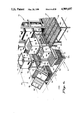
- FIG. 1 is a front perspective view of two automated work stations shown, each in company with an appropriate vertical conveyor and related horizontal conveyors.
- FIG. 2 is a plan view of the work stations showing the relationship of the various functions.
- FIG. 3 is a front perspective view of a portion of the work station with other portions removed for easy visibility.
- FIG. 4 is a front perspective view of the work station and with all parts in place and in one attitude of operation.
- FIG. 5 is a view similar to FIG. 4, but with parts in another attitude of operation.
- FIG. 6 is a view similar to FIG. 4, but showing the parts in still another attitude of operation.
- FIG. 7 is a plan view of the work table shown in association with a fragment of a supply conveyor.
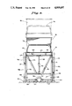
- FIG. 8 is a front elevational view of the work table on the line 8--8 of FIG. 7.
- FIG. 9 is a side elevational view of the work table on the line 9--9 of FIG. 7.
- FIG. 10 is a fragmentary vertical side sectional view of a mechanized leg of the work table.
- FIG. 11 is a fragmentary vertical front sectional view of a mechanized leg.
- FIG. 12 is a cross-sectional view on the line 12--12 of FIG. 11.
- FIG. 13 is a cross-sectional view on the line 13--13 of FIG. 11.
- FIGS. 1, 2, 4 and 5 two identical work stations 10 and 11 with identical vertical conveyors or random vertical queues 12 and 13 serving them are shown, see FIGS. 1, 2, 4 and 5.
- a horizontal outflow conveyor 17 has a loading end 19 adjacent the work stations and a more remotely disposed end 19'.
- Material transport units 18, multiple in number, are shown in various positions on the conveyors and at the work stations. Additional particulars with respect to a work station 11 taken as an example are shown in FIGS. 7 through 13, inclusive.
- a work table Immediately adjacent a work area 20 there is a work table, indicated by the reference character 21, consisting in the main of a shelf structure 32 and associated platform 22 carried by a table mechanism 23, mounted on a supporting base 24. Between the work table 21 and its vertical conveyor 12 is a transition table 25.
- the transition table 25 is shown advantageously in FIG. 3, wherein a showing of the work table has been dispensed with in order to more readily portray the structure of the transition table.
- An upper platform at the location 26 and a lower platform at the location 27 supported, for example, by corner posts 28 comprise broadly the transition table.
- the upper platform 26 consists generally of a pair of chain drive transfer belts 29 which are aligned in receiving relationship from the adjacent edge of stations on the vertical conveyor 13 which carry the material transport units 18.
- the upper platform 26 is located at an elevation which is coincident with the elevation of that station of the vertical conveyor 13 which is the station immediately above the lowermost station on the side of the vertical conveyor which faces the work table 21. With this being the position of the upper platform 26, material transport units 18 can readily be slid from their station on the vertical conveyor to a position supported by the upper platform 26 and its pair of chain drive transfer belts.
- the lower platform 27 is of more composite construction in that it consists of a pair of chain drive transfer belts 31 intermeshed between pairs of horizontally spaced parallel traction rollers 30.
- the chain drive transfer belts may be defined as having a pop-up capability in that they can be lifted so that the upper faces are in fact in a position acting as a temporary platform to support the material transport units when they reach the lower platform 27.
- the transfer belts are actually capable of carrying the material transport unit in a direction at right angles to the direction in which it is moved by the traction rollers 30.
- the chain drive transfer belts are so constructed that they can be lowered until the upper level of the belts is below the topmost surface of the rollers.
- the units resting on rollers 30 acting as a temporary platform are then free to be moved by the rollers instead of the transfer belts, obviously in a direction at right angles to what movement is experienced when the units are carried by the transfer belts.
- the mechanism 23 of the work table 21 is of a character enabling the platform 22 to be moved to a position at the same level as the upper platform 26 of the transition table of the lower platform 27, in addition to other positioning attributes of the work table.
- the platform 22 is supported by a pair of racks in the form of articulated leg assemblies 35 and 36.
- Structure comprising the articulated leg assemblies consists in part of a hollow column 37 for the leg assembly 35 and a similar hollow column 38 for the leg assembly 36.
- the platform 22 is connected to the upper beam 40 and columns 37 and 38 by means of a hinge 45. This enables the platform 22 to be tilted between a horizontal position, as shown in FIGS. 9 and 10, and an extreme tilted position, as shown by the broken lines in FIG. 9. Tilting is accomplished by use of a hydraulic ram 46, the cylindrical portion of which is pivotally attached by a bracket 47 to the lower beam 39.
- a piston 48 of the hydraulic ram is pivotally attached by means of a bracket 49 to the platform 22.
- a driven shaft 58 on the opposite side is in communication with a chain driven mechanism in the other column 38.
- the driven shaft 57 journalled as shown by a bushing 59 at the bottom of the column 37, has mounted thereon a gear 60 keyed to the shaft.
- An endless chain 61 driven by the gear 60 extends upwardly within a chamber 62 in the column 38 to engagement with an idler gear 63 on a stub shaft 64 secured within the chamber 62.
- traveling shaft 65 extending transversely from a bushing 66 through a panel 66' and into the chamber 62 where it is journaled in a traveling bracket 67.
- the traveling bracket 67 is in turn attached to the adjacent link of the endless chain 61 so that, as viewed in FIG. 10, the traveling bracket is attached to the right-hand loop of the chain at the uppermost of its operative positions.
- roller 68 mounted at the adjacent end of the traveling shaft 65, the roller being adapted to rotate on one side of the chamber 62 as the traveling bracket 67 and the roller moves up and down by action of the driven shaft 57 and its gear 60.
- the chain drive mechanism within the column 38 is the same in all operative respects as within the column 37 except for left and right-hand rotation.
- the roller 68 acts to stabilize the lower ends of the side elements 41 and 42. Additional stabilization is provided by a roller 69 mounted on a shaft 70, in turn contained with a bushing 71 at the top of the column 37, as viewed in FIG. 11.
- roller 69 rolls within a channel 72, for example, in the side element 41.
- a similar roller 69 rolls or travels in a comparable channel 72 in the side element 42. It follows, therefore, that by simultaneous operation of the two driven shafts 57 and 58 and corresponding gear 60, the endless chain 61 will carry the traveling bracket 67 on both sides upwardly or downwardly.
- the traveling brackets 67 As viewed in FIGS. 10 and 11, the traveling brackets 67, being in uppermost position, will have moved the platform 22 of the work table 21 to its uppermost level. Clockwise rotation of the gear 60 thereafter will drive the endless chain 61 in a direction so that the traveling brackets 67 will be carried downwardly to the lowermost position, namely, the position shown in FIG. 9. In that position the platform 22 will be at its lowermost level.
- the electric motor 55 By appropriate manipulation of the electric motor 55, the location of the platform 22 can be shifted to any level intermediate uppermost and lowermost positions as heretofore described.
- the work table 21 and its platform 22 heretofore identified is provided with a set of traction rollers 75 which accept the material transport unit 18 and are capable when the platform is horizontally disposed of drawing it into position on the platform until it engages the stop bar 76.
- the traction rollers driven by an endless chain are also capable of returning the material transport unit 18 to the transition table 25 when necessary.
- a pair of chain drive belts 78 which have the pop-up capability previously made reference to so that they can be raised to a level higher than the top level of the traction rollers 75, there to engage the bottom of the material transport unit 18.
- the unit 18 After the unit 18 has served the purpose for which it has been called to the tilt position of FIG. 9, it may be returned to the transition table 25. This is accomplished by lowering the platform 22 to the level of the lower platform 27. At the lower level the set of traction rollers 75 by reverse operation assists in returning the unit 18 from the work table 21 to the lower platform 27 of the transition table. Once on the lower platform 27, the unit 18 can be returned to the vertical conveyor 13 by operation of the chain drive transfer belts 31. In the alternative, the unit 18 can be diverted from the transition table 25 on the rollers 30 to a receiving station 79 of the outflow conveyor 17, see FIGS. 1, 2 and 7.
- Movement onto the receiving station 86 is assisted by employment of use of the rollers 30 as traction rollers and by appropriate pop-up chain drive belts 80, FIGS. 3, 4, 5 and 6. Once in position on the outflow conveyor 17, power rollers of the conveyor are available to dispose of the unit 18.
- the work table 21 may be used to serve auxiliary conveyors 81 from a level position of the platform 22 at any horizontal location between the lowermost level of FIG. 9 and the uppermost level of FIG. 10.
- the lowermost level of the platform may be adjusted to one below the bottom level of the adjacent vertical conveyor 12 or 13 so that units 18 may be passed to a conveyor traveling underneath.
- the platform 22 may be set in a tilt position to receive units by gravity deposit rather than by traction rollers as described on a horizontal plane.
- the platform may be set to provide a rearward tilt for return of the units 18 by gravity to the transition table 25, as by changing the hinge 45 and the length of extension of the hydraulic ram 46.
- Units 18 from the lower platform 27 of the left-hand work station can readily travel, first through the lower level of the right-hand work table 27, as viewed in FIG. 6, for example, to the receiving station 79. Additionally, for all types of containers and all types of contents, an operator can readily adjust the working height of the tilted unit so as to be able to handle the contents with the greatest speed and ease, and with a relatively minimum expenditure of physical effort and consequent time-saving efficiency.
Abstract
Description
Claims (12)
Priority Applications (1)
| Application Number | Priority Date | Filing Date | Title |
|---|---|---|---|
| US07/233,996 US4909697A (en) | 1986-01-02 | 1988-08-15 | Automated work station |
Applications Claiming Priority (2)
| Application Number | Priority Date | Filing Date | Title |
|---|---|---|---|
| US81580886A | 1986-01-02 | 1986-01-02 | |
| US07/233,996 US4909697A (en) | 1986-01-02 | 1988-08-15 | Automated work station |
Related Parent Applications (1)
| Application Number | Title | Priority Date | Filing Date |
|---|---|---|---|
| US81580886A Continuation | 1985-05-13 | 1986-01-02 |
Publications (1)
| Publication Number | Publication Date |
|---|---|
| US4909697A true US4909697A (en) | 1990-03-20 |
Family
ID=26927441
Family Applications (1)
| Application Number | Title | Priority Date | Filing Date |
|---|---|---|---|
| US07/233,996 Expired - Fee Related US4909697A (en) | 1986-01-02 | 1988-08-15 | Automated work station |
Country Status (1)
| Country | Link |
|---|---|
| US (1) | US4909697A (en) |
Cited By (104)
| Publication number | Priority date | Publication date | Assignee | Title |
|---|---|---|---|---|
| WO1989007563A1 (en) | 1988-02-22 | 1989-08-24 | Computer Aided Systems, Inc. | System for delivery |
| US5135344A (en) * | 1986-12-25 | 1992-08-04 | Kabushikkaisha Itoki Kosakusho | Automatic storage/retrieval apparatus for articles |
| US5218812A (en) * | 1991-09-05 | 1993-06-15 | Bud Of California | Packing station for lettuce receiving trays |
| US5222855A (en) * | 1986-01-02 | 1993-06-29 | Computer Aided Systems, Inc. | Automated work center |
| WO1993014008A1 (en) * | 1992-01-17 | 1993-07-22 | Rowe William A Jr | Indexing, bi-directional vertical sorter with buffer conveyors |
| US5237510A (en) * | 1990-03-20 | 1993-08-17 | Fujitsu Limited | Transportation system for products operated on by manufacturing on testing units |
| US5238351A (en) * | 1985-05-13 | 1993-08-24 | Computer Aided Systems, Inc. | Organizer system and method for a rotatable storage structure |
| US5246332A (en) * | 1985-05-13 | 1993-09-21 | Computer Aided Systems, Inc. | System for delivery |
| US5273392A (en) * | 1986-01-02 | 1993-12-28 | Computer Aided Systems, Inc. | Automated work center and method |
| US5337880A (en) * | 1993-07-23 | 1994-08-16 | Automated Systems, Inc. | Article storage carousel with automatic conveyor loading and unloading |
| EP0678462A1 (en) * | 1994-04-19 | 1995-10-25 | Bellheimer Metallwerk GmbH | High-rise storage rack |
| US5472309A (en) * | 1985-05-13 | 1995-12-05 | Computer Aided Systems, Inc. | System for delivery |
| US5513936A (en) * | 1994-04-18 | 1996-05-07 | The Champion Company | Container transfer and user interface for over/under conveyors |
| US5517799A (en) * | 1994-07-25 | 1996-05-21 | Russell; Donald J. | Onion loader/unloader conveyor system |
| US5577367A (en) * | 1994-06-10 | 1996-11-26 | Johnson & Johnson Vision Products, Inc. | Apparatus and method for sterilization and secondary packaging |
| US5588790A (en) | 1993-11-01 | 1996-12-31 | Lichti Robert D | High speed storage system |
| US5672040A (en) * | 1994-03-07 | 1997-09-30 | Sony Corporation | Parts feeding apparatus and parts feeding process |
| US5715660A (en) * | 1995-12-05 | 1998-02-10 | Balentine; Paul | Automated product collection apparatus |
| US5863172A (en) * | 1997-02-07 | 1999-01-26 | Computer Aided Systems, Inc. | Staging, tracking and retrieval system with a rotatable storage structure |
| EP1010647A1 (en) * | 1998-12-18 | 2000-06-21 | Lanfranco Anzani | System for the automatic loading and/or unloading of products |
| US6094885A (en) * | 1998-07-28 | 2000-08-01 | Payless Shoesource, Inc. | Packaging station |
| EP1041017A1 (en) * | 1999-03-30 | 2000-10-04 | Siemens Aktiengesellschaft | Device for transloading and accumulating of transport goods |
| US6134862A (en) * | 1997-01-28 | 2000-10-24 | Atlas S.A. | Device for presenting and adjusting a stock box for removing or storing articles |
| US6171129B1 (en) | 1999-04-23 | 2001-01-09 | Duane A. Phillips | Locking electrical adapter |
| US6390278B1 (en) | 2000-08-29 | 2002-05-21 | Edmund W. Brown | Transfer mechanism for multiple level conveyor |
| EP1331179A1 (en) * | 2002-01-29 | 2003-07-30 | SWISSLOG ITALIA S.p.A. | System and method for commissioning goods |
| US6609607B2 (en) * | 2000-04-27 | 2003-08-26 | Rapistan Systems Advertising Corp. | Article separation conveyor |
| US20040093832A1 (en) * | 2002-11-13 | 2004-05-20 | Ringel David W. | Work cell |
| US20040172920A1 (en) * | 2003-03-03 | 2004-09-09 | Garcia Jose Luis | Produce harvesting and wrapping apparatus and method |
| US20040193311A1 (en) * | 2003-03-26 | 2004-09-30 | Walter Winkler | Automated system and method of storing and picking articles |
| EP1452462A3 (en) * | 2003-02-25 | 2004-11-03 | WITRON Logistik & Informatik GmbH | System and method for commissioning articles disposed in storage containers |
| US20040238326A1 (en) * | 2002-10-08 | 2004-12-02 | Wayne Lichti | Method and apparatus for material handling and storage |
| US20070057477A1 (en) * | 2005-09-09 | 2007-03-15 | Topper Industrial, Inc. | Tugger cart with tiltable platform |
| US20080008568A1 (en) * | 2006-06-27 | 2008-01-10 | Brad Harris | Automated Stocking And Retrieval System |
| US20090136328A1 (en) * | 2006-05-24 | 2009-05-28 | Gerhard Schafer | Rack-Integrated Packing Station and Order-Picking Method |
| US20090294253A1 (en) * | 2008-05-30 | 2009-12-03 | Howard Eisenberg | Apparatus and method for diverting in a conveying system |
| US20090314606A1 (en) * | 2007-07-04 | 2009-12-24 | Wolfgang Henze | Discharge apparatus for a production facility |
| US20100061833A1 (en) * | 2008-09-09 | 2010-03-11 | Walter Winkler | Conveyor system, storage and retrieval device and logistics system |
| US20110008137A1 (en) * | 2008-09-03 | 2011-01-13 | Dematic Gmbh | Automated three dimensional warehouse |
| US20110073534A1 (en) * | 2009-09-28 | 2011-03-31 | Niels Linge | Sorting Installation and Method for Sorting Articles |
| US20110130869A1 (en) * | 2009-11-27 | 2011-06-02 | Psb Intralogistics Gmbh | Sorting Installation and Method for Sorting |
| US20110130708A1 (en) * | 2009-05-13 | 2011-06-02 | Minnow Medical, Inc. | Directional Delivery of Energy and Bioactives |
| US20110203231A1 (en) * | 2010-02-19 | 2011-08-25 | Dematic Corp. | Goods-to-person picking station and picking method |
| WO2011120067A2 (en) | 2010-04-02 | 2011-10-06 | Tgw Mechanics Gmbh | Method for loading, loading station and loading system |
| AT509693A1 (en) * | 2010-04-02 | 2011-10-15 | Tgw Mechanics Gmbh | PROCESSES FOR PICKING, PICKING STATION AND COMMISSIONING SYSTEM |
| US20120020767A1 (en) * | 2006-05-24 | 2012-01-26 | Ssi Schäfer Peem Gmbh Lager -Und Systemtechnik | Packing Station and Order-Picking Method |
| WO2012069327A1 (en) * | 2010-11-24 | 2012-05-31 | Knapp Ag | Picking method and system |
| EP2487123A1 (en) * | 2011-02-11 | 2012-08-15 | Savoye | Order picking station including at least one stack for vertical accumulation and sequenced distribution of containers. |
| DE102011018983A1 (en) * | 2011-04-28 | 2012-10-31 | Bernhard Stock | Picking system for use with picking area for manual picking of articles from source containers in target container, has multiple tray conveyors that are provided for target container and source container |
| US20130056576A1 (en) * | 2011-02-25 | 2013-03-07 | Curt G. Joa, Inc. | Methods and apparatus for forming disposable products at high speeds with small machine footprint |
| AT511867A1 (en) * | 2011-09-05 | 2013-03-15 | Tgw Mechanics Gmbh | PICKING STATION AND METHOD OF PICKING ARTICLES OUT OF LOADING TOOLS |
| DE102013210196A1 (en) * | 2013-05-31 | 2014-12-04 | Kardex Produktion Deutschland Gmbh | Pivoting handling device for trays of a storage and / or picking system |
| US8919801B2 (en) | 2010-12-15 | 2014-12-30 | Symbotic, LLC | Suspension system for autonomous transports |
| US8965619B2 (en) | 2010-12-15 | 2015-02-24 | Symbotic, LLC | Bot having high speed stability |
| US8998554B2 (en) | 2010-12-15 | 2015-04-07 | Symbotic Llc | Multilevel vertical conveyor platform guides |
| US9051120B2 (en) | 2009-04-10 | 2015-06-09 | Symbotic Llc | Control system for storage and retrieval systems |
| US9082112B2 (en) | 2010-12-15 | 2015-07-14 | Symbotic, LLC | Autonomous transport vehicle charging system |
| CN104925437A (en) * | 2015-05-07 | 2015-09-23 | 华中科技大学 | Expansible intelligent warehousing system facing SMD |
| US9187244B2 (en) | 2010-12-15 | 2015-11-17 | Symbotic, LLC | BOT payload alignment and sensing |
| RU2574308C2 (en) * | 2011-02-11 | 2016-02-10 | Савуа | Plant with order completion station |
| US9283683B2 (en) | 2013-07-24 | 2016-03-15 | Curt G. Joa, Inc. | Ventilated vacuum commutation structures |
| US9289329B1 (en) | 2013-12-05 | 2016-03-22 | Curt G. Joa, Inc. | Method for producing pant type diapers |
| US9321591B2 (en) | 2009-04-10 | 2016-04-26 | Symbotic, LLC | Autonomous transports for storage and retrieval systems |
| US9469208B2 (en) | 2013-03-15 | 2016-10-18 | Symbotic, LLC | Rover charging system |
| US9475649B2 (en) | 2010-12-15 | 2016-10-25 | Symbolic, LLC | Pickface builder for storage and retrieval systems |
| US9481517B2 (en) | 2013-03-15 | 2016-11-01 | Symbotic, LLC | Multiposition lift |
| US9499338B2 (en) | 2010-12-15 | 2016-11-22 | Symbotic, LLC | Automated bot transfer arm drive system |
| US9561905B2 (en) | 2010-12-15 | 2017-02-07 | Symbotic, LLC | Autonomous transport vehicle |
| US9802761B2 (en) | 2013-03-15 | 2017-10-31 | Symbotic, LLC | Automated storage and retrieval system |
| NO20160972A1 (en) * | 2016-06-06 | 2017-12-07 | Autostore Tech As | Conveyor with tilt function |
| KR20180016422A (en) * | 2015-06-08 | 2018-02-14 | 오카도 이노베이션 리미티드 | Object storage, handling, and retrieval systems and methods |
| US10150626B2 (en) * | 2016-06-15 | 2018-12-11 | Intelligrated Headquarters, Llc | Goods to operator workstation |
| US10167156B2 (en) | 2015-07-24 | 2019-01-01 | Curt G. Joa, Inc. | Vacuum commutation apparatus and methods |
| US10167145B2 (en) * | 2015-12-22 | 2019-01-01 | Dematic Corp. | Pick or put station with controllable receptacle exchange |
| NO20171688A1 (en) * | 2017-10-20 | 2019-04-22 | Autostore Tech As | Bin holding device |
| NO20181581A1 (en) * | 2018-06-12 | 2019-12-13 | Autostore Tech As | An automated storage and retrieval system with an access point and a method thereof |
| NO20181005A1 (en) * | 2018-06-12 | 2019-12-13 | Autostore Tech As | An automated storage and retrieval system and a method of transporting storage containers between an automated storage and retrieval grid and a second location |
| US20200017312A1 (en) * | 2016-12-19 | 2020-01-16 | Jörn Becher | End-point device for a sorting and picking system |
| NO20181318A1 (en) * | 2018-10-12 | 2020-04-13 | Autostore Tech As | An access station for picking storage containers |
| US10696492B2 (en) * | 2018-06-14 | 2020-06-30 | Mecatherm | Noria-type device for transporting support plates for bakery products or the like |
| US10822168B2 (en) | 2010-12-15 | 2020-11-03 | Symbotic Llc | Warehousing scalable storage structure |
| US10829313B2 (en) * | 2018-08-02 | 2020-11-10 | Intelligrated Headquarters, Llc | Goods to operator workstation |
| US10894663B2 (en) | 2013-09-13 | 2021-01-19 | Symbotic Llc | Automated storage and retrieval system |
| US20210198040A1 (en) * | 2019-12-31 | 2021-07-01 | United Parcel Service Of America, Inc. | Asset Loading System |
| US11078017B2 (en) | 2010-12-15 | 2021-08-03 | Symbotic Llc | Automated bot with transfer arm |
| US11325801B2 (en) | 2015-10-13 | 2022-05-10 | Curt G. Joa, Inc. | Disposable product assembly systems and methods |
| US11352016B2 (en) | 2018-06-12 | 2022-06-07 | Autostore Technology AS | Storage system |
| CN115195912A (en) * | 2022-09-16 | 2022-10-18 | 江苏冠宇机械设备制造有限公司 | Automobile assembly transfer chain |
| US11479407B2 (en) | 2018-01-09 | 2022-10-25 | Autostore Technology AS | Displacement mechanism for a remotely operated vehicle |
| US11485375B2 (en) | 2018-06-12 | 2022-11-01 | Autostore Technology AS | Unloading arrangement and unloading station, as well as method of unloading an item from a storage container |
| US11498757B2 (en) | 2018-06-12 | 2022-11-15 | Autostore Technology AS | Storage system |
| US11505198B2 (en) | 2018-06-12 | 2022-11-22 | Autostore Technology AS | Vehicle tilting device, an access station, a delivery system and a method of accessing a storage container |
| US11572231B2 (en) | 2018-06-12 | 2023-02-07 | Autostore Technology AS | Storage system with modular container handling vehicles |
| US11582921B2 (en) * | 2018-12-27 | 2023-02-21 | Jacobus Alexander Jozef Lemmen | System for growing mushrooms |
| US11603107B2 (en) | 2018-06-12 | 2023-03-14 | Autostore Technology AS | Unloading arrangement and unloading station, as well as method of unloading an item from a storage container |
| US11628849B2 (en) | 2018-06-12 | 2023-04-18 | Autostore Technology AS | Express bin lift for automated storage system |
| US11685391B2 (en) | 2018-06-12 | 2023-06-27 | Autostore Technology AS | Automated storage and retrieval system and a method of transporting storage containers between an automated storage and retrieval grid and a second location |
| US11691635B2 (en) | 2018-06-12 | 2023-07-04 | Autostore Technology AS | Storage grid with container accessing station with locking device to lock remotely operated vehicle |
| US11697422B2 (en) | 2018-06-12 | 2023-07-11 | Autostore Technology AS | Delivery vehicle, an automated storage and retrieval system and a method of transporting storage containers between an automated storage and retrieval grid and a second location |
| US11772685B2 (en) | 2018-06-12 | 2023-10-03 | Autostore Technology AS | System for storing and transporting storage containers |
| US11820389B2 (en) | 2018-06-12 | 2023-11-21 | Autostore Technology AS | Container accessing station with lifting device |
| US11873014B2 (en) | 2018-06-12 | 2024-01-16 | Autostore Technology AS | Delivery system with an access point and a method of accessing an access point of the delivery system |
| US11891095B2 (en) | 2018-06-12 | 2024-02-06 | Autostore Technology AS | Method for handling malfunctioning vehicles on a rail system and a storage and retrieval system using such a method |
| JP7459754B2 (en) | 2020-10-14 | 2024-04-02 | 村田機械株式会社 | Picking System |
Citations (19)
| Publication number | Priority date | Publication date | Assignee | Title |
|---|---|---|---|---|
| US1525870A (en) * | 1923-10-09 | 1925-02-10 | Clarence P Lee | Automatic fruit elevator |
| DE424919C (en) * | 1926-02-05 | Siegerin Goldman Werke G M B H | Umfuehrungs-device for single chain swing elevators, bucket elevators and. like | |
| US2353638A (en) * | 1942-04-10 | 1944-07-18 | Western Electric Co | Conveyer system |
| FR1343507A (en) * | 1962-02-19 | 1963-11-22 | Duerkopp Maschb Ges M B H | Device for receiving, supplying and returning containers or supports for material to be transported to each workplace of a transport facility |
| US3133622A (en) * | 1961-07-20 | 1964-05-19 | Pfaff Ag G M | Conveyer |
| US3268055A (en) * | 1963-08-24 | 1966-08-23 | Stein Karl | Drying device for the soles of shoes |
| US3379321A (en) * | 1966-02-25 | 1968-04-23 | Fmc Corp | Carrier with an article label unit for a warehouse system |
| US3534850A (en) * | 1969-08-11 | 1970-10-20 | Mac Mfg Co Inc | Barrel transfer device |
| US3670867A (en) * | 1969-11-17 | 1972-06-20 | Fmc Corp | Conveyor system |
| US3792785A (en) * | 1973-01-26 | 1974-02-19 | Fmc Corp | Automated storage and freight terminal apparatus |
| US3792757A (en) * | 1970-06-29 | 1974-02-19 | M Musser | Basket-cart unload apparatus for supermarkets |
| US3928114A (en) * | 1974-03-26 | 1975-12-23 | Gen Concrete Of Canada Limited | Apparatus for building of structural components |
| US4013186A (en) * | 1974-12-24 | 1977-03-22 | Nrm Corporation | Tire press unloader |
| US4192496A (en) * | 1978-03-09 | 1980-03-11 | General Corrugated Machinery Co., Inc. | Apparatus for feeding case blank sheets |
| SU755693A1 (en) * | 1978-04-26 | 1980-08-15 | G Pi Rospishchepromavtomatika | Storehouse for storing piece weights |
| US4227607A (en) * | 1979-04-16 | 1980-10-14 | Malavenda Peter P | High volume method and system for dynamically storing articles for sorting and routing |
| US4239436A (en) * | 1971-02-09 | 1980-12-16 | Anton Wildenaur | Warehousing apparatus for moving goods |
| US4379671A (en) * | 1978-05-26 | 1983-04-12 | National Can Corporation | Synchronized bottle unloading system |
| US4492504A (en) * | 1981-12-07 | 1985-01-08 | Bell & Howell Company | Materials handling system |
-
1988
- 1988-08-15 US US07/233,996 patent/US4909697A/en not_active Expired - Fee Related
Patent Citations (19)
| Publication number | Priority date | Publication date | Assignee | Title |
|---|---|---|---|---|
| DE424919C (en) * | 1926-02-05 | Siegerin Goldman Werke G M B H | Umfuehrungs-device for single chain swing elevators, bucket elevators and. like | |
| US1525870A (en) * | 1923-10-09 | 1925-02-10 | Clarence P Lee | Automatic fruit elevator |
| US2353638A (en) * | 1942-04-10 | 1944-07-18 | Western Electric Co | Conveyer system |
| US3133622A (en) * | 1961-07-20 | 1964-05-19 | Pfaff Ag G M | Conveyer |
| FR1343507A (en) * | 1962-02-19 | 1963-11-22 | Duerkopp Maschb Ges M B H | Device for receiving, supplying and returning containers or supports for material to be transported to each workplace of a transport facility |
| US3268055A (en) * | 1963-08-24 | 1966-08-23 | Stein Karl | Drying device for the soles of shoes |
| US3379321A (en) * | 1966-02-25 | 1968-04-23 | Fmc Corp | Carrier with an article label unit for a warehouse system |
| US3534850A (en) * | 1969-08-11 | 1970-10-20 | Mac Mfg Co Inc | Barrel transfer device |
| US3670867A (en) * | 1969-11-17 | 1972-06-20 | Fmc Corp | Conveyor system |
| US3792757A (en) * | 1970-06-29 | 1974-02-19 | M Musser | Basket-cart unload apparatus for supermarkets |
| US4239436A (en) * | 1971-02-09 | 1980-12-16 | Anton Wildenaur | Warehousing apparatus for moving goods |
| US3792785A (en) * | 1973-01-26 | 1974-02-19 | Fmc Corp | Automated storage and freight terminal apparatus |
| US3928114A (en) * | 1974-03-26 | 1975-12-23 | Gen Concrete Of Canada Limited | Apparatus for building of structural components |
| US4013186A (en) * | 1974-12-24 | 1977-03-22 | Nrm Corporation | Tire press unloader |
| US4192496A (en) * | 1978-03-09 | 1980-03-11 | General Corrugated Machinery Co., Inc. | Apparatus for feeding case blank sheets |
| SU755693A1 (en) * | 1978-04-26 | 1980-08-15 | G Pi Rospishchepromavtomatika | Storehouse for storing piece weights |
| US4379671A (en) * | 1978-05-26 | 1983-04-12 | National Can Corporation | Synchronized bottle unloading system |
| US4227607A (en) * | 1979-04-16 | 1980-10-14 | Malavenda Peter P | High volume method and system for dynamically storing articles for sorting and routing |
| US4492504A (en) * | 1981-12-07 | 1985-01-08 | Bell & Howell Company | Materials handling system |
Cited By (198)
| Publication number | Priority date | Publication date | Assignee | Title |
|---|---|---|---|---|
| US5238351A (en) * | 1985-05-13 | 1993-08-24 | Computer Aided Systems, Inc. | Organizer system and method for a rotatable storage structure |
| US5472309A (en) * | 1985-05-13 | 1995-12-05 | Computer Aided Systems, Inc. | System for delivery |
| US5246332A (en) * | 1985-05-13 | 1993-09-21 | Computer Aided Systems, Inc. | System for delivery |
| US5273392A (en) * | 1986-01-02 | 1993-12-28 | Computer Aided Systems, Inc. | Automated work center and method |
| US5222855A (en) * | 1986-01-02 | 1993-06-29 | Computer Aided Systems, Inc. | Automated work center |
| US5593269A (en) * | 1986-01-02 | 1997-01-14 | Computer Aided Systems, Inc. | Automated work center |
| US5135344A (en) * | 1986-12-25 | 1992-08-04 | Kabushikkaisha Itoki Kosakusho | Automatic storage/retrieval apparatus for articles |
| WO1989007563A1 (en) | 1988-02-22 | 1989-08-24 | Computer Aided Systems, Inc. | System for delivery |
| US5237510A (en) * | 1990-03-20 | 1993-08-17 | Fujitsu Limited | Transportation system for products operated on by manufacturing on testing units |
| US5218812A (en) * | 1991-09-05 | 1993-06-15 | Bud Of California | Packing station for lettuce receiving trays |
| WO1993014008A1 (en) * | 1992-01-17 | 1993-07-22 | Rowe William A Jr | Indexing, bi-directional vertical sorter with buffer conveyors |
| US5337880A (en) * | 1993-07-23 | 1994-08-16 | Automated Systems, Inc. | Article storage carousel with automatic conveyor loading and unloading |
| US5588790A (en) | 1993-11-01 | 1996-12-31 | Lichti Robert D | High speed storage system |
| US5919025A (en) * | 1994-03-07 | 1999-07-06 | Sony Corporation | Parts feeding apparatus and parts feeding process |
| US5672040A (en) * | 1994-03-07 | 1997-09-30 | Sony Corporation | Parts feeding apparatus and parts feeding process |
| US5513936A (en) * | 1994-04-18 | 1996-05-07 | The Champion Company | Container transfer and user interface for over/under conveyors |
| EP0678462A1 (en) * | 1994-04-19 | 1995-10-25 | Bellheimer Metallwerk GmbH | High-rise storage rack |
| DE4416102A1 (en) * | 1994-04-19 | 1995-10-26 | Bellheimer Metallwerk Gmbh | high level rack |
| US5577367A (en) * | 1994-06-10 | 1996-11-26 | Johnson & Johnson Vision Products, Inc. | Apparatus and method for sterilization and secondary packaging |
| US5517799A (en) * | 1994-07-25 | 1996-05-21 | Russell; Donald J. | Onion loader/unloader conveyor system |
| SG79919A1 (en) * | 1995-05-01 | 2001-04-17 | Johnson & Johnson Vision Prod | Apparatus and method for sterilization and second packaging |
| US5715660A (en) * | 1995-12-05 | 1998-02-10 | Balentine; Paul | Automated product collection apparatus |
| US6134862A (en) * | 1997-01-28 | 2000-10-24 | Atlas S.A. | Device for presenting and adjusting a stock box for removing or storing articles |
| US5863172A (en) * | 1997-02-07 | 1999-01-26 | Computer Aided Systems, Inc. | Staging, tracking and retrieval system with a rotatable storage structure |
| US6094885A (en) * | 1998-07-28 | 2000-08-01 | Payless Shoesource, Inc. | Packaging station |
| EP1010647A1 (en) * | 1998-12-18 | 2000-06-21 | Lanfranco Anzani | System for the automatic loading and/or unloading of products |
| US6357985B1 (en) | 1998-12-18 | 2002-03-19 | Lanfranco Anzani | System for the automatic loading and/or unloading of products |
| EP1041017A1 (en) * | 1999-03-30 | 2000-10-04 | Siemens Aktiengesellschaft | Device for transloading and accumulating of transport goods |
| US6171129B1 (en) | 1999-04-23 | 2001-01-09 | Duane A. Phillips | Locking electrical adapter |
| US6609607B2 (en) * | 2000-04-27 | 2003-08-26 | Rapistan Systems Advertising Corp. | Article separation conveyor |
| US20060289278A1 (en) * | 2000-08-29 | 2006-12-28 | Brown Edmund W | Transfer mechanism incorporating dampening cylinder |
| US6390278B1 (en) | 2000-08-29 | 2002-05-21 | Edmund W. Brown | Transfer mechanism for multiple level conveyor |
| WO2003064292A1 (en) * | 2002-01-29 | 2003-08-07 | Swisslog Italia S.P.A | System and method for commissioning goods |
| EP1331179A1 (en) * | 2002-01-29 | 2003-07-30 | SWISSLOG ITALIA S.p.A. | System and method for commissioning goods |
| US20040238326A1 (en) * | 2002-10-08 | 2004-12-02 | Wayne Lichti | Method and apparatus for material handling and storage |
| US20040093832A1 (en) * | 2002-11-13 | 2004-05-20 | Ringel David W. | Work cell |
| US6971214B2 (en) * | 2002-11-13 | 2005-12-06 | Hollingsworth Logistics Group | Work cell |
| EP1452462A3 (en) * | 2003-02-25 | 2004-11-03 | WITRON Logistik & Informatik GmbH | System and method for commissioning articles disposed in storage containers |
| US20040172920A1 (en) * | 2003-03-03 | 2004-09-09 | Garcia Jose Luis | Produce harvesting and wrapping apparatus and method |
| US7097045B2 (en) * | 2003-03-26 | 2006-08-29 | Witron Logistik & Informatik Gmbh | Automated system and method of storing and picking articles |
| US20040193311A1 (en) * | 2003-03-26 | 2004-09-30 | Walter Winkler | Automated system and method of storing and picking articles |
| US20070057477A1 (en) * | 2005-09-09 | 2007-03-15 | Topper Industrial, Inc. | Tugger cart with tiltable platform |
| US7497448B2 (en) * | 2005-09-09 | 2009-03-03 | Brown Edmund W | Tugger cart with tiltable platform |
| US20120020767A1 (en) * | 2006-05-24 | 2012-01-26 | Ssi Schäfer Peem Gmbh Lager -Und Systemtechnik | Packing Station and Order-Picking Method |
| US20090136328A1 (en) * | 2006-05-24 | 2009-05-28 | Gerhard Schafer | Rack-Integrated Packing Station and Order-Picking Method |
| US8556567B2 (en) * | 2006-05-24 | 2013-10-15 | Ssi Schaefer Noell Gmbh Lager- Und Systemtechnik | Packing station and order-picking method |
| US8707658B2 (en) * | 2006-05-24 | 2014-04-29 | Ssi Schafer Noell Gmbh Lager- Und Systemtechnik | Rack-integrated packing station |
| US20080008568A1 (en) * | 2006-06-27 | 2008-01-10 | Brad Harris | Automated Stocking And Retrieval System |
| US20090314606A1 (en) * | 2007-07-04 | 2009-12-24 | Wolfgang Henze | Discharge apparatus for a production facility |
| US7721870B2 (en) * | 2007-07-04 | 2010-05-25 | The Goodyear Tire & Rubber Company | Discharge apparatus for a production facility |
| US20090294253A1 (en) * | 2008-05-30 | 2009-12-03 | Howard Eisenberg | Apparatus and method for diverting in a conveying system |
| US20110008137A1 (en) * | 2008-09-03 | 2011-01-13 | Dematic Gmbh | Automated three dimensional warehouse |
| US9266675B2 (en) | 2008-09-03 | 2016-02-23 | Dematic Systems Gmbh | Automated three dimensional warehouse |
| US9162817B2 (en) * | 2008-09-09 | 2015-10-20 | Walter Winkler | Conveyor system, storage and retrieval device and logistics system |
| US20100061833A1 (en) * | 2008-09-09 | 2010-03-11 | Walter Winkler | Conveyor system, storage and retrieval device and logistics system |
| US11254501B2 (en) | 2009-04-10 | 2022-02-22 | Symbotic Llc | Storage and retrieval system |
| US9321591B2 (en) | 2009-04-10 | 2016-04-26 | Symbotic, LLC | Autonomous transports for storage and retrieval systems |
| US10207870B2 (en) | 2009-04-10 | 2019-02-19 | Symbotic, LLC | Autonomous transports for storage and retrieval systems |
| US10239691B2 (en) | 2009-04-10 | 2019-03-26 | Symbotic, LLC | Storage and retrieval system |
| US11124361B2 (en) | 2009-04-10 | 2021-09-21 | Symbotic Llc | Storage and retrieval system |
| US10759600B2 (en) | 2009-04-10 | 2020-09-01 | Symbotic Llc | Autonomous transports for storage and retrieval systems |
| US11939158B2 (en) | 2009-04-10 | 2024-03-26 | Symbotic Llc | Storage and retrieval system |
| US11858740B2 (en) | 2009-04-10 | 2024-01-02 | Symbotic Llc | Storage and retrieval system |
| US9771217B2 (en) | 2009-04-10 | 2017-09-26 | Symbotic, LLC | Control system for storage and retrieval systems |
| US9051120B2 (en) | 2009-04-10 | 2015-06-09 | Symbotic Llc | Control system for storage and retrieval systems |
| US11661279B2 (en) | 2009-04-10 | 2023-05-30 | Symbotic Llc | Autonomous transports for storage and retrieval systems |
| US20110130708A1 (en) * | 2009-05-13 | 2011-06-02 | Minnow Medical, Inc. | Directional Delivery of Energy and Bioactives |
| US20110073534A1 (en) * | 2009-09-28 | 2011-03-31 | Niels Linge | Sorting Installation and Method for Sorting Articles |
| US20110130869A1 (en) * | 2009-11-27 | 2011-06-02 | Psb Intralogistics Gmbh | Sorting Installation and Method for Sorting |
| US8713899B2 (en) | 2010-02-19 | 2014-05-06 | Dematic Corp. | Goods-to-person picking station and picking method |
| US20110203231A1 (en) * | 2010-02-19 | 2011-08-25 | Dematic Corp. | Goods-to-person picking station and picking method |
| AT509693A1 (en) * | 2010-04-02 | 2011-10-15 | Tgw Mechanics Gmbh | PROCESSES FOR PICKING, PICKING STATION AND COMMISSIONING SYSTEM |
| AT14005U1 (en) * | 2010-04-02 | 2015-02-15 | Tgw Mechanics Gmbh | PROCESSES FOR PICKING, PICKING STATION AND COMMISSIONING SYSTEM |
| WO2011120067A2 (en) | 2010-04-02 | 2011-10-06 | Tgw Mechanics Gmbh | Method for loading, loading station and loading system |
| AT509693B1 (en) * | 2010-04-02 | 2019-04-15 | Tgw Mechanics Gmbh | PROCESSES FOR PICKING, PICKING STATION AND COMMISSIONING SYSTEM |
| WO2012069327A1 (en) * | 2010-11-24 | 2012-05-31 | Knapp Ag | Picking method and system |
| US8919801B2 (en) | 2010-12-15 | 2014-12-30 | Symbotic, LLC | Suspension system for autonomous transports |
| US9499338B2 (en) | 2010-12-15 | 2016-11-22 | Symbotic, LLC | Automated bot transfer arm drive system |
| US20150239665A1 (en) * | 2010-12-15 | 2015-08-27 | Symbotic, LLC | Multilevel vertical conveyor platform guides |
| US11273981B2 (en) | 2010-12-15 | 2022-03-15 | Symbolic Llc | Automated bot transfer arm drive system |
| US9156394B2 (en) | 2010-12-15 | 2015-10-13 | Symbotic, LLC | Suspension system for autonomous transports |
| US11286118B2 (en) | 2010-12-15 | 2022-03-29 | Symbotic Llc | Pickface builder for storage and retrieval systems |
| US9187244B2 (en) | 2010-12-15 | 2015-11-17 | Symbotic, LLC | BOT payload alignment and sensing |
| US10207595B2 (en) | 2010-12-15 | 2019-02-19 | Symbotic, LLC | Autonomous transport vehicle charging system |
| US8998554B2 (en) | 2010-12-15 | 2015-04-07 | Symbotic Llc | Multilevel vertical conveyor platform guides |
| US9981808B2 (en) | 2010-12-15 | 2018-05-29 | Symbotic, LLC | Pickface builder for storage and retrieval systems |
| US11565602B2 (en) | 2010-12-15 | 2023-01-31 | Symbolic Llc | Autonomous transport vehicle charging system |
| US8965619B2 (en) | 2010-12-15 | 2015-02-24 | Symbotic, LLC | Bot having high speed stability |
| US9327903B2 (en) | 2010-12-15 | 2016-05-03 | Symbotic, LLC | Suspension system for autonomous transports |
| US9371183B2 (en) * | 2010-12-15 | 2016-06-21 | Symbotic, LLC | Multilevel vertical conveyor platform guides |
| US9423796B2 (en) | 2010-12-15 | 2016-08-23 | Symbotic Llc | Bot having high speed stability |
| US11078017B2 (en) | 2010-12-15 | 2021-08-03 | Symbotic Llc | Automated bot with transfer arm |
| US9475649B2 (en) | 2010-12-15 | 2016-10-25 | Symbolic, LLC | Pickface builder for storage and retrieval systems |
| US10981463B2 (en) | 2010-12-15 | 2021-04-20 | Symbolic Llc | Autonomous transport vehicle charging system |
| US9499062B2 (en) | 2010-12-15 | 2016-11-22 | Symbotic Llc | Autonomous transport vehicle charging system |
| US9082112B2 (en) | 2010-12-15 | 2015-07-14 | Symbotic, LLC | Autonomous transport vehicle charging system |
| US9550225B2 (en) | 2010-12-15 | 2017-01-24 | Symbotic Llc | Bot having high speed stability |
| US9561905B2 (en) | 2010-12-15 | 2017-02-07 | Symbotic, LLC | Autonomous transport vehicle |
| US11724890B2 (en) | 2010-12-15 | 2023-08-15 | Symbotic Llc | Pickface builder for storage and retrieval systems |
| US10875722B2 (en) | 2010-12-15 | 2020-12-29 | Symbotic Llc | Pickface builder for storage and retrieval systems |
| US9676551B2 (en) | 2010-12-15 | 2017-06-13 | Symbotic, LLC | Bot payload alignment and sensing |
| US9758049B2 (en) | 2010-12-15 | 2017-09-12 | Symbotic, LLC | Autonomous transport vehicle charging system |
| US11807127B2 (en) | 2010-12-15 | 2023-11-07 | Symbotic Llc | Autonomous transport vehicle charging system |
| US10822168B2 (en) | 2010-12-15 | 2020-11-03 | Symbotic Llc | Warehousing scalable storage structure |
| US10280000B2 (en) | 2010-12-15 | 2019-05-07 | Symbotic, LLC | Suspension system for autonomous transports |
| US10683169B2 (en) | 2010-12-15 | 2020-06-16 | Symbotic, LLC | Automated bot transfer arm drive system |
| US9862543B2 (en) | 2010-12-15 | 2018-01-09 | Symbiotic, LLC | Bot payload alignment and sensing |
| US10449872B2 (en) | 2010-12-15 | 2019-10-22 | Symbotic, LLC | Autonomous transport vehicle charging system |
| FR2971493A1 (en) * | 2011-02-11 | 2012-08-17 | Savoye | ORDER PREPARATION STATION COMPRISING AT LEAST ONE CHIMNEY OF VERTICAL ACCUMULATION AND SEQUENTIAL DISTRIBUTION OF CONTAINERS |
| US8996157B2 (en) | 2011-02-11 | 2015-03-31 | Savoye | Station for preparing orders comprising at least one shaft for vertically accumulating and sequentially dispensing containers |
| WO2012107534A1 (en) * | 2011-02-11 | 2012-08-16 | Savoye | Station for preparing orders, comprising at least one shaft for vertically accumulating and sequentially dispensing containers |
| EP2487123A1 (en) * | 2011-02-11 | 2012-08-15 | Savoye | Order picking station including at least one stack for vertical accumulation and sequenced distribution of containers. |
| RU2574308C2 (en) * | 2011-02-11 | 2016-02-10 | Савуа | Plant with order completion station |
| US9566193B2 (en) * | 2011-02-25 | 2017-02-14 | Curt G. Joa, Inc. | Methods and apparatus for forming disposable products at high speeds with small machine footprint |
| US9907706B2 (en) | 2011-02-25 | 2018-03-06 | Curt G. Joa, Inc. | Methods and apparatus for forming disposable products at high speeds with small machine footprint |
| US20130056576A1 (en) * | 2011-02-25 | 2013-03-07 | Curt G. Joa, Inc. | Methods and apparatus for forming disposable products at high speeds with small machine footprint |
| DE102011018983A1 (en) * | 2011-04-28 | 2012-10-31 | Bernhard Stock | Picking system for use with picking area for manual picking of articles from source containers in target container, has multiple tray conveyors that are provided for target container and source container |
| DE102011018983B4 (en) * | 2011-04-28 | 2015-03-05 | Bernhard Stock | order picking |
| US9026243B2 (en) | 2011-09-05 | 2015-05-05 | Tgw Mechanics Gmbh | Order-picking station, and method for the order-picking of articles from loading aids |
| AT511867A1 (en) * | 2011-09-05 | 2013-03-15 | Tgw Mechanics Gmbh | PICKING STATION AND METHOD OF PICKING ARTICLES OUT OF LOADING TOOLS |
| US9802761B2 (en) | 2013-03-15 | 2017-10-31 | Symbotic, LLC | Automated storage and retrieval system |
| US9481517B2 (en) | 2013-03-15 | 2016-11-01 | Symbotic, LLC | Multiposition lift |
| US10035650B2 (en) | 2013-03-15 | 2018-07-31 | Symbotic Llc | Multiposition lift |
| US10683170B2 (en) | 2013-03-15 | 2020-06-16 | Symbotic, LLC | Automated storage and retrieval system |
| US9469208B2 (en) | 2013-03-15 | 2016-10-18 | Symbotic, LLC | Rover charging system |
| US11858742B2 (en) | 2013-03-15 | 2024-01-02 | Symbotic Llc | Multiposition lift |
| US11939161B2 (en) | 2013-03-15 | 2024-03-26 | Symbotic Llc | Automated storage and retrieval system |
| US10730699B2 (en) | 2013-03-15 | 2020-08-04 | Symbotic Llc | Multiposition lift |
| US11414271B2 (en) | 2013-03-15 | 2022-08-16 | Symbotic Llc | Automated storage and retrieval system |
| US9988213B2 (en) | 2013-03-15 | 2018-06-05 | Symbotic, LLC | Automated storage and retrieval system |
| US10457484B2 (en) | 2013-03-15 | 2019-10-29 | Symbotic, LLC | Automated storage and retrieval system |
| US11273983B2 (en) | 2013-03-15 | 2022-03-15 | Symbotic Llc | Multiposition lift |
| US11565598B2 (en) | 2013-03-15 | 2023-01-31 | Symbotic Llc | Rover charging system with one or more charging stations configured to control an output of the charging station independent of a charging station status |
| WO2014191577A1 (en) * | 2013-05-31 | 2014-12-04 | Kardex Produktion Deutschland Gmbh | Pivotal handling device for shelves of a storage and/or order-picking system |
| DE102013210196A1 (en) * | 2013-05-31 | 2014-12-04 | Kardex Produktion Deutschland Gmbh | Pivoting handling device for trays of a storage and / or picking system |
| EP3003918B1 (en) | 2013-05-31 | 2017-12-20 | Kardex Produktion Deutschland GmbH | Storage and/or order-picking system with trays pivotal handling devices |
| US9283683B2 (en) | 2013-07-24 | 2016-03-15 | Curt G. Joa, Inc. | Ventilated vacuum commutation structures |
| US10894663B2 (en) | 2013-09-13 | 2021-01-19 | Symbotic Llc | Automated storage and retrieval system |
| US11708218B2 (en) | 2013-09-13 | 2023-07-25 | Symbolic Llc | Automated storage and retrieval system |
| US9289329B1 (en) | 2013-12-05 | 2016-03-22 | Curt G. Joa, Inc. | Method for producing pant type diapers |
| CN104925437B (en) * | 2015-05-07 | 2017-04-26 | 华中科技大学 | Expansible intelligent warehousing system facing SMD |
| CN104925437A (en) * | 2015-05-07 | 2015-09-23 | 华中科技大学 | Expansible intelligent warehousing system facing SMD |
| JP2021138548A (en) * | 2015-06-08 | 2021-09-16 | オカド・イノベーション・リミテッド | System and method of storing, handling, and recovering article |
| JP7242184B2 (en) | 2015-06-08 | 2023-03-20 | オカド・イノベーション・リミテッド | Goods storage, handling and recovery systems and methods |
| US11807453B2 (en) | 2015-06-08 | 2023-11-07 | Ocado Innovation Limited | Object storage, handling, and retrieving system and method |
| JP2018520965A (en) * | 2015-06-08 | 2018-08-02 | オカド・イノベーション・リミテッド | Article storage, handling and retrieval system and method |
| KR20180016422A (en) * | 2015-06-08 | 2018-02-14 | 오카도 이노베이션 리미티드 | Object storage, handling, and retrieval systems and methods |
| US10167156B2 (en) | 2015-07-24 | 2019-01-01 | Curt G. Joa, Inc. | Vacuum commutation apparatus and methods |
| US10494216B2 (en) | 2015-07-24 | 2019-12-03 | Curt G. Joa, Inc. | Vacuum communication apparatus and methods |
| US10633207B2 (en) | 2015-07-24 | 2020-04-28 | Curt G. Joa, Inc. | Vacuum commutation apparatus and methods |
| US11325801B2 (en) | 2015-10-13 | 2022-05-10 | Curt G. Joa, Inc. | Disposable product assembly systems and methods |
| US10167145B2 (en) * | 2015-12-22 | 2019-01-01 | Dematic Corp. | Pick or put station with controllable receptacle exchange |
| NO20160972A1 (en) * | 2016-06-06 | 2017-12-07 | Autostore Tech As | Conveyor with tilt function |
| NO344609B1 (en) * | 2016-06-06 | 2020-02-10 | Autostore Tech As | Conveyor with tilt function |
| US10913607B2 (en) | 2016-06-06 | 2021-02-09 | Autostore Technology AS | Storage system |
| US10150626B2 (en) * | 2016-06-15 | 2018-12-11 | Intelligrated Headquarters, Llc | Goods to operator workstation |
| US20200017312A1 (en) * | 2016-12-19 | 2020-01-16 | Jörn Becher | End-point device for a sorting and picking system |
| US11001454B2 (en) * | 2016-12-19 | 2021-05-11 | Hansueli Christen | End-point device for a sorting and picking system |
| NO20171688A1 (en) * | 2017-10-20 | 2019-04-22 | Autostore Tech As | Bin holding device |
| NO344465B1 (en) * | 2017-10-20 | 2019-12-23 | Autostore Tech As | Bin holding Device and method of arranging a top edge of a storage bin at a predetermined level in the bin holding device |
| US11801999B2 (en) | 2017-10-20 | 2023-10-31 | Autostore Technology AS | Bin holding device |
| US11235927B2 (en) | 2017-10-20 | 2022-02-01 | Autostore Technology AS | Bin holding device |
| US11548731B2 (en) | 2018-01-09 | 2023-01-10 | Autostore Technology AS | Displacement mechanism for a remotely operated vehicle |
| US11479407B2 (en) | 2018-01-09 | 2022-10-25 | Autostore Technology AS | Displacement mechanism for a remotely operated vehicle |
| US11485375B2 (en) | 2018-06-12 | 2022-11-01 | Autostore Technology AS | Unloading arrangement and unloading station, as well as method of unloading an item from a storage container |
| US11772685B2 (en) | 2018-06-12 | 2023-10-03 | Autostore Technology AS | System for storing and transporting storage containers |
| US11498757B2 (en) | 2018-06-12 | 2022-11-15 | Autostore Technology AS | Storage system |
| US11912314B2 (en) | 2018-06-12 | 2024-02-27 | Autostore Technology AS | Express bin lift for automated storage system |
| US11891095B2 (en) | 2018-06-12 | 2024-02-06 | Autostore Technology AS | Method for handling malfunctioning vehicles on a rail system and a storage and retrieval system using such a method |
| US11572231B2 (en) | 2018-06-12 | 2023-02-07 | Autostore Technology AS | Storage system with modular container handling vehicles |
| US11873014B2 (en) | 2018-06-12 | 2024-01-16 | Autostore Technology AS | Delivery system with an access point and a method of accessing an access point of the delivery system |
| US11603107B2 (en) | 2018-06-12 | 2023-03-14 | Autostore Technology AS | Unloading arrangement and unloading station, as well as method of unloading an item from a storage container |
| NO344742B1 (en) * | 2018-06-12 | 2020-03-30 | Autostore Tech As | A delivery system with an access point and a method of accessing an access point of the delivery system |
| US11628849B2 (en) | 2018-06-12 | 2023-04-18 | Autostore Technology AS | Express bin lift for automated storage system |
| US11352016B2 (en) | 2018-06-12 | 2022-06-07 | Autostore Technology AS | Storage system |
| NO344662B1 (en) * | 2018-06-12 | 2020-03-02 | Autostore Tech As | An automated storage and retrieval system and a method of transporting storage containers between an automated storage and retrieval grid and a second location |
| US11685391B2 (en) | 2018-06-12 | 2023-06-27 | Autostore Technology AS | Automated storage and retrieval system and a method of transporting storage containers between an automated storage and retrieval grid and a second location |
| US11691635B2 (en) | 2018-06-12 | 2023-07-04 | Autostore Technology AS | Storage grid with container accessing station with locking device to lock remotely operated vehicle |
| US11697422B2 (en) | 2018-06-12 | 2023-07-11 | Autostore Technology AS | Delivery vehicle, an automated storage and retrieval system and a method of transporting storage containers between an automated storage and retrieval grid and a second location |
| NO20181581A1 (en) * | 2018-06-12 | 2019-12-13 | Autostore Tech As | An automated storage and retrieval system with an access point and a method thereof |
| US11834268B2 (en) | 2018-06-12 | 2023-12-05 | Autostore Technology AS | Storage system with modular container handling vehicles |
| US11505198B2 (en) | 2018-06-12 | 2022-11-22 | Autostore Technology AS | Vehicle tilting device, an access station, a delivery system and a method of accessing a storage container |
| US11801874B2 (en) | 2018-06-12 | 2023-10-31 | Autostore Technology AS | Vehicle tilting device, an access station, a delivery system and a method of accessing a storage, etc |
| US11820389B2 (en) | 2018-06-12 | 2023-11-21 | Autostore Technology AS | Container accessing station with lifting device |
| US11814058B2 (en) | 2018-06-12 | 2023-11-14 | Autostore Technology AS | Storage system |
| NO20181005A1 (en) * | 2018-06-12 | 2019-12-13 | Autostore Tech As | An automated storage and retrieval system and a method of transporting storage containers between an automated storage and retrieval grid and a second location |
| US10696492B2 (en) * | 2018-06-14 | 2020-06-30 | Mecatherm | Noria-type device for transporting support plates for bakery products or the like |
| US11472634B2 (en) | 2018-08-02 | 2022-10-18 | Intelligrated Headquarters, Llc | Goods to operator workstation |
| US10829313B2 (en) * | 2018-08-02 | 2020-11-10 | Intelligrated Headquarters, Llc | Goods to operator workstation |
| NO344944B1 (en) * | 2018-10-12 | 2020-07-27 | Autostore Tech As | An access station for picking storage containers |
| NO20181318A1 (en) * | 2018-10-12 | 2020-04-13 | Autostore Tech As | An access station for picking storage containers |
| US20230148493A1 (en) * | 2018-12-27 | 2023-05-18 | Jacobus Alexander Jozef Lemmen | System for growing mushrooms |
| US11582921B2 (en) * | 2018-12-27 | 2023-02-21 | Jacobus Alexander Jozef Lemmen | System for growing mushrooms |
| US11492202B2 (en) * | 2019-12-31 | 2022-11-08 | United Parcel Service Of America, Inc. | Asset loading system |
| US20210198040A1 (en) * | 2019-12-31 | 2021-07-01 | United Parcel Service Of America, Inc. | Asset Loading System |
| JP7459754B2 (en) | 2020-10-14 | 2024-04-02 | 村田機械株式会社 | Picking System |
| US11952214B2 (en) | 2022-03-14 | 2024-04-09 | Symbotic Llc | Automated bot transfer arm drive system |
| CN115195912A (en) * | 2022-09-16 | 2022-10-18 | 江苏冠宇机械设备制造有限公司 | Automobile assembly transfer chain |
Similar Documents
| Publication | Publication Date | Title |
|---|---|---|
| US4909697A (en) | Automated work station | |
| AU603046B2 (en) | Mechanised storage system | |
| US5364220A (en) | Shelf servicing apparatus | |
| US20140249666A1 (en) | Order-picking station, and method for the order-picking of articles from loading aids | |
| US3554391A (en) | Elevators and rotatory storage rack | |
| US3547282A (en) | Apparatus for transient handling and storing of articles | |
| US3526327A (en) | Storage and order picking system | |
| JPH03238225A (en) | Space automatic classifying device | |
| JPS6229321B2 (en) | ||
| US3528566A (en) | Warehouse article transport vehicle with horizontal and inclined conveyors | |
| US5249915A (en) | Dual independent hoist breakdown station | |
| CN210392409U (en) | Intelligent stacking stereoscopic warehouse | |
| US5791865A (en) | Bag palletizer | |
| JP2929426B2 (en) | Article storage facility | |
| JPH06219511A (en) | Automatic warehouse for picking | |
| US5807055A (en) | Apparatus for loading and/or unloading a container with stacks of packages, such as for instance egg trays | |
| JPS6250362B2 (en) | ||
| JPS6014724B2 (en) | How to store loads of different sizes on the same shelf | |
| EP0849193A1 (en) | Wheel-mounted device for supporting product containers for preordered withdrawal | |
| JPS61257806A (en) | Automatic storehouse | |
| JPH0262304A (en) | Picker | |
| US3458061A (en) | Delivery bin storage system | |
| US5046597A (en) | Modular tray accumulator system | |
| EP0193955A1 (en) | Machine for transferring bins and the like | |
| JPH07137806A (en) | Warehousing-delivery conveyor device |
Legal Events
| Date | Code | Title | Description |
|---|---|---|---|
| CC | Certificate of correction | ||
| FEPP | Fee payment procedure |
Free format text: PAYOR NUMBER ASSIGNED (ORIGINAL EVENT CODE: ASPN); ENTITY STATUS OF PATENT OWNER: SMALL ENTITY |
|
| FPAY | Fee payment |
Year of fee payment: 4 |
|
| FEPP | Fee payment procedure |
Free format text: PAT HOLDER CLAIMS SMALL ENTITY STATUS - SMALL BUSINESS (ORIGINAL EVENT CODE: SM02); ENTITY STATUS OF PATENT OWNER: SMALL ENTITY Free format text: PAYOR NUMBER ASSIGNED (ORIGINAL EVENT CODE: ASPN); ENTITY STATUS OF PATENT OWNER: SMALL ENTITY Free format text: PAYER NUMBER DE-ASSIGNED (ORIGINAL EVENT CODE: RMPN); ENTITY STATUS OF PATENT OWNER: SMALL ENTITY |
|
| FPAY | Fee payment |
Year of fee payment: 8 |
|
| SULP | Surcharge for late payment | ||
| REMI | Maintenance fee reminder mailed | ||
| REMI | Maintenance fee reminder mailed | ||
| LAPS | Lapse for failure to pay maintenance fees | ||
| STCH | Information on status: patent discontinuation |
Free format text: PATENT EXPIRED DUE TO NONPAYMENT OF MAINTENANCE FEES UNDER 37 CFR 1.362 |
|
| FP | Lapsed due to failure to pay maintenance fee |
Effective date: 20020320 |