US4907983A - Electrical connector - Google Patents
Electrical connector Download PDFInfo
- Publication number
- US4907983A US4907983A US07/183,974 US18397488A US4907983A US 4907983 A US4907983 A US 4907983A US 18397488 A US18397488 A US 18397488A US 4907983 A US4907983 A US 4907983A
- Authority
- US
- United States
- Prior art keywords
- electrical connector
- sleeve
- connector
- set forth
- frusto
- Prior art date
- Legal status (The legal status is an assumption and is not a legal conclusion. Google has not performed a legal analysis and makes no representation as to the accuracy of the status listed.)
- Expired - Fee Related
Links
Images


Classifications
-
- H—ELECTRICITY
- H01—ELECTRIC ELEMENTS
- H01R—ELECTRICALLY-CONDUCTIVE CONNECTIONS; STRUCTURAL ASSOCIATIONS OF A PLURALITY OF MUTUALLY-INSULATED ELECTRICAL CONNECTING ELEMENTS; COUPLING DEVICES; CURRENT COLLECTORS
- H01R13/00—Details of coupling devices of the kinds covered by groups H01R12/70 or H01R24/00 - H01R33/00
- H01R13/40—Securing contact members in or to a base or case; Insulating of contact members
- H01R13/405—Securing in non-demountable manner, e.g. moulding, riveting
-
- H—ELECTRICITY
- H01—ELECTRIC ELEMENTS
- H01R—ELECTRICALLY-CONDUCTIVE CONNECTIONS; STRUCTURAL ASSOCIATIONS OF A PLURALITY OF MUTUALLY-INSULATED ELECTRICAL CONNECTING ELEMENTS; COUPLING DEVICES; CURRENT COLLECTORS
- H01R24/00—Two-part coupling devices, or either of their cooperating parts, characterised by their overall structure
- H01R24/38—Two-part coupling devices, or either of their cooperating parts, characterised by their overall structure having concentrically or coaxially arranged contacts
- H01R24/40—Two-part coupling devices, or either of their cooperating parts, characterised by their overall structure having concentrically or coaxially arranged contacts specially adapted for high frequency
- H01R24/56—Two-part coupling devices, or either of their cooperating parts, characterised by their overall structure having concentrically or coaxially arranged contacts specially adapted for high frequency specially adapted to a specific shape of cables, e.g. corrugated cables, twisted pair cables, cables with two screens or hollow cables
- H01R24/564—Corrugated cables
-
- H—ELECTRICITY
- H01—ELECTRIC ELEMENTS
- H01R—ELECTRICALLY-CONDUCTIVE CONNECTIONS; STRUCTURAL ASSOCIATIONS OF A PLURALITY OF MUTUALLY-INSULATED ELECTRICAL CONNECTING ELEMENTS; COUPLING DEVICES; CURRENT COLLECTORS
- H01R4/00—Electrically-conductive connections between two or more conductive members in direct contact, i.e. touching one another; Means for effecting or maintaining such contact; Electrically-conductive connections having two or more spaced connecting locations for conductors and using contact members penetrating insulation
- H01R4/28—Clamped connections, spring connections
- H01R4/50—Clamped connections, spring connections utilising a cam, wedge, cone or ball also combined with a screw
- H01R4/5083—Clamped connections, spring connections utilising a cam, wedge, cone or ball also combined with a screw using a wedge
-
- H—ELECTRICITY
- H01—ELECTRIC ELEMENTS
- H01R—ELECTRICALLY-CONDUCTIVE CONNECTIONS; STRUCTURAL ASSOCIATIONS OF A PLURALITY OF MUTUALLY-INSULATED ELECTRICAL CONNECTING ELEMENTS; COUPLING DEVICES; CURRENT COLLECTORS
- H01R9/00—Structural associations of a plurality of mutually-insulated electrical connecting elements, e.g. terminal strips or terminal blocks; Terminals or binding posts mounted upon a base or in a case; Bases therefor
- H01R9/03—Connectors arranged to contact a plurality of the conductors of a multiconductor cable, e.g. tapping connections
- H01R9/05—Connectors arranged to contact a plurality of the conductors of a multiconductor cable, e.g. tapping connections for coaxial cables
- H01R9/0521—Connection to outer conductor by action of a nut
-
- H—ELECTRICITY
- H01—ELECTRIC ELEMENTS
- H01R—ELECTRICALLY-CONDUCTIVE CONNECTIONS; STRUCTURAL ASSOCIATIONS OF A PLURALITY OF MUTUALLY-INSULATED ELECTRICAL CONNECTING ELEMENTS; COUPLING DEVICES; CURRENT COLLECTORS
- H01R2103/00—Two poles
-
- H—ELECTRICITY
- H01—ELECTRIC ELEMENTS
- H01R—ELECTRICALLY-CONDUCTIVE CONNECTIONS; STRUCTURAL ASSOCIATIONS OF A PLURALITY OF MUTUALLY-INSULATED ELECTRICAL CONNECTING ELEMENTS; COUPLING DEVICES; CURRENT COLLECTORS
- H01R24/00—Two-part coupling devices, or either of their cooperating parts, characterised by their overall structure
- H01R24/38—Two-part coupling devices, or either of their cooperating parts, characterised by their overall structure having concentrically or coaxially arranged contacts
- H01R24/40—Two-part coupling devices, or either of their cooperating parts, characterised by their overall structure having concentrically or coaxially arranged contacts specially adapted for high frequency
Definitions
- the present invention relates in general to an electrical connector which may be of the jack-to-jack or barrel connector type including a center conductor, outer conductor, and separating insulating sleeve. More particularly, the present invention relates to an improvement in connectors of this general type so that the connector is mechanically tight. In accordance with the improved connector of the invention, compensation is made for connector part shrinkage so as to maintain a mechanically tight seal over an extended temperature range.
- Another object of the present invention is to provide an improved coaxial connector in which the connector inner and outer conductor parts are maintained in a rigid mechanical interconnecting relationship.
- Still a further object of the present invention is to provide an improved method of assembly that is carried out quite easily with few steps.
- Another object of the present invention is to provide an improved electrical coaxial connector and associated method of making of the connector in which the connector is made without degrading the electrical characteristics associated with the lines intercoupled by the connector.
- a further object of the present invention is to provide an improved coaxial connector design, and one in which the inner and outer conductors are mechanically tightly positioned relative to each other and are maintained in that position in use over a wide temperature range.
- Still another object of the present invention is to provide an improved electrical coaxial connector that may be constructed in either symmetric or assymetric form.
- the electrical connector is comprised of an outer conductor body, an inner conductor adapted to fit within the body and an insulating sleeve adapted to intercouple between the body and the center conductor.
- the connector is of the type in which the center conductor may be attached to a circuit or circuit board.
- the sleeve is assembled into the body before the center conductor is assembled into the sleeve.
- the body is provided with an annular ridge so as to snugly receive the sleeve.
- the outer conductor and the inner conductor are then sealed as a unit and heat is applied at a temperature in excess of the maximum operating temperature corresponding preferably to the rated specification for the connector.
- the sleeve which is preferably of Teflon, swells to fill any cavities and has cold flow properties that enable it to retain its shape even after the temperature cools.
- the angle ⁇ represents the end angle of the ridge.
- this means that the construction is selected so that the length of the ridge is substantially the same as the diameter of the sleeve which in turn is comparable to the inner diameter of the outer conductor body.
- an electrical connector that is comprised of an outer conductor connector body having a center bore with there being defined in the center bore a inwardly directed annular ridge extending into the bore.
- the connector also includes a sleeve disposed in the outer conductor body bore and adapted to mate substantially therewith and including means forming an annular recess that interlocks with the annular ridge.
- An inner conductor is adapted to be fitted within the sleeve.
- the annular ridge has at opposite ends thereof beveled end walls transitioning between the outer conductor body bore and the annular ridge.
- the annular recess has, at opposite ends thereof, recess-defining beveled end walls transitioning between the outer diameter of the sleeve and the inner diameter of the sleeve at the annular recess.
- the beveled end walls of both the ridge and recess are in contact.
- a clearance is provided between the insulating sleeve and outer conductor so as to enable temperature expansion between the parts.
- the opposed beveled end walls of respective body and sleeve lie on the surfaces of cones which each have a common vertex that is usually, but not necessarily disposed on the connector axis.
- the connector body annular ridge as well as the sleeve annular recess each have a gradual varying length progressing circumferentially about the respective body and sleeve.
- FIG. 1 is a cross-sectional view of a connector constructed in accordance with one version of the present invention
- FIG. 2 is a somewhat enlarged fragmentary view of a part of the connector illustrated in FIG. 1;
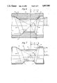
- FIG. 3 is still a further fragmentary view showing connector part dimensional relationships at different temperatures
- FIGS. 4 and 5 are partial schematic views used to illustrate the relative movement between the beveled end walls of the connector body and sleeve during a change in temperature
- FIG. 6 is a cross-sectional view of a second version of the present invention in which the connector is referred to as an assymetrical connector, illustrating in particular the outer connector body;
- FIG. 7 is a side elevation view illustrating the construction of the sleeve used with the outer conductor body of FIG. 6;
- FIG. 8 is a cross-sectional view of the outer conductor body along with the sleeve in an assembled position as in accordance with the version of FIGS. 6 and 7;
- FIG. 10 is a cross-sectional view of the outer conductor body for another embodiment of the invention in which the cone apex is off the center line of the body;
- FIG. 11 is a cross-sectional view of the outer conductor body for still a further embodiment of the invention.
- FIG. 12 is a cross-sectional view of the outer conductor body for still another version of the present invention in which one of the cones is a plane.
- FIG. 1 is a cross-sectional view of a connector embodying the principles of the present invention.
- the connector illustrated in FIG. 1 may be for connection to a printed circuit board although it also has other applications.
- the concepts of the present invention may be employed in connection with the making of any type of connector in which inner and outer conductors are to be relatively supported.
- the principles of the invention may be applied in constructing connectors such as of the general type illustrated in my aforementioned application Ser. No. 579,404.
- the connector illustrated in FIG. 1 comprises a connector body 10 forming an outer conductor, an inner conductor 20 and a Teflon sleeve 30.
- Teflon has good cold flow properties which enable it to be heated to conform to the shape of the inner and outer conductors.
- FIG. 1 illustrates the Teflon sleeve in its final shape. Initially, the Teflon sleeve may be of the size and shape as illustrated in FIG. 5 of application Ser. No. 579,404.
- the Teflon sleeve 30 is assembled into the body 10 so that it extends along the bore length of the body.
- the bore length may be substantially the same length as the length of the Teflon sleeve and may also be the same as the length of the center conductor.
- the next step is assembling of the center conductor into the Teflon sleeve while at the same time maintaining the Teflon sleeve in place in the outer conductor. The assembly operations occur without the application of any heat.
- FIG. 1 illustrates the Teflon having been heated and expanded to essentially fill and match the contour of the inner bore of the outer conductor 10. Also, with respect to the center conductor 20, the Teflon expands about the center conductor and in particular expands into the annular channels that are provided in the center conductor. Thus, the Teflon experiences expansion toward the outer conductor to interlock with the ridge 12 and also experiences inward expansion to interlock with the center conductor and thus provide an overall interlocking between the inner and outer conductors.
- FIGS. 2 and 3 are enlarged fragmentary views of a portion of the connector shown in FIG. 1. These fragmentary views are instrumental in explaining the principles of the present invention as they relate to certain dimensional parameters that are set forth.
- FIGS. 2 and 3 there is provided a fragmentary view illustrating, in particular, the area of the connector at the annular ridge 12 of the outer conductor 10. Between the views of FIGS. 2 and 3 there is illustrated important dimensions including the length L of the ridge 12 and the diameter D which is the mean diameter of the sleeve 30. The drawing also shows the angle ⁇ which is the angle on the beveled end 14 of the ridge 12.
- FIG. 3 in particular, is an expanded fragmentary view of the end of annular ridge 12, showing the changes of part 30 relative to part 10 with a change in temperature.
- the part 10 is considered stationary for the sake of the following derivations.
- the part 30 is shown in solid in connection with its position relating to temperature T 2 and is shown in dotted with relationship to its position in connection with temperature T 1 .
- the outer conductor or part 10 is normally metallic while the inner sleeve or part 30 is an insulator, normally plastic. Most metals have a much lower coefficient of expansion than plastics and thus the following derivation and the geometries of the drawing illustrate that particular case, although, the concepts of the invention will also apply for other combinations of materials including those in which the outer part has a higher coefficient of expansion than the inner part.
- the parts of a connector fabricated in accordance with the present invention maintain mechanical contact and a tight fit over a wide range of temperatures.
- the connector includes a connector body comprising an outer conductor having an axially symmetrical bore with an internal ridge of axial length L and diameter D as shown in FIG. 5.
- the internal ridge is beveled at an angle ⁇ at each end, wherein ⁇ is measured with respect to a plane perpendicular to the axis of the bore.
- a connector insulator having a groove complementary with the internal ridge in the connector body and beveled at an angle ⁇ at each end is positioned in the bore as shown in FIG. 4.
- the insulator When the connector is assembled, the insulator is positioned in the bore of the connector body with the internal ridge of the connector body interengaged with the groove in the insulator.
- the important result is that the parts remain in contact at the beveled ends of the internal ridge and the groove and simply slide relative to each other over these angled surfaces during a temperature change, as illustrated in FIG. 3. Therefore, the parts remain in contact on these angled surfaces even though they do not remain in contact move their nonangled portions due to the differing coefficients of expansion.
- the connector thereby maintains mechanical contact and tight fit between parts over a temperature range in spite of differing coefficients of expansion.
- FIGS. 6 and 7 illustrate the body and sleeve.
- FIG. 8 illustrates these members in an interlock state.
- FIG. 9 is a cross-sectional perspective view showing the connector along with the inner conductor.
- This particular connector design is referred to as an asymmetrical design because the beveled end walls defining the ridge and recess are formed from frusto-conic surfaces of an oblique cone.
- the beveled end wall surfaces in the version illustrated in FIGS. 1-5 are formed from frusto-conic surfaces of a right cone.
- a further asymmetric version is illustrated hereinafter in FIG.
- the frusto-conic surface is also of a right cone.
- the opposed cone surfaces (as represented by elements on the surface thereof) intersect at a single common vertex.
- the frusto-conic surfaces lie on cones having a common vertex.
- the connector illustrated in FIGS. 6-9 is comprised of a connector body 50 forming an outer conductor, an inner conductor 60 and a Teflon sleeve 70.
- Teflon has good cold flow properties which enable it to be heated to conform to the shape of the inner and outer conductors.
- FIG. 8 illustrates the Teflon sleeve in its final position interlocked in the outer conductor. Initially, the Teflon sleeve may be fabricated of smaller sized than illustrated and then heated. In this connection, because of the asymmetrical nature of the construction as illustrated in FIGS.
- the outer conductor and sleeve are aligned circumferentially relative to each other so that there is substantially only one proper alignment position so that the proper length recess interlocks with the proper length ridge.
- the respective parts may be marked for the purpose of providing this circumferential relative alignment
- the Teflon sleeve 70 is assembled into the body 50 so that it extends along the bore length of the body.
- the connector is then heated to a maximum temperature which exceeds the specification for the connector.
- the preferred temperature for heating may be in the order of 160° C. Cold flow is faster at this temperature.
- the Teflon is a good insulator and also has good cold flow characteristics allowing expansion thereof as the heat is applied.
- FIG. 8 illustrates the Teflon having been heated and expanded to partially fill and match the contour of the inner bore of the outer conductor 50.
- FIG. 8 illustrates a gap in FIG. 8.
- the contact surface is at the beveled walls and this is where the mechanical tightness occurs. The gap at remaining areas allows for expansion and contraction but at the beveled walls relative part sliding occurs while always maintaining tight mechanical interlocking over substantial temperature ranges.
- FIG. 6 This illustrates the outer conductor body 50 with its annular ridge 52 defined by opposed beveled end walls 54. These beveled end walls are defined by a frusto-conic surface as indicated at 56 in FIG. 6. These are respective frusto-conic surfaces of oblique cones having a common vertex as illustrated at S in FIG. 6. Reference will be made hereinafter to FIG. 10 in which oblique cones are also illustrated but in which the vertex is off of the center line of the parts. In still a further asymmetric version in FIG. 12, the frusto-conic surface is of a right cone.
- FIG. 7 now illustrates the Teflon sleeve 70 having a recess as indicated at 72 in FIG. 7.
- This recess is similarly defined by opposed beveled end walls 74.
- These end walls define a frusto-conic surface illustrated at 76 in FIG. 7.
- These opposed frusto-conic surfaces are formed from oblique cones each having a common vertex also at the same center point, namely vertex S in FIG. 7.
- the outer conductor or part 50 is normally metallic while the inner sleeve or part 70 is an insulator, normally plastic or Teflon. Both of these materials are typical of isotropic materials. Most metals have a much lower coefficient of expansion than plastics and thus the following derivation and the geometries of the drawing illustrate that particular case, although the concepts of the invention also apply for other combinations of materials including those in which the outer part has a higher coefficient of expansion than the inner part.
- the outer conductor 50 may be considered as having three inner cylindrical bores connected by the two conical surfaces illustrated in FIG. 6 as frusto-conic surfaces 56. When these surfaces are extended, they contain a common vertex, namely point S in FIG. 6. This represents the apex or vertex of each of these cones.
- FIG. 7 illustrates the sleeve 70 which is comprised of essentially three cylinders connected by two conical surfaces, illustrated in FIG. 7 as the frusto-conic surfaces 76. It is noted that these surfaces may be extended to a common point, namely point S in FIG. 7. This is the apex or vertex of the common cones. These cones illustrated in FIGS. 6 and 7 are cones having their vertex at this common point S.
- the outer diameter of the cylinders comprising sleeve 50 have a smaller diameter than the corresponding cylindrical bores of the outer conductor 50.
- the two separate parts, namely the outer conductor 50 and the sleeve 70 are supported substantially only on these conical surfaces, namely the conical surface 56 of the outer conductor 50 and the conical surface 76 of the sleeve 70.
- an arbitrary element of the cone 76 referred to as element J, is selected. It passes through the point S by definition. One may then select an arbitrary line through point S which may be referred to as line SX.
- the line SX need not be coincident with the axis of the internal cylinder defining the outer conductor, although, in practice, that is usually the case and is preferred.
- the plane containing the two intersecting lines J and SX is denoted by JSX. It is this plane, JSX, that is illustrated in FIGS. 6-8.
- the line SY is defined as the line perpendicular to the line SX and through the point S in the JSX plane.
- the lines SX and SY can be considered to be the X and Y axis of the plane JSX. Every element of the cone 56 has such a coordinate system associated with it so that whatever is proved for one element of the cone is proven for every other.
- angle ⁇ which is illustrated as the angle between the X axis and the previously selected element of the cone, namely element J.
- An element of a cone is defined in geometry as a straight line on the conical surface of the cone passing through the vertex.
- the X dimension is a length dimension illustrated in the drawings as measured from the Y axis to a point n on the cone element J. This point coincides with a point on both conical surfaces of the outer conductor and the sleeve. In FIG. 6 the dimension is illustrated as length X 1 relating to the outer conductor while in FIG. 7 this dimension is expressed as dimension X 2 relating to the sleeve.
- a Y dimension also illustrated in the drawings
- the Y dimension is the distance from the point n on the conical surface measured perpendicular to the X axis. In FIG. 6 this dimension is indicated as dimension Y 1 associated with the outer conductor. In FIG. 7 this dimension is dimension Y 2 associated with the sleeve 70.
- the lines joining points n and K 1 has the same slope as the line joining points S and n. Moreover, it coincides with the element of the cone passing through the point n since both lines lie on the same plane, have the same slope and pass through a common point.
- FIGS. 10-12 Reference is now made to further embodiments of the invention illustrated in FIGS. 10-12. These further embodiments of the invention are illustrated for the purpose of showing the various embodiments that are contemplated as falling within the scope of the invention.
- FIGS. 10-12 only the outer conductor is illustrated, it being understood that a corresponding sleeve is provided mating in a manner with the outer conductor body as has been previously illustrated in FIG. 8.
- FIGS. 6-8 it is noted that the apex of the cones falls upon the center line of the parts.
- FIG. 10 has been illustrated to show that the apex of the cone, illustrated in FIG. 10 at S need not fall upon the center line CL of the connector outer conductor.
- FIG. 10 there is illustrated the outer conductor body 61 with its annular ridge 62 defined by opposed beveled end walls 64. These beveled end walls are defined by a frusto-conic surface as illustrated at 66 in FIG. 10. These are respective frusto-conic surfaces of oblique cones having a common vertex at S.
- FIG. 10 also illustrates the point A on the center line CL falling on the Y axis. It is noted that the vertex of the cones at point S does not coincide with point A and does not fall upon the defined center line axis CL.
- FIG. 11 illustrates a further embodiment of the present invention in which the vertex S is disposed on the Y axis.
- both cones have the common vertex point a S and thus the equations previously developed in the derivations set forth hereinbefore also apply to the version of FIG. 11.
- the outer conductor body 80 is illustrated with its annular ridge 82 defined by opposed beveled end walls 84.
- the beveled end walls 84 for example, on the right in FIG. 11 are longer than the corresponding end walls 84 on the left.
- These beveled end walls are defined by a frusto-conic surface as illustrated at 86 in FIG. 11. Again, it is noted that the surface 86 on the right in FIG. 11 is larger than the surface 86 on the left. This has to do with the positioning of the vertex of the respective cones.
- FIG. 12 illustrates still a further version of the present invention in which the point S has now been moved so as to essentially eliminate one of the cones leaving one of the end walls, namely end wall 95 not beveled but instead a right angle end wall.
- the conic surface At the right end in the embodiment of FIG. 12 there is provided the conic surface.
- the ridge 92 is defined by the beveled wall 94 and the end wall 95.
- the embodiment of FIG. 12 illustrates, not an oblique cone as in FIGS. 10 and 11, but instead a right cone. If the apex S were off the center line CL then an embodiment is envisioned in which there is still only one cone but it would then be an oblique cone rather than a right cone.
Abstract
Description
ΔD=D.sub.1.a.ΔT (6)
ΔL=L.sub.1.a.ΔT (7)
ΔD'=D.sub.1 '.b.ΔT (9)
ΔL'=L.sub.1 '.b.ΔT (10)
X.sub.1 '=X.sub.1 (t.sub.2 -t.sub.1)a; Y.sub.1 '=Y.sub.1 (t.sub.2 -t.sub.1)a
m.sub.1 (X.sub.1 (t.sub.2 -t.sub.1)a-X.sub.1)=Y.sub.1 (t.sub.2 -t.sub.1)a-Y.sub.1
Claims (34)
L=D tan θ
Priority Applications (1)
| Application Number | Priority Date | Filing Date | Title |
|---|---|---|---|
| US07/183,974 US4907983A (en) | 1986-05-13 | 1988-04-20 | Electrical connector |
Applications Claiming Priority (2)
| Application Number | Priority Date | Filing Date | Title |
|---|---|---|---|
| US06/864,739 US4775325A (en) | 1985-05-02 | 1986-05-13 | Electrical connector |
| US07/183,974 US4907983A (en) | 1986-05-13 | 1988-04-20 | Electrical connector |
Related Parent Applications (1)
| Application Number | Title | Priority Date | Filing Date |
|---|---|---|---|
| US06/864,739 Continuation-In-Part US4775325A (en) | 1985-05-02 | 1986-05-13 | Electrical connector |
Publications (1)
| Publication Number | Publication Date |
|---|---|
| US4907983A true US4907983A (en) | 1990-03-13 |
Family
ID=26879703
Family Applications (1)
| Application Number | Title | Priority Date | Filing Date |
|---|---|---|---|
| US07/183,974 Expired - Fee Related US4907983A (en) | 1986-05-13 | 1988-04-20 | Electrical connector |
Country Status (1)
| Country | Link |
|---|---|
| US (1) | US4907983A (en) |
Cited By (9)
| Publication number | Priority date | Publication date | Assignee | Title |
|---|---|---|---|---|
| US5453025A (en) * | 1994-02-24 | 1995-09-26 | Redev Management Corp. | Electrical connector |
| EP0677727A2 (en) * | 1994-04-15 | 1995-10-18 | Ssi Technologies, Inc. | Pressure sensor assembly and method of producing the pressure sensor assembly |
| US5811684A (en) * | 1996-04-04 | 1998-09-22 | Ssi Technologies, Inc. | Pressure sensor package and method of making the same |
| US5831170A (en) * | 1996-04-04 | 1998-11-03 | Ssi Technologies, Inc. | Pressure sensor package and method of making the same |
| US5996419A (en) * | 1996-04-04 | 1999-12-07 | Ssi Technologies, Inc. | Pressure sensor package |
| US6752668B2 (en) | 2002-08-14 | 2004-06-22 | Konnektech, Ltd. | Electrical connector |
| US20080311790A1 (en) * | 2007-06-14 | 2008-12-18 | Thomas & Betts International, Inc. | Constant force coaxial cable connector |
| US7614918B1 (en) * | 2008-06-06 | 2009-11-10 | Hon Hai Precision Ind. Co, Ltd. | Cable connector assembly |
| US20220329022A1 (en) * | 2021-04-07 | 2022-10-13 | Bo-Jiang Technology Co., Ltd. | Coaxial connector |
Citations (8)
| Publication number | Priority date | Publication date | Assignee | Title |
|---|---|---|---|---|
| US2590761A (en) * | 1948-03-17 | 1952-03-25 | Gen Electric | Bearing |
| US2984811A (en) * | 1957-02-06 | 1961-05-16 | Bendix Corp | Electrical connector |
| US3107950A (en) * | 1961-01-04 | 1963-10-22 | Rosemount Eng Co Ltd | Bearing |
| US3311431A (en) * | 1964-08-07 | 1967-03-28 | Irving W Hilliard | Temperature compensating bearing assembly |
| US3359047A (en) * | 1965-05-28 | 1967-12-19 | Bell Telephone Labor Inc | Bearing structure |
| US4110716A (en) * | 1976-11-01 | 1978-08-29 | Nikitas Nick C | D.C. block connectors |
| US4360245A (en) * | 1980-07-07 | 1982-11-23 | Delta Electronics Mfg. Corp. | Coaxial connector |
| US4688877A (en) * | 1983-08-18 | 1987-08-25 | Sealectro Corporation | Solderless coaxial connector |
-
1988
- 1988-04-20 US US07/183,974 patent/US4907983A/en not_active Expired - Fee Related
Patent Citations (8)
| Publication number | Priority date | Publication date | Assignee | Title |
|---|---|---|---|---|
| US2590761A (en) * | 1948-03-17 | 1952-03-25 | Gen Electric | Bearing |
| US2984811A (en) * | 1957-02-06 | 1961-05-16 | Bendix Corp | Electrical connector |
| US3107950A (en) * | 1961-01-04 | 1963-10-22 | Rosemount Eng Co Ltd | Bearing |
| US3311431A (en) * | 1964-08-07 | 1967-03-28 | Irving W Hilliard | Temperature compensating bearing assembly |
| US3359047A (en) * | 1965-05-28 | 1967-12-19 | Bell Telephone Labor Inc | Bearing structure |
| US4110716A (en) * | 1976-11-01 | 1978-08-29 | Nikitas Nick C | D.C. block connectors |
| US4360245A (en) * | 1980-07-07 | 1982-11-23 | Delta Electronics Mfg. Corp. | Coaxial connector |
| US4688877A (en) * | 1983-08-18 | 1987-08-25 | Sealectro Corporation | Solderless coaxial connector |
Cited By (12)
| Publication number | Priority date | Publication date | Assignee | Title |
|---|---|---|---|---|
| US5453025A (en) * | 1994-02-24 | 1995-09-26 | Redev Management Corp. | Electrical connector |
| EP0677727A2 (en) * | 1994-04-15 | 1995-10-18 | Ssi Technologies, Inc. | Pressure sensor assembly and method of producing the pressure sensor assembly |
| EP0677727A3 (en) * | 1994-04-15 | 1996-08-07 | Ssi Technologies Inc | Pressure sensor assembly and method of producing the pressure sensor assembly. |
| US5811684A (en) * | 1996-04-04 | 1998-09-22 | Ssi Technologies, Inc. | Pressure sensor package and method of making the same |
| US5831170A (en) * | 1996-04-04 | 1998-11-03 | Ssi Technologies, Inc. | Pressure sensor package and method of making the same |
| US5874679A (en) * | 1996-04-04 | 1999-02-23 | Ssi Technologies, Inc. | Pressure sensor package and method of making the same |
| US5996419A (en) * | 1996-04-04 | 1999-12-07 | Ssi Technologies, Inc. | Pressure sensor package |
| US6752668B2 (en) | 2002-08-14 | 2004-06-22 | Konnektech, Ltd. | Electrical connector |
| US20080311790A1 (en) * | 2007-06-14 | 2008-12-18 | Thomas & Betts International, Inc. | Constant force coaxial cable connector |
| US7614918B1 (en) * | 2008-06-06 | 2009-11-10 | Hon Hai Precision Ind. Co, Ltd. | Cable connector assembly |
| US20220329022A1 (en) * | 2021-04-07 | 2022-10-13 | Bo-Jiang Technology Co., Ltd. | Coaxial connector |
| US11588283B2 (en) * | 2021-04-07 | 2023-02-21 | Bo-Jiang Technology Co., Ltd. | Coaxial connector |
Similar Documents
| Publication | Publication Date | Title |
|---|---|---|
| US4520229A (en) | Splice connector housing and assembly of cables employing same | |
| US5993254A (en) | Connector for coaxial cables with improved contact-making between connector head and outer cable connector | |
| US4687272A (en) | Device for pressure sealed connection of the outer conductor of a coaxial line | |
| US4334730A (en) | Insulated from ground bulkhead adapter | |
| US3390374A (en) | Coaxial connector with cable locking means | |
| US4907983A (en) | Electrical connector | |
| US4557538A (en) | Assembly for effecting an electric connection through a pipe formed of several elements | |
| US5267877A (en) | Coaxial connector for corrugated conduit | |
| US4698458A (en) | Joint for cables with an extruded insulation | |
| JP3534235B2 (en) | Braided shielded wire connector | |
| JPS6293875A (en) | Compression pressure indicator | |
| US20010034159A1 (en) | Connector for coaxial cables with thin-walled outer cable conductor | |
| US20040100160A1 (en) | Drum commutator and method for producing the same | |
| GB2299467A (en) | Connector for a hollow center conductor of a radio frequency cable | |
| EP0472520A4 (en) | Electrical connector | |
| US4543548A (en) | Coaxial transmission line having an expandable and contractible bellows | |
| US3579282A (en) | Transmission line connector with means including cam surfaces for altering connector element dimensions to compensate for junction gaps, and method therefor | |
| US5115563A (en) | Method of making an electrical connector | |
| US4971578A (en) | Electrical connector | |
| US4707047A (en) | Environmentally sealed electrical connector | |
| US3233202A (en) | Multiple contact connector | |
| US3266006A (en) | Temperature-compensated clamp seal | |
| US4920643A (en) | Method of assembling electrical connector | |
| US4641909A (en) | Plug connector | |
| JPH0760718B2 (en) | Electrical connector |
Legal Events
| Date | Code | Title | Description |
|---|---|---|---|
| AS | Assignment |
Owner name: MICROWAVE DEVELOPMENT LABORATORIES, 135 CRESCENT S Free format text: ASSIGNMENT OF ASSIGNORS INTEREST.;ASSIGNOR:WILSON, RONALD A.;REEL/FRAME:004901/0304 Effective date: 19880524 Owner name: MICROWAVE DEVELOPMENT LABORATORIES, A MA CORP.,MAS Free format text: ASSIGNMENT OF ASSIGNORS INTEREST;ASSIGNOR:WILSON, RONALD A.;REEL/FRAME:004901/0304 Effective date: 19880524 |
|
| FEPP | Fee payment procedure |
Free format text: PAYOR NUMBER ASSIGNED (ORIGINAL EVENT CODE: ASPN); ENTITY STATUS OF PATENT OWNER: SMALL ENTITY |
|
| FPAY | Fee payment |
Year of fee payment: 4 |
|
| AS | Assignment |
Owner name: REDEV MANAGEMENT CORPORATION, NEW HAMPSHIRE Free format text: ASSIGNMENT OF ASSIGNORS INTEREST;ASSIGNOR:MICROWAVE DEVELOPMENT LABORATORIES, INC.;REEL/FRAME:007648/0360 Effective date: 19950602 |
|
| FPAY | Fee payment |
Year of fee payment: 8 |
|
| FEPP | Fee payment procedure |
Free format text: PAYER NUMBER DE-ASSIGNED (ORIGINAL EVENT CODE: RMPN); ENTITY STATUS OF PATENT OWNER: SMALL ENTITY Free format text: PAYOR NUMBER ASSIGNED (ORIGINAL EVENT CODE: ASPN); ENTITY STATUS OF PATENT OWNER: SMALL ENTITY |
|
| FEPP | Fee payment procedure |
Free format text: PAYER NUMBER DE-ASSIGNED (ORIGINAL EVENT CODE: RMPN); ENTITY STATUS OF PATENT OWNER: SMALL ENTITY Free format text: PAYOR NUMBER ASSIGNED (ORIGINAL EVENT CODE: ASPN); ENTITY STATUS OF PATENT OWNER: SMALL ENTITY |
|
| REMI | Maintenance fee reminder mailed | ||
| LAPS | Lapse for failure to pay maintenance fees | ||
| STCH | Information on status: patent discontinuation |
Free format text: PATENT EXPIRED DUE TO NONPAYMENT OF MAINTENANCE FEES UNDER 37 CFR 1.362 |
|
| FP | Lapsed due to failure to pay maintenance fee |
Effective date: 20020313 |