US4901889A - Apparatus for mounting a tissue roll and dispensing a flowable substance - Google Patents
Apparatus for mounting a tissue roll and dispensing a flowable substance Download PDFInfo
- Publication number
- US4901889A US4901889A US07/298,121 US29812189A US4901889A US 4901889 A US4901889 A US 4901889A US 29812189 A US29812189 A US 29812189A US 4901889 A US4901889 A US 4901889A
- Authority
- US
- United States
- Prior art keywords
- canister
- handle
- passage
- nozzle
- dispensing
- Prior art date
- Legal status (The legal status is an assumption and is not a legal conclusion. Google has not performed a legal analysis and makes no representation as to the accuracy of the status listed.)
- Expired - Lifetime
Links
Images
Classifications
-
- B—PERFORMING OPERATIONS; TRANSPORTING
- B65—CONVEYING; PACKING; STORING; HANDLING THIN OR FILAMENTARY MATERIAL
- B65D—CONTAINERS FOR STORAGE OR TRANSPORT OF ARTICLES OR MATERIALS, e.g. BAGS, BARRELS, BOTTLES, BOXES, CANS, CARTONS, CRATES, DRUMS, JARS, TANKS, HOPPERS, FORWARDING CONTAINERS; ACCESSORIES, CLOSURES, OR FITTINGS THEREFOR; PACKAGING ELEMENTS; PACKAGES
- B65D83/00—Containers or packages with special means for dispensing contents
- B65D83/14—Containers or packages with special means for dispensing contents for delivery of liquid or semi-liquid contents by internal gaseous pressure, i.e. aerosol containers comprising propellant for a product delivered by a propellant
- B65D83/38—Details of the container body
- B65D83/384—Details of the container body comprising an aerosol container disposed in an outer shell or in an external container
-
- A—HUMAN NECESSITIES
- A47—FURNITURE; DOMESTIC ARTICLES OR APPLIANCES; COFFEE MILLS; SPICE MILLS; SUCTION CLEANERS IN GENERAL
- A47K—SANITARY EQUIPMENT NOT OTHERWISE PROVIDED FOR; TOILET ACCESSORIES
- A47K10/00—Body-drying implements; Toilet paper; Holders therefor
- A47K10/24—Towel dispensers, e.g. for piled-up or folded textile towels; Toilet-paper dispensers; Dispensers for piled-up or folded textile towels provided or not with devices for taking-up soiled towels as far as not mechanically driven
- A47K10/32—Dispensers for paper towels or toilet-paper
-
- B—PERFORMING OPERATIONS; TRANSPORTING
- B65—CONVEYING; PACKING; STORING; HANDLING THIN OR FILAMENTARY MATERIAL
- B65D—CONTAINERS FOR STORAGE OR TRANSPORT OF ARTICLES OR MATERIALS, e.g. BAGS, BARRELS, BOTTLES, BOXES, CANS, CARTONS, CRATES, DRUMS, JARS, TANKS, HOPPERS, FORWARDING CONTAINERS; ACCESSORIES, CLOSURES, OR FITTINGS THEREFOR; PACKAGING ELEMENTS; PACKAGES
- B65D83/00—Containers or packages with special means for dispensing contents
- B65D83/14—Containers or packages with special means for dispensing contents for delivery of liquid or semi-liquid contents by internal gaseous pressure, i.e. aerosol containers comprising propellant for a product delivered by a propellant
- B65D83/28—Nozzles, nozzle fittings or accessories specially adapted therefor
-
- A—HUMAN NECESSITIES
- A47—FURNITURE; DOMESTIC ARTICLES OR APPLIANCES; COFFEE MILLS; SPICE MILLS; SUCTION CLEANERS IN GENERAL
- A47K—SANITARY EQUIPMENT NOT OTHERWISE PROVIDED FOR; TOILET ACCESSORIES
- A47K10/00—Body-drying implements; Toilet paper; Holders therefor
- A47K10/24—Towel dispensers, e.g. for piled-up or folded textile towels; Toilet-paper dispensers; Dispensers for piled-up or folded textile towels provided or not with devices for taking-up soiled towels as far as not mechanically driven
- A47K10/32—Dispensers for paper towels or toilet-paper
- A47K2010/322—Dispensers for paper towels or toilet-paper with means for deodorizing the ambient air
-
- A—HUMAN NECESSITIES
- A47—FURNITURE; DOMESTIC ARTICLES OR APPLIANCES; COFFEE MILLS; SPICE MILLS; SUCTION CLEANERS IN GENERAL
- A47K—SANITARY EQUIPMENT NOT OTHERWISE PROVIDED FOR; TOILET ACCESSORIES
- A47K10/00—Body-drying implements; Toilet paper; Holders therefor
- A47K10/24—Towel dispensers, e.g. for piled-up or folded textile towels; Toilet-paper dispensers; Dispensers for piled-up or folded textile towels provided or not with devices for taking-up soiled towels as far as not mechanically driven
- A47K10/32—Dispensers for paper towels or toilet-paper
- A47K2010/3266—Wet wipes
- A47K2010/3273—Wet wipes moistened just before use
-
- Y—GENERAL TAGGING OF NEW TECHNOLOGICAL DEVELOPMENTS; GENERAL TAGGING OF CROSS-SECTIONAL TECHNOLOGIES SPANNING OVER SEVERAL SECTIONS OF THE IPC; TECHNICAL SUBJECTS COVERED BY FORMER USPC CROSS-REFERENCE ART COLLECTIONS [XRACs] AND DIGESTS
- Y10—TECHNICAL SUBJECTS COVERED BY FORMER USPC
- Y10S—TECHNICAL SUBJECTS COVERED BY FORMER USPC CROSS-REFERENCE ART COLLECTIONS [XRACs] AND DIGESTS
- Y10S242/00—Winding, tensioning, or guiding
- Y10S242/905—Winder with storage chamber, e.g. for deodorant, paper
Definitions
- the present invention relates to a mounting apparatus for mounting a roll of tissue in a wall fixture or the like and which incorporates means for dispensing a flowable substance.
- Such a mounting apparatus has previously been proposed, for example, in Glaner U.S. Pat. No. 3,151,822. That patent discloses an aerosol canister having a pair of support members mounted thereon at opposite ends. A first of the support members is mounted on the canister body, and the second is mounted directly on the canister nozzle. Each support member carries a hub which is insertable into a corresponding recess of a wall fixture. When the apparatus is inserted into the center core of a conventional toilet tissue roll, the hubs project beyond the axial ends of the roll and are thus insertable into the fixture recesses. To facilitate such insertion, the first support member is resiliently biased axially outwardly by a coil spring. Once inserted, the nozzle can be actuated to spray deodorant by axially depressing the second support member, whereupon the deodorant travels through a lateral passage formed int he second support member.
- the apparatus since part of the combined weight of the canister and tissue roll is borne by the canister nozzle, the apparatus might not be usable with the type of canister which is actuated by a radial (as opposed to axial) depression of the nozzle, since the vertical forces acting on the nozzle for supporting the load might produce inadvertent dispensing of fluid.
- tissue support/fluid dispenser Another type of tissue support/fluid dispenser is disclosed in Wardell, Jr. U.S. Pat. No. 2,746,898.
- the deodorant spray is emitted in the longitudinal direction of the canister.
- the canister must be suspended away from the wall in order to be actuable. That is, such apparatus cannot be installed in the customary manner within a wall fixture.
- the present invention envisions a dispenser capable of dispensing a foam, such as a cleansing foam.
- a foamable liquid is discharged from the canister. That is, the liquid would exit the discharge handle at high speed against the receiving object, such as toilet tissue held by the user, and may rebound from that object in a manner making a mess.
- the present invention involves an apparatus for rotatably mounting a roll of tissue in a holder and for dispensing a flowable substance.
- the apparatus comprises a canister including a body which contains a flowable substance under pressure, and a discharge nozzle at one end of the body.
- the canister is adapted to be coaxially disposed within a core of a tissue roll.
- a support structure is mounted on the canister body and includes first and second support members disposed at opposite ends of the canister body. Those support members carry first and second mounting structures, respectively, such as axially projecting hubs which are coaxially and rotatably mountable in a holder.
- a dispensing handle is mounted on a second support member and extends laterally outwardly therefrom.
- the handle includes an aperture receiving the canister nozzle, and a passage extending laterally of the aperture. One end of the passage communicates with the aperture and another end of the passage defines an outlet opening adjacent an outer end of the handle.
- the dispensing handle is movable relative to the second support member to cause the canister nozzle to be depressed and emit a flowable substance which travels through the passage and exits through the discharge outlet.
- the passage in the handle includes an expansion chamber disposed immediately upstream of the discharge outlet to reduce the speed of a foamable substance emitted from the canister, and thereby produce a gentler discharge of that substance.
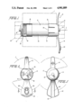
- FIG. 1 is a side elevational view of an apparatus according to the present invention, with one end thereof broken away, and with a tissue roll shown in phantom;
- FIG. 2 is an end view of an apparatus depicted in FIG. 1;
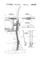
- FIG. 3 is an opposite end view of the apparatus of FIG. 1;
- FIG. 4 is a longitudinal sectional view through a fluid dispensing end of the apparatus, depicting the apparatus in a fluid dispensing mode of operation;
- FIG. 5 is an end view of a dispensing handle according to the present invention.
- FIG. 6 is an end view of a modified form of the dispensing handle
- FIG. 7 is a side elevational view of a locking member according to the present invention.
- FIG. 8 is a front view of the locking member depicted in FIG. 7;
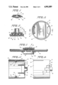
- FIG. 9 is a sectional view taken through the lower end of the dispensing handle depicted in FIG. 5;
- FIG. 10 is a cross-sectional view taken along the line 10--10 in FIG. 2;
- FIG. 11 is a cross-sectional view taken along the line 11--11 in FIG. 2;
- FIG. 12 is an end view of a support sleeve according to the present invention.
- FIG. 13 is a longitudinal sectional view taken through the support sleeve depicted in FIG. 12;
- FIG. 14 is a side elevational view of the support sleeve depicted in FIG. 13;
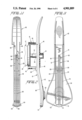
- FIG. 15 is a side elevational view of a front half of the dispensing handle
- FIG. 16 is a side elevational view of a rear half of the dispensing handle.
- FIG. 17 is a longitudinal sectional view similar to FIG. 4, with the dispensing handle in a locked, nondispensing mode.
- a mounting apparatus 10 for a roll of toilet tissue T comprises a canister 12, a pair of sleeves 14, 16 mounted at opposite ends of the canister 12, and a manually actuable dispensing handle 18 disposed in one of the sleeves 16 and movable relative thereto to dispense a fluid from the canister.
- the canister can be of a conventional type which includes a cylindrical body 20 and a dispensing nozzle 22.
- the body contains a fluid under pressure, e.g., an aerosol canister.
- the fluid may be of any suitable type including a foamable cleansing liquid which includes a soap or emulsion.
- the nozzle 22 extends axially and emits liquid in response to a radial depression of the outer end of the nozzle as indicated by the arrow A in FIG. 4.
- the sleeves 14, 16 are of generally hollow cylindrical construction and have axially alignable recesses for receiving respective ends of the canister body 20.
- the sleeves carry axially outwardly extending cylindrical hubs 24 which are coaxial and adapted to be received in the recesses of a standard wall-mounted holder or fixture 26.
- a first of the sleeves 14 includes a recess 29 which telescopingly receives an end 28 of the container which is remote from the nozzle 22.
- That recess 29 contains a spring 30, such as a block of elastic material, i.e., a material which returns to its initial form after being compressed.
- the spring 30 acts between the sleeve 14 and the canister body 20 to bias the sleeve axially outwardly in order to facilitate the insertion and removal of the apparatus relative to the holder.
- the second sleeve 16 is formed with two pairs of circumferentially spaced, axially extending slits 32 which define a pair of flexible latching elements 34 (see FIGS. 12-14) which can be flexed relative to the remaining or main portion 35 of the sleeve 16.
- Each of those elements 34 carries a radially inwardly projecting curved lug 36 adapted to be received within an annular groove 38 in the outer periphery of the canister body for retaining the sleeve 16 axially immovably on the canister body. By prying the elements 34 radially outwardly, the sleeve 16 can be removed from the canister.
- Opposite sides 40, 42 of each lug are inclined to define cammable surfaces which facilitate insertion of the lugs into and from the groove 38.
- the main portion 35 of the second sleeve 16 includes a pair of walls 44 (FIGS. 12, 13) which rigidify that main portion 35.
- Formed in the main portion 35 of the sleeve 16 is a pair of diametrically opposed slots 46, 48 (FIGS. 2, 13, 14, 17) which are disposed in vertically superposed relationship when the apparatus is in an installed condition.
- a lower one of the slots 48 (FIG. 14) is T-shaped, whereas the upper slot 46 (FIG. 13) is rectangular.
- the slots are sized to receive the dispensing handle 18.
- the handle 18 extends laterally relative to the common axis L defined by the hubs 24. When the apparatus is installed, the axis L extends horizontally and the handle 18 extends vertically.
- a front side of the handle carries a hollow projection 50 disposed within a recess 49 defined by the sleeve 16. That projection 50 forms an aperture 51 which receives the nozzle 22 with a relatively snug fit.
- Extending along the length of the handle 18 is a passage 52 (see FIG. 4) which communicates with the aperture 51 at its upper end and terminates in a discharge outlet 54 at its lower end.
- the lower slot 48 is sized to permit the handle to be moved relative to the sleeve 16 toward and away from the canister 12. That is, by manually applying a force to the lower portion of the handle, causing the handle to be rotated in direction B (see FIG.
- the nozzle 22 will be depressed radially in direction A to emit pressurized liquid. That liquid will travel through the aperture 51 and the passage 52 and be discharged through the outlet 54.
- FIGS. 15, 16, 10 and 11 Depicted in FIGS. 15, 16, 10 and 11 is a rib arrangement which can be integrally molded with the handle and which defines the passage 52.
- the handle 18 comprises front and rear halves 60, 62 which are secured together.
- the rear half 62 (FIG. 6) comprises a plate portion 64 having a first upstanding rib 66 which includes a pair of parallel portions 68 interconnected at their upper ends by a bight portion 70.
- the upper portion of the handle projects beyond the sleeve 16 by a distance sufficient to prevent the apparatus 10 from being rotated in a direction causing the lower end of the handle to be raised. That is, if during the removal of tissue from the roll forces are applied to the apparatus in a direction tending to rotate the apparatus counterclockwise as viewed in FIG. 2, the top portion of the handle 18 would engage the back wall of the holder 26 to prevent any appreciable rotation of the apparatus. Thus, it is assured that the handle dispensing outlet (to be described hereinafter) will always point downwardly).
- a groove 72 is defined between the parallel portions 68. Extending at a right angle from the lower end of each parallel portion 68 is a foot 74 which terminates in a slightly downwardly inclined toe 76. Second and third parallel ribs 78 are spaced outwardly from the first rib 66 and extend to a greater height from the plate portion 64 than the first rib 66 (see FIG. 10).
- the handle front half 60 comprises a plate portion 90 from which a fourth rib 92 projects.
- the rib 92 includes a pair of parallel portions 94 interconnected by a bight portion 96.
- a port 98 extends through the plate portion 90 in communication with the aperture 51 (see FIG. 10).
- Extending parallel to the rib portions 95 midway therebetween is a fifth rib 98 which is of shorter height than the rib portions 94 as can be seen in FIGS. 10, 11.
- the fifth rib 98 terminates in spaced relationship from the port 98.
- sixth and seventh parallel ribs 100 disposed along the edges of the plate portion 90.
- Extending across the front end of the plate portion 90 is an eighth rib 102 which is joined to lower ends of the ribs 92, 100 in a manner forming a space 104 therebetween.
- Projecting through the eighth rib 102 is a plurality of downwardly extending discharge channels 106 which communicate with the space 104 and which define the discharge outlet.
- the channels 106 are of rectangular cross-section and are arranged in a row (see FIG. 5).
- the channels 106A could be arranged in other patterns, such as a circular pattern in an appropriately shaped handle 18A (see FIG. 6).
- the width of the rib 102 widens toward the center, whereby the lengths of the channels 106 become longer toward the center.
- the front half 60 is configured to mate with the rear half 62 in the manner depicted in FIGS. 3, 10 and 11 wherein the seventh and eighth ribs 100 lie to the inside of the ribs 78; the rib portions 94 lie just to the outside of the rib portions 68; and the fifth rib lies in the groove 52.
- the bight portion 70 lies just to the inside of the bight portion 96 (an outer radius of the former corresponds to the inner radius of the latter).
- the port 98 is spaced from the bight portion 96 by a distance greater than the width of the bight portion 70 so as to remain unblocked.
- the groove 72 and the outer surface of the rib 98 form the passage 52 which communicates with the port 98 to conduct liquid from the nozzle 51 to the discharge channels 106.
- the port 98 is preferably of diminishing cross-section in a direction away from the nozzle.
- the outlet of the port is of smaller cross-section than the passage 52 so a slight reduction of speed of the liquid occurs as the liquid enters the passage 52.
- the liquid begins to foam to some extent as soon as it leaves the cannister. However, it remains in a condensed state, i.e., part foam, part liquid, as it travels along the passage 52 since it is confined in that passage.
- the feet 74 of the rear half 62 fit into the space 104 of the front half 60 in a manner forming an expansion chamber 110 immediately upstream of the discharge channels 106, as depicted in FIG. 9.
- the total cross-section of that chamber 110 is greater than the cross-section of the passage 52, whereby the foamable substance slows as it enters the expansion chamber 110 and virtually completes the conversion to foam, the foam then being pushed through the discharge channels 106.
- the foam exits in a relatively gentle manner, avoiding a high-speed rebound off tissue being held beneath the discharge channels.
- the handle be capable of being locked against actuation to inhibit unauthorized use by small children.
- the lock comprises a circular actuator tab 122 from which extend a pair of parallel legs 124. Each leg terminates in a lug 126.
- the actuator tab 12 is disposed on the rear side of the handle, with the legs 124 extending into the interior of the handle through a pair of slots 128 formed in the rear half 62 of the handle (see FIG. 2).
- the lugs 126 project forwardly through two slots 130 formed in the front handle half 60.
- the lugs 126 When the tab 122 and thus the lugs 126, are in the lowermost position, the lugs will be disposed opposite a pair of shoulders 132 forming the slot 48, as depicted in phantom lines in FIG. 14 and in solid lines in FIG. 17. Hence, the handle cannot be displaced toward the canister 12 to actuate the nozzle. By sliding the tab 122 upwardly, the lugs 126 will be located above the shoulders 132 (see FIG. 4), whereby actuation of the nozzle is possible. The lock is held in the upper or unlocked position by friction.
- the handle 18 is inserted into the sleeve 16 through the lower slot 48.
- the T-shape of that slot accommodates the projection 50 of the handle.
- the sleeve With the projection 50 centered within the recess 49 of the sleeve 16, the sleeve is inserted onto the canister such that the lugs 36 snap into the canister groove 38, and the canister nozzle 22 enters the aperture 51 (see FIG. 17).
- the other sleeve 14 is inserted onto the opposite end of the canister and is depressed to enable the hubs 24 to be inserted into the recesses of a standard holder or fixture 26, with the handle 18 oriented vertically. Since this insertion is achieved without causing the handle 18 to be depressed, there is no risk of accidentally dispensing foam.
- the tab 122 is placed in the unlock mode, and the user pushes against the lower end of the handle to produce rotation thereof in a direction B toward the nozzle (FIG. 4), whereupon the nozzle is radially depressed to emit foamable liquid.
- the user can perform this function with a thumb while holding tissue T beneath the handle (see FIG. 4).
- the liquid travels downwardly through the passage 52 and exits the discharge channels.
- the expansion of the liquid in the chamber 110 just prior to exiting the discharge channels results in a slowdown thereof and a gentle exiting of foam onto the tissue.
- the risk of the foam deflecting from the tissue is reduced.
- the sleeve 16 could be permanently affixed to the canister, whereby the entire apparatus 10 would be replaced when the canister has been emptied.
- the sleeve 16 could be made readily removable (by prying out the flexible elements 34) to enable the user to replace only the canister.
- the canister has been disclosed as having a nozzle which is actuable upon being radially depressed, the canister could, if desired, be provided with a nozzle which is actuated upon being axially depressed.
- the present apparatus can also be used in connection with a canister which contains a non-pressurized flowable substance, e.g., a lotion, in which the handle is oscillated repeatedly in order to pump the lotion from the canister.
- a non-pressurized flowable substance e.g., a lotion
- the handle is oscillated repeatedly in order to pump the lotion from the canister.
- the presence of an expansion chamber immediately upstream of the discharge channels would probably be eliminated.
Abstract
Description
Claims (20)
Priority Applications (8)
| Application Number | Priority Date | Filing Date | Title |
|---|---|---|---|
| US07/298,121 US4901889A (en) | 1989-01-18 | 1989-01-18 | Apparatus for mounting a tissue roll and dispensing a flowable substance |
| CA002005803A CA2005803C (en) | 1989-01-18 | 1989-12-18 | Apparatus for mounting a tissue roll and dispensing a flowable substance |
| MX019041A MX166565B (en) | 1989-01-18 | 1990-01-08 | APPARATUS FOR MOVING A ROLL OF PAPER ROTATELY IN A CLIP OR HOLDER AND TO PROVIDE A FLUID SUBSTANCE |
| ES90300260T ES2053093T3 (en) | 1989-01-18 | 1990-01-10 | APPARATUS FOR ROTALLY MOUNTING A PAPER ROLL ON A BRACKET AND FOR DISTRIBUTING A FLUID SUBSTANCE. |
| EP90300260A EP0379299B1 (en) | 1989-01-18 | 1990-01-10 | Apparatus for mounting a tissue roll and dispensing a flowable susbstance |
| DE69007304T DE69007304T2 (en) | 1989-01-18 | 1990-01-10 | Device for holding a toilet paper roll and dispensing a liquid substance. |
| JP463690A JP2799211B2 (en) | 1989-01-18 | 1990-01-16 | Apparatus for installing tee rolls and distributing fluid material |
| HK98107019A HK1007678A1 (en) | 1989-01-18 | 1998-06-26 | Apparatus for mounting a tissue roll and dispensing a flowable substance |
Applications Claiming Priority (1)
| Application Number | Priority Date | Filing Date | Title |
|---|---|---|---|
| US07/298,121 US4901889A (en) | 1989-01-18 | 1989-01-18 | Apparatus for mounting a tissue roll and dispensing a flowable substance |
Publications (1)
| Publication Number | Publication Date |
|---|---|
| US4901889A true US4901889A (en) | 1990-02-20 |
Family
ID=23149138
Family Applications (1)
| Application Number | Title | Priority Date | Filing Date |
|---|---|---|---|
| US07/298,121 Expired - Lifetime US4901889A (en) | 1989-01-18 | 1989-01-18 | Apparatus for mounting a tissue roll and dispensing a flowable substance |
Country Status (8)
| Country | Link |
|---|---|
| US (1) | US4901889A (en) |
| EP (1) | EP0379299B1 (en) |
| JP (1) | JP2799211B2 (en) |
| CA (1) | CA2005803C (en) |
| DE (1) | DE69007304T2 (en) |
| ES (1) | ES2053093T3 (en) |
| HK (1) | HK1007678A1 (en) |
| MX (1) | MX166565B (en) |
Cited By (24)
| Publication number | Priority date | Publication date | Assignee | Title |
|---|---|---|---|---|
| US5435465A (en) * | 1992-04-28 | 1995-07-25 | El-Amin; Hassan A. | Hygiene device |
| WO2000000071A1 (en) | 1998-06-30 | 2000-01-06 | The Procter & Gamble Company | Apparatus for dispensing tissue |
| WO2001042117A1 (en) * | 1999-12-13 | 2001-06-14 | Irwin Aram J | Combined fluid and pop-up sheet product dispensing system |
| US6382552B1 (en) | 2000-05-24 | 2002-05-07 | The Procter & Gamble Company | Moist tissue dispenser |
| WO2002043546A1 (en) | 2000-11-28 | 2002-06-06 | The Procter & Gamble Company | Dispensing apparatus |
| US6446808B1 (en) | 2000-05-25 | 2002-09-10 | The Procter & Gamble Company | Dispenser for moist tissue |
| US6457893B1 (en) | 2001-08-13 | 2002-10-01 | George Wesley Hamilton | Personal hygiene device for moistening tissue |
| US6688551B1 (en) | 2002-11-15 | 2004-02-10 | The Dial Corporation | Methods and apparatus for toilet paper roll holder vapor dispenser |
| US20040124101A1 (en) * | 2002-12-31 | 2004-07-01 | Joseph Mitchell | Disposable dispenser with fragrance delivery system |
| US20050082314A1 (en) * | 2003-10-21 | 2005-04-21 | Macierowski Glenn E. | Spray actuator collar for spray canisters |
| US6918513B1 (en) * | 2004-04-05 | 2005-07-19 | Kevin Downey | Toilet tissue dispenser with liquid spray |
| US20070290092A1 (en) * | 2006-06-14 | 2007-12-20 | Haion Won | Toilet tissue holder and dispenser |
| US20110042486A1 (en) * | 2009-08-18 | 2011-02-24 | Lee Luft | Cleaning tool |
| US20110284567A1 (en) * | 2010-05-21 | 2011-11-24 | Donald Hatter | Inner wipes |
| US20110315715A1 (en) * | 2010-06-25 | 2011-12-29 | Heiner Ophardt | Combined Toilet paper and fluid dispenser |
| US20140103133A1 (en) * | 2012-10-15 | 2014-04-17 | Todd Muderlak | Web-Material Dispenser With Air Freshener |
| US20140246535A1 (en) * | 2006-03-27 | 2014-09-04 | Sca Hygiene Products Ab | End plug for a paper roll |
| US20150001332A1 (en) * | 2013-06-29 | 2015-01-01 | Jimmy Qin | Pet Waste Bag Kit |
| US20150196173A1 (en) * | 2014-01-10 | 2015-07-16 | The Procter & Gamble Company | Wet/dry sheet dispenser and method of using |
| US20150366416A1 (en) * | 2014-06-20 | 2015-12-24 | The Procter & Gamble Company | Wet/dry sheet dispenser with dispensing cup |
| US9975660B2 (en) * | 2014-10-13 | 2018-05-22 | Handipod Limited | Container and dispensing device |
| US10238243B1 (en) | 2016-04-13 | 2019-03-26 | Sue A Coulston | Wiping solution band dispenser |
| US20200015638A1 (en) * | 2018-07-12 | 2020-01-16 | Gpcp Ip Holdings Llc | Sheet product roll holder with integrated flowable material dispensing mechanism |
| US10875039B1 (en) | 2016-04-13 | 2020-12-29 | Sue A Coulston | Wiping solution band dispenser |
Families Citing this family (2)
| Publication number | Priority date | Publication date | Assignee | Title |
|---|---|---|---|---|
| JP4234456B2 (en) * | 2003-01-31 | 2009-03-04 | 花王株式会社 | Fragrance equipment |
| CN111568281B (en) * | 2020-06-17 | 2021-06-18 | 季新年 | Dry and wet dual-purpose tissue box with disinfectant |
Citations (9)
| Publication number | Priority date | Publication date | Assignee | Title |
|---|---|---|---|---|
| US2639939A (en) * | 1951-10-08 | 1953-05-26 | Henry I Matchett | Deodorizing toilet paper holder |
| US2746798A (en) * | 1955-05-18 | 1956-05-22 | Jr Macarthur Wardell | Deodorant spray toilet paper hanger |
| US3151822A (en) * | 1962-02-27 | 1964-10-06 | Louis O Glaner | Paper and deodorant dispenser |
| US3336603A (en) * | 1965-06-22 | 1967-08-22 | Ragnvald G Leland | Toilet bowldeodorizer |
| US3608785A (en) * | 1969-12-18 | 1971-09-28 | August J Durso | Aerosol container and closure cap unit therefor |
| US3848822A (en) * | 1973-06-04 | 1974-11-19 | P Boone | Dispensing device |
| US4226340A (en) * | 1978-08-15 | 1980-10-07 | Louis Troesch | Tissue treatment dispenser |
| US4436224A (en) * | 1982-02-22 | 1984-03-13 | Mcinerny John | Dispenser for fluids and paper towels |
| US4759510A (en) * | 1987-07-06 | 1988-07-26 | Singer Monroe J | Universal scent-emitting toilet paper roller |
Family Cites Families (2)
| Publication number | Priority date | Publication date | Assignee | Title |
|---|---|---|---|---|
| US1582645A (en) * | 1923-01-29 | 1926-04-27 | William F Findley | Combination liquid-soap dispenser and towel rack |
| US3910229A (en) * | 1974-07-30 | 1975-10-07 | Henry C Spencer | Toilet roll paper moistening device |
-
1989
- 1989-01-18 US US07/298,121 patent/US4901889A/en not_active Expired - Lifetime
- 1989-12-18 CA CA002005803A patent/CA2005803C/en not_active Expired - Fee Related
-
1990
- 1990-01-08 MX MX019041A patent/MX166565B/en unknown
- 1990-01-10 DE DE69007304T patent/DE69007304T2/en not_active Expired - Fee Related
- 1990-01-10 EP EP90300260A patent/EP0379299B1/en not_active Expired - Lifetime
- 1990-01-10 ES ES90300260T patent/ES2053093T3/en not_active Expired - Lifetime
- 1990-01-16 JP JP463690A patent/JP2799211B2/en not_active Expired - Fee Related
-
1998
- 1998-06-26 HK HK98107019A patent/HK1007678A1/en not_active IP Right Cessation
Patent Citations (9)
| Publication number | Priority date | Publication date | Assignee | Title |
|---|---|---|---|---|
| US2639939A (en) * | 1951-10-08 | 1953-05-26 | Henry I Matchett | Deodorizing toilet paper holder |
| US2746798A (en) * | 1955-05-18 | 1956-05-22 | Jr Macarthur Wardell | Deodorant spray toilet paper hanger |
| US3151822A (en) * | 1962-02-27 | 1964-10-06 | Louis O Glaner | Paper and deodorant dispenser |
| US3336603A (en) * | 1965-06-22 | 1967-08-22 | Ragnvald G Leland | Toilet bowldeodorizer |
| US3608785A (en) * | 1969-12-18 | 1971-09-28 | August J Durso | Aerosol container and closure cap unit therefor |
| US3848822A (en) * | 1973-06-04 | 1974-11-19 | P Boone | Dispensing device |
| US4226340A (en) * | 1978-08-15 | 1980-10-07 | Louis Troesch | Tissue treatment dispenser |
| US4436224A (en) * | 1982-02-22 | 1984-03-13 | Mcinerny John | Dispenser for fluids and paper towels |
| US4759510A (en) * | 1987-07-06 | 1988-07-26 | Singer Monroe J | Universal scent-emitting toilet paper roller |
Cited By (39)
| Publication number | Priority date | Publication date | Assignee | Title |
|---|---|---|---|---|
| US5435465A (en) * | 1992-04-28 | 1995-07-25 | El-Amin; Hassan A. | Hygiene device |
| WO2000000071A1 (en) | 1998-06-30 | 2000-01-06 | The Procter & Gamble Company | Apparatus for dispensing tissue |
| US6059882A (en) * | 1998-06-30 | 2000-05-09 | The Procter & Gamble Company | Apparatus for dispensing tissue |
| AU761712B2 (en) * | 1998-06-30 | 2003-06-05 | Procter & Gamble Company, The | Apparatus for dispensing tissue |
| WO2001042117A1 (en) * | 1999-12-13 | 2001-06-14 | Irwin Aram J | Combined fluid and pop-up sheet product dispensing system |
| US6382552B1 (en) | 2000-05-24 | 2002-05-07 | The Procter & Gamble Company | Moist tissue dispenser |
| US6446808B1 (en) | 2000-05-25 | 2002-09-10 | The Procter & Gamble Company | Dispenser for moist tissue |
| WO2002043546A1 (en) | 2000-11-28 | 2002-06-06 | The Procter & Gamble Company | Dispensing apparatus |
| US6497345B1 (en) | 2000-11-28 | 2002-12-24 | The Procter & Gamble Company | Dispensing apparatus |
| US6457893B1 (en) | 2001-08-13 | 2002-10-01 | George Wesley Hamilton | Personal hygiene device for moistening tissue |
| US6688551B1 (en) | 2002-11-15 | 2004-02-10 | The Dial Corporation | Methods and apparatus for toilet paper roll holder vapor dispenser |
| US20040144884A1 (en) * | 2002-11-15 | 2004-07-29 | He Mengtao Pete | Methods and apparatus for toilet paper roll holder vapor dispenser |
| US6969024B2 (en) | 2002-11-15 | 2005-11-29 | The Dial Corporation | Methods and apparatus for toilet paper roll holder vapor dispenser |
| US20040124101A1 (en) * | 2002-12-31 | 2004-07-01 | Joseph Mitchell | Disposable dispenser with fragrance delivery system |
| US7004313B2 (en) | 2002-12-31 | 2006-02-28 | Kimberly-Clark Worldwide, Inc. | Disposable dispenser with fragrance delivery system |
| US20050082314A1 (en) * | 2003-10-21 | 2005-04-21 | Macierowski Glenn E. | Spray actuator collar for spray canisters |
| US6918513B1 (en) * | 2004-04-05 | 2005-07-19 | Kevin Downey | Toilet tissue dispenser with liquid spray |
| US20140246535A1 (en) * | 2006-03-27 | 2014-09-04 | Sca Hygiene Products Ab | End plug for a paper roll |
| US9994348B2 (en) * | 2006-03-27 | 2018-06-12 | Sca Hygiene Products Ab | End plug for a paper roll |
| US20070290092A1 (en) * | 2006-06-14 | 2007-12-20 | Haion Won | Toilet tissue holder and dispenser |
| US20110042486A1 (en) * | 2009-08-18 | 2011-02-24 | Lee Luft | Cleaning tool |
| US8371479B2 (en) * | 2009-08-18 | 2013-02-12 | Green Bay Converting, Inc. | Cleaning tool |
| US8444007B2 (en) * | 2010-05-21 | 2013-05-21 | Donald Hatter | Inner wipes |
| US20110284567A1 (en) * | 2010-05-21 | 2011-11-24 | Donald Hatter | Inner wipes |
| USRE45809E1 (en) * | 2010-05-21 | 2015-11-24 | Donald Hatter | Inner wipes |
| US20110315715A1 (en) * | 2010-06-25 | 2011-12-29 | Heiner Ophardt | Combined Toilet paper and fluid dispenser |
| US8479957B2 (en) * | 2010-06-25 | 2013-07-09 | Gotohti.Com Inc. | Combined toilet paper and fluid dispenser |
| US20140103133A1 (en) * | 2012-10-15 | 2014-04-17 | Todd Muderlak | Web-Material Dispenser With Air Freshener |
| US20150001332A1 (en) * | 2013-06-29 | 2015-01-01 | Jimmy Qin | Pet Waste Bag Kit |
| US20150196173A1 (en) * | 2014-01-10 | 2015-07-16 | The Procter & Gamble Company | Wet/dry sheet dispenser and method of using |
| US9532684B2 (en) * | 2014-01-10 | 2017-01-03 | The Procter & Gamble Company | Wet/dry sheet dispenser and method of using |
| US20150366416A1 (en) * | 2014-06-20 | 2015-12-24 | The Procter & Gamble Company | Wet/dry sheet dispenser with dispensing cup |
| US9504363B2 (en) * | 2014-06-20 | 2016-11-29 | The Procter & Gamble Company | Wet/dry sheet dispenser with dispensing cup |
| US9975660B2 (en) * | 2014-10-13 | 2018-05-22 | Handipod Limited | Container and dispensing device |
| US10238243B1 (en) | 2016-04-13 | 2019-03-26 | Sue A Coulston | Wiping solution band dispenser |
| US10512368B1 (en) | 2016-04-13 | 2019-12-24 | Sue A Coulston | Wiping solution band dispenser |
| US10875039B1 (en) | 2016-04-13 | 2020-12-29 | Sue A Coulston | Wiping solution band dispenser |
| US20200015638A1 (en) * | 2018-07-12 | 2020-01-16 | Gpcp Ip Holdings Llc | Sheet product roll holder with integrated flowable material dispensing mechanism |
| US10856707B2 (en) * | 2018-07-12 | 2020-12-08 | Gpcp Ip Holdings Llc | Sheet product roll holder with integrated flowable material dispensing mechanism |
Also Published As
| Publication number | Publication date |
|---|---|
| JP2799211B2 (en) | 1998-09-17 |
| CA2005803A1 (en) | 1990-07-18 |
| EP0379299A1 (en) | 1990-07-25 |
| JPH02234731A (en) | 1990-09-17 |
| ES2053093T3 (en) | 1994-07-16 |
| CA2005803C (en) | 1999-07-27 |
| HK1007678A1 (en) | 1999-04-23 |
| MX166565B (en) | 1993-01-18 |
| EP0379299B1 (en) | 1994-03-16 |
| DE69007304T2 (en) | 1994-06-23 |
| DE69007304D1 (en) | 1994-04-21 |
Similar Documents
| Publication | Publication Date | Title |
|---|---|---|
| US4901889A (en) | Apparatus for mounting a tissue roll and dispensing a flowable substance | |
| US4006841A (en) | Perfume dispenser | |
| US3422996A (en) | Safety actuator cap for hand-held dispensers | |
| US5701674A (en) | Shaving cream dispensing razor | |
| US5465877A (en) | Adjustable stroke pump dispenser | |
| US3981597A (en) | Shaving cream dispenser | |
| US3460719A (en) | Actuator cap for dispensers having rotate-to-lock captive button | |
| US5887759A (en) | Liquid dispenser for moistening paper articles | |
| US3749286A (en) | Actuator cap with actuation disabling means | |
| EP1608571B1 (en) | Hand-held product dispensers having pressurized delivery | |
| AU768226B2 (en) | Compact fluid pump | |
| EP1011406B1 (en) | Adapter and dispenser for coreless rolls of products | |
| US4603812A (en) | Foam-generating pump sprayer | |
| AU633674B2 (en) | Adjustable nozzle assembly | |
| CA1036557A (en) | Product dispensing device | |
| GB2024049A (en) | A foam-generating device | |
| US5267692A (en) | Adjustable nozzle assembly | |
| JP2001520580A (en) | Fluid spray device such as a double dispenser | |
| US3386631A (en) | Actuator-overcap with slidably retracting side-projecting nozzle | |
| US3865283A (en) | Confining hand-held dispenser cap | |
| US5971215A (en) | Dispensing pump lock | |
| JP2003146349A (en) | Packaging and dispenser apparatus | |
| US3199741A (en) | Actuator cap construction for aerosol dispenser | |
| US3770170A (en) | Confining hand-held dispenser cap | |
| USRE29639E (en) | Spray dispensing device |
Legal Events
| Date | Code | Title | Description |
|---|---|---|---|
| AS | Assignment |
Owner name: SCOTT PAPER COMPANY, A CORP. OF DE., PENNSYLVANIA Free format text: ASSIGNMENT OF ASSIGNORS INTEREST.;ASSIGNOR:MITCHELL, JOSEPH;REEL/FRAME:005070/0379 Effective date: 19890302 |
|
| FEPP | Fee payment procedure |
Free format text: PAYOR NUMBER ASSIGNED (ORIGINAL EVENT CODE: ASPN); ENTITY STATUS OF PATENT OWNER: LARGE ENTITY |
|
| STCF | Information on status: patent grant |
Free format text: PATENTED CASE |
|
| FPAY | Fee payment |
Year of fee payment: 4 |
|
| FEPP | Fee payment procedure |
Free format text: PAYER NUMBER DE-ASSIGNED (ORIGINAL EVENT CODE: RMPN); ENTITY STATUS OF PATENT OWNER: LARGE ENTITY Free format text: PAYOR NUMBER ASSIGNED (ORIGINAL EVENT CODE: ASPN); ENTITY STATUS OF PATENT OWNER: LARGE ENTITY |
|
| FPAY | Fee payment |
Year of fee payment: 8 |
|
| AS | Assignment |
Owner name: KIMBERLY-CLARK TISSUE COMPANY, WISCONSIN Free format text: CHANGE OF NAME;ASSIGNOR:SCOTT PAPER COMPANY;REEL/FRAME:010648/0173 Effective date: 20000223 |
|
| FPAY | Fee payment |
Year of fee payment: 12 |
|
| AS | Assignment |
Owner name: KIMBERLY-CLARK WORLDWIDE, INC., WISCONSIN Free format text: ASSIGNMENT OF ASSIGNORS INTEREST;ASSIGNOR:KIMBERLY-CLARK TISSUE COMPANY;REEL/FRAME:013746/0175 Effective date: 20030207 |