US4901719A - Electrosurgical conductive gas stream equipment - Google Patents
Electrosurgical conductive gas stream equipment Download PDFInfo
- Publication number
- US4901719A US4901719A US07/224,485 US22448588A US4901719A US 4901719 A US4901719 A US 4901719A US 22448588 A US22448588 A US 22448588A US 4901719 A US4901719 A US 4901719A
- Authority
- US
- United States
- Prior art keywords
- gas
- hose
- nozzle
- tissue
- electrical energy
- Prior art date
- Legal status (The legal status is an assumption and is not a legal conclusion. Google has not performed a legal analysis and makes no representation as to the accuracy of the status listed.)
- Ceased
Links
Images
Classifications
-
- A—HUMAN NECESSITIES
- A61—MEDICAL OR VETERINARY SCIENCE; HYGIENE
- A61B—DIAGNOSIS; SURGERY; IDENTIFICATION
- A61B18/00—Surgical instruments, devices or methods for transferring non-mechanical forms of energy to or from the body
- A61B18/04—Surgical instruments, devices or methods for transferring non-mechanical forms of energy to or from the body by heating
- A61B18/042—Surgical instruments, devices or methods for transferring non-mechanical forms of energy to or from the body by heating using additional gas becoming plasma
-
- A—HUMAN NECESSITIES
- A61—MEDICAL OR VETERINARY SCIENCE; HYGIENE
- A61B—DIAGNOSIS; SURGERY; IDENTIFICATION
- A61B17/00—Surgical instruments, devices or methods, e.g. tourniquets
- A61B17/32—Surgical cutting instruments
- A61B17/3203—Fluid jet cutting instruments
-
- A—HUMAN NECESSITIES
- A61—MEDICAL OR VETERINARY SCIENCE; HYGIENE
- A61B—DIAGNOSIS; SURGERY; IDENTIFICATION
- A61B18/00—Surgical instruments, devices or methods for transferring non-mechanical forms of energy to or from the body
- A61B18/04—Surgical instruments, devices or methods for transferring non-mechanical forms of energy to or from the body by heating
- A61B18/12—Surgical instruments, devices or methods for transferring non-mechanical forms of energy to or from the body by heating by passing a current through the tissue to be heated, e.g. high-frequency current
- A61B18/14—Probes or electrodes therefor
-
- A—HUMAN NECESSITIES
- A61—MEDICAL OR VETERINARY SCIENCE; HYGIENE
- A61B—DIAGNOSIS; SURGERY; IDENTIFICATION
- A61B18/00—Surgical instruments, devices or methods for transferring non-mechanical forms of energy to or from the body
- A61B18/04—Surgical instruments, devices or methods for transferring non-mechanical forms of energy to or from the body by heating
- A61B18/12—Surgical instruments, devices or methods for transferring non-mechanical forms of energy to or from the body by heating by passing a current through the tissue to be heated, e.g. high-frequency current
- A61B18/1206—Generators therefor
- A61B18/1233—Generators therefor with circuits for assuring patient safety
-
- A—HUMAN NECESSITIES
- A61—MEDICAL OR VETERINARY SCIENCE; HYGIENE
- A61B—DIAGNOSIS; SURGERY; IDENTIFICATION
- A61B18/00—Surgical instruments, devices or methods for transferring non-mechanical forms of energy to or from the body
- A61B2018/00636—Sensing and controlling the application of energy
- A61B2018/00696—Controlled or regulated parameters
- A61B2018/00761—Duration
-
- A—HUMAN NECESSITIES
- A61—MEDICAL OR VETERINARY SCIENCE; HYGIENE
- A61B—DIAGNOSIS; SURGERY; IDENTIFICATION
- A61B18/00—Surgical instruments, devices or methods for transferring non-mechanical forms of energy to or from the body
- A61B2018/00636—Sensing and controlling the application of energy
- A61B2018/00773—Sensed parameters
- A61B2018/00886—Duration
-
- A—HUMAN NECESSITIES
- A61—MEDICAL OR VETERINARY SCIENCE; HYGIENE
- A61B—DIAGNOSIS; SURGERY; IDENTIFICATION
- A61B18/00—Surgical instruments, devices or methods for transferring non-mechanical forms of energy to or from the body
- A61B18/04—Surgical instruments, devices or methods for transferring non-mechanical forms of energy to or from the body by heating
- A61B18/12—Surgical instruments, devices or methods for transferring non-mechanical forms of energy to or from the body by heating by passing a current through the tissue to be heated, e.g. high-frequency current
- A61B18/1206—Generators therefor
- A61B2018/1213—Generators therefor creating an arc
Definitions
- This invention relates to electrosurgery, and more particularly to a new and improved electrosurgical technique for achieving coagulation or a hemostatic effect, i.e. fulguration and desiccation, by conducting radio frequency (RF) electrical energy through a conductive inert gas stream to the tissue.
- RF radio frequency
- the present invention relates to an electrosurgical fulguration arcing technique of creating an eschar and tissue effects offering a substantially improved capability for coagulation.
- the present invention relates to an electrosurgical non-arcing desiccation technique and equipment for applying electrical energy to tissue to achieve superior thermal desiccative effects.
- Electrosurgery involves the application of radio frequency electrical energy to tissue.
- the electrical energy originates from an electrosurgical generator (ESG) and is applied by an active electrode to the tissue.
- ESG electrosurgical generator
- the active electrode typically has a small cross-sectional or limited surface area to concentrate the electrical energy at the surgical site.
- An inactive return electrode or patient plate contacts the patient at a remote location from the surgical site to complete the circuit through the tissue to the ESG.
- the patient plate is relatively large in size to avoid destructive energy concentrations.
- a pair of active electrodes may be used in a "bipolar" mode in which the electrosurgical energy flows directly through the tissue between the two active electrodes, and the electrosurgical effects are confined to the tissue directly located between the two closely-spaced electrodes.
- a variety of different electrosurgical effects can be achieved, depending primarily on the characteristics of the electrical energy delivered from the ESG.
- the effects are a pure cutting effect, a combined cutting and hemostasis effect, a fulguration effect and a desiccation effect. Desiccation and fulguration are usually described collectively as coagulation.
- Many conventional ESG's offer the capability to selectively change the energy delivery characteristics and thus change the electrosurgical effects created.
- fulguration is characterized by electrical arcing through the air from various locations on the metal surface of the active electrode, with the arcs contacting the tissue in somewhat of a random non-predictable manner.
- arcs leave the active electrode in an initial trajectory traveling away from the tissue before actually curving around and striking the tissue surface. The result is an uneven, randomly concentrated or distributed delivery of arcing energy.
- An uneven eschar of variable characteristics is created on the surface of the tissue.
- the random delivery of the arc energy creates holes which are significantly disparate in diameter (or cross-sectional size) and in depth. Larger, deeper holes are formed by repeated arcs contacting the tissue at approximately the same location. Smaller arc holes are also present in the tissue but they are unevenly distributed about the larger arc holes. The smaller arc holes are created by single individual arcs, or the less repetitious arcing to the tissue at the same location. The smaller arc holes are relatively small in diameter or cross-section and relatively shallow in depth, compared to the larger arc holes. Significant variations in cross-sectional size and depth between the large and small arc holes occur. Significant variations exist in the spacing and in the amounts of tissue between the large and small arc holes, causing the substantial variations in the surface distribution of the holes.
- Thermal necrosis occurs in the tissue between the arc holes.
- the degree of thermal necrosis varies between total carbonization between the more closely spaced larger holes, to necrosis without charring or carbonization between the more widely separated smaller arc holes.
- the eschar created has two distinct layers above the unaffected viable tissue.
- An arc hole reticulum of the tissue subjected to necrosis is created by the pattern of arc holes.
- the arc hole reticulum extends to greater depths in the areas of the deeper arc holes, and to substantially shallower depths in the areas of the shallower arc holes. Due to the random distribution and depth of the arc holes, the arc hole reticulum is relatively uneven in depth. Significant variations in the depth of the arc hole reticulum layer are typical.
- a layer of thermally desiccated tissue is located below the arc hole reticulum layer.
- Tissue necrosis in the thermally desiccated layer occurs as a result of the current heating effects of the electrical energy dissipating from the arcs.
- the desiccation layer is also uneven in depth and location due to the nonuniform application of the arcing energy over the arc hole reticulum layer. Significant variations in the depths of the desiccation layer are also typical.
- the combined impedance of the tissue and the eschar changes with the application of electrical energy.
- the volatilization of the cells and vaporization of the moisture in the cells changes the relative impedance in a localized spot-to-spot manner on the surface of the tissue.
- the formation of the charred material also influences the arc pathways, presenting an opportunity for subsequent arcs to return to the tissue at the same location and thereby enlarge the pre-existing arc hole and create even further charring.
- Electrode heating is responsible for a number of problems. If the heated active electrode contacts the tissue, as it inevitably will, or if the active electrode is immersed in fluid such as blood, proteins from the tissue or the blood are denatured and stick to the active surface of the electrode. The buildup of charred material on the electrode eventually creates a sufficiently high impedance so that adequate power can no longer be delivered. The surgeon must continually clean the electrode by wiping or scraping the charred material, which disrupts, distracts, and prolongs the surgical operation. Freshly created eschars can be detached in an effort to free a sticking electrode from the tissue surface.
- the random accumulation of charred material on the active electrode creates more random delivery of the arcing energy, even further increasing the random delivery pattern. Because of the variable nature of the impedance of the charred material, consistent power application is difficult or impossible. The accumulation of the charred material can obscure the surgeons view of the surgical site.
- the temperature of the active electrode may reach sufficiently elevated levels to transfer molten metal from the electrode to the patient, creating questionable effects. Because the electrode contacts the tissue, there is a potential for cross-contamination between viable tissues and diseased tissues. Although the clinical problems associated with cross contamination are not fully understood at the present time, the advantages of eliminating the possibility are evident. A significant smoke plume also results from the burning tissue because of the air environment in which the electrosurgery occurs.
- the conventional technique of obtaining thermal desiccation by use of a conventional ESG is to apply electrical energy from a flat surface of the active electrode placed in contact with the tissue.
- An electrical resistance heating effect is created by the current flowing into the tissue from the active electrode. Because the active electrode contacts the tissue surface over a relatively large area, no arcing is intended to occur.
- To spread the thermal desiccation effect over a substantially large area the active electrode is moved from location to location. It is very difficult to apply a level of energy which will obtain thermal desiccation but which will not cause the tissue to stick on the flat surface of the active electrode or arcing from the active electrode to non-contacted surface areas.
- the thermal desiccation effects are unevenly distributed because the active electrode is moved from spot to spot. Overlapping the spots of energy application can enhance the probability for tissue sticking and exaggerate the variable depth effects. Of course, moving the active electrode from spot to spot is very time consuming in an operation where time is very important or critical.
- the prior art desiccation technique can only be applied to create surface desiccation effects. Furthermore, the inability to accurately control the amount of power, tissue sticking effects, and the like have prevented the prior use of electrosurgery on very thin fragile tissue such as the mesentary, and in other surgical techniques.
- the electrosurgical technique and equipment for achieving coagulation in accordance with the present invention involves conducting a predetermined ionizable gas in a directed or generally laminar jet stream to the tissue at a predetermined flow rate sufficient to clear natural fluids from the tissue and to substantially expose the underlying tissue, while simultaneously conducting electrical energy at a predetermined primary radio frequency range in the gas jet stream through ionized conductive pathways.
- the electrical energy is conducted as arcs in the ionized pathways.
- desiccation the electrical energy is conducted in the ionized pathways as a non-arcing diffuse current.
- the electrosurgical equipment of the present invention includes a nozzle which is removably mounted on a handle in a unique manner so as to be reliably sealed thereto to prevent the leakage of gas.
- the nozzle also supports an electrode along a small portion of its length so that a substantial portion of the electrode is exposed to the gas in a mixing chamber portion of the nozzle to improve initiation of the ionization of the gas.
- the hose which supports the nozzle and the handle at a leading or free end thereof has its opposite end connected to a gas delivery apparatus by a connector element which also establishes a positive seal through a removable connection technique.
- the connector element is rotatably connected to the gas delivery apparatus in a manner so as to prevent the leakage of gas while permitting rotation of the hose to prevent kinks from forming in the hose as the surgeon is manipulating the handle and nozzle.
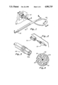
- FIG. 1 is a perspective representation of a nozzle, hand piece, cord and connector of the present invention.
- FIG. 2 is an enlarged exploded perspective view of the nozzle and the mating end of the hand piece illustrated in FIG. 1.
- FIG. 3 is a fragmentary enlarged perspective view of the connector end of the cord illustrated in FIG. 1.
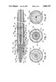
- FIG. 4 is an enlarged section view of the cord taken along line 4--4 of FIG. 1.
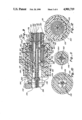
- FIG. 5 is an enlarged section view of the nozzle and front end of the hand piece taken along line 5--5 of FIG. 1 with parts removed to condense the size.
- FIG. 6 is an enlarged section view taken along line 6--6 of FIG. 5.
- FIG. 7 is an enlarged section view taken along line 7--7 of FIG. 5.
- FIG. 8 is an enlarged section view taken along line 8--8 of FIG. 5.
- FIG. 9 is an enlarged section view of the connector taken along line 9--9 of FIG. 1.
- FIG. 10 is a section view taken along line 10--10 of FIG. 9.
- FIG. 11 is a section view taken along line 11--11 of FIG. 9.
- FIG. 12 is a section view taken along line 12--12 of FIG. 9.
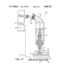
- FIG. 13 is a generalized schematic view of an electrosurgical unit (ESU) embodying the present invention, illustrating an electrosurgical generator (ESG), a gas delivery apparatus, a segment of tissue shown illustratively in cross-section, and the elements of the invention shown in FIG. 1.
- ESG electrosurgical generator
- ESU electrosurgical unit
- the ESU 40 includes three major components, a pencil 42 which is manipulated by the surgeon, gas delivery apparatus 44 and an electrosurgical generator (ESG) 46.
- a flexible cord 48 connects the gas delivery apparatus 44 and the ESG 46 to the pencil 42.
- the gas delivery apparatus 44 delivers a preselected gas through a plurality of individual hose passageways or lumens 50 in the cord 48 to the pencil 42.
- the gas issues from a nozzle 52 of the pencil 42 in a directed or substantially laminar flow stream or jet 54.
- the ESG 46 supplies electrical energy over a supply conductor 56 of the cord 48 to the pencil 42.
- the conductor 56 is electrically connected in the pencil to a needle-like electrode 58 which forms a part of the nozzle 52.
- the electrical energy supplied by the ESG 46 is of predetermined characteristic sufficient to ionize the gas flowing through the nozzle 52 and to create ionized pathways in the jet 54.
- the electrical energy travels in the ionized pathways in the jet 54 to a body tissue 62 where it creates a predetermined electrosurgical effect on the tissue 62.
- arcs 60 In the fulguration mode of operation of the ESU, electrical energy is transferred in the ionized pathways in the form of arcs 60.
- the arcs 60 travel within the jet 54 until they reach the tissue 62 at the electrical surgical site.
- the jet 54 expands slightly above the surface of the tissue 62 and the arcs 60 disburse over a slightly enlarged area of the tissue surface compared to the cross-section of the jet 54.
- Electrical energy of the arcs is transferred into the tissue 62 and creates the upper arc hole reticulum or layer 30 and a desiccated layer 32 therebelow.
- the arc hole reticulum 30 and the desiccated layer are schematically illustrated in FIG. 13.
- the ionized pathways in the jet 54 transfer electrical energy from the electrode 58 as a non-arcing, conductive current.
- a gentle coupling effect is created at the tissue which does not cause holes in the tissue, because arcs are not present.
- Ser. No. 849,950 a desiccative electrosurgical effect is created, and only a desiccation layer similar to that schematically shown at 32 in FIG. 13 is formed on the surface of the tissue.
- the normal unaffected tissue structure such as that at 34 exists below the surface desiccated layer 32.
- the jet expands slightly at the surface of the tissue to couple the nonarcing electrical current over a slightly enlarged area of the tissue surface compared to the cross-sectional size of the jet.
- This type of desiccative coagulation electrosurgical effect has heretofore not been obtainable in the field of electrosurgery except through the apparatus disclosed in the parent application hereto.
- the desiccative effects on the tissue offer the possibility of accomplishing substantially new and different types of electrosurgical procedures by use of an ESU.
- the pencil 42 includes a handle portion 76 and the nozzle 52 with the nozzle being threadedly connected to the handle for easy removal therefrom.
- the handle portion 76 of the pencil includes a generally cylindrical dielectric body 78 which may be ceramic.
- the cylindrical body 78 has a central axial passageway 80 therethrough which is relatively narrower at a leading end than at a trailing end as created by a relatively thick wall 82 at its leading end.
- the open leading end of the handle has internal threads 84 which form exemplary means for releasably and connecting receiving the nozzle 52 as will be described in more detail hereinafter.
- a socket insert 86 is disposed internally of the handle portion 76 at the forwardmost extent of the large diameter portion 80L of the passageway through the handle.
- the socket insert 86 is also of cylindrical configuration having an outer diameter substantially the same as the inner diameter of the handle 76 at the location where the insert is positioned within the handle.
- a disc-like wall 88 is formed having a plurality of circumferentially spaced openings 90 therethrough adapted to align with the passageways or lumens 50 through the hose 48.
- the wall 88 also has a central opening 92 therethrough adapted to accommodate the conductor 56 which passes through the hose and takes the form of a braided metal wire.
- a forwardly projecting internal cylindrical sleeve 94 projects forwardly from the disc-like wall 88 and confines and supports an electrical connector means such as a metallic socket 96 adapted to receive the electrode 58 of the nozzle as will be discussed later.
- the metallic socket 96 also includes a receptacle for receiving and retaining the leading end of the braided metal wire 56 which projects thereinto from the leading end of the hose 48.
- the covering 98 is of a soft pliable material such as silicone and also overlaps the leading end of the handle portion leaving the opening through the leading end of the handle portion unobstructed. It is important to note, however, that a portion of the covering does overlap the leading end of the handle forming a boot 100 which facilitates the establishment of a hermetic seal between the nozzle and the handle.
- the nozzle 52 includes inner and outer dielectric component parts 51 and 53 with the electrode 58 being supported axially within the inner part.
- the nozzle is adapted to be releasably connected to the handle 76 to define the pencil 42.
- the inner part 51 of the nozzle has a forwardly projecting cylindrical-body 102, an integral intermediate enlarged cylindrical body 104 at the trailing end of the forwardly projecting cylindrical body 102, and an integral trailing cylindrical body 106 protruding rearwardly from the intermediate body.
- the intermediate body 104 at its trailing end has a plurality of inwardly directed ribs 108 which support the trailing body 106.
- the ribs 108 define passageways 110 therebetween through which gas is enabled to pass from the hose 48 through the socket insert 86 in the handle portion and subsequently through the passageways 110 for exposure to the electrode 58 within a nozzle passageway or mixing chamber 112 defined by the cylindrical inner spaces of the forward and intermediate bodys 102 and 104 respectively of the inner part 51.
- the trailing body 106 of the inner part has a cylindrical passage 114 therethrough adapted to mate with and receive the electrode 58 which is made of a conductive metal material and secured in the trailing body 106 in any suitable manner.
- the electrode 58 protrudes rearwardly from the trailing body of the inner part 51 so as to be receivable in the metal socket provided in the socket insert 86 of the handle portion.
- the trailing body of the inner part supports the electrode 58 along a small or minority portion of its length, and as such and in conjunction with the ribs are one example of support means for supporting the electrode.
- the support for the electrode extends only along a relatively short length of the electrode, for example, less than 20% of its length, exposing a significant portion of the electrode to the mixing chamber 112 and thus the gases flowing therethrough to improve initiation of the ionization of the gas. It has been determined that the initiation of the ionization process is facilitated by a greater exposure of the electrode to the gas jet stream 54 and for this reason, this feature of the invention is of significant value.
- the outer part 53 of the nozzle 52 includes an enlarged frusto-conical head 116 and a trailing reduced diameter cylindrical portion 118 having external threads 120 adapted to mate with and be received in the internal threads 84 at the leading end of the handle portion.
- the outer part of the nozzle is affixed to and is unitary with the inner part 51 of the nozzle so that as the outer part is threaded into the leading end of the handle portion, the trailing end of the electrode 58 is inserted into the metallic socket in the handle portion in a positive manner.
- the frusto-conical head 116 has a trailing circular radially disposed surface 122 which abuts with the boot 100 or overlapping portion of the handle cover to positively establish a hermetic seal between the nozzle and the handle portion. This seal is of critical importance in preventing the escape of gas and the possible transmittal of electrical energy to the surgeon's hand.
- the opposite or trailing end of the hose 48 is connected to the gas delivery apparatus 44 and the ESG 46 through a connector 124.
- the connector is best illustrated in FIGS. 3 and 9-12 as including a female mating portion of member 126 which is directly fastenable to the gas delivery apparatus and ESG to receive gas and electrical energy therefrom and a male mating portion of member 128 secured in a unitary fashion to the trailing end of the hose.
- An intermediate sleeve member 130 is also provided which permits the hose to be positively secured to the female member 126 in a rotative relationship so that the hose will not form kinks as the pencil 42 is manipulated by a surgeon.
- the female member 126 includes an outer cylindrical opening 140 adapted to receive the trailing end of the hose 48 with the opening 140 having internal threads 142 formed therein.
- a rear wall 144 of the female member supports a forwardly projecting central cylindrical hub 146 which extends into the cylindrical opening 140 in the female member for approximately a third of its length.
- the cylindrical hub 146 has a cylindrical wall 148 and a plurality of radial inwardly directed ribs 150 defining therebetween a central axial passage 152 for receiving an a connecting electrode 154 on the trailing end of the hose.
- the metallic socket 136 in the gas delivery apparatus and ESG protrudes forwardly into the central axial passage 152 in a position to receive the electrode 154 in a manner to be described hereinafter.
- the forward edge of the cylindrical hub has a tapered surface 156 which is frusto-conical and rearwardly convergent and is continuous with the forward edges of the ribs at the locations where the ribs 150 are contiguous with the tapered surface 156.
- This frusto-conically tapered surface is adapted to cooperate with the trailing end of the hose in establishing a rotating hermetic seal as will become more clear later.
- the male member 128 of the connector 124 includes a body made of a moderately resilient material such as rubber and an internal supporting insert 158 that is received within the body.
- the body has an enlarged head 160 defined by two axially aligned frusto-conical surfaces 162 and 164 and a cylindrical extension portion 166 protruding forwardly away therefrom and adapted to receive the trailing end of the hose.
- the extension portion 166 has an internal cylindrical passageway 168 into which the hose 48 is inserted and retained in any suitable manner.
- the insert 158 is of generally cylindrical configuration having a protruding radial rib 170 around its trailing end which is adapted to be received within an annular recess 172 formed internally of the head 160.
- the insert has a plurality of openings 174 therethrough which are aligned with the passageways or lumens 50 through the hose so that gas can pass readily from the gas delivery apparatus 44 to the hose.
- the insert further includes an internal cylindrical sleeve 176 defining a cylindrical recess 178 in which the electrode 154 can be inserted and retained in any suitable manner.
- the electrode has a recess 180 defined in its leading end which is adapted to receive the end of the braided metal wire 56 that passes through the hose to establish an electrical connecting means and relationship between the braided metal wire and the electrode.
- the enlarged head 160 includes a solid interior wall 181 having circular openings 183 therethrough in alignment with the openings 174 through the insert 158.
- the wall 181 is integral with and supports a rearwardly projecting cylindrical sleeve 182 through a plurality of ribs 184 shown best in FIGS. 9 and 11.
- the sleeve 182 has an internal passageway 185 therethrough which receives the electrode 154 in a manner such that the electrode protrudes a short distance from the rearward end of the sleeve.
- the male and female members 128 and 126 respectively of the connector are dimensioned such that the rearwardmost frusto-conical surface 164 on the head 160, which defines a generally circular trailing edge 186 of the head and a rearwardly opening frusto-conical recess 187, engages the cylindrical hub 146 of the female member when the electrode 154 is positively seated in the metal socket 136.
- the circular opening 183 and the recess 187 form a center opening for passing gas into the hose 48.
- the cylindrical hub of the female member engages the frusto-conical surface 164 at a circular edge or annular manner so as to establish a hermetic seal therewith and to allow the male member to rotate relative to the female member while maintaining that seal.
- the male member 128 is positively retained in the female member 126 by the intermediate sleeve 130 which is of generally cylindrical configuration having a larger diameter trailing end 188 and a smaller diameter leading end 190.
- the smaller diameter leading end 190 is rotably disposed about the cylindrical extension portion 166 of the male element and defines a radial abutment shoulder 192 against which is disposed a washer member 194 preferably made of a fluoroplastic or other low friction material.
- the washer 194 fills a space between the radial abutment shoulder 192 on the intermediate sleeve and a radial shoulder 196 at the leading end of the enlarged head 160 of the male element so as to provide a low friction bearing surface between the intermediate sleeve and the male member.
- the large cylindrical end 188 of the intermediate sleeve has external threads 198 formed therein adapted to be received in the internal threads 142 of the female member and the portion of the sleeve rearwardly of the threads projects forwardly into a cylindrical socket 200 defined within the female member.
- the trailing end of the sleeve is adapted to abut the rear wall 144 of the female member when the sleeve 130 is fully threaded thereinto and at this same relative positioning of the intermediate sleeve with the female member, it will be appreciated that the male member is positively positioned relative to the female member as illustrated in FIG. 9 to establish the rotating seal between the male member and the female member along the frusto-conical surfaces 164 and 156.
- the electrode 154 is positively positioned in the socket 136 of the gas delivery and ESG apparatus such that electricity is dependably transferred along the rear electrode 154 and the braided metal wire to the electrode 58 in the nozzle 52 as desired. Further, a clear passageway is established for the gas which emanates from the gas delivery apparatus and passes first through the female connector member and subsequently the male connector member and the hose for delivery to the nozzle.
- the electrosurgical unit 40 herein described is used in accordance with the technique fully described in the aforenoted parent application which has been incorporated herein by reference and accordingly a description of that technique is not repeated.
Abstract
Description
Claims (14)
Priority Applications (9)
| Application Number | Priority Date | Filing Date | Title |
|---|---|---|---|
| US07/224,485 US4901719A (en) | 1986-04-08 | 1988-07-26 | Electrosurgical conductive gas stream equipment |
| CA000596013A CA1323664C (en) | 1988-07-26 | 1989-04-07 | Electrosurigical conductive gas stream equipment |
| EP89630122A EP0353177B1 (en) | 1988-07-26 | 1989-07-25 | Electrosurgical conductive gas stream equipment |
| DE89630122T DE68912842T2 (en) | 1988-07-26 | 1989-07-25 | Electrosurgical device that conducts gas flow. |
| ES89630122T ES2049347T3 (en) | 1988-07-26 | 1989-07-25 | CONDUCTOR GAS FLOW ELECTRO-SURGICAL EQUIPMENT. |
| NZ230097A NZ230097A (en) | 1988-07-26 | 1989-07-26 | Electrosurgical conductive gas stream equipment |
| AU38994/89A AU626565B2 (en) | 1988-07-26 | 1989-07-26 | Electrosurgical conductive gas stream equipment |
| NZ24318789A NZ243187A (en) | 1988-07-26 | 1989-07-26 | Electrosurgical unit for delivery of gas and electrical energy to tissue |
| US07/838,375 USRE34780E (en) | 1986-04-08 | 1992-02-19 | Electrosurgical conductive gas stream equipment |
Applications Claiming Priority (2)
| Application Number | Priority Date | Filing Date | Title |
|---|---|---|---|
| US06/849,950 US4781175A (en) | 1986-04-08 | 1986-04-08 | Electrosurgical conductive gas stream technique of achieving improved eschar for coagulation |
| US07/224,485 US4901719A (en) | 1986-04-08 | 1988-07-26 | Electrosurgical conductive gas stream equipment |
Related Parent Applications (1)
| Application Number | Title | Priority Date | Filing Date |
|---|---|---|---|
| US06/849,950 Continuation-In-Part US4781175A (en) | 1986-04-08 | 1986-04-08 | Electrosurgical conductive gas stream technique of achieving improved eschar for coagulation |
Related Child Applications (1)
| Application Number | Title | Priority Date | Filing Date |
|---|---|---|---|
| US07/838,375 Reissue USRE34780E (en) | 1986-04-08 | 1992-02-19 | Electrosurgical conductive gas stream equipment |
Publications (1)
| Publication Number | Publication Date |
|---|---|
| US4901719A true US4901719A (en) | 1990-02-20 |
Family
ID=22840911
Family Applications (2)
| Application Number | Title | Priority Date | Filing Date |
|---|---|---|---|
| US07/224,485 Ceased US4901719A (en) | 1986-04-08 | 1988-07-26 | Electrosurgical conductive gas stream equipment |
| US07/838,375 Expired - Lifetime USRE34780E (en) | 1986-04-08 | 1992-02-19 | Electrosurgical conductive gas stream equipment |
Family Applications After (1)
| Application Number | Title | Priority Date | Filing Date |
|---|---|---|---|
| US07/838,375 Expired - Lifetime USRE34780E (en) | 1986-04-08 | 1992-02-19 | Electrosurgical conductive gas stream equipment |
Country Status (7)
| Country | Link |
|---|---|
| US (2) | US4901719A (en) |
| EP (1) | EP0353177B1 (en) |
| AU (1) | AU626565B2 (en) |
| CA (1) | CA1323664C (en) |
| DE (1) | DE68912842T2 (en) |
| ES (1) | ES2049347T3 (en) |
| NZ (1) | NZ230097A (en) |
Cited By (123)
| Publication number | Priority date | Publication date | Assignee | Title |
|---|---|---|---|---|
| WO1991013593A1 (en) * | 1990-03-16 | 1991-09-19 | Beacon Laboratories, Inc. | Dual mode electrosurgical pencil |
| US5088997A (en) * | 1990-03-15 | 1992-02-18 | Valleylab, Inc. | Gas coagulation device |
| WO1992005743A1 (en) * | 1990-10-04 | 1992-04-16 | Birtcher Medical Systems, Inc. | Electrosurgical handpiece incorporating blade and gas functionality |
| WO1993001758A1 (en) * | 1991-07-15 | 1993-02-04 | Jerome Canady | Surgical coagulation device |
| WO1993007821A1 (en) * | 1991-10-18 | 1993-04-29 | Birtcher Medical Systems, Inc. | Multifunctional probe for minimally invasive surgery |
| US5217457A (en) * | 1990-03-15 | 1993-06-08 | Valleylab Inc. | Enhanced electrosurgical apparatus |
| US5306238A (en) * | 1990-03-16 | 1994-04-26 | Beacon Laboratories, Inc. | Laparoscopic electrosurgical pencil |
| US5320621A (en) * | 1993-05-05 | 1994-06-14 | Birtcher Medial Systems, Inc. | Technique for incorporating an electrode within a nozzle |
| US5484435A (en) * | 1992-01-15 | 1996-01-16 | Conmed Corporation | Bipolar electrosurgical instrument for use in minimally invasive internal surgical procedures |
| US5626560A (en) * | 1993-04-13 | 1997-05-06 | Soring Medizintechnik Gmbh | Diathermic hand-held instrument with an endoscopic probe |
| US5669904A (en) * | 1995-03-07 | 1997-09-23 | Valleylab Inc. | Surgical gas plasma ignition apparatus and method |
| US5669907A (en) * | 1995-02-10 | 1997-09-23 | Valleylab Inc. | Plasma enhanced bipolar electrosurgical system |
| US5669934A (en) * | 1991-02-13 | 1997-09-23 | Fusion Medical Technologies, Inc. | Methods for joining tissue by applying radiofrequency energy to performed collagen films and sheets |
| US5720745A (en) * | 1992-11-24 | 1998-02-24 | Erbe Electromedizin Gmbh | Electrosurgical unit and method for achieving coagulation of biological tissue |
| US5749895A (en) * | 1991-02-13 | 1998-05-12 | Fusion Medical Technologies, Inc. | Method for bonding or fusion of biological tissue and material |
| US5766171A (en) * | 1994-02-09 | 1998-06-16 | Keravision, Inc. | Electrosurgical procedure for the treatment of the cornea |
| WO1999015091A1 (en) | 1997-09-22 | 1999-04-01 | Sherwood Services Ag | Surgical gas plasma ignition apparatus and method |
| US6013075A (en) * | 1994-12-30 | 2000-01-11 | Technova Incorporated | Medical coagulation apparatus |
| US6039736A (en) * | 1998-09-29 | 2000-03-21 | Sherwood Services Ag | Side-Fire coagulator |
| EP1127551A1 (en) * | 2000-02-16 | 2001-08-29 | Sherwood Services AG | Inert gas enhanced electrosurgical apparatus |
| EP1264580A1 (en) * | 2001-06-05 | 2002-12-11 | Electrosurgery Associates, LLC | Instant ignition electrosurgical probe and method for electrosurgical cutting and ablation |
| US20030065324A1 (en) * | 1998-09-29 | 2003-04-03 | Platt Robert C. | Swirling system for ionizable gas coagulator |
| US20030093073A1 (en) * | 1999-10-05 | 2003-05-15 | Platt Robert C. | Articulating ionizable gas coagulator |
| US20030105458A1 (en) * | 1999-10-05 | 2003-06-05 | Platt Robert C. | Multi-port side-fire coagulator |
| US20040044342A1 (en) * | 2002-09-03 | 2004-03-04 | Mackay Dale Victor | Electrosurgical apparatus |
| US6747218B2 (en) | 2002-09-20 | 2004-06-08 | Sherwood Services Ag | Electrosurgical haptic switch including snap dome and printed circuit stepped contact array |
| US20040153055A1 (en) * | 2000-12-15 | 2004-08-05 | Tyco Healthcare Group Lp | Electrosurgical electrode shroud |
| US20040186470A1 (en) * | 2000-02-22 | 2004-09-23 | Gyrus Medical Limited | Tissue resurfacing |
| US20040230262A1 (en) * | 2003-02-20 | 2004-11-18 | Sartor Joe D. | Motion detector for controlling electrosurgical output |
| WO2005028012A1 (en) * | 2003-09-19 | 2005-03-31 | Fisher & Paykel Healthcare Limtied | A connector |
| US20050103210A1 (en) * | 2002-03-01 | 2005-05-19 | Peter King | Product coating method and apparatus |
| US20050107782A1 (en) * | 2003-11-19 | 2005-05-19 | Reschke Arlan J. | Pistol grip electrosurgical pencil with manual aspirator/irrigator and methods of using the same |
| US20050113823A1 (en) * | 2003-11-20 | 2005-05-26 | Reschke Arlan J. | Electrosurgical pencil with improved controls |
| US20050113824A1 (en) * | 2003-11-20 | 2005-05-26 | Sartor Joe D. | Electrosurgical pencil with improved controls |
| US20050149012A1 (en) * | 2000-02-22 | 2005-07-07 | Gyrus Medical Limited | Tissue resurfacing |
| US20050171528A1 (en) * | 2004-02-03 | 2005-08-04 | Sartor Joe D. | Self contained, gas-enhanced surgical instrument |
| US20050192643A1 (en) * | 2004-02-27 | 2005-09-01 | Gonnering Wayne J. | Gas-assisted electrosurgical accessory connector and method with improved gas sealing and biasing for maintaining a gas tight seal |
| US20060052772A1 (en) * | 2004-02-03 | 2006-03-09 | Sartor Joe D | Gas-enhanced surgical instrument |
| US20060058783A1 (en) * | 2002-07-25 | 2006-03-16 | Sherwood Services Ag | Electrosurgical pencil with drag sensing capability |
| US20060116674A1 (en) * | 2000-02-22 | 2006-06-01 | Rhytec Limited | Method of regenerating the recticular architecture of the dermis |
| US20060122595A1 (en) * | 2002-09-04 | 2006-06-08 | Guenter Farin | Applicatior for an electrosurgical instrument |
| US20060189973A1 (en) * | 2004-04-29 | 2006-08-24 | Van Der Weide Daniel W | Segmented catheter for tissue ablation |
| US20060189976A1 (en) * | 2005-01-18 | 2006-08-24 | Alma Lasers International | System and method for treating biological tissue with a plasma gas discharge |
| US20060200122A1 (en) * | 2004-02-03 | 2006-09-07 | Sherwood Services Ag | Portable argon system |
| US20060235378A1 (en) * | 2005-04-18 | 2006-10-19 | Sherwood Services Ag | Slider control for ablation handset |
| US20060276780A1 (en) * | 2004-04-29 | 2006-12-07 | Brace Christopher L | Air-core microwave ablation antennas |
| US20060292271A1 (en) * | 2005-06-27 | 2006-12-28 | Peter King | Spray coating method and apparatus |
| US20070016180A1 (en) * | 2004-04-29 | 2007-01-18 | Lee Fred T Jr | Microwave surgical device |
| US20070016181A1 (en) * | 2004-04-29 | 2007-01-18 | Van Der Weide Daniel W | Microwave tissue resection tool |
| US20070027446A1 (en) * | 2000-02-22 | 2007-02-01 | Rhytec Limited | Method of removing a tattoo |
| US20070049918A1 (en) * | 2005-08-24 | 2007-03-01 | Van Der Weide Daniel W | Microwave device for vascular ablation |
| US20070049914A1 (en) * | 2005-09-01 | 2007-03-01 | Sherwood Services Ag | Return electrode pad with conductive element grid and method |
| US20070049926A1 (en) * | 2005-08-25 | 2007-03-01 | Sartor Joe D | Handheld electrosurgical apparatus for controlling operating room equipment |
| US20070073287A1 (en) * | 2000-02-22 | 2007-03-29 | Rhytec Limited | Method of remodelling stretch marks |
| US20070093868A1 (en) * | 2005-10-20 | 2007-04-26 | Fugo Richard J | Plasma incising device including disposable incising tips for performing surgical procedures |
| US7244257B2 (en) | 2002-11-05 | 2007-07-17 | Sherwood Services Ag | Electrosurgical pencil having a single button variable control |
| US20070208337A1 (en) * | 2006-03-03 | 2007-09-06 | Sherwood Services Ag | Manifold for gas enhanced surgical instruments |
| US20070213709A1 (en) * | 2006-03-08 | 2007-09-13 | Sherwood Services Ag | Tissue coagulation method and device using inert gas |
| US20070260240A1 (en) * | 2006-05-05 | 2007-11-08 | Sherwood Services Ag | Soft tissue RF transection and resection device |
| US20070282319A1 (en) * | 2006-03-24 | 2007-12-06 | Micrablate, Inc. | Center fed dipole for use with tissue ablation systems, devices and methods |
| US20080004617A1 (en) * | 2004-07-15 | 2008-01-03 | Erbe Elektromedizin Gmbh | Adapter Device |
| US20080033424A1 (en) * | 2006-03-24 | 2008-02-07 | Micrablate | Transmission line with heat transfer ability |
| US20080039834A1 (en) * | 2005-02-11 | 2008-02-14 | Mackay Dale V | Electrosurgical probe |
| US20080045938A1 (en) * | 2006-07-14 | 2008-02-21 | Micrablate | Energy delivery systems and uses thereof |
| US20090054890A1 (en) * | 2007-08-23 | 2009-02-26 | Decarlo Arnold V | Electrosurgical device with LED adapter |
| US7500974B2 (en) | 2005-06-28 | 2009-03-10 | Covidien Ag | Electrode with rotatably deployable sheath |
| US7503917B2 (en) | 2003-11-20 | 2009-03-17 | Covidien Ag | Electrosurgical pencil with improved controls |
| US20090076505A1 (en) * | 2007-09-13 | 2009-03-19 | Arts Gene H | Electrosurgical instrument |
| US20090149851A1 (en) * | 2007-12-05 | 2009-06-11 | Tyco Healthcare Group Lp | Thermal Penetration and Arc Length Controllable Electrosurgical Pencil |
| GB2458329A (en) * | 2008-03-15 | 2009-09-16 | Microoncology Ltd | Applicator for plasma sterilisation of body cavities |
| US20090248018A1 (en) * | 2008-03-31 | 2009-10-01 | Tyco Healthcare Group Lp | Electrosurgical Pencil Including Improved Controls |
| US20090248016A1 (en) * | 2008-03-31 | 2009-10-01 | Heard David N | Electrosurgical Pencil Including Improved Controls |
| US20090248017A1 (en) * | 2008-03-31 | 2009-10-01 | Tyco Healthcare Group Lp | Electrosurgical Pencil Including Improved Controls |
| US20090326528A1 (en) * | 2005-01-18 | 2009-12-31 | Alma Lasers Ltd. | System and method for heating biological tissue via rf energy |
| US20100042094A1 (en) * | 2008-08-14 | 2010-02-18 | Arts Gene H | Surgical Gas Plasma Ignition Apparatus and Method |
| US20100042088A1 (en) * | 2008-08-14 | 2010-02-18 | Arts Gene H | Surgical Gas Plasma Ignition Apparatus and Method |
| US20100087815A1 (en) * | 2001-08-15 | 2010-04-08 | Nuortho Surgical Inc. | Electrosurgical Plenum |
| US20100204696A1 (en) * | 2009-02-10 | 2010-08-12 | Tyco Healthcare Group Lp | Extension Cutting Blade |
| US7785322B2 (en) | 2000-02-22 | 2010-08-31 | Plasmogen Inc. | Tissue treatment system |
| US20100243619A1 (en) * | 2009-03-27 | 2010-09-30 | Hypertherm, Inc. | Plasma arc torch rotational assembly |
| US7833222B2 (en) | 2004-02-03 | 2010-11-16 | Covidien Ag | Gas-enhanced surgical instrument with pressure safety feature |
| US7879033B2 (en) | 2003-11-20 | 2011-02-01 | Covidien Ag | Electrosurgical pencil with advanced ES controls |
| US20110071517A1 (en) * | 2009-09-23 | 2011-03-24 | Bovie Medical Corporation | Electrosurgical system to generate a pulsed plasma stream and method thereof |
| US20110087308A1 (en) * | 2001-08-15 | 2011-04-14 | Nuortho Surgical Inc. | Interfacing Media Manipulation with Non-Ablation Radiofrequency Energy System and Method |
| US20110121735A1 (en) * | 2000-02-22 | 2011-05-26 | Kreos Capital Iii (Uk) Limited | Tissue resurfacing |
| US20110139751A1 (en) * | 2008-05-30 | 2011-06-16 | Colorado State Univeristy Research Foundation | Plasma-based chemical source device and method of use thereof |
| US20110140607A1 (en) * | 2008-05-30 | 2011-06-16 | Colorado State University Research Foundation | System, method and apparatus for generating plasma |
| US8123744B2 (en) | 2006-08-29 | 2012-02-28 | Covidien Ag | Wound mediating device |
| US20120067212A1 (en) * | 2009-07-23 | 2012-03-22 | Neil Warren | Reduction And Removal Of Particles |
| US8162937B2 (en) | 2008-06-27 | 2012-04-24 | Tyco Healthcare Group Lp | High volume fluid seal for electrosurgical handpiece |
| US8222822B2 (en) | 2009-10-27 | 2012-07-17 | Tyco Healthcare Group Lp | Inductively-coupled plasma device |
| US8226643B2 (en) | 2004-02-03 | 2012-07-24 | Covidien Ag | Gas-enhanced surgical instrument with pressure safety feature |
| US20120207888A1 (en) * | 2011-02-09 | 2012-08-16 | Spice Application Systems Limited | Comestible Coating Delivery Method and Apparatus |
| US8409190B2 (en) | 2002-12-17 | 2013-04-02 | Bovie Medical Corporation | Electrosurgical device to generate a plasma stream |
| US20130261536A1 (en) * | 2012-03-27 | 2013-10-03 | Tyco Healthcare Group Lp | System and Method for Cholecystectomy |
| US8623012B2 (en) | 2001-08-15 | 2014-01-07 | Nuortho Surgical, Inc. | Electrosurgical plenum |
| CN104083206A (en) * | 2014-07-28 | 2014-10-08 | 重庆金山科技(集团)有限公司 | Argon spray pipe structure |
| US20150013999A1 (en) * | 2013-07-11 | 2015-01-15 | Scott & White Healthcare | Device, System and Method for Fire Prevention in an Operating Room |
| US8994270B2 (en) | 2008-05-30 | 2015-03-31 | Colorado State University Research Foundation | System and methods for plasma application |
| US9028656B2 (en) | 2008-05-30 | 2015-05-12 | Colorado State University Research Foundation | Liquid-gas interface plasma device |
| US9119649B2 (en) | 2009-07-28 | 2015-09-01 | Neuwave Medical, Inc. | Energy delivery systems and uses thereof |
| US20150305795A1 (en) * | 2012-10-04 | 2015-10-29 | Gyrus Medical Limited | Electrosurgical plasma apparatus and system |
| US9192438B2 (en) | 2011-12-21 | 2015-11-24 | Neuwave Medical, Inc. | Energy delivery systems and uses thereof |
| US9272359B2 (en) | 2008-05-30 | 2016-03-01 | Colorado State University Research Foundation | Liquid-gas interface plasma device |
| US9387269B2 (en) | 2011-01-28 | 2016-07-12 | Bovie Medical Corporation | Cold plasma jet hand sanitizer |
| US9408658B2 (en) | 2011-02-24 | 2016-08-09 | Nuortho Surgical, Inc. | System and method for a physiochemical scalpel to eliminate biologic tissue over-resection and induce tissue healing |
| US9532827B2 (en) | 2009-06-17 | 2017-01-03 | Nuortho Surgical Inc. | Connection of a bipolar electrosurgical hand piece to a monopolar output of an electrosurgical generator |
| US9532826B2 (en) | 2013-03-06 | 2017-01-03 | Covidien Lp | System and method for sinus surgery |
| US9555145B2 (en) | 2013-03-13 | 2017-01-31 | Covidien Lp | System and method for biofilm remediation |
| US9579142B1 (en) | 2012-12-13 | 2017-02-28 | Nuortho Surgical Inc. | Multi-function RF-probe with dual electrode positioning |
| US9681907B2 (en) | 2010-01-28 | 2017-06-20 | Bovie Medical Corporation | Electrosurgical apparatus to generate a dual plasma stream and method thereof |
| US9861440B2 (en) | 2010-05-03 | 2018-01-09 | Neuwave Medical, Inc. | Energy delivery systems and uses thereof |
| US9888954B2 (en) | 2012-08-10 | 2018-02-13 | Cook Medical Technologies Llc | Plasma resection electrode |
| US10188447B2 (en) | 2014-04-02 | 2019-01-29 | Gyrus Medical Limited | Electrosurgical system |
| US10376314B2 (en) | 2006-07-14 | 2019-08-13 | Neuwave Medical, Inc. | Energy delivery systems and uses thereof |
| US10531917B2 (en) | 2016-04-15 | 2020-01-14 | Neuwave Medical, Inc. | Systems and methods for energy delivery |
| US10716587B2 (en) | 2014-06-13 | 2020-07-21 | Surgis Medical Llc | Surgical device with light |
| US10918433B2 (en) | 2016-09-27 | 2021-02-16 | Apyx Medical Corporation | Devices, systems and methods for enhancing physiological effectiveness of medical cold plasma discharges |
| US10952792B2 (en) | 2015-10-26 | 2021-03-23 | Neuwave Medical, Inc. | Energy delivery systems and uses thereof |
| US11129665B2 (en) | 2015-12-02 | 2021-09-28 | Apyx Medical Corporation | Mixing cold plasma beam jets with atmopshere |
| US11564732B2 (en) | 2019-12-05 | 2023-01-31 | Covidien Lp | Tensioning mechanism for bipolar pencil |
| US11672596B2 (en) | 2018-02-26 | 2023-06-13 | Neuwave Medical, Inc. | Energy delivery devices with flexible and adjustable tips |
| US11832879B2 (en) | 2019-03-08 | 2023-12-05 | Neuwave Medical, Inc. | Systems and methods for energy delivery |
Families Citing this family (25)
| Publication number | Priority date | Publication date | Assignee | Title |
|---|---|---|---|---|
| DE9104559U1 (en) * | 1991-04-15 | 1992-08-13 | Soering Gmbh Medizintechnik, 2085 Quickborn, De | |
| DE19516238A1 (en) | 1995-05-03 | 1996-11-07 | Delma Elektro Med App | Method and device for generating an arc in biological tissue using high-frequency surgical means |
| US7498509B2 (en) * | 1995-09-28 | 2009-03-03 | Fiberspar Corporation | Composite coiled tubing end connector |
| US8678042B2 (en) | 1995-09-28 | 2014-03-25 | Fiberspar Corporation | Composite spoolable tube |
| US5921285A (en) | 1995-09-28 | 1999-07-13 | Fiberspar Spoolable Products, Inc. | Composite spoolable tube |
| DE19626976C2 (en) * | 1996-04-25 | 1998-05-14 | Erbe Elektromedizin | Surgical instrument |
| US6206878B1 (en) | 1999-05-07 | 2001-03-27 | Aspen Laboratories, Inc. | Condition responsive gas flow adjustment in gas-assisted electrosurgery |
| GB2413166B (en) | 2001-04-27 | 2005-11-30 | Fiberspar Corp | Improved composite tubing |
| US6679880B2 (en) * | 2001-07-23 | 2004-01-20 | Par Value International Limited | Electrosurgical hand piece |
| US20090054893A1 (en) * | 2004-02-03 | 2009-02-26 | Sartor Joe D | Gas-enhanced surgical instrument with pressure safety feature |
| CA2490176C (en) | 2004-02-27 | 2013-02-05 | Fiberspar Corporation | Fiber reinforced spoolable pipe |
| US7271363B2 (en) * | 2004-09-01 | 2007-09-18 | Noritsu Koki Co., Ltd. | Portable microwave plasma systems including a supply line for gas and microwaves |
| US8187687B2 (en) | 2006-03-21 | 2012-05-29 | Fiberspar Corporation | Reinforcing matrix for spoolable pipe |
| US8839822B2 (en) | 2006-03-22 | 2014-09-23 | National Oilwell Varco, L.P. | Dual containment systems, methods and kits |
| US9554843B2 (en) * | 2006-09-01 | 2017-01-31 | Conmed Corporation | Adapter and method for converting gas-enhanced electrosurgical coagulation instrument for cutting |
| US8671992B2 (en) | 2007-02-02 | 2014-03-18 | Fiberspar Corporation | Multi-cell spoolable composite pipe |
| US8746289B2 (en) * | 2007-02-15 | 2014-06-10 | Fiberspar Corporation | Weighted spoolable pipe |
| US8057470B2 (en) * | 2007-08-30 | 2011-11-15 | Conmed Corporation | Integrated smoke evacuation electrosurgical pencil and method |
| CA2641492C (en) | 2007-10-23 | 2016-07-05 | Fiberspar Corporation | Heated pipe and methods of transporting viscous fluid |
| CA2690926C (en) | 2009-01-23 | 2018-03-06 | Fiberspar Corporation | Downhole fluid separation |
| CA2783764C (en) | 2009-12-15 | 2017-08-15 | Fiberspar Corporation | System and methods for removing fluids from a subterranean well |
| US8955599B2 (en) | 2009-12-15 | 2015-02-17 | Fiberspar Corporation | System and methods for removing fluids from a subterranean well |
| WO2014026190A1 (en) | 2012-08-10 | 2014-02-13 | National Oilwell Varco, L.P. | Composite coiled tubing connectors |
| EP3984480A1 (en) | 2020-10-16 | 2022-04-20 | Erbe Elektromedizin GmbH | Multi-lumen probe |
| EP4209188A1 (en) * | 2022-01-07 | 2023-07-12 | Erbe Elektromedizin GmbH | Plasma probe |
Citations (6)
| Publication number | Priority date | Publication date | Assignee | Title |
|---|---|---|---|---|
| US2376265A (en) * | 1943-02-25 | 1945-05-15 | Northrop Aircraft Inc | Inert gas blanketed arc welding torch |
| US2828747A (en) * | 1952-12-06 | 1958-04-01 | Birtcher Corp | Gas-blanketed electro-surgical device |
| US3158730A (en) * | 1962-11-08 | 1964-11-24 | Union Carbide Corp | Gas shielded arc torch |
| US3690567A (en) * | 1970-03-09 | 1972-09-12 | Lawrence A Borneman | Electric arc welding gun having a nozzle with a removable metal liner to protect the nozzle from weld splatter |
| US4682005A (en) * | 1985-02-22 | 1987-07-21 | Lair Liquide, Societe Anonyme Pour L'etude Et L'exploitation Des Procedes Georges Claude | Plasma welding or cutting torch provided with a nozzle cartridge |
| US4781175A (en) * | 1986-04-08 | 1988-11-01 | C. R. Bard, Inc. | Electrosurgical conductive gas stream technique of achieving improved eschar for coagulation |
Family Cites Families (7)
| Publication number | Priority date | Publication date | Assignee | Title |
|---|---|---|---|---|
| DE1159574B (en) * | 1961-11-29 | 1963-12-19 | Siemens Reiniger Werke Ag | Safety device for high-frequency surgical apparatus |
| US4057064A (en) * | 1976-01-16 | 1977-11-08 | Valleylab, Inc. | Electrosurgical method and apparatus for initiating an electrical discharge in an inert gas flow |
| US4060088A (en) * | 1976-01-16 | 1977-11-29 | Valleylab, Inc. | Electrosurgical method and apparatus for establishing an electrical discharge in an inert gas flow |
| US4040426A (en) * | 1976-01-16 | 1977-08-09 | Valleylab, Inc. | Electrosurgical method and apparatus for initiating an electrical discharge in an inert gas flow |
| FR2474857B1 (en) * | 1980-02-06 | 1986-12-12 | Boutmy Ets | PLURIFUNCTIONAL SURGICAL APPARATUS |
| US4562838A (en) * | 1981-01-23 | 1986-01-07 | Walker William S | Electrosurgery instrument |
| US4711238A (en) * | 1985-03-14 | 1987-12-08 | Cunningham Frank W | Meniscal cutting device |
-
1988
- 1988-07-26 US US07/224,485 patent/US4901719A/en not_active Ceased
-
1989
- 1989-04-07 CA CA000596013A patent/CA1323664C/en not_active Expired - Lifetime
- 1989-07-25 ES ES89630122T patent/ES2049347T3/en not_active Expired - Lifetime
- 1989-07-25 DE DE89630122T patent/DE68912842T2/en not_active Expired - Lifetime
- 1989-07-25 EP EP89630122A patent/EP0353177B1/en not_active Expired - Lifetime
- 1989-07-26 NZ NZ230097A patent/NZ230097A/en unknown
- 1989-07-26 AU AU38994/89A patent/AU626565B2/en not_active Expired
-
1992
- 1992-02-19 US US07/838,375 patent/USRE34780E/en not_active Expired - Lifetime
Patent Citations (6)
| Publication number | Priority date | Publication date | Assignee | Title |
|---|---|---|---|---|
| US2376265A (en) * | 1943-02-25 | 1945-05-15 | Northrop Aircraft Inc | Inert gas blanketed arc welding torch |
| US2828747A (en) * | 1952-12-06 | 1958-04-01 | Birtcher Corp | Gas-blanketed electro-surgical device |
| US3158730A (en) * | 1962-11-08 | 1964-11-24 | Union Carbide Corp | Gas shielded arc torch |
| US3690567A (en) * | 1970-03-09 | 1972-09-12 | Lawrence A Borneman | Electric arc welding gun having a nozzle with a removable metal liner to protect the nozzle from weld splatter |
| US4682005A (en) * | 1985-02-22 | 1987-07-21 | Lair Liquide, Societe Anonyme Pour L'etude Et L'exploitation Des Procedes Georges Claude | Plasma welding or cutting torch provided with a nozzle cartridge |
| US4781175A (en) * | 1986-04-08 | 1988-11-01 | C. R. Bard, Inc. | Electrosurgical conductive gas stream technique of achieving improved eschar for coagulation |
Cited By (250)
| Publication number | Priority date | Publication date | Assignee | Title |
|---|---|---|---|---|
| US5217457A (en) * | 1990-03-15 | 1993-06-08 | Valleylab Inc. | Enhanced electrosurgical apparatus |
| US5088997A (en) * | 1990-03-15 | 1992-02-18 | Valleylab, Inc. | Gas coagulation device |
| US5098430A (en) * | 1990-03-16 | 1992-03-24 | Beacon Laboratories, Inc. | Dual mode electrosurgical pencil |
| WO1991013593A1 (en) * | 1990-03-16 | 1991-09-19 | Beacon Laboratories, Inc. | Dual mode electrosurgical pencil |
| US5306238A (en) * | 1990-03-16 | 1994-04-26 | Beacon Laboratories, Inc. | Laparoscopic electrosurgical pencil |
| WO1992005743A1 (en) * | 1990-10-04 | 1992-04-16 | Birtcher Medical Systems, Inc. | Electrosurgical handpiece incorporating blade and gas functionality |
| US5256138A (en) * | 1990-10-04 | 1993-10-26 | The Birtcher Corporation | Electrosurgical handpiece incorporating blade and conductive gas functionality |
| US5749895A (en) * | 1991-02-13 | 1998-05-12 | Fusion Medical Technologies, Inc. | Method for bonding or fusion of biological tissue and material |
| US5669934A (en) * | 1991-02-13 | 1997-09-23 | Fusion Medical Technologies, Inc. | Methods for joining tissue by applying radiofrequency energy to performed collagen films and sheets |
| US5207675A (en) * | 1991-07-15 | 1993-05-04 | Jerome Canady | Surgical coagulation device |
| WO1993001758A1 (en) * | 1991-07-15 | 1993-02-04 | Jerome Canady | Surgical coagulation device |
| WO1993007821A1 (en) * | 1991-10-18 | 1993-04-29 | Birtcher Medical Systems, Inc. | Multifunctional probe for minimally invasive surgery |
| US5449356A (en) * | 1991-10-18 | 1995-09-12 | Birtcher Medical Systems, Inc. | Multifunctional probe for minimally invasive surgery |
| US5484435A (en) * | 1992-01-15 | 1996-01-16 | Conmed Corporation | Bipolar electrosurgical instrument for use in minimally invasive internal surgical procedures |
| US5720745A (en) * | 1992-11-24 | 1998-02-24 | Erbe Electromedizin Gmbh | Electrosurgical unit and method for achieving coagulation of biological tissue |
| US5626560A (en) * | 1993-04-13 | 1997-05-06 | Soring Medizintechnik Gmbh | Diathermic hand-held instrument with an endoscopic probe |
| US5320621A (en) * | 1993-05-05 | 1994-06-14 | Birtcher Medial Systems, Inc. | Technique for incorporating an electrode within a nozzle |
| US5766171A (en) * | 1994-02-09 | 1998-06-16 | Keravision, Inc. | Electrosurgical procedure for the treatment of the cornea |
| US6013075A (en) * | 1994-12-30 | 2000-01-11 | Technova Incorporated | Medical coagulation apparatus |
| US5669907A (en) * | 1995-02-10 | 1997-09-23 | Valleylab Inc. | Plasma enhanced bipolar electrosurgical system |
| US5669904A (en) * | 1995-03-07 | 1997-09-23 | Valleylab Inc. | Surgical gas plasma ignition apparatus and method |
| US6213999B1 (en) | 1995-03-07 | 2001-04-10 | Sherwood Services Ag | Surgical gas plasma ignition apparatus and method |
| WO1999015091A1 (en) | 1997-09-22 | 1999-04-01 | Sherwood Services Ag | Surgical gas plasma ignition apparatus and method |
| US6039736A (en) * | 1998-09-29 | 2000-03-21 | Sherwood Services Ag | Side-Fire coagulator |
| US20030065324A1 (en) * | 1998-09-29 | 2003-04-03 | Platt Robert C. | Swirling system for ionizable gas coagulator |
| US6666865B2 (en) | 1998-09-29 | 2003-12-23 | Sherwood Services Ag | Swirling system for ionizable gas coagulator |
| US20030105458A1 (en) * | 1999-10-05 | 2003-06-05 | Platt Robert C. | Multi-port side-fire coagulator |
| US7955330B2 (en) | 1999-10-05 | 2011-06-07 | Covidien Ag | Multi-port side-fire coagulator |
| US7927330B2 (en) | 1999-10-05 | 2011-04-19 | Covidien Ag | Multi-port side-fire coagulator |
| US20030093073A1 (en) * | 1999-10-05 | 2003-05-15 | Platt Robert C. | Articulating ionizable gas coagulator |
| US8251995B2 (en) | 1999-10-05 | 2012-08-28 | Covidien Ag | Articulating ionizable gas coagulator |
| US20050015086A1 (en) * | 1999-10-05 | 2005-01-20 | Platt Robert C. | Multi-port side-fire coagulator |
| US20100016856A1 (en) * | 1999-10-05 | 2010-01-21 | Platt Jr Robert C | Articulating Ionizable Gas Coagulator |
| US20100063501A9 (en) * | 1999-10-05 | 2010-03-11 | Platt Robert C | Multi-port side-fire coagulator |
| US20050197658A1 (en) * | 1999-10-05 | 2005-09-08 | Platt Robert C. | Articulating ionizable gas coagulator |
| US6911029B2 (en) | 1999-10-05 | 2005-06-28 | Sherwood Services Ag | Articulating ionizable gas coagulator |
| US7578818B2 (en) | 1999-10-05 | 2009-08-25 | Covidien Ag | Articulating ionizable gas coagulator |
| US6852112B2 (en) * | 1999-10-05 | 2005-02-08 | Sherwood Services Ag | Multi-port side-fire coagulator |
| AU774184B2 (en) * | 2000-02-16 | 2004-06-17 | Covidien Ag | Inert gas enhanced electrosurgical apparatus |
| AU2004212577B2 (en) * | 2000-02-16 | 2007-06-21 | Covidien Ag | Inert gas enhanced electrosurgical apparatus |
| EP1127551A1 (en) * | 2000-02-16 | 2001-08-29 | Sherwood Services AG | Inert gas enhanced electrosurgical apparatus |
| JP2001299773A (en) * | 2000-02-16 | 2001-10-30 | Sherwood Services Ag | Inert gas enhanced electrosurgical apparatus |
| US6558383B2 (en) * | 2000-02-16 | 2003-05-06 | Sherwood Services Ag | Inert gas inhanced electrosurgical apparatus |
| JP2009160440A (en) * | 2000-02-16 | 2009-07-23 | Covidien Ag | Inert gas-enhanced electrosurgical apparatus |
| US7785322B2 (en) | 2000-02-22 | 2010-08-31 | Plasmogen Inc. | Tissue treatment system |
| US20070073287A1 (en) * | 2000-02-22 | 2007-03-29 | Rhytec Limited | Method of remodelling stretch marks |
| US20040186470A1 (en) * | 2000-02-22 | 2004-09-23 | Gyrus Medical Limited | Tissue resurfacing |
| US20050149012A1 (en) * | 2000-02-22 | 2005-07-07 | Gyrus Medical Limited | Tissue resurfacing |
| US7862564B2 (en) | 2000-02-22 | 2011-01-04 | Plasmogen Inc. | Method of remodelling stretch marks |
| US7335199B2 (en) | 2000-02-22 | 2008-02-26 | Rhytec Limited | Tissue resurfacing |
| US20070027446A1 (en) * | 2000-02-22 | 2007-02-01 | Rhytec Limited | Method of removing a tattoo |
| US20060116674A1 (en) * | 2000-02-22 | 2006-06-01 | Rhytec Limited | Method of regenerating the recticular architecture of the dermis |
| US7300436B2 (en) | 2000-02-22 | 2007-11-27 | Rhytec Limited | Tissue resurfacing |
| US20110121735A1 (en) * | 2000-02-22 | 2011-05-26 | Kreos Capital Iii (Uk) Limited | Tissue resurfacing |
| US6986768B2 (en) | 2000-12-15 | 2006-01-17 | Sherwood Services Ag | Electrosurgical electrode shroud |
| US20060189977A1 (en) * | 2000-12-15 | 2006-08-24 | Charles Allen | Electrosurgical electrode shroud |
| US20050273098A1 (en) * | 2000-12-15 | 2005-12-08 | Charles Allen | Electrosurgical electrode shroud |
| US20040153055A1 (en) * | 2000-12-15 | 2004-08-05 | Tyco Healthcare Group Lp | Electrosurgical electrode shroud |
| US7582244B2 (en) | 2000-12-15 | 2009-09-01 | Covidien Ag | Electrosurgical electrode shroud |
| US7060064B2 (en) | 2000-12-15 | 2006-06-13 | Sherwood Services Ag | Electrosurgical electrode shroud |
| EP1264580A1 (en) * | 2001-06-05 | 2002-12-11 | Electrosurgery Associates, LLC | Instant ignition electrosurgical probe and method for electrosurgical cutting and ablation |
| US6796982B2 (en) | 2001-06-05 | 2004-09-28 | Electrosurgery Associates, Llc | Instant ignition electrosurgical probe and method for electrosurgical cutting and ablation |
| US20110087308A1 (en) * | 2001-08-15 | 2011-04-14 | Nuortho Surgical Inc. | Interfacing Media Manipulation with Non-Ablation Radiofrequency Energy System and Method |
| US8734441B2 (en) | 2001-08-15 | 2014-05-27 | Nuortho Surgical, Inc. | Interfacing media manipulation with non-ablation radiofrequency energy system and method |
| US20100087815A1 (en) * | 2001-08-15 | 2010-04-08 | Nuortho Surgical Inc. | Electrosurgical Plenum |
| US8623012B2 (en) | 2001-08-15 | 2014-01-07 | Nuortho Surgical, Inc. | Electrosurgical plenum |
| US8591508B2 (en) * | 2001-08-15 | 2013-11-26 | Nuortho Surgical, Inc. | Electrosurgical plenum |
| US20050103210A1 (en) * | 2002-03-01 | 2005-05-19 | Peter King | Product coating method and apparatus |
| US20060058783A1 (en) * | 2002-07-25 | 2006-03-16 | Sherwood Services Ag | Electrosurgical pencil with drag sensing capability |
| US7393354B2 (en) | 2002-07-25 | 2008-07-01 | Sherwood Services Ag | Electrosurgical pencil with drag sensing capability |
| US7621909B2 (en) | 2002-07-25 | 2009-11-24 | Covidien Ag | Electrosurgical pencil with drag sensing capability |
| US8016824B2 (en) | 2002-07-25 | 2011-09-13 | Covidien Ag | Electrosurgical pencil with drag sensing capability |
| US20040044342A1 (en) * | 2002-09-03 | 2004-03-04 | Mackay Dale Victor | Electrosurgical apparatus |
| US7004939B2 (en) * | 2002-09-03 | 2006-02-28 | Dale Victor Mackay | Electrosurgical apparatus |
| US7815638B2 (en) * | 2002-09-04 | 2010-10-19 | Erbe Elektromedizin Gmbh | Applicator for an electrosurgical instrument |
| US20060122595A1 (en) * | 2002-09-04 | 2006-06-08 | Guenter Farin | Applicatior for an electrosurgical instrument |
| US6747218B2 (en) | 2002-09-20 | 2004-06-08 | Sherwood Services Ag | Electrosurgical haptic switch including snap dome and printed circuit stepped contact array |
| US8128622B2 (en) | 2002-11-05 | 2012-03-06 | Covidien Ag | Electrosurgical pencil having a single button variable control |
| US20070260239A1 (en) * | 2002-11-05 | 2007-11-08 | Podhajsky Ronald J | Electrosurgical pencil having a single button variable control |
| US7244257B2 (en) | 2002-11-05 | 2007-07-17 | Sherwood Services Ag | Electrosurgical pencil having a single button variable control |
| US8409190B2 (en) | 2002-12-17 | 2013-04-02 | Bovie Medical Corporation | Electrosurgical device to generate a plasma stream |
| US7235072B2 (en) | 2003-02-20 | 2007-06-26 | Sherwood Services Ag | Motion detector for controlling electrosurgical output |
| US7955327B2 (en) | 2003-02-20 | 2011-06-07 | Covidien Ag | Motion detector for controlling electrosurgical output |
| US20040230262A1 (en) * | 2003-02-20 | 2004-11-18 | Sartor Joe D. | Motion detector for controlling electrosurgical output |
| WO2005028012A1 (en) * | 2003-09-19 | 2005-03-31 | Fisher & Paykel Healthcare Limtied | A connector |
| US7396995B2 (en) | 2003-09-19 | 2008-07-08 | Fisher & Paykel Healthcare Limited | Connector |
| US20070079982A1 (en) * | 2003-09-19 | 2007-04-12 | Laurent Kristopher P M | Connector |
| US20050107782A1 (en) * | 2003-11-19 | 2005-05-19 | Reschke Arlan J. | Pistol grip electrosurgical pencil with manual aspirator/irrigator and methods of using the same |
| US7241294B2 (en) | 2003-11-19 | 2007-07-10 | Sherwood Services Ag | Pistol grip electrosurgical pencil with manual aspirator/irrigator and methods of using the same |
| US20050113823A1 (en) * | 2003-11-20 | 2005-05-26 | Reschke Arlan J. | Electrosurgical pencil with improved controls |
| US7503917B2 (en) | 2003-11-20 | 2009-03-17 | Covidien Ag | Electrosurgical pencil with improved controls |
| US8449540B2 (en) | 2003-11-20 | 2013-05-28 | Covidien Ag | Electrosurgical pencil with improved controls |
| US7156842B2 (en) | 2003-11-20 | 2007-01-02 | Sherwood Services Ag | Electrosurgical pencil with improved controls |
| US7156844B2 (en) | 2003-11-20 | 2007-01-02 | Sherwood Services Ag | Electrosurgical pencil with improved controls |
| US7959633B2 (en) | 2003-11-20 | 2011-06-14 | Covidien Ag | Electrosurgical pencil with improved controls |
| US7879033B2 (en) | 2003-11-20 | 2011-02-01 | Covidien Ag | Electrosurgical pencil with advanced ES controls |
| US20090143778A1 (en) * | 2003-11-20 | 2009-06-04 | Sherwood Services Ag | Electrosurgical Pencil with Improved Controls |
| US20050113824A1 (en) * | 2003-11-20 | 2005-05-26 | Sartor Joe D. | Electrosurgical pencil with improved controls |
| US8226644B2 (en) | 2004-02-03 | 2012-07-24 | Covidien Ag | Gas-enhanced surgical instrument |
| US20100069902A1 (en) * | 2004-02-03 | 2010-03-18 | Covidien Ag | Self Contained, Gas-Enhanced Surgical Instrument |
| US20060052772A1 (en) * | 2004-02-03 | 2006-03-09 | Sartor Joe D | Gas-enhanced surgical instrument |
| US20050171528A1 (en) * | 2004-02-03 | 2005-08-04 | Sartor Joe D. | Self contained, gas-enhanced surgical instrument |
| US8157795B2 (en) | 2004-02-03 | 2012-04-17 | Covidien Ag | Portable argon system |
| US20060200122A1 (en) * | 2004-02-03 | 2006-09-07 | Sherwood Services Ag | Portable argon system |
| US8226643B2 (en) | 2004-02-03 | 2012-07-24 | Covidien Ag | Gas-enhanced surgical instrument with pressure safety feature |
| US7833222B2 (en) | 2004-02-03 | 2010-11-16 | Covidien Ag | Gas-enhanced surgical instrument with pressure safety feature |
| US7628787B2 (en) | 2004-02-03 | 2009-12-08 | Covidien Ag | Self contained, gas-enhanced surgical instrument |
| US7572255B2 (en) | 2004-02-03 | 2009-08-11 | Covidien Ag | Gas-enhanced surgical instrument |
| US8414578B2 (en) | 2004-02-03 | 2013-04-09 | Covidien Ag | Self contained, gas-enhanced surgical instrument |
| US7235071B2 (en) * | 2004-02-27 | 2007-06-26 | Conmed Corporation | Gas-assisted electrosurgical accessory connector and method with improved gas sealing and biasing for maintaining a gas tight seal |
| US20050192643A1 (en) * | 2004-02-27 | 2005-09-01 | Gonnering Wayne J. | Gas-assisted electrosurgical accessory connector and method with improved gas sealing and biasing for maintaining a gas tight seal |
| EP2301460A1 (en) * | 2004-03-05 | 2011-03-30 | Plasmogen, Inc. | Gas plasma tissue resurfacing instrument |
| WO2005084569A1 (en) | 2004-03-05 | 2005-09-15 | Rhytec Limited | Gas plasma tissue resurfacing instrument |
| US20060189973A1 (en) * | 2004-04-29 | 2006-08-24 | Van Der Weide Daniel W | Segmented catheter for tissue ablation |
| US20080119921A1 (en) * | 2004-04-29 | 2008-05-22 | Micrablate | Air-core microwave ablation antennas |
| US20060276780A1 (en) * | 2004-04-29 | 2006-12-07 | Brace Christopher L | Air-core microwave ablation antennas |
| US20070016181A1 (en) * | 2004-04-29 | 2007-01-18 | Van Der Weide Daniel W | Microwave tissue resection tool |
| US7467015B2 (en) | 2004-04-29 | 2008-12-16 | Neuwave Medical, Inc. | Segmented catheter for tissue ablation |
| US7244254B2 (en) * | 2004-04-29 | 2007-07-17 | Micrablate | Air-core microwave ablation antennas |
| US10342614B2 (en) | 2004-04-29 | 2019-07-09 | Wisconsin Alumni Research Foundation | Triaxial antenna for microwave tissue ablation |
| US20070016180A1 (en) * | 2004-04-29 | 2007-01-18 | Lee Fred T Jr | Microwave surgical device |
| US20080004617A1 (en) * | 2004-07-15 | 2008-01-03 | Erbe Elektromedizin Gmbh | Adapter Device |
| US8623008B2 (en) * | 2004-07-15 | 2014-01-07 | Erbe Elektromedizin Gmbh | Adapter device |
| US8150532B2 (en) | 2005-01-18 | 2012-04-03 | Alma Lasers Ltd. | System and method for heating biological tissue via RF energy |
| US9215788B2 (en) * | 2005-01-18 | 2015-12-15 | Alma Lasers Ltd. | System and method for treating biological tissue with a plasma gas discharge |
| US20090326528A1 (en) * | 2005-01-18 | 2009-12-31 | Alma Lasers Ltd. | System and method for heating biological tissue via rf energy |
| US20060189976A1 (en) * | 2005-01-18 | 2006-08-24 | Alma Lasers International | System and method for treating biological tissue with a plasma gas discharge |
| US20080039834A1 (en) * | 2005-02-11 | 2008-02-14 | Mackay Dale V | Electrosurgical probe |
| US20060235378A1 (en) * | 2005-04-18 | 2006-10-19 | Sherwood Services Ag | Slider control for ablation handset |
| US20060292271A1 (en) * | 2005-06-27 | 2006-12-28 | Peter King | Spray coating method and apparatus |
| US20090138012A1 (en) * | 2005-06-28 | 2009-05-28 | Sherwood Services Ag | Electrode with Rotatably Deployable Sheath |
| US8100902B2 (en) | 2005-06-28 | 2012-01-24 | Covidien Ag | Electrode with rotatably deployable sheath |
| US8460289B2 (en) | 2005-06-28 | 2013-06-11 | Covidien Ag | Electrode with rotatably deployable sheath |
| US7500974B2 (en) | 2005-06-28 | 2009-03-10 | Covidien Ag | Electrode with rotatably deployable sheath |
| US20070049918A1 (en) * | 2005-08-24 | 2007-03-01 | Van Der Weide Daniel W | Microwave device for vascular ablation |
| US7828794B2 (en) | 2005-08-25 | 2010-11-09 | Covidien Ag | Handheld electrosurgical apparatus for controlling operating room equipment |
| US20110034921A1 (en) * | 2005-08-25 | 2011-02-10 | Joe Don Sartor | Handheld Electrosurgical Apparatus for Controlling Operating Room Equipment |
| US20070049926A1 (en) * | 2005-08-25 | 2007-03-01 | Sartor Joe D | Handheld electrosurgical apparatus for controlling operating room equipment |
| US20070049914A1 (en) * | 2005-09-01 | 2007-03-01 | Sherwood Services Ag | Return electrode pad with conductive element grid and method |
| US7959632B2 (en) * | 2005-10-20 | 2011-06-14 | Fugo Richard J | Plasma incising device including disposable incising tips for performing surgical procedures |
| US20070093868A1 (en) * | 2005-10-20 | 2007-04-26 | Fugo Richard J | Plasma incising device including disposable incising tips for performing surgical procedures |
| US20100154904A1 (en) * | 2006-03-03 | 2010-06-24 | Covidien Ag | Manifold For Gas Enhanced Surgical Instruments |
| US7691102B2 (en) | 2006-03-03 | 2010-04-06 | Covidien Ag | Manifold for gas enhanced surgical instruments |
| US20070208337A1 (en) * | 2006-03-03 | 2007-09-06 | Sherwood Services Ag | Manifold for gas enhanced surgical instruments |
| US7648503B2 (en) | 2006-03-08 | 2010-01-19 | Covidien Ag | Tissue coagulation method and device using inert gas |
| US8460290B2 (en) | 2006-03-08 | 2013-06-11 | Covidien Ag | Tissue coagulation method and device using inert gas |
| US20100114096A1 (en) * | 2006-03-08 | 2010-05-06 | Covidien Ag | Tissue Coagulation Method and Device Using Inert Gas |
| US20070213709A1 (en) * | 2006-03-08 | 2007-09-13 | Sherwood Services Ag | Tissue coagulation method and device using inert gas |
| US20080033424A1 (en) * | 2006-03-24 | 2008-02-07 | Micrablate | Transmission line with heat transfer ability |
| US8672932B2 (en) | 2006-03-24 | 2014-03-18 | Neuwave Medical, Inc. | Center fed dipole for use with tissue ablation systems, devices and methods |
| US11944376B2 (en) | 2006-03-24 | 2024-04-02 | Neuwave Medical, Inc. | Transmission line with heat transfer ability |
| US10363092B2 (en) | 2006-03-24 | 2019-07-30 | Neuwave Medical, Inc. | Transmission line with heat transfer ability |
| US20070282319A1 (en) * | 2006-03-24 | 2007-12-06 | Micrablate, Inc. | Center fed dipole for use with tissue ablation systems, devices and methods |
| US20070260240A1 (en) * | 2006-05-05 | 2007-11-08 | Sherwood Services Ag | Soft tissue RF transection and resection device |
| US8668688B2 (en) | 2006-05-05 | 2014-03-11 | Covidien Ag | Soft tissue RF transection and resection device |
| US11576723B2 (en) | 2006-07-14 | 2023-02-14 | Neuwave Medical, Inc. | Energy delivery systems and uses thereof |
| US10376314B2 (en) | 2006-07-14 | 2019-08-13 | Neuwave Medical, Inc. | Energy delivery systems and uses thereof |
| US20080045938A1 (en) * | 2006-07-14 | 2008-02-21 | Micrablate | Energy delivery systems and uses thereof |
| US11596474B2 (en) | 2006-07-14 | 2023-03-07 | Neuwave Medical, Inc. | Energy delivery systems and uses thereof |
| US11576722B2 (en) | 2006-07-14 | 2023-02-14 | Neuwave Medical, Inc. | Energy delivery systems and uses thereof |
| US11389235B2 (en) | 2006-07-14 | 2022-07-19 | Neuwave Medical, Inc. | Energy delivery systems and uses thereof |
| US8123744B2 (en) | 2006-08-29 | 2012-02-28 | Covidien Ag | Wound mediating device |
| US8506565B2 (en) | 2007-08-23 | 2013-08-13 | Covidien Lp | Electrosurgical device with LED adapter |
| US20090054890A1 (en) * | 2007-08-23 | 2009-02-26 | Decarlo Arnold V | Electrosurgical device with LED adapter |
| US20090076505A1 (en) * | 2007-09-13 | 2009-03-19 | Arts Gene H | Electrosurgical instrument |
| US8235987B2 (en) | 2007-12-05 | 2012-08-07 | Tyco Healthcare Group Lp | Thermal penetration and arc length controllable electrosurgical pencil |
| US8945124B2 (en) | 2007-12-05 | 2015-02-03 | Covidien Lp | Thermal penetration and arc length controllable electrosurgical pencil |
| US20090149851A1 (en) * | 2007-12-05 | 2009-06-11 | Tyco Healthcare Group Lp | Thermal Penetration and Arc Length Controllable Electrosurgical Pencil |
| GB2458329A (en) * | 2008-03-15 | 2009-09-16 | Microoncology Ltd | Applicator for plasma sterilisation of body cavities |
| GB2458329B (en) * | 2008-03-15 | 2012-11-07 | Creo Medical Ltd | Applicator assembly for plasma sterilisation of body cavities |
| US8663219B2 (en) | 2008-03-31 | 2014-03-04 | Covidien Lp | Electrosurgical pencil including improved controls |
| US9198720B2 (en) | 2008-03-31 | 2015-12-01 | Covidien Lp | Electrosurgical pencil including improved controls |
| US20090248008A1 (en) * | 2008-03-31 | 2009-10-01 | Duane Kerr | Electrosurgical Pencil Including Improved Controls |
| US20090248018A1 (en) * | 2008-03-31 | 2009-10-01 | Tyco Healthcare Group Lp | Electrosurgical Pencil Including Improved Controls |
| US8663218B2 (en) | 2008-03-31 | 2014-03-04 | Covidien Lp | Electrosurgical pencil including improved controls |
| US20090248016A1 (en) * | 2008-03-31 | 2009-10-01 | Heard David N | Electrosurgical Pencil Including Improved Controls |
| US8591509B2 (en) | 2008-03-31 | 2013-11-26 | Covidien Lp | Electrosurgical pencil including improved controls |
| US8597292B2 (en) | 2008-03-31 | 2013-12-03 | Covidien Lp | Electrosurgical pencil including improved controls |
| US20090248015A1 (en) * | 2008-03-31 | 2009-10-01 | Heard David N | Electrosurgical Pencil Including Improved Controls |
| US20090248017A1 (en) * | 2008-03-31 | 2009-10-01 | Tyco Healthcare Group Lp | Electrosurgical Pencil Including Improved Controls |
| US8632536B2 (en) | 2008-03-31 | 2014-01-21 | Covidien Lp | Electrosurgical pencil including improved controls |
| US8636733B2 (en) | 2008-03-31 | 2014-01-28 | Covidien Lp | Electrosurgical pencil including improved controls |
| US20110139751A1 (en) * | 2008-05-30 | 2011-06-16 | Colorado State Univeristy Research Foundation | Plasma-based chemical source device and method of use thereof |
| US8994270B2 (en) | 2008-05-30 | 2015-03-31 | Colorado State University Research Foundation | System and methods for plasma application |
| US8575843B2 (en) | 2008-05-30 | 2013-11-05 | Colorado State University Research Foundation | System, method and apparatus for generating plasma |
| US9272359B2 (en) | 2008-05-30 | 2016-03-01 | Colorado State University Research Foundation | Liquid-gas interface plasma device |
| US9288886B2 (en) | 2008-05-30 | 2016-03-15 | Colorado State University Research Foundation | Plasma-based chemical source device and method of use thereof |
| US9287091B2 (en) | 2008-05-30 | 2016-03-15 | Colorado State University Research Foundation | System and methods for plasma application |
| US9028656B2 (en) | 2008-05-30 | 2015-05-12 | Colorado State University Research Foundation | Liquid-gas interface plasma device |
| US20110140607A1 (en) * | 2008-05-30 | 2011-06-16 | Colorado State University Research Foundation | System, method and apparatus for generating plasma |
| US8162937B2 (en) | 2008-06-27 | 2012-04-24 | Tyco Healthcare Group Lp | High volume fluid seal for electrosurgical handpiece |
| US20100042088A1 (en) * | 2008-08-14 | 2010-02-18 | Arts Gene H | Surgical Gas Plasma Ignition Apparatus and Method |
| US8226642B2 (en) | 2008-08-14 | 2012-07-24 | Tyco Healthcare Group Lp | Surgical gas plasma ignition apparatus and method |
| US20100042094A1 (en) * | 2008-08-14 | 2010-02-18 | Arts Gene H | Surgical Gas Plasma Ignition Apparatus and Method |
| US8231620B2 (en) | 2009-02-10 | 2012-07-31 | Tyco Healthcare Group Lp | Extension cutting blade |
| US20100204696A1 (en) * | 2009-02-10 | 2010-08-12 | Tyco Healthcare Group Lp | Extension Cutting Blade |
| US8304684B2 (en) | 2009-03-27 | 2012-11-06 | Hypertherm, Inc. | Plasma arc torch rotational assembly |
| US20100243619A1 (en) * | 2009-03-27 | 2010-09-30 | Hypertherm, Inc. | Plasma arc torch rotational assembly |
| US9532827B2 (en) | 2009-06-17 | 2017-01-03 | Nuortho Surgical Inc. | Connection of a bipolar electrosurgical hand piece to a monopolar output of an electrosurgical generator |
| RU2547442C2 (en) * | 2009-07-23 | 2015-04-10 | Асалус Медикал Инструментс Лимитед | Advanced device and method for reducing number of particles or eliminating them |
| GB2492862B (en) * | 2009-07-23 | 2014-02-12 | Asalus Medical Instr Ltd | Improvements in and relating to the reduction and removal of particles |
| US20120067212A1 (en) * | 2009-07-23 | 2012-03-22 | Neil Warren | Reduction And Removal Of Particles |
| US9308366B2 (en) * | 2009-07-23 | 2016-04-12 | Asalus Medical Instruments Limited | Reduction and removal of particles during or following surgical procedures |
| AU2010274761B2 (en) * | 2009-07-23 | 2015-07-23 | Alesi Surgical Limited | Improvements in and relating to the reduction and removal of particles |
| US10357312B2 (en) | 2009-07-28 | 2019-07-23 | Neuwave Medical, Inc. | Energy delivery systems and uses thereof |
| US9119649B2 (en) | 2009-07-28 | 2015-09-01 | Neuwave Medical, Inc. | Energy delivery systems and uses thereof |
| US9877783B2 (en) | 2009-07-28 | 2018-01-30 | Neuwave Medical, Inc. | Energy delivery systems and uses thereof |
| US9566115B2 (en) | 2009-07-28 | 2017-02-14 | Neuwave Medical, Inc. | Energy delivery systems and uses thereof |
| US11013557B2 (en) | 2009-07-28 | 2021-05-25 | Neuwave Medical, Inc. | Energy delivery systems and uses thereof |
| US9649143B2 (en) | 2009-09-23 | 2017-05-16 | Bovie Medical Corporation | Electrosurgical system to generate a pulsed plasma stream and method thereof |
| US20110071517A1 (en) * | 2009-09-23 | 2011-03-24 | Bovie Medical Corporation | Electrosurgical system to generate a pulsed plasma stream and method thereof |
| US8878434B2 (en) | 2009-10-27 | 2014-11-04 | Covidien Lp | Inductively-coupled plasma device |
| US8222822B2 (en) | 2009-10-27 | 2012-07-17 | Tyco Healthcare Group Lp | Inductively-coupled plasma device |
| US9681907B2 (en) | 2010-01-28 | 2017-06-20 | Bovie Medical Corporation | Electrosurgical apparatus to generate a dual plasma stream and method thereof |
| US9872729B2 (en) | 2010-05-03 | 2018-01-23 | Neuwave Medical, Inc. | Energy delivery systems and uses thereof |
| US10603106B2 (en) | 2010-05-03 | 2020-03-31 | Neuwave Medical, Inc. | Energy delivery systems and uses thereof |
| US9861440B2 (en) | 2010-05-03 | 2018-01-09 | Neuwave Medical, Inc. | Energy delivery systems and uses thereof |
| US11490960B2 (en) | 2010-05-03 | 2022-11-08 | Neuwave Medical, Inc. | Energy delivery systems and uses thereof |
| US10524862B2 (en) | 2010-05-03 | 2020-01-07 | Neuwave Medical, Inc. | Energy delivery systems and uses thereof |
| US9601317B2 (en) | 2011-01-28 | 2017-03-21 | Bovie Medical Corporation | Cold plasma sanitizing device |
| US9387269B2 (en) | 2011-01-28 | 2016-07-12 | Bovie Medical Corporation | Cold plasma jet hand sanitizer |
| US20120207888A1 (en) * | 2011-02-09 | 2012-08-16 | Spice Application Systems Limited | Comestible Coating Delivery Method and Apparatus |
| US9060543B2 (en) * | 2011-02-09 | 2015-06-23 | Spice Application Systems, Ltd. | Comestible coating delivery method and apparatus |
| US9408658B2 (en) | 2011-02-24 | 2016-08-09 | Nuortho Surgical, Inc. | System and method for a physiochemical scalpel to eliminate biologic tissue over-resection and induce tissue healing |
| US10016230B2 (en) | 2011-02-24 | 2018-07-10 | Nuortho Surgical, Inc. | System and method for a physiochemical scalpel to eliminate biologic tissue over-resection and induce tissue healing |
| US9192438B2 (en) | 2011-12-21 | 2015-11-24 | Neuwave Medical, Inc. | Energy delivery systems and uses thereof |
| US10667860B2 (en) | 2011-12-21 | 2020-06-02 | Neuwave Medical, Inc. | Energy delivery systems and uses thereof |
| US11638607B2 (en) | 2011-12-21 | 2023-05-02 | Neuwave Medical, Inc. | Energy delivery systems and uses thereof |
| US20130261536A1 (en) * | 2012-03-27 | 2013-10-03 | Tyco Healthcare Group Lp | System and Method for Cholecystectomy |
| US9888954B2 (en) | 2012-08-10 | 2018-02-13 | Cook Medical Technologies Llc | Plasma resection electrode |
| US20150305795A1 (en) * | 2012-10-04 | 2015-10-29 | Gyrus Medical Limited | Electrosurgical plasma apparatus and system |
| US9579142B1 (en) | 2012-12-13 | 2017-02-28 | Nuortho Surgical Inc. | Multi-function RF-probe with dual electrode positioning |
| US9532826B2 (en) | 2013-03-06 | 2017-01-03 | Covidien Lp | System and method for sinus surgery |
| US10524848B2 (en) | 2013-03-06 | 2020-01-07 | Covidien Lp | System and method for sinus surgery |
| US9555145B2 (en) | 2013-03-13 | 2017-01-31 | Covidien Lp | System and method for biofilm remediation |
| US9764173B2 (en) * | 2013-07-11 | 2017-09-19 | Scott & White Healthcare | Device, system and method for fire prevention in an operating room |
| US20150013999A1 (en) * | 2013-07-11 | 2015-01-15 | Scott & White Healthcare | Device, System and Method for Fire Prevention in an Operating Room |
| US10188447B2 (en) | 2014-04-02 | 2019-01-29 | Gyrus Medical Limited | Electrosurgical system |
| US10716587B2 (en) | 2014-06-13 | 2020-07-21 | Surgis Medical Llc | Surgical device with light |
| CN104083206A (en) * | 2014-07-28 | 2014-10-08 | 重庆金山科技(集团)有限公司 | Argon spray pipe structure |
| US10952792B2 (en) | 2015-10-26 | 2021-03-23 | Neuwave Medical, Inc. | Energy delivery systems and uses thereof |
| US11678935B2 (en) | 2015-10-26 | 2023-06-20 | Neuwave Medical, Inc. | Energy delivery systems and uses thereof |
| US11129665B2 (en) | 2015-12-02 | 2021-09-28 | Apyx Medical Corporation | Mixing cold plasma beam jets with atmopshere |
| US11395699B2 (en) | 2016-04-15 | 2022-07-26 | Neuwave Medical, Inc. | Systems and methods for energy delivery |
| US10531917B2 (en) | 2016-04-15 | 2020-01-14 | Neuwave Medical, Inc. | Systems and methods for energy delivery |
| US10918433B2 (en) | 2016-09-27 | 2021-02-16 | Apyx Medical Corporation | Devices, systems and methods for enhancing physiological effectiveness of medical cold plasma discharges |
| US11696792B2 (en) | 2016-09-27 | 2023-07-11 | Apyx Medical Corporation | Devices, systems and methods for enhancing physiological effectiveness of medical cold plasma discharges |
| US11672596B2 (en) | 2018-02-26 | 2023-06-13 | Neuwave Medical, Inc. | Energy delivery devices with flexible and adjustable tips |
| US11832879B2 (en) | 2019-03-08 | 2023-12-05 | Neuwave Medical, Inc. | Systems and methods for energy delivery |
| US11564732B2 (en) | 2019-12-05 | 2023-01-31 | Covidien Lp | Tensioning mechanism for bipolar pencil |
Also Published As
| Publication number | Publication date |
|---|---|
| DE68912842T2 (en) | 1994-05-11 |
| ES2049347T3 (en) | 1994-04-16 |
| AU626565B2 (en) | 1992-08-06 |
| EP0353177B1 (en) | 1994-02-02 |
| EP0353177A1 (en) | 1990-01-31 |
| DE68912842D1 (en) | 1994-03-17 |
| NZ230097A (en) | 1992-10-28 |
| CA1323664C (en) | 1993-10-26 |
| AU3899489A (en) | 1990-02-01 |
| USRE34780E (en) | 1994-11-08 |
Similar Documents
| Publication | Publication Date | Title |
|---|---|---|
| US4901719A (en) | Electrosurgical conductive gas stream equipment | |
| US10765468B2 (en) | System and method for electrosurgical conductive gas cutting for improving eschar, sealing vessels and tissues | |
| US4781175A (en) | Electrosurgical conductive gas stream technique of achieving improved eschar for coagulation | |
| US7261711B2 (en) | Electrosurgical instrument | |
| CA1323663C (en) | Beam-type electrosurgical unit for achieving improved eschar for coagulation | |
| US6238393B1 (en) | Method and apparatus for creating a bi-polar virtual electrode used for the ablation of tissue | |
| US7699805B2 (en) | Helical coil apparatus for ablation of tissue | |
| US7794460B2 (en) | Method of ablating tissue | |
| US8308724B2 (en) | Bipolar electrosurgical device with floating-potential electrodes | |
| JPH10503691A (en) | Plasma-enhanced bipolar electrosurgical device | |
| US20160051313A1 (en) | Attachment for Electrosurgical System |
Legal Events
| Date | Code | Title | Description |
|---|---|---|---|
| AS | Assignment |
Owner name: C.R. BARD, INC., 731 CENTRAL AVENUE, MURRAY HILL, Free format text: ASSIGNMENT OF ASSIGNORS INTEREST.;ASSIGNORS:TRENCONSKY, ROBERT P.;BERTRAND, CAROL;WEISS, ROBERT A.;REEL/FRAME:004915/0144 Effective date: 19880726 |
|
| STCF | Information on status: patent grant |
Free format text: PATENTED CASE |
|
| AS | Assignment |
Owner name: BIRTCHER CORPORATION, THE, A CORP. OF CA, CALIFORN Free format text: ASSIGNMENT OF ASSIGNORS INTEREST.;ASSIGNOR:C.R. BARD, INC.;REEL/FRAME:005319/0120 Effective date: 19891129 |
|
| AS | Assignment |
Owner name: WELLS FARGO BANK, N.A., A NATIONAL BANKING ASSOCIA Free format text: SECURITY INTEREST;ASSIGNOR:BIRTCHER CORPORATION, THE, A CA CORP.;REEL/FRAME:005450/0327 Effective date: 19900601 |
|
| AS | Assignment |
Owner name: BIRTCHER MEDICAL SYSTEMS, INC. A CORP. OF CALIFO Free format text: CHANGE OF NAME;ASSIGNOR:BIRTCHER CORPORATION, THE A CORP. OF CALIFORNIA;REEL/FRAME:005739/0282 Effective date: 19901115 |
|
| AS | Assignment |
Owner name: BIRTCHER CORPORATION, THE Free format text: RELEASED BY SECURED PARTY;ASSIGNOR:WELLS FARGO BANK;REEL/FRAME:006073/0124 Effective date: 19920316 |
|
| RF | Reissue application filed |
Effective date: 19920219 |
|
| AS | Assignment |
Owner name: WELLS FARGO BANK, NATIONAL ASSOCIATION FLAIR INDUS Free format text: ASSIGNMENT OF ASSIGNORS INTEREST;ASSIGNOR:BIRTCHER MEDICAL SYSTEMS, INC.;REEL/FRAME:006547/0746 Effective date: 19930305 |
|
| FPAY | Fee payment |
Year of fee payment: 4 |
|
| AS | Assignment |
Owner name: BIRTCHER MEDICAL SYSTEMS, INC., CALIFORNIA Free format text: RELEASE BY SECURED PARTY;ASSIGNOR:WELLS FARGO BANK, NATIONAL ASSOCIATION;REEL/FRAME:007439/0592 Effective date: 19950313 |
|
| AS | Assignment |
Owner name: CHASE MANHATTAN BANK, AS ADMINISTRATIVE AGENT, THE Free format text: SECURITY INTEREST;ASSIGNORS:CONMED CORPORATION (NY CORPORATION);ASPEN LABORATORIES, INC. (CO CORPORATION);CONMED ANDOVER MEDICAL, INC. (NY CORPORATION);AND OTHERS;REEL/FRAME:009187/0010 Effective date: 19971231 |