US4901493A - Door assembly - Google Patents
Door assembly Download PDFInfo
- Publication number
- US4901493A US4901493A US07/284,494 US28449488A US4901493A US 4901493 A US4901493 A US 4901493A US 28449488 A US28449488 A US 28449488A US 4901493 A US4901493 A US 4901493A
- Authority
- US
- United States
- Prior art keywords
- skins
- panel
- frame
- edges
- skin
- Prior art date
- Legal status (The legal status is an assumption and is not a legal conclusion. Google has not performed a legal analysis and makes no representation as to the accuracy of the status listed.)
- Expired - Lifetime
Links
Images
Classifications
-
- E—FIXED CONSTRUCTIONS
- E06—DOORS, WINDOWS, SHUTTERS, OR ROLLER BLINDS IN GENERAL; LADDERS
- E06B—FIXED OR MOVABLE CLOSURES FOR OPENINGS IN BUILDINGS, VEHICLES, FENCES OR LIKE ENCLOSURES IN GENERAL, e.g. DOORS, WINDOWS, BLINDS, GATES
- E06B3/00—Window sashes, door leaves, or like elements for closing wall or like openings; Layout of fixed or moving closures, e.g. windows in wall or like openings; Features of rigidly-mounted outer frames relating to the mounting of wing frames
- E06B3/04—Wing frames not characterised by the manner of movement
- E06B3/06—Single frames
- E06B3/08—Constructions depending on the use of specified materials
- E06B3/12—Constructions depending on the use of specified materials of metal
-
- E—FIXED CONSTRUCTIONS
- E06—DOORS, WINDOWS, SHUTTERS, OR ROLLER BLINDS IN GENERAL; LADDERS
- E06B—FIXED OR MOVABLE CLOSURES FOR OPENINGS IN BUILDINGS, VEHICLES, FENCES OR LIKE ENCLOSURES IN GENERAL, e.g. DOORS, WINDOWS, BLINDS, GATES
- E06B3/00—Window sashes, door leaves, or like elements for closing wall or like openings; Layout of fixed or moving closures, e.g. windows in wall or like openings; Features of rigidly-mounted outer frames relating to the mounting of wing frames
- E06B3/70—Door leaves
- E06B3/7001—Coverings therefor; Door leaves imitating traditional raised panel doors, e.g. engraved or embossed surfaces, with trim strips applied to the surfaces
-
- E—FIXED CONSTRUCTIONS
- E06—DOORS, WINDOWS, SHUTTERS, OR ROLLER BLINDS IN GENERAL; LADDERS
- E06B—FIXED OR MOVABLE CLOSURES FOR OPENINGS IN BUILDINGS, VEHICLES, FENCES OR LIKE ENCLOSURES IN GENERAL, e.g. DOORS, WINDOWS, BLINDS, GATES
- E06B3/00—Window sashes, door leaves, or like elements for closing wall or like openings; Layout of fixed or moving closures, e.g. windows in wall or like openings; Features of rigidly-mounted outer frames relating to the mounting of wing frames
- E06B3/70—Door leaves
- E06B3/72—Door leaves consisting of frame and panels, e.g. of raised panel type
- E06B3/725—Door leaves consisting of frame and panels, e.g. of raised panel type with separate hollow frames, e.g. foam-filled
-
- E—FIXED CONSTRUCTIONS
- E06—DOORS, WINDOWS, SHUTTERS, OR ROLLER BLINDS IN GENERAL; LADDERS
- E06B—FIXED OR MOVABLE CLOSURES FOR OPENINGS IN BUILDINGS, VEHICLES, FENCES OR LIKE ENCLOSURES IN GENERAL, e.g. DOORS, WINDOWS, BLINDS, GATES
- E06B3/00—Window sashes, door leaves, or like elements for closing wall or like openings; Layout of fixed or moving closures, e.g. windows in wall or like openings; Features of rigidly-mounted outer frames relating to the mounting of wing frames
- E06B3/70—Door leaves
- E06B3/72—Door leaves consisting of frame and panels, e.g. of raised panel type
- E06B3/78—Door leaves consisting of frame and panels, e.g. of raised panel type with panels of plastics
-
- E—FIXED CONSTRUCTIONS
- E06—DOORS, WINDOWS, SHUTTERS, OR ROLLER BLINDS IN GENERAL; LADDERS
- E06B—FIXED OR MOVABLE CLOSURES FOR OPENINGS IN BUILDINGS, VEHICLES, FENCES OR LIKE ENCLOSURES IN GENERAL, e.g. DOORS, WINDOWS, BLINDS, GATES
- E06B3/00—Window sashes, door leaves, or like elements for closing wall or like openings; Layout of fixed or moving closures, e.g. windows in wall or like openings; Features of rigidly-mounted outer frames relating to the mounting of wing frames
- E06B3/70—Door leaves
- E06B3/7015—Door leaves characterised by the filling between two external panels
- E06B2003/7023—Door leaves characterised by the filling between two external panels of foam type
-
- E—FIXED CONSTRUCTIONS
- E06—DOORS, WINDOWS, SHUTTERS, OR ROLLER BLINDS IN GENERAL; LADDERS
- E06B—FIXED OR MOVABLE CLOSURES FOR OPENINGS IN BUILDINGS, VEHICLES, FENCES OR LIKE ENCLOSURES IN GENERAL, e.g. DOORS, WINDOWS, BLINDS, GATES
- E06B3/00—Window sashes, door leaves, or like elements for closing wall or like openings; Layout of fixed or moving closures, e.g. windows in wall or like openings; Features of rigidly-mounted outer frames relating to the mounting of wing frames
- E06B3/70—Door leaves
- E06B2003/7059—Specific frame characteristics
- E06B2003/7082—Plastic frames
- E06B2003/7084—Plastic frames reinforced with metal or wood sections
Definitions
- the present invention relates to an improved door assembly having a frame comprising opposed inner and outer compression molded skins which define a cavity for receiving a foam core and a central panel positioned within such frame.
- the central panel has inner and outer compression molded skins defining a cavity which communicates with the frame cavity and also receives the foam core.
- the frame assembly includes a first skin and a second skin in opposed relationship with each other and having a cavity defined therebetween in which a foamable insulating material is placed.
- the foamable insulating material fills the cavity and surrounds the edge of the central panel to form a weather resistant seal between the frame and the edge of the central panel, which central panel will frequently be multiple panes of glass.
- the construction is such as to permit the foam insulating material forming the core to be flowed into the frame cavity and from such frame cavity directly into the central panel cavity during the assembly operation to form the completed door assembly having a unitary foam core.
- the present invention includes modular elements of various configurations of panels and frames which can be combined, with or without glass panels, to form a wide variety of door assemblies.
- the present invention relates to an improved door assembly having a frame formed of inner and outer compression molded skins and which, as assembled, has a rectangular configuration with a pair of vertical stiles and upper and lower horizontal rails.
- the stiles and rails cooperate to define an opening in which a central panel is positioned.
- the central panel which is also formed of opposing compression molded skins, may occupy the entire opening or only a portion of the opening with the remainder being occupied by a glass window of single or multiple panes.
- the inner and outer skins of the frame define a cavity for receiving a foam core and the inner and outer skins of the central panel themselves define a cavity for receiving a foam core.
- the central panel may have cross and center rails integral with or separate from the skins forming the recessed panels.
- Means are provided for fastening the skins forming the central panel to the skins forming the frame. Means are also provided for communication between the cavity of the frame and the cavity of the central panel so that the frame skins and panel skins may be assembled as a unit and the foam core then flowed through an opening in the edge of the frame, through the frame cavity and into the central panel cavity to form a continuous foam core for the entire door assembly.
- the foamable core material possesses adhesive characteristics for bonding the respective skins together to form a completed door assembly.
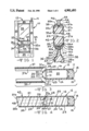
- FIG. 1 is an elevational view of a door assembly according to the present invention.
- FIG. 2 is a partial sectional view taken through line 2--2 of FIG. 1.
- FIGS. 3 and 4 are partial sectional views taken through lines 3--3 and 4--4 of FIG. 1, with FIG. 3 showing the skin members forming the central rail separated before assembly and FIG. 4 showing them joined following assembly with the foam core in place.
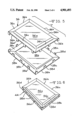
- FIGS. 5 and 6 are perspective views of the recessed panel portion of the central panel with FIG. 5 showing the skin members forming such recessed panel separated before assembly and FIG. 6 showing them joined so as to provide passages for the introduction of foam from the frame.
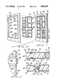
- FIG. 7 is a perspective view of an assembled door of a modified embodiment.
- FIG. 8 is a partial sectional view taken through line 8--8 of FIG. 7.
- FIG. 9 is a partial sectional view taken through line 9--9 of FIG. 7.
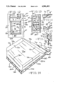
- FIG. 10 is a perspective view of one skin forming a portion of the frame and one skin forming a portion of the central panel of the embodiment of FIG. 7 showing such skins separated before assembly.
- FIG. 11 is an enlarged fragmentary view of the edge of one of the central panel skins of the embodiment of FIG. 7.
- FIG. 12 is a fragmentary elevational view of a modified door assembly including a modified central panel.
- FIG. 13 is a schematic view showing the motions required to position one of the central panel skins in one of the frame skins preparatory to assembling the modified door assembly of FIG. 12.
- FIG. 14 is a partial sectional view taken through line 14--14 of FIG. 12.
- FIG. 15 is a partial sectional view taken through line 15--15 of FIG. 12.
- FIG. 16 is a fragmentary perspective view of two skins forming the central panel of the embodiment of FIG. 12 showing the passages for introduction of foam from the frame.
- FIG. 17 is a partial sectional view taken through line 17--17 of FIG. 12.
- a door assembly generally designated by the numeral 10 having a frame generally designated 12.
- the frame is produced from an inner compression molded skin 14 and an outer compression molded skin 16 joined together at their outer edges by wooden stiles 18 which may extend around the entire periphery and form the exterior edges of the frame.
- the bottom of the frame may be provided with a door bottom and sill assembly of the type disclosed in U.S. Pat. No. 4,411,104 in place of a wooden stile 18.
- the skins 14 and 16 are positioned in generally parallel spaced relationship and cooperate with the wooden stiles 18 to define a cavity 20 in which a foam core 22 may be introduced.
- the frame is in the shape of a rectangle with a pair of vertical stiles 23 and a pair of horizontal rails 24.
- Each of the skins 14 and 16 extends from its respective exterior edge 15 or 17 adjacent the wooden stiles 18 to an interior edge 25 or 26.
- the interior edges 25 and 26 define an opening in which a central panel and, if desired, a window may be positioned.
- the cross-sectional configuration taken through the vertical stiles 23 is such that the skins 14 and 16 extend from exterior edges 15 and 17, respectively, toward the respective interior edges 25 and 26 following a generally planar path to a step 27 in the case of skin 14 and a step 28 in the case of skin 16.
- the arcuate segments curve inwardly toward the opposing skins; however, the edges 25 and 26 are spaced apart when the skins 14 and 16 are joined to the stiles 18 to form the frame.
- a series of spaced apart abutments 31 and 32 extend from the interior surface of the skins 14 and 16 at the respective steps.
- the portion of the skins forming the horizontal rails 24 have a similar configuration.
- the frame 12 secures and retains three separate units in the opening, namely, a window panel 33 which may be formed of single or multiple panes of glass and a double unit central panel 34.
- the central panel 34 in the embodiment of FIGS. 1-6 includes a first inner compression molded skin 35, a second inner compression molded skin 36, a first outer compression molded skin 37 and a second outer compression molded skin 38.
- the first inner skin 35 cooperates with the first outer skin 37 to form a horizontal rail 42 while the second inner skin 36 cooperates with the second outer skin 38 to form a recessed panel 44.
- the window panel 33 in the upper portion of the opening includes a pair of spaced apart glass window panes 46. As will be obvious to those skilled in the art, if desired, the window panes 46 could be replaced with other compression molded skins forming a panel similar to recessed panel 44.
- the first inner skin 35 and the first outer skin 37 extend the full distance between the vertical stiles 23 and terminate at edges 35a and 37a, respectively, which abut against the step 27 of skin 14 in the case of end 35a and step 28 of skin 16 in the case of end 37a.
- the skins 35 and 37 cooperate with each other and with the frame 12 to define a cavity 48.
- the interior edges 25 and 26, respectively, of skins 14 and 16 forming the frame 12 are spaced apart from one another so that upon introduction of foamable core material into the frame cavity 20, such foam material may flow to the cavity 48 so that a unitary foam core is produced for the frame and the rail portion 42 of the central panel as defined by the first inner skin 35 and first outer skin 37.
- the first inner skin 35 extends vertically from an upper arcuate segment 35b to an upper step 35c to a flat planar segment 35d to a lower step 35e and terminates at a lower arcuate segment 35f.
- the first outer skin 37 extends vertically from an arcuate segment 37b to an upper step 37c to a flat planar segment 37d to a lower step 37e and terminates at a lower arcuate segment 37f.
- the first inner skin 35 has a series of spaced apart abutments 39 extending inwardly toward the opposing first outer skin 37 in the area of the upper and lower steps 35c and 35e.
- the first outer skin 37 has a series of spaced apart abutments 40 extending inwardly toward the opposing first inner skin 35 in the area of the upper and lower steps 37c and 37e.
- the ends of the opposing arcuate segments 35b, 37b and 35f, 37f, are spaced from one another when the first inner skin 35 and first outer skin 37 are joined to the respective frame inner and outer skins 14 and 16 as shown in FIG. 4. As can be seen in FIG. 2, when such skins 35 and 37 are so positioned, the ends of the arcuate segments 35b and 37b engage the lower edge of the window panel 33 and the window panel 33 is supported on the upper set of abutments 39 and 40.
- the second inner skin 36 has a generally planar section 36a, peripheral edges 36b and curved segments 36c sloping toward the opposing second outer skin 38 between the planar section 36a and peripheral edges 36b.
- the second outer skin 38 has a generally planar section 38a, peripheral edges 38b and curved segments 36c sloping toward the opposing second inner skin 36 between the planar section 38a and peripheral edges 38b.
- a series of spaced apart tabs 38b which extend inwardly toward the second inner skin 36.
- each of the tabs 36d engages the opposing second outer skin 38 and each of the tabs 38d engages the opposing second inner skin 36 to maintain such skins in the proper spaced apart position for introducing foam in the spaces between the alternate spaced apart tabs 36d and 38d.
- the upper peripheral edges 36b and 38b of the joined second inner skin 36 and second outer skin 38 are positioned in the gap between the lower arcuate segments 35f and 37f of the first inner and outer skins 35 and 37.
- the abutments 39 and 40 serve to position the upper peripheral edges 36b and 38b so that the rail 42 is properly aligned relative to the recessed panel 44.
- That portion of the panel skins 14 and 16 forming the lower horizontal rail 24 has a cross sectional configuration similar to that shown for the vertical stiles 23 in FIG. 3 including the abutments 31 and 32.
- Such abutments 31 and 32 for the lower horizontal rail are engaged by and support the lower edges 36b and 38b of the second inner skin 36 and second outer skin 38 which extend into the gap between the interior edges 25 and 26.
- the abutments 31 and 32 along the portion of the panel skins 14 and 16 forming the vertical stiles 23 serve to position the peripheral edges 36b and 38b which extend into the gap between the interior edges 25 and 26 of such portion of panel skins 14 and 16.
- the spaces between the respective tabs 36d and 38d provide passages for the foam to flow into the cavity defined between the opposing second inner skin 36 and second outer skin 38.
- foam can enter the cavity between the second inner skin 36 and second outer skin 38 through either of the vertical stiles 23, the lower of the frame horizontal rails 24, and the horizontal rail 42 of the central panel.
- the foam insulating material may be introduced in flowable foamable form through a nozzle N inserted in an opening in the upper edge of the assembled skins 14 and 16 forming the frame and having the window panel and the members forming the central panel assembled therewith.
- the flowable foam insulating material will flow through the cavity 20 formed by the skins 14 and 16 and from the cavity 20, (1) through the gap formed by the ends 25 and 26 and into the cavity 48 formed by the first inner and outer skins 35 and 37, (2) through the spaces between the tabs 36d and 38d and into the cavity defined between the second inner and outer skins 36 and 38 and (3) with foam from cavity 48 into sealing engagement with the peripheral edge of the window panel 33.
- the nozzle N will be removed and the opening in the edge sealed.
- the foam insulating material can be rigid polyurethane foam or any reactive two component polymer or adhesively bonded polystyrene.
- the insulating material will be foamed in situ after introduction of foamable material into the cavity. Once the foam insulating material has cured, the components of the assembly are held together by the adhesion of the foam to the interior surfaces of the skins 14, 16, 35, 36, 37 and 38 and other components including the window panel 33.
- FIGS. 7-11 there is shown a modified embodiment of my new door assembly.
- a frame 12' having an inner skin 14' and an outer skin 16' which are joined together at their exterior edges by means of wooden stiles 18'.
- the frame 12' defines an opening in which a central panel 50 is affixed.
- the entire central panel 50 is produced using a single inner skin 51 and single outer skin 52.
- the inner frame skin 14' is similar in construction and configuration to the inner frame skin 14 of the embodiments of FIGS. 1-6.
- the inner skin 14' extends from an exterior edge 15' toward an interior edge 25' following a generally planar path to a step 27' with an arcuate segment 29' joining the step 27' with the interior edge 25'.
- the opposing skin 16' extends from an exterior edge 17' toward an interior edge 26' following a generally planar path to a step 28' with an arcuate segment 30' joining the step 28' with the interior edge 26'.
- the inner skin 14' has an interruption 49 in its arcuate segments 29' along each of the four interior edges.
- the number and location of interruptions 49 will be governed by the design of the inner skin 51.
- the inner skin 51 is formed as a single unitary piece. As shown it is provided with four rectangular recessed panels 54, a horizontal rail 56 and a vertical rail 58. As will be appreciated, there may be a greater or lesser number of recessed panels 54 and rails 56, 58, depending on the design desired for the central panel.
- a plurality of tabs 60 extend inwardly from the edge of the inner skin 51 toward the opposing skin.
- the opposing skin 52 may have a similar configuration, including tabs, and is, therefore, not shown in overall perspective in the drawings.
- the tabs serve to maintain the proper spacing between the inner and outer skins 51 and 52 with the spaces between the tabs 60 providing passageways from the cavity formed by the first and second skins 14' and 16' to the cavity between the assembled inner and outer skins 51 and 52.
- the portions of the skins forming the rails 56 and 58 extend exteriorly beyond the plane formed by the tabs 60 on the respective edges.
- the ends of the rails 56 and 58 fit into the gaps formed by the interruptions 49 with one end occupying the space formed by each such interruption 49.
- the number and location of each of the interruptions 49 should be the same as the number and location of the ends of the respective rails 56 and 58. In other words, there are two interruptions for each rail.
- the exterior ends of the rails 56 and 58 abut the steps 27' of skin 14'. Each of such ends has depending therefrom a hook 62 which engages an inwardly facing flange formed by the step 27' of the inner skin 14'.
- the skin 52 has a hook 63 depending from the exterior ends of those portions forming rails 56 and 58.
- Each of the hooks 63 engages an inwardly facing flange formed by each of the step 28' of outer skin 16' in the area of the interruptions 49.
- the inner and outer skins 51 and 52 forming the central panel are positioned between the inner and outer skins 14' and 16' forming the frame and are moved into engagement such that the skins 14' and 16' of the frame assembly engage the wooden stiles 18' forming the edges.
- the hooks 62 and 63 of the inner and outer skins 51 and 52 will be engaged with the flanges formed by the steps 27' and 28' respectively, of the frame skins 14' and 16'.
- the tabs 60 will abut against the edge of the opposing central panel outer skin 52 and the peripheral edges of the skins 51 and 52 will be positioned between the spaced apart interior edges 25' and 26' of the inner and outer frame skins 14' and 16'.
- Foamable polyurethane may then be introduced into the cavities to form the core.
- FIGS. 12-17 there is shown yet another embodiment in which the entire central panel is produced using a single inner skin 70 and a single outer skin 80, each of which is formed as a single unitary piece as in the embodiment of FIGS. 7-11.
- the central panel occupies only the lower portion of the opening defined by frame, with the upper portion of such opening having a window or, if desired, a separate panel.
- the frame 12" includes an inner skin 14" and an outer skin (not shown).
- the inner frame skin 14" defines a pair of vertical stiles 23" and upper and lower horizontal rails 24".
- the frame skin 14" extends from an exterior edge 15" adjacent a wooden stile (not shown) to an interior edge 25" following a generally planar path to a step 27".
- Arcuate segment 29" joins the step 27" to the interior edge 25".
- the arcuate segment 29" extends completely around the interior periphery of the skin 14" and there are no gaps or interruptions similar to the interruptions 49 in the embodiment of FIGS. 7-11.
- the central panel in this embodiment includes an inner skin 70 and an opposing outer skin 80.
- the inner skin 70 includes a horizontal rail portion 71 and a recessed panel portion 72.
- the recessed panel portion 72 has a generally planar section 72a, peripheral edges 72b and curved segments 72c sloping toward the opposing outer skin 80 between the planar section 72a and peripheral edges 72b.
- a series of spaced apart tabs 72d extend from the edges 72b toward the opposing outer skin 80 which is similar to the skin 70 including having tabs 80d extending inwardly from the edges 80b.
- Such rail portion 71 includes a lower arcuate segment 71a integral with and extending from the upper of the peripheral edges 72b, a lower step 71b, a planar portion 71c, an upper step 71d and an upper arcuate segment 71e which terminates at an upper free edge 71f.
- abutments 71g extending inwardly from the upper step 71d.
- the abutments provide support means for a window (not shown) which may be positioned in the upper part of the opening.
- the planar portion 71c of the rail portion 71 extends the full distance from the step 27" of one of the vertical stiles 23" to join with the step 27" of the opposite vertical stile 23" of the frame inner skin 14". This is a greater distance than the distance required to be spanned by the recessed panel portion 72 which must extend only slightly more than the distance between the interior edges 25" of the vertical stiles 23". Thus, the rail portion 71 projects exteriorly beyond the recessed panel portion 72.
- the portion of the inner skin 70 forming the ends of the rail 71 are on the outside surface of the arcuate segments 29" and thus, when assembled, cover those portions of such arcuate segments.
- those portions of the curved segments 72c adjacent the side and bottom peripheral edges 72b are under the arcuate segments 29" as they extend into the gap formed by the interior edge 25" of frame inner skin 14" and the interior edge of the opposing frame outer skin (not shown).
- the skins forming the outer surfaces of the respective frame and central panel will have a similar construction to the inner skins 14" and 70 respectively.
- the design is such as to permit communication between the cavity formed by the assembled frame inner skin 14" and outer skin (not shown) and the cavity formed by the assembled central panel inner skin 70 and outer skin 80.
- the foamable core material may be readily introduced throughout both cavities to form a unitary foam core.
- the door assembly in which the central panel members may be readily formed in any one of a variety of standard designs and assembled to members forming a frame with a foam core introduced throughout the frame and panel sections jointly.
- the foam utilized may be formed of polyurethane which has adhesive characteristics to join the compression molded skins together.
Abstract
Description
Claims (26)
Priority Applications (2)
| Application Number | Priority Date | Filing Date | Title |
|---|---|---|---|
| US07/284,494 US4901493A (en) | 1988-12-15 | 1988-12-15 | Door assembly |
| KR1019890015230A KR0144003B1 (en) | 1988-12-15 | 1989-10-21 | Improved door assembly |
Applications Claiming Priority (1)
| Application Number | Priority Date | Filing Date | Title |
|---|---|---|---|
| US07/284,494 US4901493A (en) | 1988-12-15 | 1988-12-15 | Door assembly |
Publications (1)
| Publication Number | Publication Date |
|---|---|
| US4901493A true US4901493A (en) | 1990-02-20 |
Family
ID=23090416
Family Applications (1)
| Application Number | Title | Priority Date | Filing Date |
|---|---|---|---|
| US07/284,494 Expired - Lifetime US4901493A (en) | 1988-12-15 | 1988-12-15 | Door assembly |
Country Status (2)
| Country | Link |
|---|---|
| US (1) | US4901493A (en) |
| KR (1) | KR0144003B1 (en) |
Cited By (47)
| Publication number | Priority date | Publication date | Assignee | Title |
|---|---|---|---|---|
| US5003745A (en) * | 1990-01-22 | 1991-04-02 | Fang Ho Tsung | Door of concavity surface |
| US5016414A (en) * | 1990-07-08 | 1991-05-21 | Wang Guo Chi | Imitated carved wooden door having three-dimensional panel structure |
| US5075059A (en) * | 1990-06-22 | 1991-12-24 | Pease Industries, Inc. | Method for forming panel door with simulated wood grains |
| WO1992010634A1 (en) * | 1990-12-15 | 1992-06-25 | Duraflex Limited | Door construction and kit therefor |
| US5239799A (en) * | 1991-08-28 | 1993-08-31 | The Stanley Works | Insulated door with synthetic resin skins |
| US5537789A (en) * | 1994-07-14 | 1996-07-23 | Therma-Tru Corp. | Compression molded door assembly |
| US5557899A (en) * | 1995-01-13 | 1996-09-24 | Materiaux De Construction 2 Plus 2 Inc. | Modular anti-warping door structure |
| EP0773342A1 (en) * | 1995-06-14 | 1997-05-14 | Nan Ya Plastics Corporation | Compression molded door assembly |
| US5704182A (en) * | 1995-06-06 | 1998-01-06 | Tapco International | Modular shutter assembly |
| US5775041A (en) * | 1995-07-21 | 1998-07-07 | Mcphillips Manufacturing Co. Inc. | Door entry system |
| US5887398A (en) * | 1997-03-17 | 1999-03-30 | Chen; Kuei Yung Wang | Synthetic door casement structure for patio doors and like, and method |
| US6035597A (en) * | 1997-09-12 | 2000-03-14 | Bay Mills Limited | Foam-filled decorative muntin bar for windows and the like |
| EP1094192A1 (en) | 1999-10-22 | 2001-04-25 | Nan Ya Plastics Corporation | Patio door with integral glazing frame |
| US6389768B1 (en) * | 1999-07-27 | 2002-05-21 | The Stanley Works | Molded plastic door skin |
| US20030066257A1 (en) * | 2001-10-04 | 2003-04-10 | Barry Shovlin | Method for manufacturing a door and door manufactured therefrom |
| US6584667B1 (en) * | 2000-07-25 | 2003-07-01 | Gregory Frumkin | Panel door construction and method of making same |
| US6619005B1 (en) * | 2002-04-16 | 2003-09-16 | Kuei Yung Wang Chen | Molded doors with large glass insert |
| US6622449B2 (en) | 2002-01-29 | 2003-09-23 | Mdf, Inc. | Door panel and method of forming same |
| US20040000120A1 (en) * | 2002-06-28 | 2004-01-01 | Gary Fagan | Composite door structure and method of forming a composite door structure |
| US6688063B1 (en) * | 2000-07-25 | 2004-02-10 | Larson Manufacturing Company | Wood core exterior door with mortise lock |
| US20040096535A1 (en) * | 2002-11-15 | 2004-05-20 | Hudecek Robert W. | Compression molding apparatus having replaceable mold inserts |
| US20040229010A1 (en) * | 2003-02-24 | 2004-11-18 | Clark Randy Jon | Thin-layer lignocellulose composites having increased resistance to moisture and methods of making the same |
| US20050028921A1 (en) * | 2003-07-01 | 2005-02-10 | Stroup Jon Christopher | Methods and systems for the automated manufacture of composite doors |
| US6922946B2 (en) | 1999-10-01 | 2005-08-02 | Odl, Incorporated | Window frame with both temporary and permanent connections |
| US20050257455A1 (en) * | 2004-03-17 | 2005-11-24 | Fagan Gary T | Wood-plastic composite door jamb and brickmold, and method of making same |
| US20050266222A1 (en) * | 2004-04-21 | 2005-12-01 | Clark Randy J | Fiber-reinforced composites and building structures comprising fiber-reinforced composites |
| US20060000173A1 (en) * | 2004-06-18 | 2006-01-05 | Edstrom Brian D | Composite structures having the appearance of knotty wood and methods of making such structures |
| US7007439B1 (en) | 2000-12-08 | 2006-03-07 | Larson Manufacturing Company Of South Dakota, Inc. | Door with lockset |
| US20060093745A1 (en) * | 2004-09-30 | 2006-05-04 | Nicholson John W | Treatment of wood for the production of building structures and other wood products |
| US7117639B2 (en) | 2000-12-27 | 2006-10-10 | Larson Manufacturing Company Of South Dakota, Inc. | Reversible door having mortise hardware |
| US20070110979A1 (en) * | 2004-04-21 | 2007-05-17 | Jeld-Wen, Inc. | Fiber-reinforced composite fire door |
| US20070160812A1 (en) * | 2006-01-06 | 2007-07-12 | Pickens Gregory A | Products and processes for forming door skins |
| WO2007117389A2 (en) * | 2006-03-31 | 2007-10-18 | Durakon Industries, Inc. | Composite plug door for use on railcars |
| US20080107148A1 (en) * | 2003-11-04 | 2008-05-08 | L&P Property Management Company | Thermal properties testing apparatus and methods |
| US7390447B1 (en) | 2003-05-30 | 2008-06-24 | Jeld-Wen, Inc. | Molded thin-layer lignocellulosic composites made using hybrid poplar and methods of making same |
| US20090113830A1 (en) * | 2007-11-07 | 2009-05-07 | Jeld-Wen, Inc. | Composite garage doors and processes for making such doors |
| US20090297818A1 (en) * | 2008-05-29 | 2009-12-03 | Jeld-Wen, Inc. | Primer compositions and methods of making the same |
| US20090315437A1 (en) * | 2005-11-10 | 2009-12-24 | Hoong Thye Eldon Lee | Ceramic Doors and Boards and Applications Thereof |
| US7721500B2 (en) | 2002-10-31 | 2010-05-25 | Jeld-Wen, Inc. | Multi-layered fire door and method for making the same |
| US20100151229A1 (en) * | 2008-12-11 | 2010-06-17 | Jeld-Wen, Inc. | Thin-layer lignocellulose composites and methods of making the same |
| US20100199570A1 (en) * | 2007-04-13 | 2010-08-12 | Turner Daniel S | Apparatus and method of fabricating a door |
| US7943070B1 (en) | 2003-05-05 | 2011-05-17 | Jeld-Wen, Inc. | Molded thin-layer lignocellulose composites having reduced thickness and methods of making same |
| US8596022B2 (en) * | 2008-08-01 | 2013-12-03 | Everlast Doors Industries, Sa | Metal door |
| US20160108660A1 (en) * | 2013-05-24 | 2016-04-21 | Vapor Europe S.R.L. | Door Leaf Device for Mass Transportation Vehicles and Method for the Production of Such a Door |
| US9493980B1 (en) * | 2010-11-23 | 2016-11-15 | Jerry G. Crittenden | Stile and rail door with hollow core stiles and rails for perimeter air flow |
| US9845637B1 (en) * | 2015-12-15 | 2017-12-19 | Decore-Ative Specialties, Inc. | Cabinet door assembly and manufacturing thereof |
| US10156091B1 (en) * | 2010-11-23 | 2018-12-18 | Jerry G. Crittenden | Margin air flow door for preventing pressure build up |
Citations (46)
| Publication number | Priority date | Publication date | Assignee | Title |
|---|---|---|---|---|
| US653400A (en) * | 1899-12-18 | 1900-07-10 | John W Rapp | Fireproof door. |
| US751435A (en) * | 1904-02-02 | Metallic furniture | ||
| US1183842A (en) * | 1913-11-14 | 1916-05-23 | Jared E Alling | Door. |
| US1249814A (en) * | 1917-03-29 | 1917-12-11 | Otho M Otte | Sheet-metal door. |
| US2849758A (en) * | 1955-04-18 | 1958-09-02 | Glenn V Plumley | Faced honeycomb building material |
| US2871056A (en) * | 1953-11-30 | 1959-01-27 | Fruehauf Trailer Co | Plastic doors and door frames for trailers |
| US2890977A (en) * | 1952-09-18 | 1959-06-16 | Bayer Erich | Process for the production of doors from plastics in a single operation |
| US2924860A (en) * | 1957-03-25 | 1960-02-16 | Parham | Thermally insulating door |
| US3153817A (en) * | 1961-05-29 | 1964-10-27 | Pease Woodwork Company Inc | Metal door with plastic core |
| US3225505A (en) * | 1963-08-13 | 1965-12-28 | Lucian C Lytz | Fire-resistant door |
| US3250041A (en) * | 1963-08-27 | 1966-05-10 | Dorplastex A G | Door structures |
| US3299595A (en) * | 1962-07-18 | 1967-01-24 | Werz Furnier Sperrholz | Compound door |
| US3402520A (en) * | 1966-12-23 | 1968-09-24 | Home Comfort Products Co | Panel with foamed-in-place core |
| US3404502A (en) * | 1964-10-19 | 1968-10-08 | Ralph G. Miller | Decorative hollow doors |
| US3498001A (en) * | 1967-08-21 | 1970-03-03 | Cardinal Of Adrian | Enclosure panel |
| US3512304A (en) * | 1968-08-01 | 1970-05-19 | Morgan Co | Insulated panel door |
| US3546841A (en) * | 1968-12-26 | 1970-12-15 | Home Comfort Products Co | Fabricated doors,panels and the like |
| US3593479A (en) * | 1969-01-31 | 1971-07-20 | Bird & Son | Molded plastic siding units |
| US3772241A (en) * | 1966-07-20 | 1973-11-13 | Rohm & Haas | Unsaturated polyester resinous compositions |
| US3883612A (en) * | 1971-06-07 | 1975-05-13 | Scm Corp | Low-shrink thermosetting polymers |
| FR2258510A1 (en) * | 1974-01-21 | 1975-08-18 | Cegedur | Foam filled sections for door and window frames - are folded metal sheet containing expanded polyurethane foam |
| GB1420244A (en) * | 1973-05-09 | 1976-01-07 | Marsden Co Ltd W | Laminate-faced timber-framed structures |
| US3950894A (en) * | 1974-02-22 | 1976-04-20 | Structural Plastics Incorporated | Reinforced polyester door |
| US3961012A (en) * | 1975-01-06 | 1976-06-01 | Structural Plastics Incorporated | Method of making resin impregnated glass fiber article |
| FR2304763A1 (en) * | 1975-03-19 | 1976-10-15 | Pillet Michel | Plastic shutter made of two halves filled with foam - resistant to weather and providing sound and heat insulation |
| SU551432A1 (en) * | 1975-12-01 | 1977-03-25 | Ленинградский зональный научно-исследовательский и проектный институт типового и экспериментального проектирования жилых и общественных зданий | Wall panel |
| US4022644A (en) * | 1974-10-24 | 1977-05-10 | The Dow Chemical Company | Foam structures and component therefore |
| GB1487309A (en) * | 1973-11-01 | 1977-09-28 | Newbourne Watson Ltd | Doors |
| SU604937A1 (en) * | 1976-12-29 | 1978-04-30 | Ордена Трудового Красного Знамени Центральный Научно-Исследовательский Институт Строительных Конструкций Им.В.А.Кучеренко | Laminated panel |
| US4132042A (en) * | 1978-01-13 | 1979-01-02 | Vincent Di Maio | Door structure and method for forming such structure |
| US4152876A (en) * | 1978-02-14 | 1979-05-08 | The Stanley Works | Method of making and installing trimmable insulated steel faced entry door |
| GB2044316A (en) * | 1979-03-16 | 1980-10-15 | Precision Metal Forming Ltd | Double-skin Wall or Roof Panel |
| US4236365A (en) * | 1978-08-25 | 1980-12-02 | Wood Processes, Oregon Ltd. | Rigid building component and method of manufacture |
| GB2057037A (en) * | 1979-08-24 | 1981-03-25 | Tippmann E | Insulated door and window frames |
| US4265067A (en) * | 1979-05-07 | 1981-05-05 | Masonite Corporation | Foamed plastic core door |
| US4311183A (en) * | 1976-01-26 | 1982-01-19 | Walter Herbst | Combination storm and screen self storing door |
| US4327535A (en) * | 1980-02-21 | 1982-05-04 | Peachtree Doors, Inc. | Door with glass panel |
| US4374693A (en) * | 1977-04-27 | 1983-02-22 | Pitt William V | Method of manufacturing atmospheric resistant doors |
| US4429493A (en) * | 1982-09-27 | 1984-02-07 | Lst Corporation | Astragal housing seal and lock |
| BE898855A (en) * | 1984-02-07 | 1984-05-30 | Therma Tru Corp | Timber framed doors with a cellular core enclosed by moulded panels - to suppress splitting or warping by humidity variations |
| US4496201A (en) * | 1982-07-23 | 1985-01-29 | Umc Industries, Inc. | Closure such as a glass door for a refrigeration or freezer |
| US4546585A (en) * | 1983-08-02 | 1985-10-15 | Peachtree Doors, Inc. | Door panel and method of making |
| US4550540A (en) * | 1983-01-07 | 1985-11-05 | Therma-Tru Corp. | Compression molded door assembly |
| US4635421A (en) * | 1985-04-17 | 1987-01-13 | Eliason Corporation | Molded door |
| US4720951A (en) * | 1986-03-24 | 1988-01-26 | Therma-Tru Corp. | Frame assembly for doors, windows and the like |
| US4811538A (en) * | 1987-10-20 | 1989-03-14 | Georgia-Pacific Corporation | Fire-resistant door |
-
1988
- 1988-12-15 US US07/284,494 patent/US4901493A/en not_active Expired - Lifetime
-
1989
- 1989-10-21 KR KR1019890015230A patent/KR0144003B1/en not_active IP Right Cessation
Patent Citations (46)
| Publication number | Priority date | Publication date | Assignee | Title |
|---|---|---|---|---|
| US751435A (en) * | 1904-02-02 | Metallic furniture | ||
| US653400A (en) * | 1899-12-18 | 1900-07-10 | John W Rapp | Fireproof door. |
| US1183842A (en) * | 1913-11-14 | 1916-05-23 | Jared E Alling | Door. |
| US1249814A (en) * | 1917-03-29 | 1917-12-11 | Otho M Otte | Sheet-metal door. |
| US2890977A (en) * | 1952-09-18 | 1959-06-16 | Bayer Erich | Process for the production of doors from plastics in a single operation |
| US2871056A (en) * | 1953-11-30 | 1959-01-27 | Fruehauf Trailer Co | Plastic doors and door frames for trailers |
| US2849758A (en) * | 1955-04-18 | 1958-09-02 | Glenn V Plumley | Faced honeycomb building material |
| US2924860A (en) * | 1957-03-25 | 1960-02-16 | Parham | Thermally insulating door |
| US3153817A (en) * | 1961-05-29 | 1964-10-27 | Pease Woodwork Company Inc | Metal door with plastic core |
| US3299595A (en) * | 1962-07-18 | 1967-01-24 | Werz Furnier Sperrholz | Compound door |
| US3225505A (en) * | 1963-08-13 | 1965-12-28 | Lucian C Lytz | Fire-resistant door |
| US3250041A (en) * | 1963-08-27 | 1966-05-10 | Dorplastex A G | Door structures |
| US3404502A (en) * | 1964-10-19 | 1968-10-08 | Ralph G. Miller | Decorative hollow doors |
| US3772241A (en) * | 1966-07-20 | 1973-11-13 | Rohm & Haas | Unsaturated polyester resinous compositions |
| US3402520A (en) * | 1966-12-23 | 1968-09-24 | Home Comfort Products Co | Panel with foamed-in-place core |
| US3498001A (en) * | 1967-08-21 | 1970-03-03 | Cardinal Of Adrian | Enclosure panel |
| US3512304A (en) * | 1968-08-01 | 1970-05-19 | Morgan Co | Insulated panel door |
| US3546841A (en) * | 1968-12-26 | 1970-12-15 | Home Comfort Products Co | Fabricated doors,panels and the like |
| US3593479A (en) * | 1969-01-31 | 1971-07-20 | Bird & Son | Molded plastic siding units |
| US3883612A (en) * | 1971-06-07 | 1975-05-13 | Scm Corp | Low-shrink thermosetting polymers |
| GB1420244A (en) * | 1973-05-09 | 1976-01-07 | Marsden Co Ltd W | Laminate-faced timber-framed structures |
| GB1487309A (en) * | 1973-11-01 | 1977-09-28 | Newbourne Watson Ltd | Doors |
| FR2258510A1 (en) * | 1974-01-21 | 1975-08-18 | Cegedur | Foam filled sections for door and window frames - are folded metal sheet containing expanded polyurethane foam |
| US3950894A (en) * | 1974-02-22 | 1976-04-20 | Structural Plastics Incorporated | Reinforced polyester door |
| US4022644A (en) * | 1974-10-24 | 1977-05-10 | The Dow Chemical Company | Foam structures and component therefore |
| US3961012A (en) * | 1975-01-06 | 1976-06-01 | Structural Plastics Incorporated | Method of making resin impregnated glass fiber article |
| FR2304763A1 (en) * | 1975-03-19 | 1976-10-15 | Pillet Michel | Plastic shutter made of two halves filled with foam - resistant to weather and providing sound and heat insulation |
| SU551432A1 (en) * | 1975-12-01 | 1977-03-25 | Ленинградский зональный научно-исследовательский и проектный институт типового и экспериментального проектирования жилых и общественных зданий | Wall panel |
| US4311183A (en) * | 1976-01-26 | 1982-01-19 | Walter Herbst | Combination storm and screen self storing door |
| SU604937A1 (en) * | 1976-12-29 | 1978-04-30 | Ордена Трудового Красного Знамени Центральный Научно-Исследовательский Институт Строительных Конструкций Им.В.А.Кучеренко | Laminated panel |
| US4374693A (en) * | 1977-04-27 | 1983-02-22 | Pitt William V | Method of manufacturing atmospheric resistant doors |
| US4132042A (en) * | 1978-01-13 | 1979-01-02 | Vincent Di Maio | Door structure and method for forming such structure |
| US4152876A (en) * | 1978-02-14 | 1979-05-08 | The Stanley Works | Method of making and installing trimmable insulated steel faced entry door |
| US4236365A (en) * | 1978-08-25 | 1980-12-02 | Wood Processes, Oregon Ltd. | Rigid building component and method of manufacture |
| GB2044316A (en) * | 1979-03-16 | 1980-10-15 | Precision Metal Forming Ltd | Double-skin Wall or Roof Panel |
| US4265067A (en) * | 1979-05-07 | 1981-05-05 | Masonite Corporation | Foamed plastic core door |
| GB2057037A (en) * | 1979-08-24 | 1981-03-25 | Tippmann E | Insulated door and window frames |
| US4327535A (en) * | 1980-02-21 | 1982-05-04 | Peachtree Doors, Inc. | Door with glass panel |
| US4496201A (en) * | 1982-07-23 | 1985-01-29 | Umc Industries, Inc. | Closure such as a glass door for a refrigeration or freezer |
| US4429493A (en) * | 1982-09-27 | 1984-02-07 | Lst Corporation | Astragal housing seal and lock |
| US4550540A (en) * | 1983-01-07 | 1985-11-05 | Therma-Tru Corp. | Compression molded door assembly |
| US4546585A (en) * | 1983-08-02 | 1985-10-15 | Peachtree Doors, Inc. | Door panel and method of making |
| BE898855A (en) * | 1984-02-07 | 1984-05-30 | Therma Tru Corp | Timber framed doors with a cellular core enclosed by moulded panels - to suppress splitting or warping by humidity variations |
| US4635421A (en) * | 1985-04-17 | 1987-01-13 | Eliason Corporation | Molded door |
| US4720951A (en) * | 1986-03-24 | 1988-01-26 | Therma-Tru Corp. | Frame assembly for doors, windows and the like |
| US4811538A (en) * | 1987-10-20 | 1989-03-14 | Georgia-Pacific Corporation | Fire-resistant door |
Cited By (75)
| Publication number | Priority date | Publication date | Assignee | Title |
|---|---|---|---|---|
| US5003745A (en) * | 1990-01-22 | 1991-04-02 | Fang Ho Tsung | Door of concavity surface |
| EP0489994A1 (en) * | 1990-01-22 | 1992-06-17 | Ho-Tsung Fang | Door of concave surface |
| US5075059A (en) * | 1990-06-22 | 1991-12-24 | Pease Industries, Inc. | Method for forming panel door with simulated wood grains |
| US5016414A (en) * | 1990-07-08 | 1991-05-21 | Wang Guo Chi | Imitated carved wooden door having three-dimensional panel structure |
| WO1992010634A1 (en) * | 1990-12-15 | 1992-06-25 | Duraflex Limited | Door construction and kit therefor |
| US5239799A (en) * | 1991-08-28 | 1993-08-31 | The Stanley Works | Insulated door with synthetic resin skins |
| US5369869A (en) * | 1991-08-28 | 1994-12-06 | The Stanley Works | Method for making an insulated door with synthetic resin skins |
| US5537789A (en) * | 1994-07-14 | 1996-07-23 | Therma-Tru Corp. | Compression molded door assembly |
| USRE36240E (en) * | 1994-07-14 | 1999-06-29 | Therma-Tru Corporation | Compression molded door assembly |
| US5557899A (en) * | 1995-01-13 | 1996-09-24 | Materiaux De Construction 2 Plus 2 Inc. | Modular anti-warping door structure |
| US5704182A (en) * | 1995-06-06 | 1998-01-06 | Tapco International | Modular shutter assembly |
| US6141938A (en) * | 1995-06-06 | 2000-11-07 | Tapco International Corporation | Modular shutter assembly including a die cut panel |
| US6397540B1 (en) | 1995-06-06 | 2002-06-04 | Tapco International Corporation | Modular shutter assembly including a die cut panel |
| US6023905A (en) * | 1995-06-06 | 2000-02-15 | Tapco International Corporation | Modular shutter assembly including a die cut panel |
| EP0773342A1 (en) * | 1995-06-14 | 1997-05-14 | Nan Ya Plastics Corporation | Compression molded door assembly |
| US5644870A (en) * | 1995-06-14 | 1997-07-08 | Nan Ya Plastics Corporation | Compression molded door assembly |
| US5775041A (en) * | 1995-07-21 | 1998-07-07 | Mcphillips Manufacturing Co. Inc. | Door entry system |
| US5887398A (en) * | 1997-03-17 | 1999-03-30 | Chen; Kuei Yung Wang | Synthetic door casement structure for patio doors and like, and method |
| US6035597A (en) * | 1997-09-12 | 2000-03-14 | Bay Mills Limited | Foam-filled decorative muntin bar for windows and the like |
| US6192651B1 (en) | 1997-09-12 | 2001-02-27 | Bay Mills Limited | Method of forming foam-filled decorative muntin bar for windows and the like |
| US6389768B1 (en) * | 1999-07-27 | 2002-05-21 | The Stanley Works | Molded plastic door skin |
| US7331142B2 (en) | 1999-10-01 | 2008-02-19 | Odl, Incorporated | Window frame with ship and install orientations |
| US6922946B2 (en) | 1999-10-01 | 2005-08-02 | Odl, Incorporated | Window frame with both temporary and permanent connections |
| EP1094192A1 (en) | 1999-10-22 | 2001-04-25 | Nan Ya Plastics Corporation | Patio door with integral glazing frame |
| US6584667B1 (en) * | 2000-07-25 | 2003-07-01 | Gregory Frumkin | Panel door construction and method of making same |
| US6684590B2 (en) | 2000-07-25 | 2004-02-03 | Gregory Frumkin | Panel door construction and method of making same |
| US6688063B1 (en) * | 2000-07-25 | 2004-02-10 | Larson Manufacturing Company | Wood core exterior door with mortise lock |
| US7007439B1 (en) | 2000-12-08 | 2006-03-07 | Larson Manufacturing Company Of South Dakota, Inc. | Door with lockset |
| US7117639B2 (en) | 2000-12-27 | 2006-10-10 | Larson Manufacturing Company Of South Dakota, Inc. | Reversible door having mortise hardware |
| US20030066257A1 (en) * | 2001-10-04 | 2003-04-10 | Barry Shovlin | Method for manufacturing a door and door manufactured therefrom |
| US20050223674A1 (en) * | 2001-10-04 | 2005-10-13 | Masonite Corporation | Method for manufacturing a door and door manufactured therefrom |
| US6622449B2 (en) | 2002-01-29 | 2003-09-23 | Mdf, Inc. | Door panel and method of forming same |
| US6619005B1 (en) * | 2002-04-16 | 2003-09-16 | Kuei Yung Wang Chen | Molded doors with large glass insert |
| US7337544B2 (en) | 2002-06-28 | 2008-03-04 | Masonite International Corporation | Method of forming a composite door structure |
| US20040000120A1 (en) * | 2002-06-28 | 2004-01-01 | Gary Fagan | Composite door structure and method of forming a composite door structure |
| US20070119114A1 (en) * | 2002-06-28 | 2007-05-31 | Gary Fagan | Composite door structure and method of forming a composite door structure |
| US7178308B2 (en) * | 2002-06-28 | 2007-02-20 | Masonite International Corporation | Composite door structure and method of forming a composite door structure |
| US7721500B2 (en) | 2002-10-31 | 2010-05-25 | Jeld-Wen, Inc. | Multi-layered fire door and method for making the same |
| US20040096535A1 (en) * | 2002-11-15 | 2004-05-20 | Hudecek Robert W. | Compression molding apparatus having replaceable mold inserts |
| US7399438B2 (en) | 2003-02-24 | 2008-07-15 | Jeld-Wen, Inc. | Thin-layer lignocellulose composites having increased resistance to moisture and methods of making the same |
| US8679386B2 (en) | 2003-02-24 | 2014-03-25 | Jeld-Wen, Inc. | Thin-layer lignocellulose composites having increased resistance to moisture and methods of making the same |
| US7919186B2 (en) | 2003-02-24 | 2011-04-05 | Jeld-Wen, Inc. | Thin-layer lignocellulose composites having increased resistance to moisture |
| US20080286581A1 (en) * | 2003-02-24 | 2008-11-20 | Jeld-Wen, Inc. | Thin-layer lignocellulose composites having increased resistance to moisture and methods of making the same |
| US20040229010A1 (en) * | 2003-02-24 | 2004-11-18 | Clark Randy Jon | Thin-layer lignocellulose composites having increased resistance to moisture and methods of making the same |
| US7943070B1 (en) | 2003-05-05 | 2011-05-17 | Jeld-Wen, Inc. | Molded thin-layer lignocellulose composites having reduced thickness and methods of making same |
| US7390447B1 (en) | 2003-05-30 | 2008-06-24 | Jeld-Wen, Inc. | Molded thin-layer lignocellulosic composites made using hybrid poplar and methods of making same |
| US20050028921A1 (en) * | 2003-07-01 | 2005-02-10 | Stroup Jon Christopher | Methods and systems for the automated manufacture of composite doors |
| US7501037B2 (en) | 2003-07-01 | 2009-03-10 | Jeld-Wen, Inc. | Methods and systems for the automated manufacture of composite doors |
| US20080107148A1 (en) * | 2003-11-04 | 2008-05-08 | L&P Property Management Company | Thermal properties testing apparatus and methods |
| US20050257455A1 (en) * | 2004-03-17 | 2005-11-24 | Fagan Gary T | Wood-plastic composite door jamb and brickmold, and method of making same |
| US20050266222A1 (en) * | 2004-04-21 | 2005-12-01 | Clark Randy J | Fiber-reinforced composites and building structures comprising fiber-reinforced composites |
| US20070110979A1 (en) * | 2004-04-21 | 2007-05-17 | Jeld-Wen, Inc. | Fiber-reinforced composite fire door |
| US20060000173A1 (en) * | 2004-06-18 | 2006-01-05 | Edstrom Brian D | Composite structures having the appearance of knotty wood and methods of making such structures |
| US9339943B2 (en) | 2004-09-30 | 2016-05-17 | Jeld-Wen, Inc. | Treatment of wood for the production of building structures and other wood products |
| US8974910B2 (en) | 2004-09-30 | 2015-03-10 | Jeld-Wen, Inc. | Treatment of wood for the production of building structures and other wood products |
| US20060093745A1 (en) * | 2004-09-30 | 2006-05-04 | Nicholson John W | Treatment of wood for the production of building structures and other wood products |
| US20090315437A1 (en) * | 2005-11-10 | 2009-12-24 | Hoong Thye Eldon Lee | Ceramic Doors and Boards and Applications Thereof |
| US8931238B2 (en) * | 2005-11-10 | 2015-01-13 | Hoong Thye Eldon Lee | Ceramic doors and boards and applications thereof |
| US20070160812A1 (en) * | 2006-01-06 | 2007-07-12 | Pickens Gregory A | Products and processes for forming door skins |
| WO2007117389A2 (en) * | 2006-03-31 | 2007-10-18 | Durakon Industries, Inc. | Composite plug door for use on railcars |
| WO2007117389A3 (en) * | 2006-03-31 | 2008-10-02 | Durakon Ind Inc | Composite plug door for use on railcars |
| US20070245672A1 (en) * | 2006-03-31 | 2007-10-25 | Durakon Industries, Inc. | Composite plug door for use on railcars |
| US20100199570A1 (en) * | 2007-04-13 | 2010-08-12 | Turner Daniel S | Apparatus and method of fabricating a door |
| US20090113830A1 (en) * | 2007-11-07 | 2009-05-07 | Jeld-Wen, Inc. | Composite garage doors and processes for making such doors |
| US20090297818A1 (en) * | 2008-05-29 | 2009-12-03 | Jeld-Wen, Inc. | Primer compositions and methods of making the same |
| US8596022B2 (en) * | 2008-08-01 | 2013-12-03 | Everlast Doors Industries, Sa | Metal door |
| US9719289B2 (en) | 2008-08-01 | 2017-08-01 | Everlast Doors Industries, Inc. | Metal door |
| US8058193B2 (en) | 2008-12-11 | 2011-11-15 | Jeld-Wen, Inc. | Thin-layer lignocellulose composites and methods of making the same |
| US20100151229A1 (en) * | 2008-12-11 | 2010-06-17 | Jeld-Wen, Inc. | Thin-layer lignocellulose composites and methods of making the same |
| US9493980B1 (en) * | 2010-11-23 | 2016-11-15 | Jerry G. Crittenden | Stile and rail door with hollow core stiles and rails for perimeter air flow |
| US10156091B1 (en) * | 2010-11-23 | 2018-12-18 | Jerry G. Crittenden | Margin air flow door for preventing pressure build up |
| US20160108660A1 (en) * | 2013-05-24 | 2016-04-21 | Vapor Europe S.R.L. | Door Leaf Device for Mass Transportation Vehicles and Method for the Production of Such a Door |
| US9845637B1 (en) * | 2015-12-15 | 2017-12-19 | Decore-Ative Specialties, Inc. | Cabinet door assembly and manufacturing thereof |
| US10900278B1 (en) | 2015-12-15 | 2021-01-26 | Decore-Ative Specialties, Inc. | Cabinet door assembly and manufacturing thereof |
| US10975614B1 (en) | 2015-12-15 | 2021-04-13 | Decore-Ative Specialties, Inc. | Cabinet door assembly and manufacturing thereof |
Also Published As
| Publication number | Publication date |
|---|---|
| KR0144003B1 (en) | 1998-09-15 |
| KR900010180A (en) | 1990-07-06 |
Similar Documents
| Publication | Publication Date | Title |
|---|---|---|
| US4901493A (en) | Door assembly | |
| US4850168A (en) | Frame assembly for doors, windows and the like | |
| US4662145A (en) | Prefabricated curtain wall assembly having both window and spandrel units, and method of installation | |
| US5099624A (en) | Window systems | |
| US5074087A (en) | Doors of composite construction | |
| US4920718A (en) | Integral door light and related door construction | |
| US4720951A (en) | Frame assembly for doors, windows and the like | |
| US3729889A (en) | Modular insulated panel system | |
| US4546585A (en) | Door panel and method of making | |
| US4662136A (en) | Prefabricated curtain wall assembly having both window and spandrel units | |
| US4084361A (en) | Frame and sash for doors and windows | |
| US4167088A (en) | Doors for patios and the like | |
| US4614069A (en) | Prefabricated curtain wall assembly | |
| US4977722A (en) | Frame system | |
| US4854365A (en) | Sectional-type door | |
| CA2067512A1 (en) | Insulated door with synthetic resin skins and method of making same | |
| US4662135A (en) | Device for mounting a prefabricating curtain wall unit to a floor structure | |
| US5339522A (en) | Method for constructing modular doors | |
| US5584154A (en) | Closure and sealing joint for incorporation in such a closure | |
| CA1050825A (en) | Glazing system | |
| US6675537B2 (en) | Double hung plastic window frame | |
| US4070838A (en) | Clip for assembling screens, panels or bulkhead sections | |
| GB2315292A (en) | Panel door having edge protection for the cut panels | |
| EP1094192B1 (en) | Patio door with integral glazing frame | |
| CA1118287A (en) | Glass panel structure |
Legal Events
| Date | Code | Title | Description |
|---|---|---|---|
| AS | Assignment |
Owner name: THERMA-TRU CORP., OHIO Free format text: ASSIGNMENT OF ASSIGNORS INTEREST.;ASSIGNOR:THORN, JOHN F.;REEL/FRAME:005024/0802 Effective date: 19881208 |
|
| STCF | Information on status: patent grant |
Free format text: PATENTED CASE |
|
| FEPP | Fee payment procedure |
Free format text: PAYOR NUMBER ASSIGNED (ORIGINAL EVENT CODE: ASPN); ENTITY STATUS OF PATENT OWNER: LARGE ENTITY |
|
| FPAY | Fee payment |
Year of fee payment: 4 |
|
| FPAY | Fee payment |
Year of fee payment: 8 |
|
| AS | Assignment |
Owner name: THERMA-TRU HOLDINGS, INC., OHIO Free format text: ASSIGNMENT OF ASSIGNORS INTEREST;ASSIGNOR:THERMA-TRU CORP.;REEL/FRAME:010832/0638 Effective date: 20000508 |
|
| AS | Assignment |
Owner name: THERMA-TRU CORP., OHIO Free format text: CHANGE OF NAME;ASSIGNOR:THERMA-TRU HOLDINGS, INC.;REEL/FRAME:011923/0363 Effective date: 20000509 |
|
| FPAY | Fee payment |
Year of fee payment: 12 |
|
| AS | Assignment |
Owner name: TT TECHNOLOGIES, INC., OHIO Free format text: ASSIGNMENT OF ASSIGNORS INTEREST;ASSIGNOR:THERMA-TRU CORPORATION;REEL/FRAME:012188/0750 Effective date: 20010101 |
|
| AS | Assignment |
Owner name: THERMA-TRU CORP., OHIO Free format text: MERGER;ASSIGNOR:TT TECHNOLOGIES INC.;REEL/FRAME:020403/0797 Effective date: 20071226 |