US4901365A - Method of searching binary images to find search regions in which straight lines may be found - Google Patents

Method of searching binary images to find search regions in which straight lines may be found Download PDF

Info

Publication number
US4901365A
US4901365A US07/286,411 US28641188A US4901365A US 4901365 A US4901365 A US 4901365A US 28641188 A US28641188 A US 28641188A US 4901365 A US4901365 A US 4901365A
Authority
US
United States
Prior art keywords
scans
search
scan
scanning
binary
Prior art date
Legal status (The legal status is an assumption and is not a legal conclusion. Google has not performed a legal analysis and makes no representation as to the accuracy of the status listed.)
Expired - Lifetime
Application number
US07/286,411
Inventor
Stewart B. Kelland
Current Assignee (The listed assignees may be inaccurate. Google has not performed a legal analysis and makes no representation or warranty as to the accuracy of the list.)
NCR Voyix Corp
Original Assignee
NCR Corp
Priority date (The priority date is an assumption and is not a legal conclusion. Google has not performed a legal analysis and makes no representation as to the accuracy of the date listed.)
Filing date
Publication date
Application filed by NCR Corp filed Critical NCR Corp
Priority to US07/286,411 priority Critical patent/US4901365A/en
Assigned to NCR CORPORATION, A CORP. OF MD reassignment NCR CORPORATION, A CORP. OF MD ASSIGNMENT OF ASSIGNORS INTEREST. Assignors: KELLAND, STEWART B.
Priority to CA000599525A priority patent/CA1316605C/en
Priority to JP1326216A priority patent/JPH02224187A/en
Priority to DE68913475T priority patent/DE68913475T2/en
Priority to EP89313265A priority patent/EP0375352B1/en
Application granted granted Critical
Publication of US4901365A publication Critical patent/US4901365A/en
Anticipated expiration legal-status Critical
Expired - Lifetime legal-status Critical Current

Links

Images

Classifications

    • GPHYSICS
    • G06COMPUTING; CALCULATING OR COUNTING
    • G06VIMAGE OR VIDEO RECOGNITION OR UNDERSTANDING
    • G06V10/00Arrangements for image or video recognition or understanding
    • G06V10/40Extraction of image or video features
    • G06V10/44Local feature extraction by analysis of parts of the pattern, e.g. by detecting edges, contours, loops, corners, strokes or intersections; Connectivity analysis, e.g. of connected components
    • GPHYSICS
    • G06COMPUTING; CALCULATING OR COUNTING
    • G06VIMAGE OR VIDEO RECOGNITION OR UNDERSTANDING
    • G06V30/00Character recognition; Recognising digital ink; Document-oriented image-based pattern recognition
    • G06V30/10Character recognition

Definitions

  • This invention relates to a method of searching a matrix of binary data to find search regions in which long straight lines may be found, with the straight lines being those which are perpendicular to the original direction of scanning which produced the matrix of binary data.
  • the image data consists of a plurality of pixels or picture elements obtained at a scanning line associated with the scanning device.
  • the pixels associated with successive scans obtained at the scanning line comprise the matrix of image data associated with the item or document.
  • the image data is processed by conventional circuitry to eliminate "noise” and the like, and to also threshold the image data to produce a binary matrix of data.
  • each pixel of image data which may comprise an eight bit gray scale value which is obtained from the scanning line, is reduced, by thresholding, to a binary "1" or a binary "0".
  • a binary 1 may indicate the presence of data, while a binary 0 indicates the background or the absence of data.
  • the image data about a document is thresholded to a matrix of binary data.
  • One of the problems with using a matrix of binary data is that it is often difficult to find what is looked for within the matrix. In other words, there may be a lot of extraneous binary data in the matrix in addition to what is sought. For example, one may look for certain lines in the matrix of data. In this regard, long lines which are parallel to the original direction of scanning are not difficult to find, whereas, long lines which are perpendicular to the original scan line are difficult to find. For example, if the scanning is done along successive columns, long lines which are parallel to the direction of scanning are easy to find. In other words, a long string of binary ones will be found in a particular column or adjacent columns, indicating the presence of a long line. However, if the long line is perpendicular to the original scanning direction, it means that a portion of the line will extend over many columns of data, making the search for this long line difficult.
  • An advantage of the present invention is that it facilitates the location of long lines within a matrix of binary pixels associated with an image of a document.
  • Another advantage of the present invention is that it facilitates the identification of certain documents. For example, certain lines appearing on certain locations of the document may be indicative of that document being a particular type of business form. The lines may be part of a general quadrilateral box or area, for example, located on the document. These long lines may be parts of "boxes" on a form, "underlines”, or "separators".
  • Finding the long lines facilitates optical character recognition (OCR) in that the long lines are generally removed first before character recognition is attempted.
  • OCR optical character recognition
  • the preferred method according to this invention relates to a method of searching a matrix of binary data to find search regions in which straight lines may be found, with the straight lines being those which are perpendicular to the original direction of scanning which produced the matrix of binary data; said method comprising the steps:
  • FIG. 1 is a general schematic diagram showing an apparatus which may be used in carrying out this invention
  • FIG. 2 is a schematic diagram showing how certain search scans are used in the search for long lines which are perpendicular to the direction of the original scanning which was performed to produce the matrix of binary data shown;
  • FIG. 3 is a chart showing the results of certain search scans associated with the method of this invention, and also showing certain AND-scans resulting from ANDing certain search scans;
  • FIG. 4 is a chart showing the results of ORing certain AND-scans shown in FIG. 3;
  • FIG. 5 is a schematic diagram showing certain search regions used in locating long lines.
  • this invention relates to a process for searching a matrix of binary pixel data associated with a document so as to find search regions in which straight lines may be found, with the straight lines being those which are perpendicular to the original direction of scanning which produced the matrix of binary data. Once the search regionsare found, they can be used to focus the searches within the search areas to locate the long lines.
  • FIG. 1 shows apparatus 10 which may be used in carrying out the invention.
  • the apparatus 10 includes an item transport 12 which moves an item, like a document 14, towards a scanning line 16 where the document 14 is imaged by a scanner 18 as is conventionally done.
  • the scanner 18 produces successive scan lines or columns of pixel data or pixels as the item 14 is moved in reading relationship therewith.
  • the scanner 18 could also be a hand held scanner, for example, which is moved over a stationary document to effect the reading.
  • From the scanner 18, the successive columns of pixel data areprocessed to minimize noise associated with the pixels and to threshold thepixels into a binary "1", for example, which may represent the presence of data and a binary "0" which may represent the absence of data.
  • This processing is effected by conventional circuitry shown only as processing circuitry 20.
  • the output of the processing circuitry 20 is a matrix 22 of binary data or pixels (not compressed) which corresponds to the image of the associated document 14.
  • the matrix 22 of binary data may include about 1700 pixels per column with a resolution of 200 pixels per inch, for example, as just one illustration of a document whose width is about 81/2 inches wide.
  • the scanner 18 and the item transport 12 may be controlled by a separate controller 24, for example, or they may be controlled by the controller 26which is used to process the matrix 22 of data or pixels.
  • the controller 26 (FIG. 1) is a conventional controller which may be used to process the matrix 22 of pixels according to this invention.
  • the controller 26 includes a read only memory (ROM 28), a random access memory(RAM 30), a key board (KB) 32, a display 34, interfaces 36 and 38, and interface and control logic 40 which is used to interconnect all the components shown in a conventional manner.
  • ROM 28 read only memory
  • RAM 30 random access memory
  • KB key board
  • display 34 a display 34
  • interfaces 36 and 38 interface and control logic 40 which is used to interconnect all the components shown in a conventional manner.
  • the form of the controller 26 shown is used to simply facilitate a discussion of the operation of the controller 26; the actual form of the controller 26 is different from thatshown.
  • column 0 may start at the top right side of the document 14, as viewed in FIG. 1, while column 1,000 approaches the left side of the document 14.
  • row 0 appears at the top ofthe document 14, while row 1700 approaches the bottom of the document 14, as viewed in FIG. 1.
  • the upper left hand corner of the matrix41 corresponds to the upper right hand corner of the document 14 shown in FIG. 1.
  • the columns and rows may be reversed, depending upon how the documents are scanned, for example.
  • the lines and printing shown in FIG. 2 represent the binary ones of data which comprise the matrix 41, with the binary zeros comprising the background of the document 14. It is the lines like lines 42, 44, 46, 48, and 50, for example, which are difficult to find; these are the lines which are perpendicular to the direction of scanning line 16.
  • the first step in the process or method according to this invention is to determine a number of search scans which will be used to search the matrix41 of binary data. These search scans will be used to search the matrix 41 in a direction which is parallel to the scanning line 16 which is also shown on FIG. 2. The binary ones found in these search scans, after some processing to be later described herein, may be indicative of the long lines being sought.
  • N relates to the number of search scans which are selected to scan thematrix 41 at equal intervals thereon. In the embodiment described, N is equal to 5, with search scans #1 through #5 being shown in FIG. 2. "N” is chosen so that the spacing between successive scans is much less than the minimum length of the line to be detected. Lines like 42 and 44 are the long lines which are to be found.
  • P relates to the number of AND-scans which are included in a particular AND-set. In the embodiment described, the number of AND-scans included in an AND-set is two.
  • the And-scans relate to the processing of the scans #1 through #5 (FIG. 2) as will be described hereinafter. For example, scan #1 and scan #2 in FIG. 2 are considered an AND-set. P is selected so that the AND-set spans a distance which is somewhat less than the minimum line length anticipated. There are N-P+1 AND-sets.
  • N-P+1 "AND-scans" are grouped into overlapping sets containing "Q" adjacent AND-scans.
  • AND-scan-1 and AND-scan-2 shown in FIG. 4 comprise an "OR-set".
  • Q is chosen so that the distance spanned by the scans is somewhat longer than the maximum line length.
  • N-P-Q+2 AND-scan sets in the embodimentdescribed.
  • AND-scans making up an "OR-set” are logically “ORed” to produce a single "OR-scan” for each OR-set.
  • AND-scan-#1 and AND-scan-#2shown in FIG. 4 are logically ORed to generate "OR-scan-1".
  • N-P-Q+2 "OR-scans" there are N-P-Q+2 "OR-scans" in the embodiment described.
  • the next step according to this invention is to scan a predetermined area of the matrix 41 of binary data in a direction which isparallel to the original direction of scanning (scanning line 16).
  • the predetermined area may be a portion of the matrix 41, or it maybe the entire area of the matrix 41.
  • the predetermined area relates to the entire matrix 41.
  • N was equal to five.
  • the search results for the search scans #1 through #5 shown in FIG. 2 are shown as scans-1 through 5, respectively, in FIG. 3.
  • binary data 42-1 shown in FIG. 3 for scan-1 corresponds to a portion of the line 42 shown in FIG. 2.
  • binarydata 44-1 corresponds to a portion of line 44.
  • lines 46 and 50 are thicker than the lines 42 and 44; correspondingly, the associated binary data 46-1 and 50-1 is "wider", as measured along the search scan #1, than the data 42-1 and 44-1 associated with lines 42 and 44-1. Notice that the printing "THIS IS A BOX WITH" and the printing "TEXT THROUGH" shown in FIG.
  • the next step in the method according to this invention is to AND certain of the scans-1 through -5 shown in FIG. 3 in the following manner.
  • the scans-1 and -2 which comprise an AND-set are ANDed together to generate the AND-scan-1 shown on line 56 in FIG. 3.
  • the digital data 42-1-2 is the result of ANDing digital data 42-1 and 42-2.
  • Scans-2 and -3 are similarly ANDed together togenerate AND-scan-2.
  • the digital data 42-2-3 is the result of ANDing digital data 42-2 and 42-3.
  • Scans-3 and -4 are ANDed together to generate AND-scan-3
  • scans-4 and -5 are ANDed together to generate AND-scan-4.
  • the next step in the method of this invention is to "OR" the AND-scan-1 through AND-scan-4 data in the embodiment described.
  • the digital data (actually binary ls) associated with the AND-scan-1 and AND-scan-2 are ORed together to generate the "OR-scan-1" shown in FIG. 4.
  • a function of the OR operation is to catch a long line which may be discontinuous at certain points along its length.
  • the AND-scan-1 and the AND-scan-2 comprise an "OR set” alluded to earlier herein.
  • AND-scan-2 and AND-scan-3 are ORed together to generate OR-scan-2, and correspondingly, AND-scan-3 and AND-scan-4 are ORed together to generate OR-scan-3.
  • This process is repeated for additional AND-scans which may appear in a particular application to be processed. Again, there is some overlapping in the method in that the AND-scan-2 is used in the generation of OR-scan-1 and OR-scan-2.
  • the ANDing and ORing operations described may be carried on within the controller 26 shown in FIG. 1. Notice that the binary data 42-1-2 and 42-2-3 associated with AND-scan-1 and AND-scan-2, respectively, are combined by the ORing operation to generate the binary data 42-OR-1 which is associated with the OR-scan-1 shown in FIG. 4. OR-scan-2 and OR-scan-3 are generated in the same manner as described.
  • the OR-scans-1 through -3 are used to define search regions in which the controller 26 may look to find the long lines, like lines 42 and 44 for example, which are perpendicular to the direction of scanning line 16.
  • the controller 26 keepsa record of the row and column positions for the binary data derived from the search scans #1 through #5 as discussed in relation to FIGS. 2-4.
  • the controller 26 then extends the search region associated with OR-scan-1 by extending it to cover a distance including search scans #1-#3 and a little distance on each side of search scan #1 and search scan #3 as shown by bracket 58 shown in FIG. 5.
  • OR-scan-2 extends at least over a distance including search scans #2-#4 as indicated by bracket 60.
  • OR-scan-3 extends at least over the distance indicated by dashed bracket 62.
  • the location of the binary data 42-1 from scan-1 and the location of binary data 42-5 fromscan-5 shown in FIG. 4 are used to establish the row limits for the search region 42-R shown in FIG. 5. Search region 42-R (FIG.
  • search region 42-R is made slightly wider than that warranted by the width of the data, like 42-1 (FIG. 3), itself, so as to provide a rectangular search region as shown to make surethat line 42 shown in FIG. 2 is included in the search region 42-R.
  • the remaining search regions 44-R, 46-R, 48-R and 50-R shown in FIG. 5 are similarly determined, and they correspond to the long lines 44, 46, 48, and 50, respectively, shown in FIG. 2.
  • the search regions, like 42-R are then used to locate the long lines which are perpendicular to the scanningdirection or scanning line 16.
  • N A large value of N, as discussed earlier herein, allows the detection ofshort lines.
  • N A small value of N allows only long lines to be detected.

Abstract

A method of searching a matrix of binary data to find search regions in which straight lines may be found, with the straight lines being those which are perpendicular to the original direction of scanning which produced the matrix of binary data. The method comprises the steps: (a) determining a number of search scans to cover a predetermined area of the matrix of binary data; (b) scanning the predetermined area in a direction which is parallel to the original direction of scanning to search for the presence of binary indicia like binary ones along the predetermined number of search scans to generate search results for each of the search scans, with a binary one indicating the presence of data; (c) ANDing the search results of preselected search scans to generate AND-scans; (d) ORing preselected AND-scans to generate OR-scans; and (e) using the OR-scans to define the search regions in which to look for straight lines which are perpendicular to the original direction of scanning.

Description

BACKGROUND OF THE INVENTION
(1) Field of the Invention
This invention relates to a method of searching a matrix of binary data to find search regions in which long straight lines may be found, with the straight lines being those which are perpendicular to the original direction of scanning which produced the matrix of binary data.
(2) Description of the Related Art
There is a trend to process documents of various types by imaging the documents so as to obtain image data of the documents. For example, a document or item is moved past a scanning device (or a scanning device is moved over the item) to obtain image data of the item. The image data consists of a plurality of pixels or picture elements obtained at a scanning line associated with the scanning device. The pixels associated with successive scans obtained at the scanning line comprise the matrix of image data associated with the item or document. The image data is processed by conventional circuitry to eliminate "noise" and the like, and to also threshold the image data to produce a binary matrix of data. For example, each pixel of image data, which may comprise an eight bit gray scale value which is obtained from the scanning line, is reduced, by thresholding, to a binary "1" or a binary "0". A binary 1 may indicate the presence of data, while a binary 0 indicates the background or the absence of data. Thus, the image data about a document is thresholded to a matrix of binary data.
One of the problems with using a matrix of binary data is that it is often difficult to find what is looked for within the matrix. In other words, there may be a lot of extraneous binary data in the matrix in addition to what is sought. For example, one may look for certain lines in the matrix of data. In this regard, long lines which are parallel to the original direction of scanning are not difficult to find, whereas, long lines which are perpendicular to the original scan line are difficult to find. For example, if the scanning is done along successive columns, long lines which are parallel to the direction of scanning are easy to find. In other words, a long string of binary ones will be found in a particular column or adjacent columns, indicating the presence of a long line. However, if the long line is perpendicular to the original scanning direction, it means that a portion of the line will extend over many columns of data, making the search for this long line difficult.
SUMMARY OF THE INVENTION
An advantage of the present invention is that it facilitates the location of long lines within a matrix of binary pixels associated with an image of a document.
Another advantage of the present invention is that it facilitates the identification of certain documents. For example, certain lines appearing on certain locations of the document may be indicative of that document being a particular type of business form. The lines may be part of a general quadrilateral box or area, for example, located on the document. These long lines may be parts of "boxes" on a form, "underlines", or "separators".
Finding the long lines facilitates optical character recognition (OCR) in that the long lines are generally removed first before character recognition is attempted.
The preferred method according to this invention relates to a method of searching a matrix of binary data to find search regions in which straight lines may be found, with the straight lines being those which are perpendicular to the original direction of scanning which produced the matrix of binary data; said method comprising the steps:
(a) determining a number of search scans to cover a predetermined area of said matrix of binary data;
(b) scanning said predetermined area in a direction which is parallel to said original direction of scanning to search for the presence of binary ones along said number of search scans to generate search results for each of said search scans, with a binary one indicating the presence of data;
(c) ANDing the search results of preselected said search scans to generate AND-scans;
(d) ORing preselected said AND-scans to generate OR-scans; and
(e) using said OR-scans to define said search regions in which to look for said straight lines which are perpendicular to the original direction of scanning.
The above advantages, and others, will be more readily understood in connection with the following specification, claims, and drawing.
BRIEF DESCRIPTION OF THE DRAWING
FIG. 1 is a general schematic diagram showing an apparatus which may be used in carrying out this invention;
FIG. 2 is a schematic diagram showing how certain search scans are used in the search for long lines which are perpendicular to the direction of the original scanning which was performed to produce the matrix of binary data shown;
FIG. 3 is a chart showing the results of certain search scans associated with the method of this invention, and also showing certain AND-scans resulting from ANDing certain search scans;
FIG. 4 is a chart showing the results of ORing certain AND-scans shown in FIG. 3; and
FIG. 5 is a schematic diagram showing certain search regions used in locating long lines.
DESCRIPTION OF THE PREFERRED EMBODIMENT
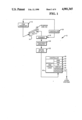
As previously stated, this invention relates to a process for searching a matrix of binary pixel data associated with a document so as to find search regions in which straight lines may be found, with the straight lines being those which are perpendicular to the original direction of scanning which produced the matrix of binary data. Once the search regionsare found, they can be used to focus the searches within the search areas to locate the long lines. In order to describe the process, it is useful to refer to FIG. 1 which shows apparatus 10 which may be used in carrying out the invention.
The apparatus 10 includes an item transport 12 which moves an item, like a document 14, towards a scanning line 16 where the document 14 is imaged bya scanner 18 as is conventionally done. The scanner 18 produces successive scan lines or columns of pixel data or pixels as the item 14 is moved in reading relationship therewith. The scanner 18 could also be a hand held scanner, for example, which is moved over a stationary document to effect the reading. From the scanner 18, the successive columns of pixel data areprocessed to minimize noise associated with the pixels and to threshold thepixels into a binary "1", for example, which may represent the presence of data and a binary "0" which may represent the absence of data. This processing is effected by conventional circuitry shown only as processing circuitry 20.
The output of the processing circuitry 20 is a matrix 22 of binary data or pixels (not compressed) which corresponds to the image of the associated document 14. The matrix 22 of binary data may include about 1700 pixels per column with a resolution of 200 pixels per inch, for example, as just one illustration of a document whose width is about 81/2 inches wide. Naturally, the overall size of the matrix 22 of data is dependent upon a particular application; however, the particular size is not important to an understanding of this invention nor to the operation thereof. The scanner 18 and the item transport 12 may be controlled by a separate controller 24, for example, or they may be controlled by the controller 26which is used to process the matrix 22 of data or pixels.
The controller 26 (FIG. 1) is a conventional controller which may be used to process the matrix 22 of pixels according to this invention. The controller 26 includes a read only memory (ROM 28), a random access memory(RAM 30), a key board (KB) 32, a display 34, interfaces 36 and 38, and interface and control logic 40 which is used to interconnect all the components shown in a conventional manner. The form of the controller 26 shown is used to simply facilitate a discussion of the operation of the controller 26; the actual form of the controller 26 is different from thatshown.
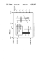
As alluded to earlier herein, when one has a matrix of binary pixels which corresponds to the image of a document, like 14, for example, it is sometimes difficult to find out where in the matrix the particular information or data sought is located. As noted earlier herein, it is difficult to find long lines which are perpendicular to the direction of scanning. For example, assume that the matrix 41 of binary pixels shown inFIG. 2 (similar to the matrix 22 of binary data shown in FIG. 1) corresponds to the image of a document 14. Assume, also, that the scanningis done along the columns as shown in FIG. 2. The entire image shown in FIG. 2 can be expressed as a number of columns of data and a number of rows of data or pixels which are either binary 1's or 0's in the example being described. For example, column 0 may start at the top right side of the document 14, as viewed in FIG. 1, while column 1,000 approaches the left side of the document 14. Correspondingly, row 0 appears at the top ofthe document 14, while row 1700 approaches the bottom of the document 14, as viewed in FIG. 1. Accordingly, the upper left hand corner of the matrix41 (FIG. 2) corresponds to the upper right hand corner of the document 14 shown in FIG. 1. Naturally, the columns and rows may be reversed, depending upon how the documents are scanned, for example.
The lines and printing shown in FIG. 2 represent the binary ones of data which comprise the matrix 41, with the binary zeros comprising the background of the document 14. It is the lines like lines 42, 44, 46, 48, and 50, for example, which are difficult to find; these are the lines which are perpendicular to the direction of scanning line 16.
The first step in the process or method according to this invention is to determine a number of search scans which will be used to search the matrix41 of binary data. These search scans will be used to search the matrix 41 in a direction which is parallel to the scanning line 16 which is also shown on FIG. 2. The binary ones found in these search scans, after some processing to be later described herein, may be indicative of the long lines being sought.
There are certain parameters which are used in the process of this invention; these are N, P, Q, and L. These parameters are described as follows:
1. "N" relates to the number of search scans which are selected to scan thematrix 41 at equal intervals thereon. In the embodiment described, N is equal to 5, with search scans #1 through #5 being shown in FIG. 2. "N" is chosen so that the spacing between successive scans is much less than the minimum length of the line to be detected. Lines like 42 and 44 are the long lines which are to be found.
2. "P" relates to the number of AND-scans which are included in a particular AND-set. In the embodiment described, the number of AND-scans included in an AND-set is two. The And-scans relate to the processing of the scans #1 through #5 (FIG. 2) as will be described hereinafter. For example, scan #1 and scan #2 in FIG. 2 are considered an AND-set. P is selected so that the AND-set spans a distance which is somewhat less than the minimum line length anticipated. There are N-P+1 AND-sets.
3. The scans in each AND-set are logically ANDed to produce a single "AND-scan" for each AND-set. For example, scan #1 and scan #2 in FIG. 2 (which comprise an AND-set) are ANDed to produce AND-scan-1 shown in FIG. 3. There are N-P+1 "AND-scans" within the embodiment described. Notice from FIG. 2 that there are four "AND-scans", namely AND-scans-#1 through #4.
4. The N-P+1 "AND-scans" are grouped into overlapping sets containing "Q" adjacent AND-scans. In the embodiment described, Q=2. In other words, AND-scan-1 and AND-scan-2 shown in FIG. 4 comprise an "OR-set". Q is chosen so that the distance spanned by the scans is somewhat longer than the maximum line length. There are N-P-Q+2 AND-scan sets in the embodimentdescribed.
5. The "AND-scans" making up an "OR-set" are logically "ORed" to produce a single "OR-scan" for each OR-set. For example, AND-scan-#1 and AND-scan-#2shown in FIG. 4 are logically ORed to generate "OR-scan-1". There are N-P-Q+2 "OR-scans" in the embodiment described.
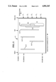
6. For each run, in each OR-scan, which is not longer than the maximum linethickness L, a search window is created which has dimensions slightly larger than L as measured in the scan direction and spanning the OR-set ina direction which is perpendicular to the scan direction. The set of these search windows is the output of this procedure. This aspect will be more clearly understood in connection with a discussion of FIG. 5.
Before describing certain additional features of this invention, and beforedescribing how certain of the parameters mentioned can be varied to suit particular applications, it appears useful to describe a particular application.
After determining the parameters for using the method of this invention as just described, the next step according to this invention is to scan a predetermined area of the matrix 41 of binary data in a direction which isparallel to the original direction of scanning (scanning line 16). In some cases, the predetermined area may be a portion of the matrix 41, or it maybe the entire area of the matrix 41. In the embodiment described, the predetermined area relates to the entire matrix 41. In the example being described, N was equal to five. In this regard, notice that there are fivesearch scan lines shown in FIG. 2, namely, search scan #1 through #5.
The search results for the search scans #1 through #5 shown in FIG. 2 are shown as scans-1 through 5, respectively, in FIG. 3. To provide some correlation, notice that binary data 42-1 shown in FIG. 3 for scan-1 corresponds to a portion of the line 42 shown in FIG. 2. Similarly, binarydata 44-1 corresponds to a portion of line 44. Notice that lines 46 and 50 are thicker than the lines 42 and 44; correspondingly, the associated binary data 46-1 and 50-1 is "wider", as measured along the search scan #1, than the data 42-1 and 44-1 associated with lines 42 and 44-1. Notice that the printing "THIS IS A BOX WITH" and the printing "TEXT THROUGH" shown in FIG. 2 lie between the search scans #1 and #2, and consequently, binary data about this printing does not show up in scan-1 and scan-2 shown in FIG. 3. Notice however, that a portion of the printing "THE EDGE"shown in FIG. 2 does lie within search scan #2; consequently, this shows upas the binary data included in the bracket 52 (FIG. 3). Notice also, that the thick line 54 shows up as binary data 54-3, 54-4 and 54-5 (FIG. 3) associated with the scans-3, 4, and -5.
The next step in the method according to this invention is to AND certain of the scans-1 through -5 shown in FIG. 3 in the following manner. In the embodiment described, the scans-1 and -2 which comprise an AND-set are ANDed together to generate the AND-scan-1 shown on line 56 in FIG. 3. Notice from FIG. 3 that the digital data 42-1-2 is the result of ANDing digital data 42-1 and 42-2. Scans-2 and -3 are similarly ANDed together togenerate AND-scan-2. Notice also, that the digital data 42-2-3 is the result of ANDing digital data 42-2 and 42-3. Scans-3 and -4 are ANDed together to generate AND-scan-3, and scans-4 and -5 are ANDed together to generate AND-scan-4. Naturally, if more than five search scans were utilized in a particular embodiment, this process would be repeated for the remaining scans to generate the remaining AND-scans. Notice that therewas also some overlapping in the ANDing operation, i.e., scan-2 is used to generate both AND-scan-1 and AND-scan-2.
The next step in the method of this invention is to "OR" the AND-scan-1 through AND-scan-4 data in the embodiment described. For example, the digital data (actually binary ls) associated with the AND-scan-1 and AND-scan-2 are ORed together to generate the "OR-scan-1" shown in FIG. 4. A function of the OR operation is to catch a long line which may be discontinuous at certain points along its length. The AND-scan-1 and the AND-scan-2 comprise an "OR set" alluded to earlier herein. AND-scan-2 and AND-scan-3 are ORed together to generate OR-scan-2, and correspondingly, AND-scan-3 and AND-scan-4 are ORed together to generate OR-scan-3. This process is repeated for additional AND-scans which may appear in a particular application to be processed. Again, there is some overlapping in the method in that the AND-scan-2 is used in the generation of OR-scan-1 and OR-scan-2.
The ANDing and ORing operations described may be carried on within the controller 26 shown in FIG. 1. Notice that the binary data 42-1-2 and 42-2-3 associated with AND-scan-1 and AND-scan-2, respectively, are combined by the ORing operation to generate the binary data 42-OR-1 which is associated with the OR-scan-1 shown in FIG. 4. OR-scan-2 and OR-scan-3 are generated in the same manner as described.
After the OR-scans-1 through -3 are generated as described, they are used to define search regions in which the controller 26 may look to find the long lines, like lines 42 and 44 for example, which are perpendicular to the direction of scanning line 16. In this regard, the controller 26 keepsa record of the row and column positions for the binary data derived from the search scans #1 through #5 as discussed in relation to FIGS. 2-4. Thismeans that the digital data 42-OR-1 (FIG. 4) is derived from the AND-scan-1and the AND-scan-2, which in turn, are derived from scan-1, scan-2 and scan-3 as previously described. The controller 26 then extends the search region associated with OR-scan-1 by extending it to cover a distance including search scans #1-#3 and a little distance on each side of search scan #1 and search scan #3 as shown by bracket 58 shown in FIG. 5. Correspondingly, OR-scan-2 extends at least over a distance including search scans #2-#4 as indicated by bracket 60. And, OR-scan-3 extends at least over the distance indicated by dashed bracket 62. The location of the binary data 42-1 from scan-1 and the location of binary data 42-5 fromscan-5 shown in FIG. 4 are used to establish the row limits for the search region 42-R shown in FIG. 5. Search region 42-R (FIG. 5) is made slightly wider than that warranted by the width of the data, like 42-1 (FIG. 3), itself, so as to provide a rectangular search region as shown to make surethat line 42 shown in FIG. 2 is included in the search region 42-R. The remaining search regions 44-R, 46-R, 48-R and 50-R shown in FIG. 5 are similarly determined, and they correspond to the long lines 44, 46, 48, and 50, respectively, shown in FIG. 2. The search regions, like 42-R, are then used to locate the long lines which are perpendicular to the scanningdirection or scanning line 16.
Notice that a search region for the wide line 54 shown in FIG. 2 is not included in FIG. 5. The digital data, like 54-OR-3 shown in FIG. 4, is toowide to be indicative of a narrow line; consequently, it is discarded by the controller 26 instead of being used by it to create a search region asdescribed. Notice, also, that squiggle or illegible scrawl 64 shown in FIG.2 and shown as 64-1 in FIG. 3 is eliminated in AND-scan-3 shown in FIG. 3.
The procedure, just described, can be adjusted for different applications by changing the various parameters discussed earlier herein. For example:
1. A large value of N, as discussed earlier herein, allows the detection ofshort lines.
2. A small value of N allows only long lines to be detected.
3. Similarly, large values of P cause only long solid lines to be detected.
4. Small values of P are useful in detecting short, broken lines.
5. Large values of Q result in long search windows for long lines or collinear short lines.
6. Small values of Q result in short search windows for short lines or parts of longer lines.
7. Large values of L will result in thick and thin lines being detected.
8. Small values of L will result in only thin lines being detected.

Claims (11)

What is claimed is:
1. A method of searching a matrix of binary data to find search regions in which straight lines may be found, with the straight lines being those which are perpendicular to the original direction of scanning which produced the matrix of binary data; said method comprising the steps:
(a) determining a number of search scans to cover a predetermined area of said matrix of binary data;
(b) scanning said predetermined area in a direction which is parallel to said original direction of scanning to search for the presence of binary ones along said predetermined number of search scans to generate search results for each of said search scans, with a binary one indicating the presence of data;
(c) ANDing the search results of preselected said search scans to generate AND-scans;
(d) ORing preselected said AND-scans to generate OR-scans; and
(e) using said OR-scans to define said search regions in which to look for said straight lines which are perpendicular to the original direction of scanning.
2. The method as claimed in claim 1 in which said determining step is effected by considering the length of the straight lines to be found.
3. The method as claimed in claim 2 in which said ANDing step is effected by ANDing adjacent said search scans.
4. The method as claimed in claim 3 in which said ORing step is effected by ORing adjacent said AND-scans.
5. The method as claimed in claim 1 in which said ANDing step is effected by ANDing at least two adjacent said search scans.
6. The method as claimed in claim 5 in which said ORing step is effected by ORing at least two adjacent said AND-scans.
7. The method as claimed in claim 6 in which said using step is effective for defining generally rectangular search regions.
8. A method of searching a matrix of binary data to find search regions in which straight lines may be found, with the straight lines being those which are perpendicular to the original direction of scanning which produced the matrix of binary data; said method comprising the steps:
(a) determining a number of search scans to cover a predetermined area of said matrix of binary data;
(b) scanning said predetermined area in a direction which is parallel to said original direction of scanning to search for the presence of binary ones along said predetermined number of search scans to produce search results, with a binary one indicating the presence of data;
(c) ANDing the search results of a first and second of said search scans to generate an AND-scan #1;
(d) ANDing the search results of said second search scan and a third of said search scans to generate an AND-scan #2;
(e) ANDing the search results of said third search scan and a fourth of said search scans to generate an AND-scan #3;
(f) repeating steps (c), (d), and (e) for the remaining search scans as exemplified in steps (c), (d), and (e) to generate remaining AND-scans;
(g) ORing AND-scan #1 and AND-scan #2 to generate OR-scan#1;
(h) ORing AND-scan #2 and AND-scan #3 to generate OR-scan #2;
(i) repeating steps (g) and (h) for the remaining AND-scans as exemplified in steps (g) and (h) to generate remaining OR-scans;
(j) using said OR-scans #1 and #2 and said remaining OR-scans to define search regions in which to look for said straight lines which are perpendicular to the original direction of scanning.
9. The method as claimed in claim 8 in which said determining step is effected by considering the length of the straight lines to be found.
10. The method as claimed in claim 9 in which said ANDing steps (c), (d), and (e) are effected upon adjacent search scans.
11. The method as claimed in claim 10 in which said ORing steps (g) and (h) are effected upon adjacent sad AND-scans.
US07/286,411 1988-12-19 1988-12-19 Method of searching binary images to find search regions in which straight lines may be found Expired - Lifetime US4901365A (en)

Priority Applications (5)

Application Number Priority Date Filing Date Title
US07/286,411 US4901365A (en) 1988-12-19 1988-12-19 Method of searching binary images to find search regions in which straight lines may be found
CA000599525A CA1316605C (en) 1988-12-19 1989-05-12 Method of searching binary images to find search regions in which straight lines may be found
JP1326216A JPH02224187A (en) 1988-12-19 1989-12-18 Searching of binary image to discover searching area for straight line
DE68913475T DE68913475T2 (en) 1988-12-19 1989-12-19 Method for searching a matrix of binary data.
EP89313265A EP0375352B1 (en) 1988-12-19 1989-12-19 Method of searching a matrix of binary data

Applications Claiming Priority (1)

Application Number Priority Date Filing Date Title
US07/286,411 US4901365A (en) 1988-12-19 1988-12-19 Method of searching binary images to find search regions in which straight lines may be found

Publications (1)

Publication Number Publication Date
US4901365A true US4901365A (en) 1990-02-13

Family

ID=23098486

Family Applications (1)

Application Number Title Priority Date Filing Date
US07/286,411 Expired - Lifetime US4901365A (en) 1988-12-19 1988-12-19 Method of searching binary images to find search regions in which straight lines may be found

Country Status (5)

Country Link
US (1) US4901365A (en)
EP (1) EP0375352B1 (en)
JP (1) JPH02224187A (en)
CA (1) CA1316605C (en)
DE (1) DE68913475T2 (en)

Cited By (12)

* Cited by examiner, † Cited by third party
Publication number Priority date Publication date Assignee Title
US5048099A (en) * 1990-05-21 1991-09-10 Eastman Kodak Company Polygon-based method for automatic extraction of selected text in a digitized document
US5048107A (en) * 1989-06-06 1991-09-10 Ricoh Company, Ltd. Table region identification method
US5058189A (en) * 1988-02-16 1991-10-15 Ricoh Company, Ltd. Apparatus and method for area designation on a document
US5075895A (en) * 1989-04-05 1991-12-24 Ricoh Company, Ltd. Method and apparatus for recognizing table area formed in binary image of document
US5165072A (en) * 1990-04-27 1992-11-17 Canon Kabushiki Kaisha Image processing apparatus which detects a line image
US5268580A (en) * 1992-09-02 1993-12-07 Ncr Corporation Bar code enhancement system and method for vision scanners
US5444793A (en) * 1993-06-15 1995-08-22 Ncr Corporation Method for detecting machine printed monetary amounts in binary images
US5524068A (en) * 1992-08-21 1996-06-04 United Parcel Service Of America, Inc. Method and apparatus for finding areas of interest in images
US20080310685A1 (en) * 2007-06-18 2008-12-18 Speigle Jon M Methods and Systems for Refining Text Segmentation Results
CN102156884A (en) * 2011-04-25 2011-08-17 中国科学院自动化研究所 Straight segment detecting and extracting method
CN104751177A (en) * 2015-03-26 2015-07-01 常州大学 Method for identifying given blurred digital straight-line segment in digital image
CN105513044A (en) * 2015-11-20 2016-04-20 常州大学 Digital straight segment recognition method based on statistical measurement of straight line features

Citations (9)

* Cited by examiner, † Cited by third party
Publication number Priority date Publication date Assignee Title
US3930237A (en) * 1974-03-07 1975-12-30 Computervision Corp Method for automating the production of engineering documentation utilizing an integrated digital data base representation of the documentation
US4044327A (en) * 1973-08-01 1977-08-23 Bunker Ramo Corporation Trimming potentiometers with coarse and fine adjustment means
US4504969A (en) * 1981-03-12 1985-03-12 Fuji Xerox Co., Ltd. Rectangular pattern recognition apparatus
US4516266A (en) * 1982-12-17 1985-05-07 International Business Machines Corporation Entity control for raster displays
US4566126A (en) * 1982-04-30 1986-01-21 Fuji Electric Company, Ltd. Pattern discriminator
US4589144A (en) * 1981-12-15 1986-05-13 Tokyo Shibaura Denki Kabushiki Kaisha Character and image processing apparatus
US4728784A (en) * 1987-01-30 1988-03-01 Federal Express Corporation Apparatus and method of encoding and decoding barcodes
US4748678A (en) * 1985-05-22 1988-05-31 Hitachi, Ltd. Method of storing and retrieving image data
US4776024A (en) * 1986-05-29 1988-10-04 International Business Machines Corporation System for segmenting character components

Family Cites Families (4)

* Cited by examiner, † Cited by third party
Publication number Priority date Publication date Assignee Title
JPS61203785A (en) * 1985-03-07 1986-09-09 Dainippon Screen Mfg Co Ltd Method and device for smoothing binary picture data
US4673987A (en) * 1985-04-22 1987-06-16 Ibm Corporation Compressed block code for facsimile transmission
US4742399A (en) * 1985-11-01 1988-05-03 Dainippon Screen Mfg. Co., Ltd. Method of and apparatus for generating high-resolution bilevel image data
US4717962A (en) * 1986-12-17 1988-01-05 Kabushiki Kaisha Toshiba Method for compressing and reconstructing a data representation of a picture

Patent Citations (9)

* Cited by examiner, † Cited by third party
Publication number Priority date Publication date Assignee Title
US4044327A (en) * 1973-08-01 1977-08-23 Bunker Ramo Corporation Trimming potentiometers with coarse and fine adjustment means
US3930237A (en) * 1974-03-07 1975-12-30 Computervision Corp Method for automating the production of engineering documentation utilizing an integrated digital data base representation of the documentation
US4504969A (en) * 1981-03-12 1985-03-12 Fuji Xerox Co., Ltd. Rectangular pattern recognition apparatus
US4589144A (en) * 1981-12-15 1986-05-13 Tokyo Shibaura Denki Kabushiki Kaisha Character and image processing apparatus
US4566126A (en) * 1982-04-30 1986-01-21 Fuji Electric Company, Ltd. Pattern discriminator
US4516266A (en) * 1982-12-17 1985-05-07 International Business Machines Corporation Entity control for raster displays
US4748678A (en) * 1985-05-22 1988-05-31 Hitachi, Ltd. Method of storing and retrieving image data
US4776024A (en) * 1986-05-29 1988-10-04 International Business Machines Corporation System for segmenting character components
US4728784A (en) * 1987-01-30 1988-03-01 Federal Express Corporation Apparatus and method of encoding and decoding barcodes

Cited By (16)

* Cited by examiner, † Cited by third party
Publication number Priority date Publication date Assignee Title
US5058189A (en) * 1988-02-16 1991-10-15 Ricoh Company, Ltd. Apparatus and method for area designation on a document
US5075895A (en) * 1989-04-05 1991-12-24 Ricoh Company, Ltd. Method and apparatus for recognizing table area formed in binary image of document
US5048107A (en) * 1989-06-06 1991-09-10 Ricoh Company, Ltd. Table region identification method
US5165072A (en) * 1990-04-27 1992-11-17 Canon Kabushiki Kaisha Image processing apparatus which detects a line image
US5048099A (en) * 1990-05-21 1991-09-10 Eastman Kodak Company Polygon-based method for automatic extraction of selected text in a digitized document
US5524068A (en) * 1992-08-21 1996-06-04 United Parcel Service Of America, Inc. Method and apparatus for finding areas of interest in images
US5268580A (en) * 1992-09-02 1993-12-07 Ncr Corporation Bar code enhancement system and method for vision scanners
US5444793A (en) * 1993-06-15 1995-08-22 Ncr Corporation Method for detecting machine printed monetary amounts in binary images
US20080310685A1 (en) * 2007-06-18 2008-12-18 Speigle Jon M Methods and Systems for Refining Text Segmentation Results
US8000535B2 (en) 2007-06-18 2011-08-16 Sharp Laboratories Of America, Inc. Methods and systems for refining text segmentation results
CN102156884A (en) * 2011-04-25 2011-08-17 中国科学院自动化研究所 Straight segment detecting and extracting method
CN102156884B (en) * 2011-04-25 2012-12-12 中国科学院自动化研究所 Straight segment detecting and extracting method
CN104751177A (en) * 2015-03-26 2015-07-01 常州大学 Method for identifying given blurred digital straight-line segment in digital image
CN104751177B (en) * 2015-03-26 2018-01-12 常州大学 A kind of method for being used in reference numbers image give fuzzy digit straightway
CN105513044A (en) * 2015-11-20 2016-04-20 常州大学 Digital straight segment recognition method based on statistical measurement of straight line features
CN105513044B (en) * 2015-11-20 2018-07-17 常州大学 A kind of digital direct straight line segments recognition method based on statistical measures linear feature

Also Published As

Publication number Publication date
DE68913475D1 (en) 1994-04-07
CA1316605C (en) 1993-04-20
DE68913475T2 (en) 1994-10-06
EP0375352B1 (en) 1994-03-02
JPH02224187A (en) 1990-09-06
EP0375352A1 (en) 1990-06-27

Similar Documents

Publication Publication Date Title
US4932065A (en) Universal character segmentation scheme for multifont OCR images
JP2986383B2 (en) Method and apparatus for correcting skew for line scan images
US6738154B1 (en) Locating the position and orientation of multiple objects with a smart platen
US5444793A (en) Method for detecting machine printed monetary amounts in binary images
US5016118A (en) Image determining method and apparatus
US4817171A (en) Pattern recognition system
US5915039A (en) Method and means for extracting fixed-pitch characters on noisy images with complex background prior to character recognition
US4901365A (en) Method of searching binary images to find search regions in which straight lines may be found
JPS63158678A (en) Inter-word space detecting method
US5553162A (en) Method for detecting ink jet or dot matrix printing
JPS62254282A (en) Method and apparatus for separating overlapped pattern
US4242734A (en) Image corner detector using Haar coefficients
EP0975146B1 (en) Locating the position and orientation of multiple objects with a smart platen
EP0702320A1 (en) Skew detection
EP0974931A1 (en) Method and apparatus for identifying a plurality of sub-images in an input image
JP3020293B2 (en) Attribute determination method
JPS6343788B2 (en)
JP2877548B2 (en) Document image attribute discrimination method
JPH07111738B2 (en) Area boundary extraction method in document
JP2812705B2 (en) Character extraction device
JPH0685186B2 (en) Photo area identification device
JPH0685557B2 (en) Image processing method
JPH0433074B2 (en)
JPH0338782A (en) Detector for density of original
JPH0944597A (en) Feature extracting method

Legal Events

Date Code Title Description
AS Assignment

Owner name: NCR CORPORATION, DAYTON, OH A CORP. OF MD

Free format text: ASSIGNMENT OF ASSIGNORS INTEREST.;ASSIGNOR:KELLAND, STEWART B.;REEL/FRAME:004986/0871

Effective date: 19881213

Owner name: NCR CORPORATION, A CORP. OF MD, OHIO

Free format text: ASSIGNMENT OF ASSIGNORS INTEREST;ASSIGNOR:KELLAND, STEWART B.;REEL/FRAME:004986/0871

Effective date: 19881213

FPAY Fee payment

Year of fee payment: 4

STCF Information on status: patent grant

Free format text: PATENTED CASE

FPAY Fee payment

Year of fee payment: 8

FPAY Fee payment

Year of fee payment: 12