US4901354A - Method for improving the reliability of voice controls of function elements and device for carrying out this method - Google Patents
Method for improving the reliability of voice controls of function elements and device for carrying out this method Download PDFInfo
- Publication number
- US4901354A US4901354A US07/279,814 US27981488A US4901354A US 4901354 A US4901354 A US 4901354A US 27981488 A US27981488 A US 27981488A US 4901354 A US4901354 A US 4901354A
- Authority
- US
- United States
- Prior art keywords
- microphone
- signals
- circuit
- voice recognition
- operating person
- Prior art date
- Legal status (The legal status is an assumption and is not a legal conclusion. Google has not performed a legal analysis and makes no representation as to the accuracy of the status listed.)
- Expired - Fee Related
Links
Images
Classifications
-
- G—PHYSICS
- G10—MUSICAL INSTRUMENTS; ACOUSTICS
- G10L—SPEECH ANALYSIS OR SYNTHESIS; SPEECH RECOGNITION; SPEECH OR VOICE PROCESSING; SPEECH OR AUDIO CODING OR DECODING
- G10L15/00—Speech recognition
Definitions
- the invention relates to recognizing voice in a noisy environment and more specifically to elements controlled by voice initiations.
- a generic method can be derived from the operation of a device known from DE-OS 36 10 797 or U.S. Pat. No. 4,625,083. This already contains a voice microphone and an ambient noise microphone the signals of which are brought into relation to one another by electric subtraction. During the subtraction, the noise components applied equally to the two microphones--particularly ambient noises--are eliminated so that the resulting residual signals can be easily comprehended as voice commands.
- the beginning of the voice signal remaining after the subtraction is intended to produce, for example, a change-over of a hand-free telephone from receiving to transmitting mode only if really required.
- DE-OS 34 01 883 the proposal is disclosed to switch a microphone to readiness to transmit by a proximity sensor which detects the approach of the head of the operating Person to the microphone for speaking.
- the present invention has the object of specifying a method by which an interpretation of pure ambient noises as the beginning of a voice command can be eliminated by using a sound which is predominantly generated during speaking and a microphone to which at least ambient noises are applied, and of suitably constructing the generic device for carrying out the method according to the invention.
- a signal generated by a direct-contact microphone is very suitable for detecting the beginning of a voice command.
- the actual voice microphone to which ambient noises are also applied, can be electrically switched on by the contact sound signal for voice signal transmission exactly at the time of the beginning of the voice command without possibility of error.
- the operating person does not need to make any deliberate hand or head movement because both microphones can be carried in suitable harnesses in accordance with a development of the device. Neither is the operator impeded in any sequences of movements, especially not if furthermore a portable transmitter is also provided which transmits the voice commands by wireless means to an appropriate receiver.
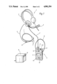
- FIG. 1 shows a diagrammatic representation of the device
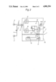
- FIG. 2 shows in a block diagram how the microphones and the trigger circuit according to the invention are connected together.
- a second microphone 5 to be directed towards the mouth of the operating person is attached to a head harness 3 which belongs to headset 4.
- a signal line 6, including an interrupting switch 6.1 to be manually operated, leads from the first microphone 2 to the head harness 3 and from there is introduced, together with a signal line of the second microphone 5, in a flexible cable 7 via amulti-pin plug-in connection 8 into a first housing part 9.1 of a housing 9.
- a trigger circuit 10 shown diagrammaticallyby a transistor symbol and explained in detail in FIG. 2, is supplied with the electric signals of the two microphones 2 and 5.
- a signal transmitter 10.3 is also indicated which can be activated by a timing section provided in the trigger circuit 10 and provides the operating person with a visual or audible signal when the maximum word reception duration of a voice recognition circuit 14 is exceeded.
- a transmitter 11 and an an electric energy source or battery 12 are arranged in a second housing part 9.2 of the housing 9.
- the transmitter 11 corresponds to a receiver 13 of the voice recognition circuit 14.
- a carrying handle or belt 15 can be advantageously attached to the second housing part 9.2.
- the trigger circuit 10 essentially consists of a threshold switch 10.1 witha reference value which can be adjusted, for example, at a potentiometer, and of a normally-open switch 10.2 which is controllable by the threshold switch 10.1.
- the switch 10.2 is in series with he signal path of the second microphone 5.
- the normally-open switch 10.2 advantageously contains a timing section T which opens the switch 10.2 after the maximum word reception duration of the voice recognition circuit 14 has elapsed and activates the signal transmitter 10.3 for the purpose mentioned.
- the transmitter 11 can operate in accordance with any principles of wireless signal transmission.
- An infrared diode is drawn in as an example.
Abstract
Description
Claims (12)
Applications Claiming Priority (2)
| Application Number | Priority Date | Filing Date | Title |
|---|---|---|---|
| DE3742929A DE3742929C1 (en) | 1987-12-18 | 1987-12-18 | Method for improving the reliability of voice controls of functional elements and device for carrying it out |
| DE3742929 | 1987-12-18 |
Publications (1)
| Publication Number | Publication Date |
|---|---|
| US4901354A true US4901354A (en) | 1990-02-13 |
Family
ID=6342902
Family Applications (1)
| Application Number | Title | Priority Date | Filing Date |
|---|---|---|---|
| US07/279,814 Expired - Fee Related US4901354A (en) | 1987-12-18 | 1988-12-05 | Method for improving the reliability of voice controls of function elements and device for carrying out this method |
Country Status (5)
| Country | Link |
|---|---|
| US (1) | US4901354A (en) |
| JP (1) | JPH01194797A (en) |
| DE (1) | DE3742929C1 (en) |
| FR (1) | FR2625020A1 (en) |
| GB (1) | GB2211336A (en) |
Cited By (28)
| Publication number | Priority date | Publication date | Assignee | Title |
|---|---|---|---|---|
| WO1992013430A1 (en) * | 1991-01-17 | 1992-08-06 | Adelman Roger A | Improved hearing apparatus |
| US5539861A (en) * | 1993-12-22 | 1996-07-23 | At&T Corp. | Speech recognition using bio-signals |
| US5539860A (en) * | 1993-12-22 | 1996-07-23 | At&T Corp. | Speech recognition using bio-signals |
| US5559926A (en) * | 1993-12-22 | 1996-09-24 | Lucent Technologies Inc. | Speech recognition training using bio-signals |
| US6072881A (en) * | 1996-07-08 | 2000-06-06 | Chiefs Voice Incorporated | Microphone noise rejection system |
| WO2001045045A1 (en) * | 1999-12-15 | 2001-06-21 | Koninklijke Philips Electronics N.V. | Speech command-controllable electronic apparatus preferably provided for co-operation with a data network |
| US6320968B1 (en) | 2000-06-28 | 2001-11-20 | Esion-Tech, Llc | Adaptive noise rejection system and method |
| US20020099541A1 (en) * | 2000-11-21 | 2002-07-25 | Burnett Gregory C. | Method and apparatus for voiced speech excitation function determination and non-acoustic assisted feature extraction |
| EP1229432A2 (en) * | 2000-12-15 | 2002-08-07 | BSH Bosch und Siemens Hausgeräte GmbH | Input device and method for inputting information in a control unit |
| US20020198705A1 (en) * | 2001-05-30 | 2002-12-26 | Burnett Gregory C. | Detecting voiced and unvoiced speech using both acoustic and nonacoustic sensors |
| US6532447B1 (en) * | 1999-06-07 | 2003-03-11 | Telefonaktiebolaget Lm Ericsson (Publ) | Apparatus and method of controlling a voice controlled operation |
| US20030128848A1 (en) * | 2001-07-12 | 2003-07-10 | Burnett Gregory C. | Method and apparatus for removing noise from electronic signals |
| US20030179888A1 (en) * | 2002-03-05 | 2003-09-25 | Burnett Gregory C. | Voice activity detection (VAD) devices and methods for use with noise suppression systems |
| WO2003083828A1 (en) * | 2002-03-27 | 2003-10-09 | Aliphcom | Nicrophone and voice activity detection (vad) configurations for use with communication systems |
| US20040133421A1 (en) * | 2000-07-19 | 2004-07-08 | Burnett Gregory C. | Voice activity detector (VAD) -based multiple-microphone acoustic noise suppression |
| US20040198462A1 (en) * | 2002-03-12 | 2004-10-07 | Ching-Chuan Lee | Handsfree structure with antibackgroung noise function |
| US20040249633A1 (en) * | 2003-01-30 | 2004-12-09 | Alexander Asseily | Acoustic vibration sensor |
| US20060013415A1 (en) * | 2004-07-15 | 2006-01-19 | Winchester Charles E | Voice activation and transmission system |
| US20070160254A1 (en) * | 2004-03-31 | 2007-07-12 | Swisscom Mobile Ag | Glasses frame comprising an integrated acoustic communication system for communication with a mobile radio appliance, and corresponding method |
| US20070233479A1 (en) * | 2002-05-30 | 2007-10-04 | Burnett Gregory C | Detecting voiced and unvoiced speech using both acoustic and nonacoustic sensors |
| US20080010071A1 (en) * | 2006-07-07 | 2008-01-10 | Michael Callahan | Neural translator |
| US20080112567A1 (en) * | 2006-11-06 | 2008-05-15 | Siegel Jeffrey M | Headset-derived real-time presence and communication systems and methods |
| US20080260169A1 (en) * | 2006-11-06 | 2008-10-23 | Plantronics, Inc. | Headset Derived Real Time Presence And Communication Systems And Methods |
| US20090252351A1 (en) * | 2008-04-02 | 2009-10-08 | Plantronics, Inc. | Voice Activity Detection With Capacitive Touch Sense |
| US8948415B1 (en) | 2009-10-26 | 2015-02-03 | Plantronics, Inc. | Mobile device with discretionary two microphone noise reduction |
| US9066186B2 (en) | 2003-01-30 | 2015-06-23 | Aliphcom | Light-based detection for acoustic applications |
| US9099094B2 (en) | 2003-03-27 | 2015-08-04 | Aliphcom | Microphone array with rear venting |
| US10225649B2 (en) | 2000-07-19 | 2019-03-05 | Gregory C. Burnett | Microphone array with rear venting |
Families Citing this family (4)
| Publication number | Priority date | Publication date | Assignee | Title |
|---|---|---|---|---|
| DE4212907A1 (en) * | 1992-04-05 | 1993-10-07 | Drescher Ruediger | Integrated system with computer and multiple sensors for speech recognition - using range of sensors including camera, skin and muscle sensors and brain current detection, and microphones to produce word recognition |
| DE19750536A1 (en) * | 1997-11-14 | 1999-05-20 | Hans J Effertz | Speech supporting device for patients with assisted breathing, e.g. quadriplegic |
| DE19943875A1 (en) * | 1999-09-14 | 2001-03-15 | Thomson Brandt Gmbh | Voice control system with a microphone array |
| JP4596688B2 (en) * | 2001-06-22 | 2010-12-08 | ナップエンタープライズ株式会社 | Earphone microphone |
Citations (7)
| Publication number | Priority date | Publication date | Assignee | Title |
|---|---|---|---|---|
| US3383466A (en) * | 1964-05-28 | 1968-05-14 | Navy Usa | Nonacoustic measures in automatic speech recognition |
| GB2003002A (en) * | 1977-08-18 | 1979-02-28 | Dassault Electronique | Telephone transmission installation between interlocutors in a noisy environment |
| US4357488A (en) * | 1980-01-04 | 1982-11-02 | California R & D Center | Voice discriminating system |
| DE3401883A1 (en) * | 1984-01-20 | 1985-07-25 | Alfred 7832 Kenzingen Schief | Microphone with a proximity sensor |
| US4581758A (en) * | 1983-11-04 | 1986-04-08 | At&T Bell Laboratories | Acoustic direction identification system |
| DE3610797A1 (en) * | 1985-04-02 | 1986-10-02 | Mobira Oy, Salo | VOICE CONTROLLED SWITCH |
| US4718096A (en) * | 1983-05-18 | 1988-01-05 | Speech Systems, Inc. | Speech recognition system |
Family Cites Families (5)
| Publication number | Priority date | Publication date | Assignee | Title |
|---|---|---|---|---|
| US3746789A (en) * | 1971-10-20 | 1973-07-17 | E Alcivar | Tissue conduction microphone utilized to activate a voice operated switch |
| JPS56122245A (en) * | 1980-02-29 | 1981-09-25 | Pilot Pen Co Ltd:The | Automatic control system for transmission or recording and transmission and reception |
| US4528687A (en) * | 1981-10-22 | 1985-07-09 | Nissan Motor Company, Limited | Spoken-instruction controlled system for an automotive vehicle |
| JPS59228434A (en) * | 1983-06-09 | 1984-12-21 | Fujitsu Ltd | Voice input control system |
| JPS61502368A (en) * | 1984-06-08 | 1986-10-16 | プレセイ オ−ストラリア プロプライアトリ リミテツド | Versatile voice detection system |
-
1987
- 1987-12-18 DE DE3742929A patent/DE3742929C1/en not_active Expired
-
1988
- 1988-12-02 JP JP63304328A patent/JPH01194797A/en active Pending
- 1988-12-05 US US07/279,814 patent/US4901354A/en not_active Expired - Fee Related
- 1988-12-16 FR FR8816636A patent/FR2625020A1/en active Pending
- 1988-12-16 GB GB8829362A patent/GB2211336A/en not_active Withdrawn
Patent Citations (8)
| Publication number | Priority date | Publication date | Assignee | Title |
|---|---|---|---|---|
| US3383466A (en) * | 1964-05-28 | 1968-05-14 | Navy Usa | Nonacoustic measures in automatic speech recognition |
| GB2003002A (en) * | 1977-08-18 | 1979-02-28 | Dassault Electronique | Telephone transmission installation between interlocutors in a noisy environment |
| US4357488A (en) * | 1980-01-04 | 1982-11-02 | California R & D Center | Voice discriminating system |
| US4718096A (en) * | 1983-05-18 | 1988-01-05 | Speech Systems, Inc. | Speech recognition system |
| US4581758A (en) * | 1983-11-04 | 1986-04-08 | At&T Bell Laboratories | Acoustic direction identification system |
| DE3401883A1 (en) * | 1984-01-20 | 1985-07-25 | Alfred 7832 Kenzingen Schief | Microphone with a proximity sensor |
| DE3610797A1 (en) * | 1985-04-02 | 1986-10-02 | Mobira Oy, Salo | VOICE CONTROLLED SWITCH |
| US4625083A (en) * | 1985-04-02 | 1986-11-25 | Poikela Timo J | Voice operated switch |
Cited By (50)
| Publication number | Priority date | Publication date | Assignee | Title |
|---|---|---|---|---|
| WO1992013430A1 (en) * | 1991-01-17 | 1992-08-06 | Adelman Roger A | Improved hearing apparatus |
| US5390254A (en) * | 1991-01-17 | 1995-02-14 | Adelman; Roger A. | Hearing apparatus |
| US6041129A (en) * | 1991-01-17 | 2000-03-21 | Adelman; Roger A. | Hearing apparatus |
| US5539861A (en) * | 1993-12-22 | 1996-07-23 | At&T Corp. | Speech recognition using bio-signals |
| US5539860A (en) * | 1993-12-22 | 1996-07-23 | At&T Corp. | Speech recognition using bio-signals |
| US5559926A (en) * | 1993-12-22 | 1996-09-24 | Lucent Technologies Inc. | Speech recognition training using bio-signals |
| US6072881A (en) * | 1996-07-08 | 2000-06-06 | Chiefs Voice Incorporated | Microphone noise rejection system |
| US6532447B1 (en) * | 1999-06-07 | 2003-03-11 | Telefonaktiebolaget Lm Ericsson (Publ) | Apparatus and method of controlling a voice controlled operation |
| WO2001045045A1 (en) * | 1999-12-15 | 2001-06-21 | Koninklijke Philips Electronics N.V. | Speech command-controllable electronic apparatus preferably provided for co-operation with a data network |
| US6320968B1 (en) | 2000-06-28 | 2001-11-20 | Esion-Tech, Llc | Adaptive noise rejection system and method |
| US6594364B2 (en) | 2000-06-28 | 2003-07-15 | Esion-Tech, Llc | Adaptive noise rejection system and method |
| US10225649B2 (en) | 2000-07-19 | 2019-03-05 | Gregory C. Burnett | Microphone array with rear venting |
| US20040133421A1 (en) * | 2000-07-19 | 2004-07-08 | Burnett Gregory C. | Voice activity detector (VAD) -based multiple-microphone acoustic noise suppression |
| US9196261B2 (en) | 2000-07-19 | 2015-11-24 | Aliphcom | Voice activity detector (VAD)—based multiple-microphone acoustic noise suppression |
| US8019091B2 (en) * | 2000-07-19 | 2011-09-13 | Aliphcom, Inc. | Voice activity detector (VAD) -based multiple-microphone acoustic noise suppression |
| US20020099541A1 (en) * | 2000-11-21 | 2002-07-25 | Burnett Gregory C. | Method and apparatus for voiced speech excitation function determination and non-acoustic assisted feature extraction |
| EP1229432A2 (en) * | 2000-12-15 | 2002-08-07 | BSH Bosch und Siemens Hausgeräte GmbH | Input device and method for inputting information in a control unit |
| EP1229432A3 (en) * | 2000-12-15 | 2006-07-12 | BSH Bosch und Siemens Hausgeräte GmbH | Input device and method for inputting information in a control unit |
| US7246058B2 (en) | 2001-05-30 | 2007-07-17 | Aliph, Inc. | Detecting voiced and unvoiced speech using both acoustic and nonacoustic sensors |
| US20020198705A1 (en) * | 2001-05-30 | 2002-12-26 | Burnett Gregory C. | Detecting voiced and unvoiced speech using both acoustic and nonacoustic sensors |
| US20030128848A1 (en) * | 2001-07-12 | 2003-07-10 | Burnett Gregory C. | Method and apparatus for removing noise from electronic signals |
| US20030179888A1 (en) * | 2002-03-05 | 2003-09-25 | Burnett Gregory C. | Voice activity detection (VAD) devices and methods for use with noise suppression systems |
| US20040198462A1 (en) * | 2002-03-12 | 2004-10-07 | Ching-Chuan Lee | Handsfree structure with antibackgroung noise function |
| US20030228023A1 (en) * | 2002-03-27 | 2003-12-11 | Burnett Gregory C. | Microphone and Voice Activity Detection (VAD) configurations for use with communication systems |
| WO2003083828A1 (en) * | 2002-03-27 | 2003-10-09 | Aliphcom | Nicrophone and voice activity detection (vad) configurations for use with communication systems |
| US8467543B2 (en) | 2002-03-27 | 2013-06-18 | Aliphcom | Microphone and voice activity detection (VAD) configurations for use with communication systems |
| US20070233479A1 (en) * | 2002-05-30 | 2007-10-04 | Burnett Gregory C | Detecting voiced and unvoiced speech using both acoustic and nonacoustic sensors |
| US7043279B2 (en) * | 2002-12-03 | 2006-05-09 | Ching-Chuan Lee | Handsfree structure with antibackground noise function |
| US7433484B2 (en) | 2003-01-30 | 2008-10-07 | Aliphcom, Inc. | Acoustic vibration sensor |
| US9066186B2 (en) | 2003-01-30 | 2015-06-23 | Aliphcom | Light-based detection for acoustic applications |
| US20040249633A1 (en) * | 2003-01-30 | 2004-12-09 | Alexander Asseily | Acoustic vibration sensor |
| US9099094B2 (en) | 2003-03-27 | 2015-08-04 | Aliphcom | Microphone array with rear venting |
| US20070160254A1 (en) * | 2004-03-31 | 2007-07-12 | Swisscom Mobile Ag | Glasses frame comprising an integrated acoustic communication system for communication with a mobile radio appliance, and corresponding method |
| US8351636B2 (en) * | 2004-03-31 | 2013-01-08 | Swisscom | Glasses frame comprising an integrated acoustic communication system for communication with a mobile radio appliance, and corresponding method |
| US20060013415A1 (en) * | 2004-07-15 | 2006-01-19 | Winchester Charles E | Voice activation and transmission system |
| US8251924B2 (en) * | 2006-07-07 | 2012-08-28 | Ambient Corporation | Neural translator |
| US9772997B2 (en) * | 2006-07-07 | 2017-09-26 | Ambient Corporation | Neural translator |
| US8949129B2 (en) * | 2006-07-07 | 2015-02-03 | Ambient Corporation | Neural translator |
| US11205054B2 (en) * | 2006-07-07 | 2021-12-21 | Michael Callahan | Neural translator |
| US20190121858A1 (en) * | 2006-07-07 | 2019-04-25 | Michael Callahan | Neural translator |
| US20080010071A1 (en) * | 2006-07-07 | 2008-01-10 | Michael Callahan | Neural translator |
| US20150213003A1 (en) * | 2006-07-07 | 2015-07-30 | Michael Callahan | Neural translator |
| US8529473B2 (en) * | 2006-07-07 | 2013-09-10 | Michael Callahan | Neural translator |
| US10162818B2 (en) * | 2006-07-07 | 2018-12-25 | Ambient Corporation | Neural translator |
| US20080260169A1 (en) * | 2006-11-06 | 2008-10-23 | Plantronics, Inc. | Headset Derived Real Time Presence And Communication Systems And Methods |
| US9591392B2 (en) | 2006-11-06 | 2017-03-07 | Plantronics, Inc. | Headset-derived real-time presence and communication systems and methods |
| US20080112567A1 (en) * | 2006-11-06 | 2008-05-15 | Siegel Jeffrey M | Headset-derived real-time presence and communication systems and methods |
| US9094764B2 (en) | 2008-04-02 | 2015-07-28 | Plantronics, Inc. | Voice activity detection with capacitive touch sense |
| US20090252351A1 (en) * | 2008-04-02 | 2009-10-08 | Plantronics, Inc. | Voice Activity Detection With Capacitive Touch Sense |
| US8948415B1 (en) | 2009-10-26 | 2015-02-03 | Plantronics, Inc. | Mobile device with discretionary two microphone noise reduction |
Also Published As
| Publication number | Publication date |
|---|---|
| GB8829362D0 (en) | 1989-02-01 |
| JPH01194797A (en) | 1989-08-04 |
| FR2625020A1 (en) | 1989-06-23 |
| DE3742929C1 (en) | 1988-09-29 |
| GB2211336A (en) | 1989-06-28 |
Similar Documents
| Publication | Publication Date | Title |
|---|---|---|
| US4901354A (en) | Method for improving the reliability of voice controls of function elements and device for carrying out this method | |
| US5832440A (en) | Trolling motor with remote-control system having both voice--command and manual modes | |
| US4812842A (en) | Device for the control of rotary printing machines | |
| US5263181A (en) | Remote transmitter for triggering a voice-operated radio | |
| JPS5894959A (en) | Control of voice-starting type machine tool | |
| EP1085500A3 (en) | Timing between commands of a voice controlled device | |
| JPS5544624A (en) | Information input/output unit | |
| JP2003080482A (en) | Robot teaching device | |
| US4679177A (en) | Underwater communication system | |
| US6574341B1 (en) | Hand-free switch device for wireless intercom | |
| JPH11184633A (en) | Pen input device | |
| US5409380A (en) | System to assist the guiding of the non-sighted | |
| JPS5850889A (en) | Wireless remote controller | |
| JP2000086155A (en) | Voice controller for working machine | |
| AU645643B2 (en) | Telephone recording device | |
| CA2045959A1 (en) | Speech recognition apparatus | |
| JPH02132499A (en) | Voice input device | |
| GB2133599A (en) | Monitoring system for divers | |
| WO1992009166A1 (en) | Telephone recording device | |
| JPH06233359A (en) | Controller | |
| JPH04167695A (en) | Remote control system | |
| JP3294286B2 (en) | Speech recognition system | |
| JPH0424694A (en) | Voice input circuit | |
| KR100341353B1 (en) | voice generation apparatus for deaf and dumb person | |
| JPH01137796A (en) | Remote control device |
Legal Events
| Date | Code | Title | Description |
|---|---|---|---|
| AS | Assignment |
Owner name: DAIMLER-BENZ AKTIENGESELLSCHAFT, STUTTGART, GERMAN Free format text: ASSIGNMENT OF ASSIGNORS INTEREST.;ASSIGNORS:GOLLMAR, KLAUS;JUNEMANN, GERHARD;REEL/FRAME:004985/0996 Effective date: 19881128 Owner name: DAIMLER-BENZ AKTIENGESELLSCHAFT, GERMANY Free format text: ASSIGNMENT OF ASSIGNORS INTEREST;ASSIGNORS:GOLLMAR, KLAUS;JUNEMANN, GERHARD;REEL/FRAME:004985/0996 Effective date: 19881128 |
|
| REMI | Maintenance fee reminder mailed | ||
| LAPS | Lapse for failure to pay maintenance fees | ||
| FP | Lapsed due to failure to pay maintenance fee |
Effective date: 19940213 |
|
| STCH | Information on status: patent discontinuation |
Free format text: PATENT EXPIRED DUE TO NONPAYMENT OF MAINTENANCE FEES UNDER 37 CFR 1.362 |