US4901341A - Method and apparatus for caller-controlled receipt and delivery of voice messages - Google Patents

Method and apparatus for caller-controlled receipt and delivery of voice messages Download PDF

Info

Publication number
US4901341A
US4901341A US07/342,480 US34248089A US4901341A US 4901341 A US4901341 A US 4901341A US 34248089 A US34248089 A US 34248089A US 4901341 A US4901341 A US 4901341A
Authority
US
United States
Prior art keywords
voice message
circuit
message facility
calling station
station
Prior art date
Legal status (The legal status is an assumption and is not a legal conclusion. Google has not performed a legal analysis and makes no representation as to the accuracy of the status listed.)
Expired - Lifetime
Application number
US07/342,480
Inventor
Howard E. Carter
Joel A. Pugh
Byron C. Pierce
Current Assignee (The listed assignees may be inaccurate. Google has not performed a legal analysis and makes no representation or warranty as to the accuracy of the list.)
Messager Partners
Original Assignee
Messager Partners
Priority date (The priority date is an assumption and is not a legal conclusion. Google has not performed a legal analysis and makes no representation as to the accuracy of the date listed.)
Filing date
Publication date
Priority claimed from US07/209,891 external-priority patent/US4825460A/en
Priority to US07/342,480 priority Critical patent/US4901341A/en
Application filed by Messager Partners filed Critical Messager Partners
Priority to US07/478,674 priority patent/US5036533A/en
Publication of US4901341A publication Critical patent/US4901341A/en
Application granted granted Critical
Priority to AU53845/90A priority patent/AU5384590A/en
Priority to EP19900304400 priority patent/EP0432866A3/en
Priority to CA002015243A priority patent/CA2015243C/en
Priority to JP2106663A priority patent/JPH0362764A/en
Priority to US08/054,853 priority patent/US5381465A/en
Priority to US08/370,055 priority patent/US5646980A/en
Priority to US08/718,144 priority patent/US5694456A/en
Priority to US08/925,968 priority patent/US5982858A/en
Anticipated expiration legal-status Critical
Expired - Lifetime legal-status Critical Current

Links

Images

Classifications

    • HELECTRICITY
    • H04ELECTRIC COMMUNICATION TECHNIQUE
    • H04MTELEPHONIC COMMUNICATION
    • H04M3/00Automatic or semi-automatic exchanges
    • H04M3/42Systems providing special services or facilities to subscribers
    • H04M3/50Centralised arrangements for answering calls; Centralised arrangements for recording messages for absent or busy subscribers ; Centralised arrangements for recording messages
    • H04M3/53Centralised arrangements for recording incoming messages, i.e. mailbox systems
    • H04M3/533Voice mail systems
    • HELECTRICITY
    • H04ELECTRIC COMMUNICATION TECHNIQUE
    • H04MTELEPHONIC COMMUNICATION
    • H04M15/00Arrangements for metering, time-control or time indication ; Metering, charging or billing arrangements for voice wireline or wireless communications, e.g. VoIP

Definitions

  • the present invention relates to voice and/or data messaging methods and systems and more particularly to a line interface unit for controlling receipt and delivery of voice and/or data messages over a telephone system having a voice or data message facility connectible to a calling station and a called station via a central office.
  • a line interface unit for caller controlled receipt and delivery of voice and/or data messages over a telephone system having a voice/data message facility, the message facility connectible to at least one calling station and a called station and normally having access prevention circuitry for preventing storage and forwarding of voice/data messages unless predetermined access codes are received and verified by the circuitry.
  • the unit comprises a switch connected to a central office and having first and second positions and wherein signals are connected directly between the calling station and the central office when the switch is in the first position.
  • the interface unit also includes circuitry for signaling the message facility and circuitry for monitoring call progress upon call initiation to the called station.
  • Microprocessor-based control circuitry sequentially responds to (a) detection of a predetermined condition at the called station upon call initiation, (b) detection of a first predetermined code from the calling station indicating that the caller desires to leave a voice/data message for the called station, and (c) detection of a second predetermined code from the voice message facility, to thereby control the switch to establish a connection between the calling station and the message facility. Thereafter, the control circuitry generates a special data string to the message facility which, upon receipt thereby, facilitates barrierless entry in and out of the message facility without the predetermined access codes.
  • FIG. 1 is a block diagram of a multiple user station telephone system having a central office and a voice message facility;
  • FIG. 2 is a detailed flowchart diagram of a call routine of a voice message storage/forward method for use in a paystation system to determine whether a call can be completed from a calling station to a called station;
  • FIG. 3 is a detailed flowchart diagram of a call default routine of FIG. 2 for determining whether a caller desires to leave a voice message to be forwarded to the called station;
  • FIG. 4 is a detailed flowchart diagram of a call message routine of FIG. 3 for storing the voice message to be forwarded to the called station;
  • FIG. 5 is a simplified block diagram of a line interface unit according to the present invention.
  • FIG. 6 is a detailed schematic diagram of the first and second switch means of FIG. 5;
  • FIG. 7 is a flowchart diagram of a method for controlling receipt and delivery of voice messages according to the invention.
  • FIG. 1 is a block diagram of a multiple user station telephone system 10 inwhich a voice message storage and forwarding method has been implemented according to the teachings of U.S. Pat. No. 4,766,704 assigned to the assignee of the present application.
  • System 10 includes a plurality of user stations 12a-12n connected to a privately conventional or private owned central office 14.
  • Each of the user stations 12a-12n is preferably a "pre-pay" paystation and thus includes a suitable microprocessor and associated memory device (e.g., a programmable read only memory or "PROM”)for storing computer programs which control the operation of the paystation.
  • Each paystation also includes a conventional handset 15 as well as other standard components (not shown) normally associated with thecoin collection process.
  • a caller To initiate a call from one of the paystations 12a-12n, a caller removes the handset 15 and enters a called number. This number identifies a calledstation 16 which may be either a local or a long distance station.
  • the multiple paystation system 10 includes a voice messagefacility 18 connected to the central office 14 for recording voice messagesfrom the user stations 12a-12n. Voice message facility 18 has a plurality of access ports 19 from which recorded voice messages are output.
  • the system 10 may also include a call accounting unit 20 connected to the voice message facility 18 for the purposes to be described.
  • each calling station 12a-12n is preferably a "pre-pay" paystation which requires receipt of appropriatecoinage before a call can be placed.
  • an inquiry is made to determine whether a coin has been received. If not, the method continues at step 105 to request that the caller deposit the appropriate coinage for the call. Upon receipt of the coinage, the method continues atstep 106 to deliver the coin to a conventional coin escrow chamber of the calling station.
  • the method receives and stores the called number identifying the called station 16.
  • the called number is transmitted over the trunk and the calling station waits for an answer detection (i.e., thecalled station goes off-hook).
  • the method continues at step 112, where an inquiry is made to determine whether the call can be completed. In particular, step 112 preferably determines whether answer detection occurswithin a predetermined number of rings or whether the called station is busy. If the call can be completed, the method continues at step 114 to release the coin from the coin escrow chamber into the coin vault of the calling station. At step 116, the call is completed in a normal fashion.
  • the method initiates a "call default" routine 118 for determining whether the caller at the calling station desires to leave a voice message to be delivered to the called station.
  • the routine begins at step 120 wherein the calling station issues a prompt to the caller such as "Please Wait” or "One Moment Please”. A bilingual prompt may also be issued at step 120 if desired.
  • the handset of the calling station is disabled.
  • the call default routine 118 continues at step 124 wherein the original call is disconnected from the trunk and a "speed-dial" is initiated to the voice message facility 18.
  • the muting of the handset at step 122 is advantageous because step 124 disconnects the original call from the trunk. If the handset were not muted, the caller would otherwise hear a dialtone and the voice message facility 18 could be accessed via a "black box” or other illegal means.
  • the call default routine 118 continues at step 126 with the handset of the calling station reactivated upon receipt of a predetermined signal, e.g., a DTMF (dual tone multifrequency) signal identifying the "#" key, from thevoice message facility.
  • a predetermined signal e.g., a DTMF (dual tone multifrequency) signal identifying the "#" key
  • the voice message center issues a prompt to the caller and waits for an appropriate response.
  • the following prompt is issued at step 128:
  • the call default routine 118 continues at step 130 to determine whether thecaller desires to leave a voice message for the called station. In operation, step 130 waits for reception of a DTMF signal identifying the "#" key within a set period of time, e.g., 15-20 seconds. If the timer at step 130 times out (indicating that the caller does not wish to leave a voice message) the call default routine 118 continues at step 132 with thevoice message facility 18 sending a "disable" signal to the calling station. At step 134 in the paystation embodiment, the coin located in thecoin escrow chamber is released to a coin return chute of the calling station and the call is terminated. If the result of the inquiry 130 is positive, the method continues by calling a "call message" routine 136 forstoring the voice message to be delivered to the called station.
  • a "call message" routine 136 forstoring the voice message to be delivered to the called station.
  • the routine begins at step 138 wherein, in the paystation embodiment, the calling station releases the coin from the coin escrow chamber into the coin vault of the calling station.
  • the calling station transmits the called number to the voice message facility 18.
  • the call message routine 136 continues at step 142 wherein the calling station transmits a preferably four digit security code "YXXX"to ensure that the calling station is entitled to transmit messages to the voice message facility.
  • the first digit "Y" of the security code is a DTMF combination of a dialtone and the "#" key.
  • the remaining three digits "XXX" of the security code are preferably a number which uniquely identifies the calling station.
  • the received security code is evaluated to determine whether the calling station is entitled to transmit messages to the voice message facility 18. If the calling station is invalid, the call message routine 136 issues a disconnect signal to the calling station at step 146, therebydisconnecting the calling station from the voice message facility 18. If the result of the inquiry 144 indicates that the calling station is valid,the voice message facility 18 issues a prompt at step 148 to request that the caller begin the message.
  • the prompt at step 148 may state:
  • an inquiry is made to determine whether the caller has begun recording the message within a predetermined time, e.g., 5 seconds. If thecaller has not begun recording the message within the predetermined time, the call message routine 136 issues a salutation and then generates a disconnect signal at step 146.
  • a predetermined time e.g. 5 seconds.
  • the voice message facility 18 records the spoken message at step 152.
  • the call message routine 136 time-stamps the message and stores the message and thecalled number transmitted at step 140 in a call queue.
  • time-stamps means that the message and the called number are placed in the call queue (i.e., a suitable memory device of the voice message center) at an address uniquely associated with the time that the caller began recording the message.
  • an index "N" for the message is initialized. The index "N" represents a number of outdial attempts to be performed by the voice message center 18 as will be described.
  • the call message routine 136 terminates at step 158 by calling an "outdial-to-completion" routine which is used to attempt delivery of the stored voice message to the called station.
  • the outdial to completion routine attempts to forward each stored message at a predetermined time interval (and multiples thereof) from the time themessage is stored in the call queue.
  • the message may be forwarded redundantly to insure delivery to the calling party.
  • the message is forwarded once after a short time delay (e.g., 2-3 seconds) to insure that the calling party is attentive prior to delivery.
  • a line interface unit 200 is shown for providing enhanced control of receipt and delivery of voice messages over a telephone system having a voice message facility 18 connectible to at least one calling station 12 and a called station 16 via a central office 14.
  • the line interface unit 200 advantageously provides certain call default and message prompting operations in a standalone unit both externally to the calling station 12 and the voice message facility 18.
  • the interface unit may be located adjacent to the calling station or on the input side of the central office switching equipment.
  • the line interface unit 200 comprises a plurality of functional modules including first, second and third switches 202, 204 and 206, respectively, DTMF detector circuits 208a and 208b, a speech circuit 210, a speed-dial circuit 212, a coin detect circuit 214, a call progress detector circuit 216, a control circuit 218, a calling station monitor circuit 224 and a central office monitor circuit 226.
  • the control circuit 218 is preferably a microprocessor-based controller having suitable control programs for effecting the operations described below.
  • the control circuit 218 is connected to control the first, second and third switches 202, 204 and 206, as well as the speech circuit 210 and the speed-dial circuit 212.
  • Thespeech circuit 210, the speed-dial circuit 212 and/or the control circuit 218 may be shared by a plurality of line interface units each having the disclosed switching and monitoring components.
  • each of the first and second switches are a double-pole, double-throw switch located in the tip and ring lines 220 and 222 between the calling station 12 and the central office 14.
  • the first switch 202 is connected to the callingstation 12 in the tip and ring lines 220 and 222 and the second switch 204 is connected to the central office 14 in the tip and ring lines.
  • Each of the switches 202 and 204 have first and second positions such that signalson the tip and ring lines 220 and 222 are connected directly between the calling station 12 and the central office 14 when each of these switches are in the first position. The unit is thus "idle" when the switch contacts of the first and second switches 202 and 204 are in their first position.
  • the line interface unit 200 communicates directly with the calling station 12 when the first switch 202 is switched from its first position to its second position. Likewise, the line interface unit communicates directly with the central office 14 when the second switch 204 is switched from its first position to its second position. The unit 200 thus communicates with both the calling station 12 and the central office 14 when the switch contacts of switches 202 and 204 are activated to the second positions. When both switches are in their second position, a small amount of crosstalk between the switches 202 and 204 exists and isadvantageously used by the interface unit 200 for the purposes described below.
  • the line interface unit 200 also includes the speech circuit 210 for issuing one o more predetermined (English or bilingual) prompts to the caller at the calling station 12.
  • the speech circuit is controlled by the control circuit 218 to issue a prompt to determine whether the caller at the calling station desires to leave a voice message for a called station. If the caller desires to leave a voicemessage, the control circuit 218 operates to control the speed-dial circuit212 for speed dialing the voice message facility 18. The control of this operation is effected through sensing of various signals by the line monitor circuits 224 and 226.
  • the calling station monitor 224 is connected across the tip and ring lines 220 and 222 adjacent the calling station side of the unit 200.
  • the central office monitor circuit 226 is connected across the tip and ring lines adjacent to the central office side of the interface unit 200.
  • the calling station monitor 224 monitors the tip and ring lines for coin detect signals (which are processed by the coin detectcircuit 214) or receipt of a predetermined DTMF signal (e.g., a "#" key) from the calling station (which is processed by the DTMF detector circuit 208a).
  • the central office station monitor 226 monitors the tip and ring lines for detecting a predetermined condition at the called station (e.g.,a busy/no answer condition) upon call initiation to the called station.
  • Central office monitor circuit 226 also monitors the tip and ring lines for detecting receipt of standard or non standard DTMF signaling which is then processed by the DTMF detected circuit 208b.
  • the control circuit 218 includes a switch 219 for selectively switching the outputs of the DTMF detector circuits 208a and 208b to the control circuit 218.
  • the DTMF detector circuit 208a senses receipt (over the calling station monitor 224) of standard DTMF signal indicating that the caller at the calling station desires to leave a voice message for the called station.
  • the caller can deposit additional coinage or pull a credit card through a cardreader to indicate his/her intention to record a voice message.
  • the DTMF detectorcircuit 208b senses receipt (over the central office monitor 226) of a non standard DTMF signal from the voice message facility following the speed dialing thereto as will be described in more detail below.
  • the third switch 206 of the line interface unit is connected between the ring line 222 and ground for the purpose of generating a ground start after the speed dial circuit 212 has speed-dialed the voice message facility. This ground start is required to enable the interface unit 200 to complete a connection to the voice message facility 18 through the central office without the caller having to deposit additional coinage in the paystation.
  • the line interface unit 200 includes the coin detect circuit 214 for detecting receipt of coinage in the paystation.
  • Coin detect circuit 214 is preferably coupled to the control circuit 218 to provide a running total of all coins deposited in the calling station over a predetermined time.
  • control circuit 218 can be remotely reprogrammed (e.g., to change the prompt, the language of the prompt, the calling station identification or the number of unanswered rings at the called station which will initiate a call default) through DTMF signaling from a host or handset.
  • the second switch 204 is switched to its second position and the parameter information is down loaded to the microprocessor.
  • the control circuit 218 responds to a busy/no answer condition at the called station (following call initiation thereto) for switching the first switch 202 from its first position to its second position. This operation disconnects the calling station handset from the central office and connects the speech circuit 210 to the calling station 12 for issuing the prompt to determine if the caller desires to leave a voice message.
  • the calling station monitor circuit 224 waits for receipt of the DTMF signal from the calling station (or, alternatively, waits for receipt of additional coinage). If no DTMF signal is received (i.e., if the caller does not desire to leave a voice message), the unit 200 remains idle.
  • the control circuit 218 responds by switching the second switch 204 from its first position to itssecond position. This switching reorders dialtone and connects the speed-dial circuit 212 to the central office 14 for dialing the voice message facility 18.
  • the central office monitor circuit 226 then waits forreceipt of the DTMF signal from the voice message facility.
  • the control circuit 218 then responds to detection of the DTMF signal by the DTMF detector circuit 208b for effecting a "handshake" to the voice message facility and then switching the first and second switches 202 and 204 fromtheir respective second positions back to their respective first positions to thereby connect the calling station 12 to the voice message facility 18.
  • the line interface unit 200 when the calling station 12 is a paystation, the line interface unit 200 must present a ground start to the central office 14 inorder to dial the voice message facility 18 without additional coinage.
  • the control circuit 218 operates to activate the third switch 206 connected between the ring line 222 and ground for generating a groundstart after the voice message facility 18 has been dialed by the speed-dialcircuit 212.
  • This ground start is typically performed immediately after thelast digit of the voice message facility is dialed by the speed dial circuit and enables the interface unit to complete a connection to the message facility without the caller having to deposit additional coinage.
  • control circuit 218 is responsive to receipt of the preferably non standard DTMF signal from the voice message facility18 for switching the first and second switches from their respective secondpositions back to their respective first positions. This operation connectsthe calling paystation to the voice message facility.
  • non standard DTMF signaling increases security of the transmissions between the calling station and the voice message facility.
  • thecontrol circuit 218 switches the second switch 204 to its second position to reorder dialtone from the central office 14. Thereafter, the first switch 202 is switched back to its first position. After the central office monitor circuit 226 senses dialtone, the control circuit 218 switches the second switch back to its first position. To the central office 14 this operation emulates the calling station going off hook and then on hook. The central office 14 thus again issues a "coin return" signal; however, this signal is not passed through the "idle" line interface unit to the calling station. The caller's original coinage is then returned.
  • the line interface unit provides a so-called "voice over" operation wherein the caller at the calling station 12 is allowed to continue to monitor the call progress (i.e., the ringing on theline) while being prompted to leave a message.
  • the control circuit 218 is responsive to a predetermined condition at the called station (e.g., three (3) rings with no answer) for switching the first and second switches from their respective first positions to their respective second positions. This operation connects the speech circuit 210 to the calling station 12 for issuing the prompt while simultaneously enabling the caller at the calling station to continue to monitor the progress of the call. This operation is effected by the crosstalk between the first and second switch transformers as best seen in FIG.
  • first switch 202 includes a control relay 236 controlled by the control circuit 218 for switching the switch between the sets 240a and 240b of switch contacts.
  • the speech circuit 210 is coupled to the calling station via the line transformer 242.
  • the second switch is in its second position (across contacts 240d)
  • the speed-dial circuit 212 is coupled to the central office and thus the voice message facility via the line transformer 244.
  • Crosstalk between the line transformers 242 and 244 enables the voice over operation to be effected.
  • the control circuit 218 is responsive to receipt of a DTMF signal from the calling station 12 for switching the second switch from its second position to itsfirst position and then back to its second position. This operation reorders dialtone to the interface unit 200 and then connects the speed-dial circuit 212 to the central office for dialing the voice messagefacility 18.
  • the control circuit is responsive to receipt of the DTMF signal from the voice message facility for switching the first and second switches from their respectivesecond positions back to their respective first positions and thereby connect the calling station to the voice message facility.
  • the line interface unit 200 performs a "handshake" with the voice message facility 18.
  • the control circuit 218 transmits a predetermined data string to the voice message facility 18.
  • This data string may have the following format--"#", "#”, (10-digit number of calling station, "#", (1-digit activity code), "#", (called station number), "#"--.
  • the data string may also include a credit card number or other billing information.
  • the "#" sign delimits the fields of the data string.
  • the activity code informs the voice message facility 18 or other host that an alternative prompt has been made (e.g., a bilingual prompt).
  • the activity code is a special code indicating that connection is required to an alternate voice message facility, that the calling station includes a facsimile apparatus, that certain coinage has been deposited or that certain keypad signals have been received indicating acceptance of the service.
  • One or more of the "#" signs at the beginning of the data string described above may alternatively be non-standard DTMF signaling (such as an "A") for increased security.
  • the voice message facility When the voice message facility receives the data string, it transmits an "acknowledge” signal (e.g. an "*”) back to the unit or requests retransmission if the data has not been received.
  • the control circuit 218 switches the first and second switches back to their respective first positions.
  • the voice message facility may include access prevention circuitry and/or algorithms to prevent receipt and/or forwarding of voice messages unless predetermined access codes are presented to the system.
  • the data string from the interface unit 200 should then include a predetermined "key” that "unlocks” the voice message facility's access prevention circuits and algorithms.
  • the "key” provided to unlock the voice message facility is preferably partof the data string transmitted to the facility during the handshake process.
  • the "key” comprises three elements: the number of the calling station or "ANI", a predetermined number of digits representing the destination number, and some billing information for use in billing the user of the calling station for the caller-controlled message delivery service.
  • the access prevention circuitry of the voice message facility is then pre programmed to search for a data string with these components.
  • the actual destination number is not relevant as long as the data string includes the proper number of digits for this number. If a data string received by the message center does not include these components in the required predetermined order and/or without the proper number of expected digits, no acknowledge signalis returned to the interface unit and the unit is disconnected from the message center. If the data string includes the proper "key,” however, thevoice message facility becomes "barrierless" to the voice message subsequently transmitted from the calling station. The stored voice message can then be subsequently forwarded without input of the access codes normally required by the voice-mail system.
  • the line interface unit 200 is adapted for use with a single calling station, a plurality of calling stations maybe selectively switched to a single interface unit.
  • the control circuit 218 may include appropriate circuitry for processing FSK signaling if desired.
  • the control circuit 218 of the line interface unit 200 may alternatively include appropriate software to perform automatic numberidentification ("ANI") following the caller's affirmative decision to leavea voice message. This ANI function is advantageous when the calling stationand the called station are intralata.
  • FIG. 7 a flowchart is shown of a method for controlling receipt of voice messages according to the present invention.
  • the method uses the line interface unit 200 as described above as well as the voice message facility 18, which normally includes access prevention circuitry 19 (as shown in FIG. 5) for preventing storage of voice messagesunless predetermined access codes are received and verified by the access prevention circuitry.
  • the method begins at step 250 when a call is initiated to the called station.
  • a test is made to determine, using the monitor and detector circuits of the line interface unit, whether a predetermined condition (e.g., busy/no answer or ring/no answer) exists at the called station. If the predetermined condition exists (i.e., if the call cannot be completed), the method continues at step 254 by connecting the speech circuit 210 to the calling station to thereby enable the speech circuit toissue the prompt.
  • the speech circuit is activated, under the control of the control circuit 218, to issue the prompt to the caller at the calling station.
  • a test 258 is then made to determine, using the monitor and detector circuits, whether a predetermined code has been received from the calling station indicating that the caller desires to leave a voice message for the called station. If the predetermined code has been received from the calling station, the method continues at step 260 to connect the signaling circuit 212 to the central office to thereby enable the signaling circuit to signal the voice message facility. At step262, the signaling circuit is activated, under the control of the control circuit, to signal the voice message facility. Thereafter, at step 264, a test is made to determine, using the monitor and detector circuits, whether a predetermined code has been received from the voice message facility.
  • the method continues at step 266 to transmit a predetermined data string from the line interface unit to the voice message facility.
  • the predetermined data string including information that, once recognized by the access prevention circuitry 19 means of the voice message facility, enables the voice message to be stored and forwarded from the voice message facility withoutentry of the predetermined access codes normally required by the access prevention circuitry.

Abstract

A line interface unit for caller-controlled receipt and delivery of voice and/or data meassages over a telephone system having a voice/data message facility, the message facility connectible to at least one calling station and a called station and normally having access prevention circuitry for preventing storage and forwarding of voice/data messages unless predetermined access codes are received and verified by the circuitry. In the preferred embodiment, the unit comprises a switch connected to a central office and having first and second positions and wherein signals are connected directly between the calling station and the central office when the switch is in the first position. The interface unit also includes circuitry for signaling the message facility and circuitry for monitoring call progress upon call initiation to the called station. Microprocessor-based control circuitry responds to detection of a predetermined condition at the called station upon call initiation, to detection of a first predetermined code from the calling station indicating that the caller desires to leave a voice/data message for the called station, and to detection of a second predetermined code from the voice message facility, to establish a connection between the calling station and the message facility. Thereafter, a special data string is transmitted to the message facility which, upon receipt thereby, facilitates barrierless entry in and out of the message facility without the predetermined access codes.

Description

This application is a continuation-in-part of prior co-pending application No. 07/209,891, filed Jun. 22, 1988 now U.S. Pat. No. 4,825,460.
TECHNICAL FIELD
The present invention relates to voice and/or data messaging methods and systems and more particularly to a line interface unit for controlling receipt and delivery of voice and/or data messages over a telephone system having a voice or data message facility connectible to a calling station and a called station via a central office.
BACKGROUND OF THE INVENTION
It is known in the art to operate a multiple paystation telephone installation from a central office. In such systems, the central office typically performs the coin collect, return and verification functions necessary to provide both local and long distance services. Multiple paystation installations of the type described above have recently been enhanced through the use of so called "smart" paystations. Such paystations typically include their own microprocessor and associated memory for supporting various computer programs. These programs provide several desirable operating features, e.g., loop start dialtone and "least cost routing" for long distance telephone calls. Although "smart" paystations are advantageous, such devices have yet to be successfully integrated into voice messaging systems. Paystation operators have therefore been unable to offer message storage/forwarding to users of their paystations.
It would therefore be desirable to provide a line interface unit for use in controlling receipt and delivery of voice and/or data messages in a telephone system which overcomes these and other problems of the prior art and which facilitates the providing of certain call-default and message prompting operations in a stand-alone unit.
BRIEF SUMMARY OF THE INVENTION
In one embodiment of the invention, a line interface unit is described for caller controlled receipt and delivery of voice and/or data messages over a telephone system having a voice/data message facility, the message facility connectible to at least one calling station and a called station and normally having access prevention circuitry for preventing storage and forwarding of voice/data messages unless predetermined access codes are received and verified by the circuitry. In the preferred embodiment, the unit comprises a switch connected to a central office and having first and second positions and wherein signals are connected directly between the calling station and the central office when the switch is in the first position. The interface unit also includes circuitry for signaling the message facility and circuitry for monitoring call progress upon call initiation to the called station. Microprocessor-based control circuitry sequentially responds to (a) detection of a predetermined condition at the called station upon call initiation, (b) detection of a first predetermined code from the calling station indicating that the caller desires to leave a voice/data message for the called station, and (c) detection of a second predetermined code from the voice message facility, to thereby control the switch to establish a connection between the calling station and the message facility. Thereafter, the control circuitry generates a special data string to the message facility which, upon receipt thereby, facilitates barrierless entry in and out of the message facility without the predetermined access codes.
BRIEF DESCRIPTION OF THE DRAWINGS
For a more completed understanding of the present invention and the advantages thereof, reference is now made to the following Description taken in conjunction with the accompanying Drawings in which:
FIG. 1 is a block diagram of a multiple user station telephone system having a central office and a voice message facility;
FIG. 2 is a detailed flowchart diagram of a call routine of a voice message storage/forward method for use in a paystation system to determine whether a call can be completed from a calling station to a called station;
FIG. 3 is a detailed flowchart diagram of a call default routine of FIG. 2 for determining whether a caller desires to leave a voice message to be forwarded to the called station;
FIG. 4 is a detailed flowchart diagram of a call message routine of FIG. 3 for storing the voice message to be forwarded to the called station;
FIG. 5 is a simplified block diagram of a line interface unit according to the present invention;
FIG. 6 is a detailed schematic diagram of the first and second switch means of FIG. 5;
FIG. 7 is a flowchart diagram of a method for controlling receipt and delivery of voice messages according to the invention.
DETAILED DESCRIPTION
FIG. 1 is a block diagram of a multiple user station telephone system 10 inwhich a voice message storage and forwarding method has been implemented according to the teachings of U.S. Pat. No. 4,766,704 assigned to the assignee of the present application. System 10 includes a plurality of user stations 12a-12n connected to a privately conventional or private owned central office 14. Each of the user stations 12a-12n is preferably a "pre-pay" paystation and thus includes a suitable microprocessor and associated memory device (e.g., a programmable read only memory or "PROM")for storing computer programs which control the operation of the paystation. Each paystation also includes a conventional handset 15 as well as other standard components (not shown) normally associated with thecoin collection process.
To initiate a call from one of the paystations 12a-12n, a caller removes the handset 15 and enters a called number. This number identifies a calledstation 16 which may be either a local or a long distance station. As also seen in FIG. 1, the multiple paystation system 10 includes a voice messagefacility 18 connected to the central office 14 for recording voice messagesfrom the user stations 12a-12n. Voice message facility 18 has a plurality of access ports 19 from which recorded voice messages are output. The system 10 may also include a call accounting unit 20 connected to the voice message facility 18 for the purposes to be described.
Multiple user station systems such as shown in FIG. 1 as well as other telephone systems having non-pay calling stations have been enhanced by the method for receiving the delivering voice messages described in U.S. Pat. No. 4,766,604. The method exploits the inability of a calling station12a-12n to complete a call to the called station 16 to automatically cause the called station to default to the voice message facility 18. If the caller desires to leave a voice message to be delivered to the called station 16, the caller is thereafter prompted to store the voice message. The voice message facility 18 then initiates an outdial routine which makes a predetermined number of attempts to forward the voice message to the called station. Each of these attempts are typically made at a predetermined time interval programmed by the system operator.
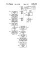
Referring now to FIG. 2, a flowchart diagram is shown detailing a call routine 100 of the method for receiving and delivering voice messages in apaystation embodiment as described in U.S. Pat. No. 4,766,604. The call routine 100 begins at step 102 when the calling station handset 15 goes off-hook. As described in that application, each calling station 12a-12n is preferably a "pre-pay" paystation which requires receipt of appropriatecoinage before a call can be placed. Accordingly, at step 104, an inquiry is made to determine whether a coin has been received. If not, the method continues at step 105 to request that the caller deposit the appropriate coinage for the call. Upon receipt of the coinage, the method continues atstep 106 to deliver the coin to a conventional coin escrow chamber of the calling station.
At step 108, the method receives and stores the called number identifying the called station 16. At step 110, the called number is transmitted over the trunk and the calling station waits for an answer detection (i.e., thecalled station goes off-hook). The method continues at step 112, where an inquiry is made to determine whether the call can be completed. In particular, step 112 preferably determines whether answer detection occurswithin a predetermined number of rings or whether the called station is busy. If the call can be completed, the method continues at step 114 to release the coin from the coin escrow chamber into the coin vault of the calling station. At step 116, the call is completed in a normal fashion. If the result of the inquiry at step 112 indicates that answer detection has not occurred (i.e., the called station remains on-hook) within the predetermined number of rings following call initiation or that the calledstation is busy, the method initiates a "call default" routine 118 for determining whether the caller at the calling station desires to leave a voice message to be delivered to the called station.
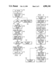
Referring now to FIG. 3, a detailed flowchart diagram is shown of the call default routine 118 of FIG. 2. The routine begins at step 120 wherein the calling station issues a prompt to the caller such as "Please Wait" or "One Moment Please". A bilingual prompt may also be issued at step 120 if desired. At step 122, the handset of the calling station is disabled. The call default routine 118 continues at step 124 wherein the original call is disconnected from the trunk and a "speed-dial" is initiated to the voice message facility 18. The muting of the handset at step 122 is advantageous because step 124 disconnects the original call from the trunk. If the handset were not muted, the caller would otherwise hear a dialtone and the voice message facility 18 could be accessed via a "black box" or other illegal means.
The call default routine 118 continues at step 126 with the handset of the calling station reactivated upon receipt of a predetermined signal, e.g., a DTMF (dual tone multifrequency) signal identifying the "#" key, from thevoice message facility. At step 128, the voice message center issues a prompt to the caller and waits for an appropriate response. Although not meant to be limiting, the following prompt is issued at step 128:
"This is a voice message center. Your party is not available at this time. If you would like to leave a 20 second message at no additional charge, press the "#" key and I will attempt to deliver your message every 15 minutes for the next two hours. If you do not wish to leave a message, hang up, and I will return your money."
The call default routine 118 continues at step 130 to determine whether thecaller desires to leave a voice message for the called station. In operation, step 130 waits for reception of a DTMF signal identifying the "#" key within a set period of time, e.g., 15-20 seconds. If the timer at step 130 times out (indicating that the caller does not wish to leave a voice message) the call default routine 118 continues at step 132 with thevoice message facility 18 sending a "disable" signal to the calling station. At step 134 in the paystation embodiment, the coin located in thecoin escrow chamber is released to a coin return chute of the calling station and the call is terminated. If the result of the inquiry 130 is positive, the method continues by calling a "call message" routine 136 forstoring the voice message to be delivered to the called station.
Referring now to FIG. 4, a detailed flowchart diagram is shown of the call message routine 136 of FIG. 3. The routine begins at step 138 wherein, in the paystation embodiment, the calling station releases the coin from the coin escrow chamber into the coin vault of the calling station. At step 140, the calling station transmits the called number to the voice message facility 18. The call message routine 136 continues at step 142 wherein the calling station transmits a preferably four digit security code "YXXX"to ensure that the calling station is entitled to transmit messages to the voice message facility. Preferably, the first digit "Y" of the security code is a DTMF combination of a dialtone and the "#" key. The remaining three digits "XXX" of the security code are preferably a number which uniquely identifies the calling station.
At step 144, the received security code is evaluated to determine whether the calling station is entitled to transmit messages to the voice message facility 18. If the calling station is invalid, the call message routine 136 issues a disconnect signal to the calling station at step 146, therebydisconnecting the calling station from the voice message facility 18. If the result of the inquiry 144 indicates that the calling station is valid,the voice message facility 18 issues a prompt at step 148 to request that the caller begin the message. For example, the prompt at step 148 may state:
"Please state your name and your 20 second message now."
At step 150, an inquiry is made to determine whether the caller has begun recording the message within a predetermined time, e.g., 5 seconds. If thecaller has not begun recording the message within the predetermined time, the call message routine 136 issues a salutation and then generates a disconnect signal at step 146.
If the result of the inquiry at step 150 is positive, the voice message facility 18 records the spoken message at step 152. At step 154, the call message routine 136 time-stamps the message and stores the message and thecalled number transmitted at step 140 in a call queue. As used herein, the phrase "time-stamps" means that the message and the called number are placed in the call queue (i.e., a suitable memory device of the voice message center) at an address uniquely associated with the time that the caller began recording the message. At step 156, an index "N" for the message is initialized. The index "N" represents a number of outdial attempts to be performed by the voice message center 18 as will be described. The call message routine 136 terminates at step 158 by calling an "outdial-to-completion" routine which is used to attempt delivery of the stored voice message to the called station.
The outdial to completion routine attempts to forward each stored message at a predetermined time interval (and multiples thereof) from the time themessage is stored in the call queue. The message may be forwarded redundantly to insure delivery to the calling party. Alternatively, the message is forwarded once after a short time delay (e.g., 2-3 seconds) to insure that the calling party is attentive prior to delivery.
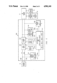
While the invention described in U.S. Pat. No. 4,766,604 has proven satisfactory, it has been found desirable to provide certain enhancements and improvements to the voice messaging method described therein. Referring now to FIG. 5, a line interface unit 200 is shown for providing enhanced control of receipt and delivery of voice messages over a telephone system having a voice message facility 18 connectible to at least one calling station 12 and a called station 16 via a central office 14. As will be described, the line interface unit 200 advantageously provides certain call default and message prompting operations in a standalone unit both externally to the calling station 12 and the voice message facility 18. The interface unit may be located adjacent to the calling station or on the input side of the central office switching equipment.
As seen in FIG. 5, and as more particularly described in U.S. Pat. No. 4,825,460 assigned to the assignee of the present invention, the line interface unit 200 comprises a plurality of functional modules including first, second and third switches 202, 204 and 206, respectively, DTMF detector circuits 208a and 208b, a speech circuit 210, a speed-dial circuit 212, a coin detect circuit 214, a call progress detector circuit 216, a control circuit 218, a calling station monitor circuit 224 and a central office monitor circuit 226. The control circuit 218 is preferably a microprocessor-based controller having suitable control programs for effecting the operations described below. The control circuit 218 is connected to control the first, second and third switches 202, 204 and 206, as well as the speech circuit 210 and the speed-dial circuit 212. Thespeech circuit 210, the speed-dial circuit 212 and/or the control circuit 218 may be shared by a plurality of line interface units each having the disclosed switching and monitoring components.
As described in U.S. Pat. No. 4,825,460, each of the first and second switches are a double-pole, double-throw switch located in the tip and ring lines 220 and 222 between the calling station 12 and the central office 14. In particular, the first switch 202 is connected to the callingstation 12 in the tip and ring lines 220 and 222 and the second switch 204 is connected to the central office 14 in the tip and ring lines. Each of the switches 202 and 204 have first and second positions such that signalson the tip and ring lines 220 and 222 are connected directly between the calling station 12 and the central office 14 when each of these switches are in the first position. The unit is thus "idle" when the switch contacts of the first and second switches 202 and 204 are in their first position. However the line interface unit 200 communicates directly with the calling station 12 when the first switch 202 is switched from its first position to its second position. Likewise, the line interface unit communicates directly with the central office 14 when the second switch 204 is switched from its first position to its second position. The unit 200 thus communicates with both the calling station 12 and the central office 14 when the switch contacts of switches 202 and 204 are activated to the second positions. When both switches are in their second position, a small amount of crosstalk between the switches 202 and 204 exists and isadvantageously used by the interface unit 200 for the purposes described below. Because of the placement of the switches 202 and 204 in the tip andring lines 220 and 222, it should be appreciated that switching of the first switch 202 from its first position to its second position causes thehandset of the calling station to be disconnected from the central office 14. Likewise, switching of the second switch 204 between its first and second positions automatically disconnects the calling station from the central office 14 and reorders dialtone to the line interface unit 200.
As noted above, the line interface unit 200 also includes the speech circuit 210 for issuing one o more predetermined (English or bilingual) prompts to the caller at the calling station 12. For example, the speech circuit is controlled by the control circuit 218 to issue a prompt to determine whether the caller at the calling station desires to leave a voice message for a called station. If the caller desires to leave a voicemessage, the control circuit 218 operates to control the speed-dial circuit212 for speed dialing the voice message facility 18. The control of this operation is effected through sensing of various signals by the line monitor circuits 224 and 226.
In particular, the calling station monitor 224 is connected across the tip and ring lines 220 and 222 adjacent the calling station side of the unit 200. Likewise, the central office monitor circuit 226 is connected across the tip and ring lines adjacent to the central office side of the interface unit 200. The calling station monitor 224 monitors the tip and ring lines for coin detect signals (which are processed by the coin detectcircuit 214) or receipt of a predetermined DTMF signal (e.g., a "#" key) from the calling station (which is processed by the DTMF detector circuit 208a). The central office station monitor 226 monitors the tip and ring lines for detecting a predetermined condition at the called station (e.g.,a busy/no answer condition) upon call initiation to the called station. Central office monitor circuit 226 also monitors the tip and ring lines for detecting receipt of standard or non standard DTMF signaling which is then processed by the DTMF detected circuit 208b. The control circuit 218 includes a switch 219 for selectively switching the outputs of the DTMF detector circuits 208a and 208b to the control circuit 218.
Although not meant to be limiting, preferably the DTMF detector circuit 208a senses receipt (over the calling station monitor 224) of standard DTMF signal indicating that the caller at the calling station desires to leave a voice message for the called station. Alternatively, the caller can deposit additional coinage or pull a credit card through a cardreader to indicate his/her intention to record a voice message. The DTMF detectorcircuit 208b senses receipt (over the central office monitor 226) of a non standard DTMF signal from the voice message facility following the speed dialing thereto as will be described in more detail below.
The third switch 206 of the line interface unit is connected between the ring line 222 and ground for the purpose of generating a ground start after the speed dial circuit 212 has speed-dialed the voice message facility. This ground start is required to enable the interface unit 200 to complete a connection to the voice message facility 18 through the central office without the caller having to deposit additional coinage in the paystation. As also seen in FIG. 5, the line interface unit 200 includes the coin detect circuit 214 for detecting receipt of coinage in the paystation. Coin detect circuit 214 is preferably coupled to the control circuit 218 to provide a running total of all coins deposited in the calling station over a predetermined time. Moreover, the control circuit 218 can be remotely reprogrammed (e.g., to change the prompt, the language of the prompt, the calling station identification or the number of unanswered rings at the called station which will initiate a call default) through DTMF signaling from a host or handset. To effect reprogramming, the second switch 204 is switched to its second position and the parameter information is down loaded to the microprocessor.
In operation, the control circuit 218 responds to a busy/no answer condition at the called station (following call initiation thereto) for switching the first switch 202 from its first position to its second position. This operation disconnects the calling station handset from the central office and connects the speech circuit 210 to the calling station 12 for issuing the prompt to determine if the caller desires to leave a voice message. After the prompt is issued, the calling station monitor circuit 224 waits for receipt of the DTMF signal from the calling station (or, alternatively, waits for receipt of additional coinage). If no DTMF signal is received (i.e., if the caller does not desire to leave a voice message), the unit 200 remains idle. However, upon detection of the DTMF signal by the DTMF detector circuit 208a (or the detection of additional coinage by coin detector 214 as the case may be), the control circuit 218 responds by switching the second switch 204 from its first position to itssecond position. This switching reorders dialtone and connects the speed-dial circuit 212 to the central office 14 for dialing the voice message facility 18. The central office monitor circuit 226 then waits forreceipt of the DTMF signal from the voice message facility. The control circuit 218 then responds to detection of the DTMF signal by the DTMF detector circuit 208b for effecting a "handshake" to the voice message facility and then switching the first and second switches 202 and 204 fromtheir respective second positions back to their respective first positions to thereby connect the calling station 12 to the voice message facility 18.
As noted above, when the calling station 12 is a paystation, the line interface unit 200 must present a ground start to the central office 14 inorder to dial the voice message facility 18 without additional coinage. To this end, the control circuit 218 operates to activate the third switch 206 connected between the ring line 222 and ground for generating a groundstart after the voice message facility 18 has been dialed by the speed-dialcircuit 212. This ground start is typically performed immediately after thelast digit of the voice message facility is dialed by the speed dial circuit and enables the interface unit to complete a connection to the message facility without the caller having to deposit additional coinage. After the ground start, the control circuit 218 is responsive to receipt of the preferably non standard DTMF signal from the voice message facility18 for switching the first and second switches from their respective secondpositions back to their respective first positions. This operation connectsthe calling paystation to the voice message facility. The use of non standard DTMF signaling increases security of the transmissions between the calling station and the voice message facility.
In the paystation embodiment, it should be appreciated that switching of the first switch 202 to the second position (e.g., in response to a busy/no answer condition at the called station) causes the central office 14 to issue a 130V "coin return" signal to the paystation. This signal, however, cannot reach the calling station because the first switch is in the second position. Accordingly, when the caller at the calling station does not desire to leave a voice message for the called station, the line interface unit 200 must cause the central office to issue another "coin return" signal. Otherwise, the caller will not obtain his/her coinage backfrom the paystation. This "coin return" operation is achieved according to the invention when the caller goes "on hook"(indicating that the caller does not desire to leave a voice message). In particular, at that time thecontrol circuit 218 switches the second switch 204 to its second position to reorder dialtone from the central office 14. Thereafter, the first switch 202 is switched back to its first position. After the central office monitor circuit 226 senses dialtone, the control circuit 218 switches the second switch back to its first position. To the central office 14 this operation emulates the calling station going off hook and then on hook. The central office 14 thus again issues a "coin return" signal; however, this signal is not passed through the "idle" line interface unit to the calling station. The caller's original coinage is then returned.
In yet another embodiment, the line interface unit provides a so-called "voice over" operation wherein the caller at the calling station 12 is allowed to continue to monitor the call progress (i.e., the ringing on theline) while being prompted to leave a message. In this embodiment, the control circuit 218 is responsive to a predetermined condition at the called station (e.g., three (3) rings with no answer) for switching the first and second switches from their respective first positions to their respective second positions. This operation connects the speech circuit 210 to the calling station 12 for issuing the prompt while simultaneously enabling the caller at the calling station to continue to monitor the progress of the call. This operation is effected by the crosstalk between the first and second switch transformers as best seen in FIG. 6, which is a detailed schematic diagram of the switches 202 and 204. In particular, first switch 202 includes a control relay 236 controlled by the control circuit 218 for switching the switch between the sets 240a and 240b of switch contacts. When the switch is in the second position (across contacts 240b), the speech circuit 210 is coupled to the calling station via the line transformer 242. Likewise, when the second switch is in its second position (across contacts 240d), the speed-dial circuit 212 is coupled to the central office and thus the voice message facility via the line transformer 244. Crosstalk between the line transformers 242 and 244 enables the voice over operation to be effected.
After the prompt is issued during the voice-over operation, the control circuit 218 is responsive to receipt of a DTMF signal from the calling station 12 for switching the second switch from its second position to itsfirst position and then back to its second position. This operation reorders dialtone to the interface unit 200 and then connects the speed-dial circuit 212 to the central office for dialing the voice messagefacility 18. After dialing the voice message facility, the control circuit is responsive to receipt of the DTMF signal from the voice message facility for switching the first and second switches from their respectivesecond positions back to their respective first positions and thereby connect the calling station to the voice message facility.
Before the first and second switches are returned to their first position to connect the calling station to the voice message facility, the line interface unit 200 performs a "handshake" with the voice message facility 18. In particular, the control circuit 218 transmits a predetermined data string to the voice message facility 18. This data string may have the following format--"#", "#", (10-digit number of calling station, "#", (1-digit activity code), "#", (called station number), "#"--. The data string may also include a credit card number or other billing information.The "#" sign delimits the fields of the data string. The activity code informs the voice message facility 18 or other host that an alternative prompt has been made (e.g., a bilingual prompt). Alternatively, the activity code is a special code indicating that connection is required to an alternate voice message facility, that the calling station includes a facsimile apparatus, that certain coinage has been deposited or that certain keypad signals have been received indicating acceptance of the service. One or more of the "#" signs at the beginning of the data string described above may alternatively be non-standard DTMF signaling (such as an "A") for increased security. When the voice message facility receives the data string, it transmits an "acknowledge" signal (e.g. an "*") back to the unit or requests retransmission if the data has not been received. Upon receipt of the acknowledge signal, the control circuit 218 switches the first and second switches back to their respective first positions.
The voice message facility may include access prevention circuitry and/or algorithms to prevent receipt and/or forwarding of voice messages unless predetermined access codes are presented to the system. In this case, the data string from the interface unit 200 should then include a predetermined "key" that "unlocks" the voice message facility's access prevention circuits and algorithms. According to the present invention, the "key" provided to unlock the voice message facility is preferably partof the data string transmitted to the facility during the handshake process. In particular, but without limitation, the "key" comprises three elements: the number of the calling station or "ANI", a predetermined number of digits representing the destination number, and some billing information for use in billing the user of the calling station for the caller-controlled message delivery service. The access prevention circuitry of the voice message facility is then pre programmed to search for a data string with these components. The actual destination number is not relevant as long as the data string includes the proper number of digits for this number. If a data string received by the message center does not include these components in the required predetermined order and/or without the proper number of expected digits, no acknowledge signalis returned to the interface unit and the unit is disconnected from the message center. If the data string includes the proper "key," however, thevoice message facility becomes "barrierless" to the voice message subsequently transmitted from the calling station. The stored voice message can then be subsequently forwarded without input of the access codes normally required by the voice-mail system.
While in the preferred embodiment the line interface unit 200 is adapted for use with a single calling station, a plurality of calling stations maybe selectively switched to a single interface unit. Moreover, although not discussed in detail, it should be appreciated that other forms of signaling may be used in the invention. For example, the control circuit 218 may include appropriate circuitry for processing FSK signaling if desired. Further, the control circuit 218 of the line interface unit 200 may alternatively include appropriate software to perform automatic numberidentification ("ANI") following the caller's affirmative decision to leavea voice message. This ANI function is advantageous when the calling stationand the called station are intralata.
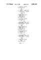
With reference now to FIG. 7, a flowchart is shown of a method for controlling receipt of voice messages according to the present invention. The method uses the line interface unit 200 as described above as well as the voice message facility 18, which normally includes access prevention circuitry 19 (as shown in FIG. 5) for preventing storage of voice messagesunless predetermined access codes are received and verified by the access prevention circuitry.
The method begins at step 250 when a call is initiated to the called station. At step 252, a test is made to determine, using the monitor and detector circuits of the line interface unit, whether a predetermined condition (e.g., busy/no answer or ring/no answer) exists at the called station. If the predetermined condition exists (i.e., if the call cannot be completed), the method continues at step 254 by connecting the speech circuit 210 to the calling station to thereby enable the speech circuit toissue the prompt. At step 256, the speech circuit is activated, under the control of the control circuit 218, to issue the prompt to the caller at the calling station. A test 258 is then made to determine, using the monitor and detector circuits, whether a predetermined code has been received from the calling station indicating that the caller desires to leave a voice message for the called station. If the predetermined code has been received from the calling station, the method continues at step 260 to connect the signaling circuit 212 to the central office to thereby enable the signaling circuit to signal the voice message facility. At step262, the signaling circuit is activated, under the control of the control circuit, to signal the voice message facility. Thereafter, at step 264, a test is made to determine, using the monitor and detector circuits, whether a predetermined code has been received from the voice message facility. If the predetermined code has been received from the voice message facility, the method continues at step 266 to transmit a predetermined data string from the line interface unit to the voice message facility. As noted above, preferably the predetermined data stringincluding information that, once recognized by the access prevention circuitry 19 means of the voice message facility, enables the voice message to be stored and forwarded from the voice message facility withoutentry of the predetermined access codes normally required by the access prevention circuitry.
Although the invention has been described and illustrated in detail, it should be appreciated that the same is by way of illustration and example only. The spirit and scope of the present invention are to be limited onlyby the terms of the appended claims.

Claims (5)

We claim:
1. A line interface unit for controlling receipt and delivery of voice messages over a telephone system having a voice message facility, the voice message facility connectible to at least one calling station and a called station and normally having access prevention means for preventing storage and forwarding of voice messages unless predetermined access codes are received and verified by the access prevention means, the calling station connected to a central office, comprising:
a switch connected to the central office and having first and second positions and wherein signals are connected directly between the calling station and the central office when the switch is in the first position;
means for signaling the voice message facility;
means for monitoring call progress upon call initiation to the called station;
means connected to the monitoring means for detecting a predetermined condition at the called station upon call initiation to the called station, for detecting receipt of a first predetermined code from the calling station indicating that the caller desires to leave a voice message for the called station at the caller's expense, and for detecting receipt of a second predetermined code from the voice message facility;
control means connected to the detecting means and the switch, the control means responsive to receipt of the first predetermined code from the calling station for switching the switch from its first position to its second position to enable the signaling means to signal the voice message facility;
wherein after signaling the voice message facility the control means is responsive to receipt of the second predetermined code from the voice message facility for switching the switch from its second position back to its first position to connect the calling station to the voice message facility; and
wherein after connection of the calling station to the voice message facility the control means transmits a predetermined data string to the voice message facility, the predetermined data string including information that, once recognized by the access prevention means of the voice message facility, enables the voice message to be stored and forwarded from the voice message facility without entry of the predetermined access codes normally required by the access prevention means.
2. The line interface unit as described in claim 1 wherein the predetermined data string comprises a number of the calling station, a predetermined number of digits representing a destination number of the called station, and billing information for use in billing the calling station.
3. A method, using a line interface unit, for controlling receipt and delivery of voice messages over a telephone system having a voice message facility connectible to at least one calling station and a called station via a central office, the voice message facility normally having access prevention means for preventing storage of voice messages unless predetermined access codes are received and verified by the access prevention means, wherein the line interface unit includes a monitor circuit for monitoring tip and ring lines of the calling station, a speech circuit for issuing a predetermined prompt to a caller at the calling station, a signaling circuit for signaling the voice message facility, a detector circuit connected to the monitor circuit for detecting signals on the tip and ring lines and a control circuit for controlling the operation of the line interface unit, comprising the steps of:
(a) determining, using the monitor circuit and the detector circuit, whether a predetermined condition exists at the called station upon call initiation to the called station;
(b) if the predetermined condition exists, connecting the speech circuit to the calling station to thereby enable the speech circuit to issue the prompt;
(c) activating, under the control of the control circuit, the speech circuit to issue the prompt to the caller at the calling station;
(d) determining, using the monitor circuit and the detector circuit, whether a predetermined code has been received from the calling station indicating that the caller desires to leave a voice message for the called station;
(e) if the predetermined code has been received from the calling station, connecting the signaling circuit to the central office to thereby enable the signaling circuit to signal the voice message facility;
(f) activating, under the control of the control circuit, the signaling circuit to signal the voice message facility;
(g) determining, using the monitor circuit and the detector circuit, whether a predetermined code has been received from the voice message facility; and
(h) if the predetermined code has been received from the voice message facility, transmitting a predetermined data string from the line interface unit to the voice message facility, the predetermined data string including information that, once recognized by the access prevention means of the voice message facility, enables the voice message to be stored and forwarded from the voice message facility without entry of the predetermined access codes normally required by the access prevention means.
4. The method as described in claim 3 wherein the predetermined data string comprises a number of the calling station, a predetermined number of digits representing a destination number of the called station, and billing information for use in billing the calling station.
5. A method, using a line interface unit, for controlling receipt and delivery of voice messages over a telephone system having a voice message facility connectible to at least one calling station and a called station via a central office, the line interface unit including a monitor circuit for monitoring tip and ring lines of the calling station, a speech circuit for issuing a predetermined prompt to a caller at the calling station, a signaling circuit for signaling the voice message facility, a detector circuit connected to the monitor circuit for detecting signals on the tip and ring lines and a control circuit for controlling the operation of the line interface unit, comprising the steps of:
(a) determining, using the monitor circuit and the detector circuit, whether a busy or ring/no answer condition exists at the called station upon call initiation to the called station;
(b) if a busy or ring/no answer condition exists, connecting the speech circuit to the calling station to thereby enable the speech circuit to issue the prompt;
(c) activating the speech circuit to issue the prompt to the caller at the calling station;
(d) determining, using the monitor circuit and the detector circuit, whether a predetermined code has been received from the calling station indicating that the caller desires to leave a voice message for the called station;
(e) if the predetermined code has been received from the calling station, connecting the signaling circuit to the central office to thereby enable the signaling circuit to signal the voice message facility;
(f) activating the signaling circuit to signal the voice message facility;
(g) determining, using the monitor circuit and the detector circuit, whether a predetermined code has been received from the voice message facility; and
(h) if the predetermined code has been received from the voice message facility, transmitting a predetermined data string from the line interface unit to the voice message facility, the predetermined data string including a telephone number of the calling station and a destination number of the called station.
US07/342,480 1988-06-22 1989-04-24 Method and apparatus for caller-controlled receipt and delivery of voice messages Expired - Lifetime US4901341A (en)

Priority Applications (10)

Application Number Priority Date Filing Date Title
US07/342,480 US4901341A (en) 1988-06-22 1989-04-24 Method and apparatus for caller-controlled receipt and delivery of voice messages
US07/478,674 US5036533A (en) 1989-04-24 1990-02-12 System for providing automatic voice messaging in a digital network environment
AU53845/90A AU5384590A (en) 1989-04-24 1990-04-24 Method and apparatus for caller-controlled receipt and delivery of voice messages
JP2106663A JPH0362764A (en) 1989-04-24 1990-04-24 Line interface unit and method of controlling transmission and reception of voice message using the same
CA002015243A CA2015243C (en) 1989-04-24 1990-04-24 Method and apparatus for caller-controlled receipt and delivery of voice messages
EP19900304400 EP0432866A3 (en) 1989-04-24 1990-04-24 Line interface unit
US08/054,853 US5381465A (en) 1988-06-22 1993-04-28 System for providing automatic voice messaging in a digital network environment
US08/370,055 US5646980A (en) 1988-06-22 1995-01-09 System for providing automatic voice messaging in a digital network environment
US08/718,144 US5694456A (en) 1988-06-22 1996-09-18 System for providing automatic voice messaging in a digital network environment
US08/925,968 US5982858A (en) 1988-06-22 1997-09-09 System for providing automatic voice messaging in a digital network environment

Applications Claiming Priority (2)

Application Number Priority Date Filing Date Title
US07/209,891 US4825460A (en) 1988-06-22 1988-06-22 Line interface unit for caller-controlled receipt and delivery of voice messages
US07/342,480 US4901341A (en) 1988-06-22 1989-04-24 Method and apparatus for caller-controlled receipt and delivery of voice messages

Related Parent Applications (1)

Application Number Title Priority Date Filing Date
US07/209,891 Continuation-In-Part US4825460A (en) 1988-06-21 1988-06-22 Line interface unit for caller-controlled receipt and delivery of voice messages

Related Child Applications (1)

Application Number Title Priority Date Filing Date
US07/478,674 Continuation-In-Part US5036533A (en) 1988-06-22 1990-02-12 System for providing automatic voice messaging in a digital network environment

Publications (1)

Publication Number Publication Date
US4901341A true US4901341A (en) 1990-02-13

Family

ID=23342005

Family Applications (1)

Application Number Title Priority Date Filing Date
US07/342,480 Expired - Lifetime US4901341A (en) 1988-06-22 1989-04-24 Method and apparatus for caller-controlled receipt and delivery of voice messages

Country Status (5)

Country Link
US (1) US4901341A (en)
EP (1) EP0432866A3 (en)
JP (1) JPH0362764A (en)
AU (1) AU5384590A (en)
CA (1) CA2015243C (en)

Cited By (44)

* Cited by examiner, † Cited by third party
Publication number Priority date Publication date Assignee Title
US4985913A (en) * 1989-08-29 1991-01-15 Stephen R. Shalom Multiple message answering machine keyed to the incoming phone number
US5007077A (en) * 1990-03-23 1991-04-09 Conway Engineering, Inc. Coin telephone message and management system
US5131024A (en) * 1990-05-16 1992-07-14 Messager Partners Method and apparatus for providing proactive call services following call completion
US5134646A (en) * 1989-05-11 1992-07-28 Unisys Corporation Voice messaging method and apparatus for pay phone telephone systems
EP0535784A2 (en) * 1991-09-30 1993-04-07 Gpt Limited Message transmission system
US5278664A (en) * 1990-05-23 1994-01-11 Jang Gi Su Method for increasing communication efficiency in a multiport facsimile
US5317627A (en) * 1990-10-01 1994-05-31 United States Advanced Network, Inc. Enhanced wide area audio response network
US5333266A (en) * 1992-03-27 1994-07-26 International Business Machines Corporation Method and apparatus for message handling in computer systems
US5335266A (en) * 1990-10-01 1994-08-02 United States Advance Network, Inc. Automated telecommunication peripheral system
GB2287609A (en) * 1994-03-15 1995-09-20 Mitel Corp Handling follow-up telephone call messages
US5461665A (en) * 1993-03-01 1995-10-24 Executone Information Systems, Inc. Voice processing system
US5471519A (en) * 1993-02-26 1995-11-28 Bellsouth Corporation Communications monitoring and control system
US5535264A (en) * 1993-02-10 1996-07-09 Unisys Corporation Prompt issuing protocol for an intercept voice messaging system
GB2297011A (en) * 1995-01-13 1996-07-17 Telsis Holdings Ltd Secure access telephony server systems
US5590171A (en) * 1994-07-07 1996-12-31 Bellsouth Corporation Method and apparatus for communications monitoring
US5646980A (en) * 1988-06-22 1997-07-08 Messagerpartners System for providing automatic voice messaging in a digital network environment
US5712907A (en) * 1995-09-18 1998-01-27 Open Port Technology, Inc. Pro-active message delivery system and method
US5940740A (en) * 1996-10-25 1999-08-17 At&T Wireless Services, Inc. Method and apparatus for message transmission verification
EP0782314A3 (en) * 1995-12-29 2000-05-24 AT&T Corp. Called party mailbox service
US6272215B1 (en) 1996-12-06 2001-08-07 At&T Corp. Intelligent call redirection
US6424702B1 (en) 1999-01-28 2002-07-23 Ameritech Corporation Method and system for termination blocking of message delivery service
US6442244B1 (en) 1998-10-13 2002-08-27 At&T Corp. Method and apparatus for selective audio logo and/or announcements in a telecommunications network
US6560323B2 (en) 1994-04-19 2003-05-06 T-Netix, Inc. Computer-based method and apparatus for controlling, monitoring, recording and reporting telephone access
US6611583B1 (en) 1994-04-19 2003-08-26 T-Netix, Inc. Computer-based method and apparatus for controlling, monitoring, recording and reporting telephone access
US6665380B1 (en) 1999-01-11 2003-12-16 T-Netix, Inc. Inmate messaging system and method
US6665376B1 (en) 1998-10-23 2003-12-16 T-Netix, Inc. Selectively activated integrated real-time recording of telephone conversations with automated documentation of consent to call recording
US6668045B1 (en) 2000-10-30 2003-12-23 T-Netix, Inc. Message screening, delivery and billing system
US6754830B1 (en) * 1999-02-26 2004-06-22 Nokia Multimedia Terminals Oy Method and coupling arrangement for preventing unauthorized access to a microprocessor
US6763099B1 (en) 1999-11-05 2004-07-13 T-Netix, Inc. Advanced three way call detection system and method using spread spectrum techniques
US6920209B1 (en) 1994-04-19 2005-07-19 T-Netix, Inc. Computer-based method and apparatus for controlling, monitoring, recording and reporting telephone access
US20060129644A1 (en) * 2004-12-14 2006-06-15 Brad Owen Email filtering system and method
US20060149823A1 (en) * 2005-01-06 2006-07-06 The Go Daddy Group, Inc Electronic mail system and method
US20060184634A1 (en) * 2006-05-18 2006-08-17 The Go Daddy Group, Inc. Electronic mail system using email tickler
US7248680B1 (en) 1994-04-19 2007-07-24 T-Netix, Inc. Computer-based method and apparatus for controlling, monitoring, recording and reporting telephone access
US20070242658A1 (en) * 2006-04-13 2007-10-18 Evercom Systems, Inc. Unauthorized call activity detection and prevention systems and methods for a voice over internet protocol environment
US20080019487A1 (en) * 2003-04-24 2008-01-24 At&T Knowledge Ventures, L.P. Method and system for termination blocking of message delivery service in a swtich-based telecommunication system
US7505406B1 (en) 2001-07-13 2009-03-17 Evercom Systems, Inc. Public telephone control with voice over internet protocol transmission
US7529357B1 (en) 2003-08-15 2009-05-05 Evercom Systems, Inc. Inmate management and call processing systems and methods
US7899167B1 (en) 2003-08-15 2011-03-01 Securus Technologies, Inc. Centralized call processing
US8000269B1 (en) 2001-07-13 2011-08-16 Securus Technologies, Inc. Call processing with voice over internet protocol transmission
US9560193B1 (en) 2002-04-29 2017-01-31 Securus Technologies, Inc. Systems and methods for detecting a call anomaly using biometric identification
US9990683B2 (en) 2002-04-29 2018-06-05 Securus Technologies, Inc. Systems and methods for acquiring, accessing, and analyzing investigative information
US10115080B2 (en) 2002-04-29 2018-10-30 Securus Technologies, Inc. System and method for proactively establishing a third-party payment account for services rendered to a resident of a controlled-environment facility
US10796392B1 (en) 2007-05-22 2020-10-06 Securus Technologies, Llc Systems and methods for facilitating booking, bonding and release

Families Citing this family (2)

* Cited by examiner, † Cited by third party
Publication number Priority date Publication date Assignee Title
US5099509A (en) * 1987-04-17 1992-03-24 Dytel Corporation Integration of voice store and forward facility
US8072109B2 (en) 2006-03-16 2011-12-06 Panasonic Corporation Radial anisotropic magnet manufacturing method, permanent magnet motor using radial anisotropic magnet, and iron core-equipped permanent magnet motor

Citations (14)

* Cited by examiner, † Cited by third party
Publication number Priority date Publication date Assignee Title
US3728486A (en) * 1971-08-26 1973-04-17 C Kraus Voicegram service
US3899645A (en) * 1971-12-16 1975-08-12 Yeda Res & Dev Processor for controlling the operation of a telephone
US4371752A (en) * 1979-11-26 1983-02-01 Ecs Telecommunications, Inc. Electronic audio communication system
GB2130848A (en) * 1982-10-26 1984-06-06 Nihon Resuko Kk Telephone call transfer apparatus with receiving announcing means
EP0112967A1 (en) * 1982-12-30 1984-07-11 Wang Laboratories Inc. Call interceptor
EP0166393A2 (en) * 1984-06-25 1986-01-02 Honeywell Inc. Telephone interface system
US4600809A (en) * 1983-11-30 1986-07-15 Kabushiki Kaisha Toshiba Telephone systems
US4602129A (en) * 1979-11-26 1986-07-22 Vmx, Inc. Electronic audio communications system with versatile message delivery
US4674116A (en) * 1985-07-03 1987-06-16 Amtelco Telephone line concentrator without switching matrix
US4696028A (en) * 1984-03-26 1987-09-22 Dytel Corporation PBX Intercept and caller interactive attendant bypass system
US4766604A (en) * 1986-11-07 1988-08-23 Messagephone, Inc. Method for receiving and delivering voice messages
US4777647A (en) * 1986-09-29 1988-10-11 Digital Telecommunications Systems, Inc. Pay station telephone interface
US4792967A (en) * 1986-02-20 1988-12-20 Opcom PBX DID and E and M tie trunk integration adapter and method
US4809321A (en) * 1986-09-22 1989-02-28 Dytel Corporation Busy/no-answer call completion equipment

Family Cites Families (2)

* Cited by examiner, † Cited by third party
Publication number Priority date Publication date Assignee Title
JPS5990451A (en) * 1982-11-15 1984-05-24 Fujitsu Ltd Information transfer system
US4825460A (en) * 1988-06-22 1989-04-25 Messagephone, Inc. Line interface unit for caller-controlled receipt and delivery of voice messages

Patent Citations (14)

* Cited by examiner, † Cited by third party
Publication number Priority date Publication date Assignee Title
US3728486A (en) * 1971-08-26 1973-04-17 C Kraus Voicegram service
US3899645A (en) * 1971-12-16 1975-08-12 Yeda Res & Dev Processor for controlling the operation of a telephone
US4371752A (en) * 1979-11-26 1983-02-01 Ecs Telecommunications, Inc. Electronic audio communication system
US4602129A (en) * 1979-11-26 1986-07-22 Vmx, Inc. Electronic audio communications system with versatile message delivery
GB2130848A (en) * 1982-10-26 1984-06-06 Nihon Resuko Kk Telephone call transfer apparatus with receiving announcing means
EP0112967A1 (en) * 1982-12-30 1984-07-11 Wang Laboratories Inc. Call interceptor
US4600809A (en) * 1983-11-30 1986-07-15 Kabushiki Kaisha Toshiba Telephone systems
US4696028A (en) * 1984-03-26 1987-09-22 Dytel Corporation PBX Intercept and caller interactive attendant bypass system
EP0166393A2 (en) * 1984-06-25 1986-01-02 Honeywell Inc. Telephone interface system
US4674116A (en) * 1985-07-03 1987-06-16 Amtelco Telephone line concentrator without switching matrix
US4792967A (en) * 1986-02-20 1988-12-20 Opcom PBX DID and E and M tie trunk integration adapter and method
US4809321A (en) * 1986-09-22 1989-02-28 Dytel Corporation Busy/no-answer call completion equipment
US4777647A (en) * 1986-09-29 1988-10-11 Digital Telecommunications Systems, Inc. Pay station telephone interface
US4766604A (en) * 1986-11-07 1988-08-23 Messagephone, Inc. Method for receiving and delivering voice messages

Non-Patent Citations (6)

* Cited by examiner, † Cited by third party
Title
"Busy Call Diverter", R. L. Brady et al, IBM Technical Disclosure Bulletin, vol. 25, No. 4, Sep. 1982, pp. 2231-2232.
"Calling or Called Number Feature for Telephone System", R. L. Brady et al, IBM Technical Disclosure Bulletin, vol. 25, No. 7B, Dec. 1982, pp. 3961-3962.
"Unanswered Call Diverter", R. L. Brady et al., IBM Technical Disclosure Bulletin, vol. 25, No. 7A, Dec. 1982, pp. 3480-3481.
Busy Call Diverter , R. L. Brady et al, IBM Technical Disclosure Bulletin , vol. 25, No. 4, Sep. 1982, pp. 2231 2232. *
Calling or Called Number Feature for Telephone System , R. L. Brady et al, IBM Technical Disclosure Bulletin , vol. 25, No. 7B, Dec. 1982, pp. 3961 3962. *
Unanswered Call Diverter , R. L. Brady et al., IBM Technical Disclosure Bulletin , vol. 25, No. 7A, Dec. 1982, pp. 3480 3481. *

Cited By (77)

* Cited by examiner, † Cited by third party
Publication number Priority date Publication date Assignee Title
US5694456A (en) * 1988-06-22 1997-12-02 Messagerpartners System for providing automatic voice messaging in a digital network environment
US5646980A (en) * 1988-06-22 1997-07-08 Messagerpartners System for providing automatic voice messaging in a digital network environment
US5982858A (en) * 1988-06-22 1999-11-09 Messagephone, Inc. System for providing automatic voice messaging in a digital network environment
US5134646A (en) * 1989-05-11 1992-07-28 Unisys Corporation Voice messaging method and apparatus for pay phone telephone systems
US5278895A (en) * 1989-05-11 1994-01-11 Unisys Corporation Voice messaging method and apparatus for pay phone telephone systems
US4985913A (en) * 1989-08-29 1991-01-15 Stephen R. Shalom Multiple message answering machine keyed to the incoming phone number
US5007077A (en) * 1990-03-23 1991-04-09 Conway Engineering, Inc. Coin telephone message and management system
US5131024A (en) * 1990-05-16 1992-07-14 Messager Partners Method and apparatus for providing proactive call services following call completion
US5278664A (en) * 1990-05-23 1994-01-11 Jang Gi Su Method for increasing communication efficiency in a multiport facsimile
US5487103A (en) * 1990-10-01 1996-01-23 United States Advanced Network, Inc. Enhanced wide area audio response network
US5692034A (en) * 1990-10-01 1997-11-25 United States Advanced Network, Inc. Customized, billing-controlled call bridging system
US5355403A (en) * 1990-10-01 1994-10-11 United States Advance Network, Inc. Customized, billing-controlled call bridging system
US5943403A (en) * 1990-10-01 1999-08-24 United States Advance Network, Inc. Customized, billing-controlled call bridging system
US5335266A (en) * 1990-10-01 1994-08-02 United States Advance Network, Inc. Automated telecommunication peripheral system
US5835572A (en) * 1990-10-01 1998-11-10 United States Advanced Network, Inc. Customized, billing controlled call bridging system
US5652785A (en) * 1990-10-01 1997-07-29 United Stated Advanced Network, Inc. Enhanced wide area audio response network
US5317627A (en) * 1990-10-01 1994-05-31 United States Advanced Network, Inc. Enhanced wide area audio response network
US5581607A (en) * 1990-10-01 1996-12-03 United States Advanced Network, Inc. Customized, billing-controlled call bridging system
US5619556A (en) * 1990-10-01 1997-04-08 United States Advanced Network, Inc. Automated telecommunication peripheral system
EP0535784A2 (en) * 1991-09-30 1993-04-07 Gpt Limited Message transmission system
EP0535784A3 (en) * 1991-09-30 1993-06-09 Gpt Limited Message transmission system
US5333266A (en) * 1992-03-27 1994-07-26 International Business Machines Corporation Method and apparatus for message handling in computer systems
US5535264A (en) * 1993-02-10 1996-07-09 Unisys Corporation Prompt issuing protocol for an intercept voice messaging system
US5471519A (en) * 1993-02-26 1995-11-28 Bellsouth Corporation Communications monitoring and control system
US5461665A (en) * 1993-03-01 1995-10-24 Executone Information Systems, Inc. Voice processing system
US5625682A (en) * 1994-03-15 1997-04-29 Mitel Corporation Help desk improvement
GB2287609A (en) * 1994-03-15 1995-09-20 Mitel Corp Handling follow-up telephone call messages
GB2287609B (en) * 1994-03-15 1998-10-21 Mitel Corp A method of handling a telephone message
US20070041545A1 (en) * 1994-04-19 2007-02-22 Gainsboro Jay L Computer-based method and apparatus for controlling, monitoring, recording and reporting telephone access
US6920209B1 (en) 1994-04-19 2005-07-19 T-Netix, Inc. Computer-based method and apparatus for controlling, monitoring, recording and reporting telephone access
US7889847B2 (en) 1994-04-19 2011-02-15 Securus Technologies Holdings, Inc. Computer-based method and apparatus for controlling, monitoring, recording and reporting telephone access
US7248680B1 (en) 1994-04-19 2007-07-24 T-Netix, Inc. Computer-based method and apparatus for controlling, monitoring, recording and reporting telephone access
US7106843B1 (en) 1994-04-19 2006-09-12 T-Netix, Inc. Computer-based method and apparatus for controlling, monitoring, recording and reporting telephone access
US6611583B1 (en) 1994-04-19 2003-08-26 T-Netix, Inc. Computer-based method and apparatus for controlling, monitoring, recording and reporting telephone access
US6560323B2 (en) 1994-04-19 2003-05-06 T-Netix, Inc. Computer-based method and apparatus for controlling, monitoring, recording and reporting telephone access
US5590171A (en) * 1994-07-07 1996-12-31 Bellsouth Corporation Method and apparatus for communications monitoring
GB2297011B (en) * 1995-01-13 1999-03-10 Telsis Holdings Ltd Secure access telephony server systems
GB2297011A (en) * 1995-01-13 1996-07-17 Telsis Holdings Ltd Secure access telephony server systems
US6393016B2 (en) 1995-09-18 2002-05-21 Net2Phone, Inc. Telephony signal transmission over a data communications network
US6032192A (en) * 1995-09-18 2000-02-29 Open Port Technology, Inc. Pro-active message delivery system and method
US5712907A (en) * 1995-09-18 1998-01-27 Open Port Technology, Inc. Pro-active message delivery system and method
EP0782314A3 (en) * 1995-12-29 2000-05-24 AT&T Corp. Called party mailbox service
US5940740A (en) * 1996-10-25 1999-08-17 At&T Wireless Services, Inc. Method and apparatus for message transmission verification
US20050188033A1 (en) * 1996-10-25 2005-08-25 David Aas Method and apparatus for message transmission verification
US6845391B1 (en) * 1996-10-25 2005-01-18 At&T Wireless Services, Inc. Method and apparatus for message transmission verification
US7328248B2 (en) 1996-10-25 2008-02-05 Cingular Wireless Ii, Llc Method and apparatus for message transmission verification
US6272215B1 (en) 1996-12-06 2001-08-07 At&T Corp. Intelligent call redirection
US6442244B1 (en) 1998-10-13 2002-08-27 At&T Corp. Method and apparatus for selective audio logo and/or announcements in a telecommunications network
US6665376B1 (en) 1998-10-23 2003-12-16 T-Netix, Inc. Selectively activated integrated real-time recording of telephone conversations with automated documentation of consent to call recording
US6665380B1 (en) 1999-01-11 2003-12-16 T-Netix, Inc. Inmate messaging system and method
US7010101B2 (en) 1999-01-28 2006-03-07 Sbc Properties, L.P. Method and system for termination blocking of message delivery service
US6424702B1 (en) 1999-01-28 2002-07-23 Ameritech Corporation Method and system for termination blocking of message delivery service
US20060171518A1 (en) * 1999-01-28 2006-08-03 Blumenschein Gordon L Method and system for termination blocking of message delivery service
US6687337B2 (en) 1999-01-28 2004-02-03 Sbc Properties, L.P. Method and system for termination blocking of message delivery service
US20040141592A1 (en) * 1999-01-28 2004-07-22 Blumenschein Gordon Lynn Method and system for termination blocking of message delivery service
US6754830B1 (en) * 1999-02-26 2004-06-22 Nokia Multimedia Terminals Oy Method and coupling arrangement for preventing unauthorized access to a microprocessor
US6763099B1 (en) 1999-11-05 2004-07-13 T-Netix, Inc. Advanced three way call detection system and method using spread spectrum techniques
US6668045B1 (en) 2000-10-30 2003-12-23 T-Netix, Inc. Message screening, delivery and billing system
US7505406B1 (en) 2001-07-13 2009-03-17 Evercom Systems, Inc. Public telephone control with voice over internet protocol transmission
US8000269B1 (en) 2001-07-13 2011-08-16 Securus Technologies, Inc. Call processing with voice over internet protocol transmission
US9990683B2 (en) 2002-04-29 2018-06-05 Securus Technologies, Inc. Systems and methods for acquiring, accessing, and analyzing investigative information
US9560193B1 (en) 2002-04-29 2017-01-31 Securus Technologies, Inc. Systems and methods for detecting a call anomaly using biometric identification
US10115080B2 (en) 2002-04-29 2018-10-30 Securus Technologies, Inc. System and method for proactively establishing a third-party payment account for services rendered to a resident of a controlled-environment facility
US10178224B2 (en) 2002-04-29 2019-01-08 Securus Technologies, Inc. Systems and methods for detecting a call anomaly using biometric identification
US20080019487A1 (en) * 2003-04-24 2008-01-24 At&T Knowledge Ventures, L.P. Method and system for termination blocking of message delivery service in a swtich-based telecommunication system
US7529357B1 (en) 2003-08-15 2009-05-05 Evercom Systems, Inc. Inmate management and call processing systems and methods
US7899167B1 (en) 2003-08-15 2011-03-01 Securus Technologies, Inc. Centralized call processing
US8340260B1 (en) 2003-08-15 2012-12-25 Securus Technologies, Inc. Inmate management and call processing systems and methods
US10740861B1 (en) 2003-11-24 2020-08-11 Securus Technologies, Inc. Systems and methods for acquiring, accessing, and analyzing investigative information
US7580982B2 (en) 2004-12-14 2009-08-25 The Go Daddy Group, Inc. Email filtering system and method
US20060129644A1 (en) * 2004-12-14 2006-06-15 Brad Owen Email filtering system and method
US20060149823A1 (en) * 2005-01-06 2006-07-06 The Go Daddy Group, Inc Electronic mail system and method
US7916845B2 (en) 2006-04-13 2011-03-29 Securus Technologies, Inc. Unauthorized call activity detection and prevention systems and methods for a Voice over Internet Protocol environment
US20070242658A1 (en) * 2006-04-13 2007-10-18 Evercom Systems, Inc. Unauthorized call activity detection and prevention systems and methods for a voice over internet protocol environment
US20060184635A1 (en) * 2006-05-18 2006-08-17 The Go Daddy Group, Inc. Electronic mail method using email tickler
US20060184634A1 (en) * 2006-05-18 2006-08-17 The Go Daddy Group, Inc. Electronic mail system using email tickler
US10796392B1 (en) 2007-05-22 2020-10-06 Securus Technologies, Llc Systems and methods for facilitating booking, bonding and release

Also Published As

Publication number Publication date
CA2015243C (en) 2000-07-11
CA2015243A1 (en) 1990-10-24
AU5384590A (en) 1990-10-25
EP0432866A3 (en) 1993-03-17
JPH0362764A (en) 1991-03-18
EP0432866A2 (en) 1991-06-19

Similar Documents

Publication Publication Date Title
US4901341A (en) Method and apparatus for caller-controlled receipt and delivery of voice messages
US4825460A (en) Line interface unit for caller-controlled receipt and delivery of voice messages
US4766604A (en) Method for receiving and delivering voice messages
US5381465A (en) System for providing automatic voice messaging in a digital network environment
US5036533A (en) System for providing automatic voice messaging in a digital network environment
US4930152A (en) Call return telephone service
US5502761A (en) Apparatus and method for relaying calling information to a pager or alternate telephone
AU654280B2 (en) Long distance telephone switching system with enhanced subscriber services
EP0360493B1 (en) More efficient call handling for operator assistance calls
US5825867A (en) Enhanced call waiting
US5278895A (en) Voice messaging method and apparatus for pay phone telephone systems
US6026156A (en) Enhanced call waiting
US4086438A (en) Automatic interconnection system
US4731818A (en) Self-computing credit card telephone paystation method and system
US6430270B1 (en) Automatic conversational record
US5535264A (en) Prompt issuing protocol for an intercept voice messaging system
JPH02299354A (en) Automatic speech and data message processing
US6393106B1 (en) Telephone answering device which records voice message of third party caller
CA2272236C (en) Voice messaging system which allows a remote user to return a call without disconnecting from a telephone line
JPH07162522A (en) Voice storage device
CA2347034A1 (en) Enhanced call waiting
WO2000011852A1 (en) Automated call user interface

Legal Events

Date Code Title Description
STCF Information on status: patent grant

Free format text: PATENTED CASE

REMI Maintenance fee reminder mailed
REFU Refund

Free format text: REFUND - 3.5 YR SURCHARGE - LATE PMT W/IN 6 MO, SMALL ENTITY (ORIGINAL EVENT CODE: R286); ENTITY STATUS OF PATENT OWNER: LARGE ENTITY

Free format text: REFUND - PAYMENT OF MAINTENANCE FEE, 4TH YR, SMALL ENTITY (ORIGINAL EVENT CODE: R283); ENTITY STATUS OF PATENT OWNER: LARGE ENTITY

FPAY Fee payment

Year of fee payment: 4

SULP Surcharge for late payment
REFU Refund

Free format text: REFUND OF EXCESS PAYMENTS PROCESSED (ORIGINAL EVENT CODE: R169); ENTITY STATUS OF PATENT OWNER: LARGE ENTITY

FEPP Fee payment procedure

Free format text: PAT HLDR NO LONGER CLAIMS SMALL ENT STAT AS SMALL BUSINESS (ORIGINAL EVENT CODE: LSM2); ENTITY STATUS OF PATENT OWNER: LARGE ENTITY

REFU Refund

Free format text: REFUND - PAYMENT OF MAINTENANCE FEE, 8TH YEAR, LARGE ENTITY (ORIGINAL EVENT CODE: R184); ENTITY STATUS OF PATENT OWNER: LARGE ENTITY

FPAY Fee payment

Year of fee payment: 8

FEPP Fee payment procedure

Free format text: PAYOR NUMBER ASSIGNED (ORIGINAL EVENT CODE: ASPN); ENTITY STATUS OF PATENT OWNER: LARGE ENTITY

FPAY Fee payment

Year of fee payment: 12