US4901261A - Retractable handle and latch for portable computers - Google Patents
Retractable handle and latch for portable computers Download PDFInfo
- Publication number
- US4901261A US4901261A US07/265,110 US26511088A US4901261A US 4901261 A US4901261 A US 4901261A US 26511088 A US26511088 A US 26511088A US 4901261 A US4901261 A US 4901261A
- Authority
- US
- United States
- Prior art keywords
- assembly
- handle
- lid
- latch
- computer
- Prior art date
- Legal status (The legal status is an assumption and is not a legal conclusion. Google has not performed a legal analysis and makes no representation as to the accuracy of the status listed.)
- Expired - Lifetime
Links
Images


Classifications
-
- G—PHYSICS
- G06—COMPUTING; CALCULATING OR COUNTING
- G06F—ELECTRIC DIGITAL DATA PROCESSING
- G06F1/00—Details not covered by groups G06F3/00 - G06F13/00 and G06F21/00
- G06F1/16—Constructional details or arrangements
- G06F1/1613—Constructional details or arrangements for portable computers
- G06F1/1615—Constructional details or arrangements for portable computers with several enclosures having relative motions, each enclosure supporting at least one I/O or computing function
- G06F1/1616—Constructional details or arrangements for portable computers with several enclosures having relative motions, each enclosure supporting at least one I/O or computing function with folding flat displays, e.g. laptop computers or notebooks having a clamshell configuration, with body parts pivoting to an open position around an axis parallel to the plane they define in closed position
-
- G—PHYSICS
- G06—COMPUTING; CALCULATING OR COUNTING
- G06F—ELECTRIC DIGITAL DATA PROCESSING
- G06F1/00—Details not covered by groups G06F3/00 - G06F13/00 and G06F21/00
- G06F1/16—Constructional details or arrangements
- G06F1/1613—Constructional details or arrangements for portable computers
- G06F1/1633—Constructional details or arrangements of portable computers not specific to the type of enclosures covered by groups G06F1/1615 - G06F1/1626
- G06F1/1656—Details related to functional adaptations of the enclosure, e.g. to provide protection against EMI, shock, water, or to host detachable peripherals like a mouse or removable expansions units like PCMCIA cards, or to provide access to internal components for maintenance or to removable storage supports like CDs or DVDs, or to mechanically mount accessories
-
- G—PHYSICS
- G06—COMPUTING; CALCULATING OR COUNTING
- G06F—ELECTRIC DIGITAL DATA PROCESSING
- G06F1/00—Details not covered by groups G06F3/00 - G06F13/00 and G06F21/00
- G06F1/16—Constructional details or arrangements
- G06F1/1613—Constructional details or arrangements for portable computers
- G06F1/1633—Constructional details or arrangements of portable computers not specific to the type of enclosures covered by groups G06F1/1615 - G06F1/1626
- G06F1/1675—Miscellaneous details related to the relative movement between the different enclosures or enclosure parts
- G06F1/1679—Miscellaneous details related to the relative movement between the different enclosures or enclosure parts for locking or maintaining the movable parts of the enclosure in a fixed position, e.g. latching mechanism at the edge of the display in a laptop or for the screen protective cover of a PDA
Definitions
- the display panel including the hinging hardware, fold flush with the upper surface of the keyboard and this is usually accomplished by accommodating the display panel with a recess into which the upper surface of the keyboard fits.
- the display panel be securely locked to the keyboard for transportation. It is also desirable that the locking or latching device be substantially flush with the sides of the computer to eliminate any unwanted protrusions that not only interfere with ease of portability but also detract from the aesthetics of the computer. Prior attempts to reach these objectives have produced partly satisfactory latches but they are somewhat prone to inadvertent release because the locking action is not completely positive.
- a locking mechanism is illustrated between the lid assembly and the keyboard that includes a linearly reciprocal hook-like lug in the lid and a cooperating undercut recess on the keyboard. The engaging faces on the hook lug and undercut recess are complementary but angled and thus tend to cam the lug out of the recess.
- a portable computer is provided with a base, a keyboard and lid pivotally mounted to the base with a retractable handle and side-mounted positive lid latches that are functionally interrelated so that extension of the handle actuates the latches, and the handle is retracted automatically as the lid is unlocked and opened.
- the positively retracted handle prevents the user from picking the computer up by the handle with the lid open and imposing loads on the lid pivot mounting.
- loads are transferred through the handle directly to the base and not through the lid. In this way the lid pivotal mounting does not have to be designed to carry the total computer weight.
- Eliminating the need for the operator to retract the handle is also important, not so much because manual handle retraction is difficult, but because the user will frequently simply neglect to retract the handle and the resulting protruding handle is prone to bumping adjacent obstacles and is aesthetically unpleasant in the work area.
- the present portable computer is provided with a pivotal lid assembly, housing an LCD display, that has linearly reciprocable latch operators on its sides and a channel-shaped peripheral recess that slidably receives a generally U-shaped retractable handle.
- the handle has spaced elongated arms with laterally projecting distal lugs that engage bars on the latch operators after the handle is partly extended to shift the latch operators to their engaged positions as the handle is fully extended. This permits the user to partly extend the handle assembly without resistance by light engagement of the hands on the sides of the handle, and then gain leverage by grasping the handle crossbar for complete extension and latch operation.
- These handle arms are also provided with elongated slots that slidably receive a follower connected to one end of a pair of retraction links that are pivotally mounted at their opposite ends adjacent and below the pivotal axis of the lid assembly on the computer base.
- This geometry causes the retraction link followers to engage the ends of the handle arm slots as the lid is opened, withdrawing the handle smoothly to its fully retracted position as the retraction links pivot up to a position near the axis of the pivotal mounting of the lid assembly.
- these retraction links also transfer all the handle load directly to the base without loading the lid pivotal mounting.
- the positive locking action of the latch mechanisms is achieved with a pivotally mounted locking pawl that has an elongated slot slidably receiving an actuating pin carried by one end of the linearly reciprocal latch operators.
- This locking pawl has a generally rectangular recess therein that forms a flat, parallel sided hook.
- the inner surface of a lid panel is flat and parallel to an inner surface of a keyboard panel, and both are fully engaged and clamped by the pawl hook sides in the engaged position, thereby providing a strictly positive locking action not provided in protable computer lid assembly latching mechanisms heretofore provided.
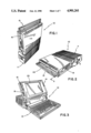
- FIG. 1 is a perspective view of the present portable computer resting in a vertical closed position with its handle extended;
- FIG. 2 is a perspective view of the portable computer illustrated in FIG. 1 in a horizontal closed position
- FIG. 3 is a perspective view of the portable computer illustrated in FIGS. 1 and 2 with its lid assembly open;
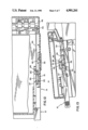
- FIG. 4 is a right side view of the portable computer illustrated in FIGS. 1 to 3 with its handle extended and latches actuated;
- FIG. 5 is an enlarged partly fragmentary right side view of the present portable computer with its handle extended and latches locked;
- FIG. 6 is a fragmentary exploded perspective view of the right handle arm and latch mechanism
- FIG. 7 is a fragmentary cross-section taken generally along line 7--7 of FIG. 5 illustrating the latch and handle retract mechanism
- FIG. 8 is a fragmentary cross-section taken generally along line 8--8 of FIG. 5 illustrating the right latch and handle retract mechanism
- FIG. 9 is a fragmentary cross-section taken generally along line 9--9 of FIG. 5 illustrating the right latch and handle retract mechanism
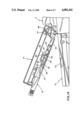
- FIG. 10 is a partly fragmented right side view of the present portable computer prior to handle extension
- FIG. 11 is a partly fragmented right side view of the present portable computer after complete handle extension
- FIG. 12 is a fragmentary longitudinal section of the right side handle retract and latch mechanism with the handle extended taken generally along line 12--12 of FIG. 5;
- FIG. 13 is a partly fragmented right side view of the present portable computer with its handle partly extended;
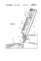
- FIG. 14 is a partly fragmented right side view of the present portable computer with the lid assembly partly open, and;
- FIG. 15 is a partly fragmented right side view of the present portable computer with the lid assembly fully open.
- a portable computer 10 is illustrated according to the present invention and is seen to generally include a transversely elongated base 11, a keyboard assembly13 and a lid assembly 14 pivotally mounted on base 11.
- a retractable handleassembly 15 is slidably mounted in a channel-shaped peripheral recess 16 inthe lid assembly 14, and the lid assembly 14 is selectively locked over thekeyboard assembly 13 by opposite latch assemblies 18 and 19 also mounted inthe sides of the lid assembly 14.
- the base 11 typically carries a central processing unit, memory circuitry, a hard drive, disk drives and a plurality of slots for additional optionalcomponents.
- the keyboard assembly 13 includes a plurality of keys of manually accessingthe central processing unit in the base 11.
- the pivotally mounted lid assembly 14 has a flat LCD screen assembly 23 mounted therein visible as seen in FIG. 3 when the lid is in its open position.
- the handle assembly 15 includes a straight rectangular cross member 22 connected to a pair of mirror image arms 24 spaced to slidably fit in siderecesses 25 that form a part of the channel-shaped recess 16 that slidably receives the handle assembly 15 and conceals it except for its outer surface which is flush in the retracted position shown in FIG. 3, for example.
- the portions of the handle assembly 15 on the opposite sides of the lid assembly 14 and the latch assemblies 18 and 19 are mirror images of one another so the following description of the right side portions thereof should be understood to apply to both sides equally.
- handle arm 24 has an integral elongated slide 27 extending outwardly therefrom that extends through an aperture 28 in the end of lid recess portion 25 and is slidable on inner lid panel surface 30as seen in FIGS. 7, 8 and 9. Lateral movement of the slide 27 is minimized by an elongated integral rib 32 projecting upwardly from lid surface 30.
- An elongated, substantially straight retraction link 34 is mounted on the same lid panel surface 30 with its side slidably engaging the outboard side of slide 27, and it has a cylindrical follower 36 threadedly carried at its distal end slidable in an elongated slot 38 in slide 27.
- the proximal end of retraction link 34 is pivoted to base 11 by a fixed pin 40carried in base slot 41, as seen in FIG. 6, which extends through a transversely slightly elongated aperture 43 in the proximal end of link 34.
- the location of slot 38 and the length of link 34 are selected so thatfollower 36 initially engages distal end 45 (FIG. 6) of slot 38 when the handle 15 is in a partly extended position with the lid partly open as illustrated in FIGS. 14.
- the lid assembly 14 is pivotally mounted to the base 11 by a pair of pivot boss assemblies 46 having an axis 47.
- the retraction link pivot pin 40 hasan axis offset forwardly from axis 47 approximately 0.25 inches and is below axis 47 approximately 1 5/16ths inches (in the horizontal position of the computer 10).
- lid pivot axis 47 and pivot pin 40 for the retracting links 34 is selected so that when the lid assembly 14 is pivoted to its fully open position illustrated in FIG. 15, links 34 will have dragged handle slides 27 sufficiently so that the handle cross member 22 is fully retracted into recess 16 and the handle 15 is flush with the ends and sides of the lid assembly 14.
- the elongated slide slots 38 permits the handle assembly 15 to be retractedmanually into recess 16 if desired when the lid 14 is closed.
- the latch assemblies 18 and 19 each include an operator 49 having an integral support portion 50 with its outer surface slidably mounted on the inner surface 51 of the lid side panel 52, and it is held against the panel by an external manual slide 53,slidably mounted in a rectangular recess 55 in the lid panel 52, with a reduced integral projection 57 slidably guided in rectangular side panel aperture 59 as seen clearly in FIGS. 6 and 9.
- the latch operator 49 has a laterally offset but parallel operator portion 61 seen clearly in FIGS. 6 and 7 that has a pin 63 slidable in elongated slot 64 in a locking pawl 66 pivotally mounted by pin 68 in an elongated rectangular bifurcated mounting frame 70 which is, in turn, mounted with its lower surface against lid surface 30 abutting panel surface 51 as seenin FIG. 7 and held laterally by surface 51 and slide 27 and longitudinally by a pair of integral projections 72 and 73 in lid panel surface 30, as seen clearly in FIG. 5.
- the locking pawl 66 as seen in FIG. 5, has a generally rectangular recess 76 with parallel side surfaces 83 therein spaced just slightly greater than the thickness of the engaging lid panel 77 and keyboard panel 80 at the locking recesses 78 and 79 therein so that when engaged pawl 66 clampsthe lid panel and the keyboard panel securely together.
- operator pin 63 pivots pawl 66 in a counter-clockwise direction so that tang 81 formed by recess 76 pivots down through latching apertures 78 and 79 engaging keyboard panel inner surface 82.
- panel side surfaces 83 engage the inner surface 30 of the lid panel 77 securely clamping the lid panel to the keyboard panel.
- the handle assembly 15 is constructed to shift the latch assemblies 18 and 19 to their closed or actuated position upon full extension of the handle 15 from the lid 14, and the latch assemblies 18 and 19 are designed to shift the handle assembly 15 to a partly retracted position as they are opened from a previously locked position.
- the slides 27 are provided with a latch lug 85 that is positioned to selectively engage a transversely extending latch bar 86 integral with operator offset portion 61 immediately to the rear of flange88.
- the latch bar 86 extends out sufficiently to interfere with the latching lug 85 so that as the handle 15 is extended the lug 85 moves to aposition engaging latch bar 86 forcing the latch bar 86 and operator 49 forwardly causing latch actuation.
- latch lug 85 is significantly to the rear of latch bar 86 so that handle assembly 15 must be pulled outwardly approximately to the halfway dotted line position illustrated in FIG. 10 where the lug 85 engages latch bar 86.
- This partial extension is virtually frictionless and enables the handle 15 to be extended sufficiently so that handle cross bar 22 can be easily grasped with one hand and pulled firmly outwardly causing lugs 85 to shift the latch operators 49 forwardly to the position illustrated in FIG. 11 fully engaging the latching pawls 66 locking lid assembly 14 to the keyboard 13.
- latching lug 85 is in engagement with latching bar 86. Therefore, as the user unlocks the lid 10 by shifting the manual slides 53 rearwardly, the latch bar 86 shifts the latching lug 85 rearwardly as the latch opens to the position illustrated in FIG. 10, retracting the handle 15 to the dotted line position illustrated in FIG. 10. Thus, the latch assemblies 18 and 19 partly retract the handle 15 as they are opened.
- retractlink follower 36 is slightly rearwardly from its mid position in elongated slide slot 38.
- follower 36 slides freely in slot 38 until the lid 14 reaches approximately a 30 degree position illustrated in FIG. 14 where follower 36 engages distal end 45 of the slot and begins withdrawing handle assembly 15 into lid recess 16.
- the distance between the lid pivot axis 47 and pin 40 is sufficient so that when the lid 14 reaches its fullyopen position illustrated in FIG. 15, handle assembly 15 will be fully retracted into the lid recess 16.
Abstract
Description
Claims (22)
Priority Applications (1)
| Application Number | Priority Date | Filing Date | Title |
|---|---|---|---|
| US07/265,110 US4901261A (en) | 1988-10-31 | 1988-10-31 | Retractable handle and latch for portable computers |
Applications Claiming Priority (1)
| Application Number | Priority Date | Filing Date | Title |
|---|---|---|---|
| US07/265,110 US4901261A (en) | 1988-10-31 | 1988-10-31 | Retractable handle and latch for portable computers |
Publications (1)
| Publication Number | Publication Date |
|---|---|
| US4901261A true US4901261A (en) | 1990-02-13 |
Family
ID=23009043
Family Applications (1)
| Application Number | Title | Priority Date | Filing Date |
|---|---|---|---|
| US07/265,110 Expired - Lifetime US4901261A (en) | 1988-10-31 | 1988-10-31 | Retractable handle and latch for portable computers |
Country Status (1)
| Country | Link |
|---|---|
| US (1) | US4901261A (en) |
Cited By (28)
| Publication number | Priority date | Publication date | Assignee | Title |
|---|---|---|---|---|
| US5041818A (en) * | 1990-05-21 | 1991-08-20 | Lapro Corporation | Lid with movement control device |
| US5057676A (en) * | 1989-08-08 | 1991-10-15 | Sharp Kabushiki Kaisha | Portable electronic apparatus |
| US5294013A (en) * | 1989-10-20 | 1994-03-15 | Kabushiki Kaisha Toshiba | Portable electronic apparatus |
| US5580107A (en) * | 1995-09-25 | 1996-12-03 | Dell U.S.A., L.P. | Hidden latch hook for portable personal computer and the like |
| US5580182A (en) * | 1995-06-07 | 1996-12-03 | Inventec Corporation | Computer peripheral engagement/disengagement mechanism |
| US6016171A (en) * | 1998-03-27 | 2000-01-18 | Inventec Corporation | Height-adjustable case structure for the display of portable computers |
| US6108196A (en) * | 1997-06-04 | 2000-08-22 | Samsung Electronics Co., Ltd. | Locking mechanism for notebook computer |
| US6115239A (en) * | 1997-06-03 | 2000-09-05 | Samsung Electronics Co., Ltd. | Locking mechanism for portable computer |
| USD430870S (en) * | 1997-07-04 | 2000-09-12 | Hitachi, Ltd. | Computer |
| US6141667A (en) * | 1994-07-12 | 2000-10-31 | Duff; Mark Blaise | Waterproofing and increasing portability of a portable computer |
| US6208504B1 (en) | 1997-04-28 | 2001-03-27 | Samsung Electronics Co., Ltd. | Portable computer having a rectractable handle |
| US6243819B1 (en) | 1997-04-15 | 2001-06-05 | Samsung Electronics Co., Ltd. | Lid switch in portable computers and the power management system using the same |
| US6485119B1 (en) | 2000-08-11 | 2002-11-26 | Gateway, Inc. | Quick removal accent panels on the computer case |
| US6535380B1 (en) * | 2000-08-10 | 2003-03-18 | Compal Electronics, Inc. | Portable computer with an unlatching member movable in either of two opposite directions to permit opening of a computer lid |
| US6570757B2 (en) | 1999-11-12 | 2003-05-27 | Apple Computer, Inc. | Computer housing for a portable computer |
| US6659516B2 (en) | 2001-01-05 | 2003-12-09 | Apple Computer, Inc. | Locking system for a portable computer |
| US20040221441A1 (en) * | 1999-08-26 | 2004-11-11 | Axxion Group Corporation | Screwless clip mounted computer drive |
| US20050013099A1 (en) * | 2003-07-14 | 2005-01-20 | Chou Shiau-Fong | Retrievable device and LCD monitor |
| US20080158806A1 (en) * | 2006-12-28 | 2008-07-03 | Hon Hai Precision Industry Co., Ltd. | Portable computer with handle |
| EP1977693A1 (en) * | 2007-04-06 | 2008-10-08 | Aloka Co., Ltd. | Ultrasound diagnostic apparatus |
| JP2008253592A (en) * | 2007-04-06 | 2008-10-23 | Aloka Co Ltd | Ultrasound diagnostic apparatus |
| US7583500B2 (en) | 2005-12-13 | 2009-09-01 | Apple Inc. | Electronic device having magnetic latching mechanism |
| WO2009136961A1 (en) * | 2008-05-05 | 2009-11-12 | Perkins School For The Blind | Braille writer |
| US7775567B2 (en) | 2005-12-13 | 2010-08-17 | Apple Inc. | Magnetic latching mechanism |
| US20180162282A1 (en) * | 2016-05-18 | 2018-06-14 | Shanghai Yanfeng Jinqiao Automotive Trim Systems Co. Ltd. | Console assembly for vehicle interior |
| US11294425B2 (en) * | 2019-08-20 | 2022-04-05 | Getac Technology Corporation | Portable electronic device |
| US11400247B2 (en) | 2016-12-22 | 2022-08-02 | Fisher & Paykel Healthcare Limited | Breathing assistance apparatus |
| US11572723B2 (en) | 2019-02-27 | 2023-02-07 | Shanghai Yanfeng Jinqiao Automotive Triim Systems Co. Ltd. | Vehicle interior component |
Citations (4)
| Publication number | Priority date | Publication date | Assignee | Title |
|---|---|---|---|---|
| US4497036A (en) * | 1983-04-12 | 1985-01-29 | Microffice Systems Technology | Portable computer |
| US4571456A (en) * | 1982-10-18 | 1986-02-18 | Grid Systems Corporation | Portable computer |
| US4730364A (en) * | 1985-10-29 | 1988-03-15 | Bondwell Holding Ltd. | Data processor flush hinge assembly |
| US4742478A (en) * | 1984-09-19 | 1988-05-03 | Data General Corporation | Housing for a portable computer |
-
1988
- 1988-10-31 US US07/265,110 patent/US4901261A/en not_active Expired - Lifetime
Patent Citations (5)
| Publication number | Priority date | Publication date | Assignee | Title |
|---|---|---|---|---|
| US4571456A (en) * | 1982-10-18 | 1986-02-18 | Grid Systems Corporation | Portable computer |
| US4571456B1 (en) * | 1982-10-18 | 1995-08-15 | Grid Systems Corp | Portable computer |
| US4497036A (en) * | 1983-04-12 | 1985-01-29 | Microffice Systems Technology | Portable computer |
| US4742478A (en) * | 1984-09-19 | 1988-05-03 | Data General Corporation | Housing for a portable computer |
| US4730364A (en) * | 1985-10-29 | 1988-03-15 | Bondwell Holding Ltd. | Data processor flush hinge assembly |
Cited By (40)
| Publication number | Priority date | Publication date | Assignee | Title |
|---|---|---|---|---|
| US5057676A (en) * | 1989-08-08 | 1991-10-15 | Sharp Kabushiki Kaisha | Portable electronic apparatus |
| US5294013A (en) * | 1989-10-20 | 1994-03-15 | Kabushiki Kaisha Toshiba | Portable electronic apparatus |
| US5041818A (en) * | 1990-05-21 | 1991-08-20 | Lapro Corporation | Lid with movement control device |
| US6141667A (en) * | 1994-07-12 | 2000-10-31 | Duff; Mark Blaise | Waterproofing and increasing portability of a portable computer |
| US5580182A (en) * | 1995-06-07 | 1996-12-03 | Inventec Corporation | Computer peripheral engagement/disengagement mechanism |
| US5580107A (en) * | 1995-09-25 | 1996-12-03 | Dell U.S.A., L.P. | Hidden latch hook for portable personal computer and the like |
| US6243819B1 (en) | 1997-04-15 | 2001-06-05 | Samsung Electronics Co., Ltd. | Lid switch in portable computers and the power management system using the same |
| US6208504B1 (en) | 1997-04-28 | 2001-03-27 | Samsung Electronics Co., Ltd. | Portable computer having a rectractable handle |
| US6115239A (en) * | 1997-06-03 | 2000-09-05 | Samsung Electronics Co., Ltd. | Locking mechanism for portable computer |
| US6108196A (en) * | 1997-06-04 | 2000-08-22 | Samsung Electronics Co., Ltd. | Locking mechanism for notebook computer |
| USD430870S (en) * | 1997-07-04 | 2000-09-12 | Hitachi, Ltd. | Computer |
| US6016171A (en) * | 1998-03-27 | 2000-01-18 | Inventec Corporation | Height-adjustable case structure for the display of portable computers |
| US7212411B2 (en) | 1999-08-26 | 2007-05-01 | Axxion Group Corporation | Screwless clip mounted computer drive |
| US20040221441A1 (en) * | 1999-08-26 | 2004-11-11 | Axxion Group Corporation | Screwless clip mounted computer drive |
| US6885550B1 (en) | 1999-08-26 | 2005-04-26 | Axxion Group Corporation | Screw less clip mounted computer drive |
| US6570757B2 (en) | 1999-11-12 | 2003-05-27 | Apple Computer, Inc. | Computer housing for a portable computer |
| US6535380B1 (en) * | 2000-08-10 | 2003-03-18 | Compal Electronics, Inc. | Portable computer with an unlatching member movable in either of two opposite directions to permit opening of a computer lid |
| US6485119B1 (en) | 2000-08-11 | 2002-11-26 | Gateway, Inc. | Quick removal accent panels on the computer case |
| US6659516B2 (en) | 2001-01-05 | 2003-12-09 | Apple Computer, Inc. | Locking system for a portable computer |
| US20050013099A1 (en) * | 2003-07-14 | 2005-01-20 | Chou Shiau-Fong | Retrievable device and LCD monitor |
| US6917516B2 (en) * | 2003-07-14 | 2005-07-12 | Chou Shiau-Fong | Retrievable device and LCD monitor |
| US8801054B2 (en) | 2005-12-13 | 2014-08-12 | Apple Inc. | Electronic device and magnetic latching mechanism therefor |
| US20110026203A1 (en) * | 2005-12-13 | 2011-02-03 | Chris Ligtenberg | Electronic device and magnetic latching mechanism therefore |
| US7775567B2 (en) | 2005-12-13 | 2010-08-17 | Apple Inc. | Magnetic latching mechanism |
| US7583500B2 (en) | 2005-12-13 | 2009-09-01 | Apple Inc. | Electronic device having magnetic latching mechanism |
| US7576981B2 (en) * | 2006-12-28 | 2009-08-18 | Hon Hai Precision Industry Co., Ltd. | Portable computer with handle |
| US20080158806A1 (en) * | 2006-12-28 | 2008-07-03 | Hon Hai Precision Industry Co., Ltd. | Portable computer with handle |
| US8161815B2 (en) | 2007-04-06 | 2012-04-24 | Hitachi Aloka Medical, Ltd. | Ultrasound diagnostic apparatus |
| US20080249406A1 (en) * | 2007-04-06 | 2008-10-09 | Aloka Co., Ltd. | Ultrasound diagnostic apparatus |
| EP2277451A1 (en) * | 2007-04-06 | 2011-01-26 | Aloka Co., Ltd. | Ultrasound diagnostic apparatus |
| EP1977693A1 (en) * | 2007-04-06 | 2008-10-08 | Aloka Co., Ltd. | Ultrasound diagnostic apparatus |
| JP2008253592A (en) * | 2007-04-06 | 2008-10-23 | Aloka Co Ltd | Ultrasound diagnostic apparatus |
| GB2475154A (en) * | 2008-05-05 | 2011-05-11 | Perkins School For The Blind | Braille writer |
| WO2009136961A1 (en) * | 2008-05-05 | 2009-11-12 | Perkins School For The Blind | Braille writer |
| US20180162282A1 (en) * | 2016-05-18 | 2018-06-14 | Shanghai Yanfeng Jinqiao Automotive Trim Systems Co. Ltd. | Console assembly for vehicle interior |
| US10717390B2 (en) | 2016-05-18 | 2020-07-21 | Shanghai Yanfeng Jinqiao Automotive Trim Systems Co. Ltd. | Console assembly for vehicle interior |
| US10737628B2 (en) * | 2016-05-18 | 2020-08-11 | Shanghai Yanfeng Jinqiao Automotive Trim Systems Co. Ltd. | Console assembly for vehicle interior |
| US11400247B2 (en) | 2016-12-22 | 2022-08-02 | Fisher & Paykel Healthcare Limited | Breathing assistance apparatus |
| US11572723B2 (en) | 2019-02-27 | 2023-02-07 | Shanghai Yanfeng Jinqiao Automotive Triim Systems Co. Ltd. | Vehicle interior component |
| US11294425B2 (en) * | 2019-08-20 | 2022-04-05 | Getac Technology Corporation | Portable electronic device |
Similar Documents
| Publication | Publication Date | Title |
|---|---|---|
| US4901261A (en) | Retractable handle and latch for portable computers | |
| JPH027498Y2 (en) | ||
| US5021922A (en) | Portable personal computer | |
| US6115239A (en) | Locking mechanism for portable computer | |
| US5465191A (en) | Single hand operable latch mechanism for hinged container | |
| US5494305A (en) | Foldable fitter's trolley with a drawer member | |
| EP0692899A2 (en) | Foldable portable wireless telephone apparatus | |
| US7086676B2 (en) | Multi-purpose tongs having an incremental cam | |
| US4799604A (en) | Vanity case | |
| GB2135638A (en) | Luggage case | |
| JP3325003B2 (en) | Bag lock | |
| EP3112218A1 (en) | Roof box for vehicles | |
| US6848183B2 (en) | Thumb lock for a butterfly knife | |
| CN115281447A (en) | Height adjustable platform and associated mechanism | |
| JP2020526688A (en) | Vertical cable manager with slam shut door | |
| US4838585A (en) | Handle-latch mechanism | |
| JPH07122371B2 (en) | Latch mechanism such as drawer | |
| US4668061A (en) | Buckle for a water-proof camera | |
| US6009569A (en) | Toilet seat handle | |
| JPH0598853A (en) | Retractable door handle device | |
| US5348383A (en) | Two way opening display case | |
| JP4307963B2 (en) | Latch device in furniture | |
| WO1993010983A1 (en) | Filing device openable/closable on both sides | |
| US20190313757A1 (en) | Handle and method of deploying a handle | |
| JPH0721793Y2 (en) | Flap stay |
Legal Events
| Date | Code | Title | Description |
|---|---|---|---|
| AS | Assignment |
Owner name: ZENITH ELECTRONICS CORPORATION, ILLINOIS Free format text: ASSIGNMENT OF ASSIGNORS INTEREST.;ASSIGNOR:FUHS, ERIC D.;REEL/FRAME:005182/0508 Effective date: 19881028 |
|
| AS | Assignment |
Owner name: ZENITH DATA SYSTEMS CORPORATION, MICHIGAN Free format text: ASSIGNMENT OF ASSIGNORS INTEREST.;ASSIGNOR:ZENITH ELECTRONICS CORPORATION;REEL/FRAME:005203/0471 Effective date: 19891228 |
|
| AS | Assignment |
Owner name: ZENITH DATA SYSTEMS CORPORATION, MICHIGAN Free format text: ASSIGNMENT OF ASSIGNORS INTEREST.;ASSIGNOR:ZENITH ELECTRONICS CORPORATION;REEL/FRAME:005800/0568 Effective date: 19910311 |
|
| AS | Assignment |
Owner name: FIRST NATIONAL BANK OF CHICAGO, THE Free format text: SECURITY INTEREST;ASSIGNOR:ZENITH ELECTRONICS CORPORATION A CORP. OF DELAWARE;REEL/FRAME:006187/0650 Effective date: 19920619 |
|
| AS | Assignment |
Owner name: ZENITH ELECTRONICS CORPORATION Free format text: RELEASED BY SECURED PARTY;ASSIGNOR:FIRST NATIONAL BANK OF CHICAGO, THE (AS COLLATERAL AGENT).;REEL/FRAME:006243/0013 Effective date: 19920827 |
|
| FPAY | Fee payment |
Year of fee payment: 4 |
|
| REMI | Maintenance fee reminder mailed | ||
| FEPP | Fee payment procedure |
Free format text: PETITION RELATED TO MAINTENANCE FEES GRANTED (ORIGINAL EVENT CODE: PMFG); ENTITY STATUS OF PATENT OWNER: LARGE ENTITY |
|
| FPAY | Fee payment |
Year of fee payment: 8 |
|
| SULP | Surcharge for late payment | ||
| STCF | Information on status: patent grant |
Free format text: PATENTED CASE |
|
| FP | Lapsed due to failure to pay maintenance fee |
Effective date: 19980218 |
|
| PRDP | Patent reinstated due to the acceptance of a late maintenance fee |
Effective date: 19980424 |
|
| AS | Assignment |
Owner name: SUMITOMO BANK OF NEW YORK TRUST COMPANY, NEW YORK Free format text: SECURITY INTEREST;ASSIGNOR:PACKARD BELL NEC, INC.;REEL/FRAME:009479/0358 Effective date: 19970325 |
|
| FEPP | Fee payment procedure |
Free format text: PAYOR NUMBER ASSIGNED (ORIGINAL EVENT CODE: ASPN); ENTITY STATUS OF PATENT OWNER: LARGE ENTITY |
|
| AS | Assignment |
Owner name: SUMITOMO BANK, THE, LIMITED, NEW YORK BRANCH, AS C Free format text: TRANSFER OF SECURITY INTEREST;ASSIGNOR:SUMITOMO BANK OF NEW YORK TRUST COMPANY;REEL/FRAME:009748/0570 Effective date: 19990217 |
|
| AS | Assignment |
Owner name: PACKARD BELL NEC, INC., CALIFORNIA Free format text: TERMINATION OF SECURITY INTEREST;ASSIGNOR:SUMITOMO BANK LIMITED, THE, NEW YORK BRANCH, AS COLLATERAL AGENT FOR LENDER;REEL/FRAME:010231/0935 Effective date: 19990301 |
|
| AS | Assignment |
Owner name: PACKARD BELL NEC, INC., CALIFORNIA Free format text: MERGER;ASSIGNOR:ZENITH DATA SYSTEMS CORPORATION;REEL/FRAME:010756/0599 Effective date: 19970320 |
|
| AS | Assignment |
Owner name: NEC CORPORATION, JAPAN Free format text: ASSIGNMENT OF ASSIGNORS INTEREST;ASSIGNOR:PACKARD BELL NEC, INC.;REEL/FRAME:011007/0153 Effective date: 20000223 Owner name: ZENITH ELECTRONICS CORPORAITON, ILLINOIS Free format text: TERMINATION OF SECURITY AGREEMENT;ASSIGNOR:FIRST NATIONAL BANK OF CHICAGO, THE;REEL/FRAME:011035/0204 Effective date: 20000703 |
|
| FPAY | Fee payment |
Year of fee payment: 12 |
|
| SULP | Surcharge for late payment |
Year of fee payment: 11 |