US4901232A - I/O controller for controlling the sequencing of execution of I/O commands and for permitting modification of I/O controller operation by a host processor - Google Patents
I/O controller for controlling the sequencing of execution of I/O commands and for permitting modification of I/O controller operation by a host processor Download PDFInfo
- Publication number
- US4901232A US4901232A US07/005,353 US535387A US4901232A US 4901232 A US4901232 A US 4901232A US 535387 A US535387 A US 535387A US 4901232 A US4901232 A US 4901232A
- Authority
- US
- United States
- Prior art keywords
- controller
- information
- input
- command
- controller unit
- Prior art date
- Legal status (The legal status is an assumption and is not a legal conclusion. Google has not performed a legal analysis and makes no representation as to the accuracy of the status listed.)
- Expired - Lifetime
Links
- 230000004048 modification Effects 0.000 title 1
- 238000012986 modification Methods 0.000 title 1
- 238000012163 sequencing technique Methods 0.000 title 1
- 238000004891 communication Methods 0.000 claims abstract description 10
- 238000012546 transfer Methods 0.000 claims description 39
- 230000001360 synchronised effect Effects 0.000 claims description 9
- 238000012937 correction Methods 0.000 claims description 5
- 230000004044 response Effects 0.000 claims description 4
- 102000006479 Heterogeneous-Nuclear Ribonucleoproteins Human genes 0.000 claims 1
- 108010019372 Heterogeneous-Nuclear Ribonucleoproteins Proteins 0.000 claims 1
- 238000012545 processing Methods 0.000 abstract description 5
- 238000013507 mapping Methods 0.000 description 14
- 238000000034 method Methods 0.000 description 7
- 238000005457 optimization Methods 0.000 description 4
- 230000000694 effects Effects 0.000 description 3
- 230000008569 process Effects 0.000 description 3
- 238000013459 approach Methods 0.000 description 2
- 230000006870 function Effects 0.000 description 2
- 230000000977 initiatory effect Effects 0.000 description 2
- QWXYZCJEXYQNEI-OSZHWHEXSA-N intermediate I Chemical compound COC(=O)[C@@]1(C=O)[C@H]2CC=[N+](C\C2=C\C)CCc2c1[nH]c1ccccc21 QWXYZCJEXYQNEI-OSZHWHEXSA-N 0.000 description 2
- 230000000873 masking effect Effects 0.000 description 2
- 101100386054 Saccharomyces cerevisiae (strain ATCC 204508 / S288c) CYS3 gene Proteins 0.000 description 1
- 230000008859 change Effects 0.000 description 1
- 238000013461 design Methods 0.000 description 1
- 238000002405 diagnostic procedure Methods 0.000 description 1
- 238000010586 diagram Methods 0.000 description 1
- 230000009977 dual effect Effects 0.000 description 1
- 230000007246 mechanism Effects 0.000 description 1
- 230000002093 peripheral effect Effects 0.000 description 1
- 238000011084 recovery Methods 0.000 description 1
- 101150035983 str1 gene Proteins 0.000 description 1
Images
Classifications
-
- G—PHYSICS
- G06—COMPUTING; CALCULATING OR COUNTING
- G06F—ELECTRIC DIGITAL DATA PROCESSING
- G06F13/00—Interconnection of, or transfer of information or other signals between, memories, input/output devices or central processing units
- G06F13/10—Program control for peripheral devices
- G06F13/12—Program control for peripheral devices using hardware independent of the central processor, e.g. channel or peripheral processor
- G06F13/124—Program control for peripheral devices using hardware independent of the central processor, e.g. channel or peripheral processor where hardware is a sequential transfer control unit, e.g. microprocessor, peripheral processor or state-machine
- G06F13/126—Program control for peripheral devices using hardware independent of the central processor, e.g. channel or peripheral processor where hardware is a sequential transfer control unit, e.g. microprocessor, peripheral processor or state-machine and has means for transferring I/O instructions and statuses between control unit and main processor
Definitions
- This invention relates generally to data processing systems and, more particularly, to a unique interface control system for providing communication between a host computer processor and an input/output control processor which in turn is in communication with external or peripheral devices.
- I/O input/output
- the host processor supplies an appropriate command to an I/O controller processor which in turn interprets such commands so that the I/O device required can be identified and the appropriate data processing and transfer operation can occur.
- the host normally supplies such command in sequence and the I/O processor processes such commands in such sequence. If the I/O processor is busy with a particular command requiring the servicing of a specified I/O device the host must wait until that process has been completed before it can issue subsequent commands related either to the same or to a different I/O device.
- Such an approach normally requires the transfer of a relatively large number of commands from the host processor and does not permit the controller to make the most effective use of a sequence of such commands.
- the host processor desires to access blocks of data from, or to store blocks of data on, an I/O device such as a disk
- data blocks may reside at various locations on the disk and the Read/Write head which accesses the device must move from one location to the other in accordance with the particular command received by the I/O controller. Since in many cases the sequence of movements of the head on a particular disk required for a specific sequence of commands may not represent the most efficient movement for transferring all of the data required by such sequence, it is desirable to establish a more effective manner for controlling the data transfer to or from the same I/O device in an optimized fashion.
- the I/O controller it is further desirable to arrange for the I/O controller to operate in response to a reduced number of commands from the host processor so that the host processor can transfer the desired information with the least amount of host processor time and with reduced I/O communication overhead so that the host processor can perform other tasks in the meanwhile.
- the system in accordance with the invention utilizes an I/O controller which is capable of receiving a single command from the host processor, which command can then be utilized to generate in turn an entire block or list of sequential commands which are pre-stored in the host's main memory, such memory thereby being effectively shared by both the host processor and the I/O controller.
- the host then need only supply a single host programmed I/O command to generate a a relatively large number of sequential controller I/O commands associated therewith in order to perform any particular overall data transfer, rather than having the host processor supply an entire sequence of such commands for that particular data transfer operation.
- the I/O controller is arranged in accordance with the invention so that it can respond to several successive host processor programmed I/O commands and in turn generate several corresponding blocks or lists of command sequences, appropriate commands of each sequence beng stored in the I/O controller local memory at any one time for suitable execution.
- the I/O controller can then execute such command lists in accordance with a suitably selected procedure as desired.
- the I/O controller may be controlled to provide a selected sequence of command list execution in which a complete command list is executed before a next successive complete command list is executed.
- an I/O controller may be arranged to select a more efficient procedure in which commands from several different command lists can be executed in any desired optimized order, i.e., an order in which commands can be selected from any of the command lists so that data transfers to and from the same I/O device can be most efficiently executed.
- either of such procedures may further be arranged to take into account appropriate priorities which may be established for such command lists by the host processor, for example, and perform such command lists in accordance with the established priorities.
- the I/O controller can be arranged to permit the host processor to utilize initialization commands independently of the programmed I/O commands, so as to cause the controller to operate in a selected one of a number of different ways as desired by the user, for example, with respect to the treatment of errors, the selection of the type of status information required by the host processor, the selection of which process to use then transferring information to or from a particular I/O device in accordance with a sequence of commands, and the like.
- FIG. 1 shows a block diagram of a system in accordance with the invention
- FIG. 2 shows a general data format of the contents of an exemplary control block of data used in the system of FIG. 1;
- FIG. 3 shows a more specific data format of the control block of FIG. 2;
- FIG. 4 shows a data format of the contents of a controller information block of data used by an I/O controller in the system of FIG. 1;
- FIG. 5 shows a data format of the contents of an interface information block of data used by the I/O controller of FIG. 1;
- FIG. 6 shows a data format of the contents of a unit information block of data used by the I/O controller of FIG. 1;
- FIG. 7 shows a data format of the contents of an extended status information block of data used in the system of FIG. 1;
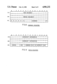
- FIG. 8 shows the data contents used in the command I/O registers of FIG. 1;
- FIG. 9 shows the data contents used in the status I/O registers of FIG. 1.
- a host computer 10 which includes a host central processor unit (CPU) 11 and a host main memory unit 12 requires communication with external I/O devices via an intermediate I/O controllerunit 13 via appropriate buses as described in more detail below.
- CPU central processor unit
- main memory unit 12 requires communication with external I/O devices via an intermediate I/O controllerunit 13 via appropriate buses as described in more detail below.
- the I/O controller unit 13 utilizes appropriate host interface units 13A which include a plurality of input and output I/O registers identified as "command" registers 14 and "status" registers 15.
- command registers 4 which receive command signalsfrom host processor 11 over a command/return bus 16 may comprise three suchregisters 14A, 14B and 14C, identified as registers DOA, DOB, and DOC.
- Return status information is then supplied in such particular embodiment on the command/return bus 16 to the host from status registers 15A, 15B and 15C, identified as registers DIA, DIB and DIC, respectively.
- incoming commands at registers 14 are appropriately processed by controller microprocessor 17 to obtain one or more control blocks of command information stored in the host main memory.
- a control block specifies, inter alia, the command operation to be executedand the location in main memory and at the external device with respect to which a data transfer is to take place.
- Controller 13 then communicates toone of a plurality of external I/O devices via suitable device interface and micro-processor logic 19 in response to such commands.
- transfers of data between the I/O devices andthe host main memory are performed via a high speed data transfer channel 20, utilizing appropriate control signals from the micro-processor 17, viahigh speed data channel bus 21. Transfers of control block information and initiation information between the controller 13 and host main memory 12 also occurs via high speed data channel 20.
- control signals can be transferred between the host processor and the I/O controller processor via dedicated lines 22-28 as described in more detailbelow.
- the I/O controller 13 is provided with access to the host main memory by the micro-processor 17 via the high speed channel 20.
- a command is received from the host CPU 11 and is placed in the command registers 14, such command can be appropriately interpreted by micro-processor 17 as requiring a sequence of one or more commands each command being part of a control block of information required to execute such command, i.e., an operation with respect to a selected external I/O device.
- Such sequence ofcontrol blocks can be pre-stored in the host main memory 12 so that when the micro-processor of the I/O controller 13 interprets a programmed I/O command from the host CPU 11, the controller successively accesses the entire sequence of control blocks from the host memory 12, fetching each block from main memory for storage in the I/O controller local memory 18 for execution before fetching the next control block of the sequence for each successive execution thereof.
- the controller is also arranged so that, during the execution of a command in one sequence, it can respond toanother subsequent programmed I/O command from the host CPU for accessing asecond sequence of control blocks, each one of which can be successively fetched for storage in local memory 18. In this way a plurality of input programmed I/O commands from the host CPU 11 can be used to generate a plurality of associated control block sequences, or lists, the control blocks of which can also be successively stored in local memory 18.
- the local memory may have stored therein a large number of separate control blocks, one from each of a plurality of separate control block lists, any one of which can be selected in accordance with a predeterminedalgorithm, for example, to be executed at any one time.
- the total number ofcommands required to be issued by the host CPU is considerably reduced and the latter can be utilized for performing other operations which it normally could not perform in a conventional I/O interface system since the host would have to use that time to issue separately each one of the large number of commands for each such command sequence in previously known systems.
- control block (command) sequences concern themselves with the transfer of information to or from the same specified I/O device
- the micro-processor 17 may utilize a predetermined algorithm for executing the commands from all of the lists involved which provides for the most effective, or optimized, movement of the I/O device access mechanism (e.g., a Read/Write head) with respect to the I/O device (e.g., a disk).
- the I/O processor may be required by the host processor to execute the commands in an established sequence in accordance with an established priority of operation thereof.
- the execution of the commands provides for a transfer of information via the high speed data channel 20 to the host memory 12 where it can be appropriately utilized by the host CPU for whatever operation it desired to perform.
- the registers 15 provide return information to the host CPU notifying the latter than such sequence has been completed and providing suitable status information concerning the state of the I/O controller 13.
- I/O controller shares memory space in main memory 12 with the host processor, such operation reduces the number of commands require fromthe host CPU when dealing with I/O devices and permits the most efficient execution of commands vis-a-vis such devices so that the overall control and data transfer operation can be optimized with respect to several programmed I/O commands from the host processor.
- control block which format is established for all control blocks, is shown in FIGS. 2 and 3.
- the control block comprises twenty words of 16 bits each, a first selected group of words including information placed therein by the host computer, a second selected group of status return words supplied in a shared mannerby the I/O controller and the host processor, and a third group of status error words supplied by the I/O controller.
- word groups are shown more specifically in FIG. 3.
- the host provides in words in words 0 and 1 a linking address (comprising a high, or most significant, portion and a low, or least significant, portion) which represents the address of the next successive control block of a sequence, or list, thereof.
- An address of zero indicates that the particular control block in question is the last one of a sequence.
- the I/O controller processor can always identify the location of the next control block of the sequence which mustbe fetched.
- Word 2 includes an optional interrupt (I) bit (bit 0) which, when set by the host processor generates an unconditional interrupt of the host by thecontroller when each control block command has been completed. If not set, the controller generates an interrupt only when a complete list or sequence of control block commands has been completed (i.e., the link address is zero) or if an error occurs.
- I optional interrupt
- Word 2 also includes a "No Retries" bit N (bit 1) which, when set by the host processor, prevents any retry for any kind of error (hard or soft) sothat, in effect, the controller treats all errors as hard errors. If N is not set, the errors are treated in accordance with the controller information block discussed below.
- Bits 6-15 of word 2 contain the operation code which identifies the operation to be performed in accordance with the following octal coding, for example:
- Words 3-6 provide main memory address (or pointers thereto) via the host memory page listings and the starting address on such page at which the data transfer will commence in main memory.
- Bit 0 (M) of word 5 when set,indicates that the address is a logical address which requires a mapping into a physical memory. If not set, the address supplied by the host is a physical address.
- Words 7 and 8 identify the address on the selected external device (e.g., the sector of a disk for the data transfer), while word 9 identifies the device, or unit, itself.
- Word 10 is shared by the host (on a command) and the I/O controller (on a return), the command identifying how much data is to be transferred (transfer count) between the selected device and the host main memory.
- the I/O controller specifies theamount of data (transfer count) that has actually been transfered.
- Word 11 is also effectively shared by host and controller.
- thehost supplies all zeroes which indicates to the controller that the host isready for the controller to execute the command involved.
- the controller supplies information concerning the completed execution of the command as follows:
- words 14-20 include information supplied by the I/O controller concerning the status of various error situations which may have arisen during the execution of the command (word 14), the status of the selected external device in this connection (word 15), the total number of error retries performed (word 16), the total amount of data (e.g., data sectors on a disk) which was transferred before an error occurred (word 17), the address of the selected device where the error occurred, e.g., a physical cylinder address on a disk (word 18) and the physical head address and physical sector address on a disk (word 19).
- Word 20 identifies a code which represents an error which has occurred with reference to the drive circuitry for the selected device (e.g., disk drive circuitry), e.g., a bus fault, a specified circuit checkpoint error,an error in the drive logic, an error in the position circuitry, a power failure, or an error in the Read/Write circuitry.
- the selected device e.g., disk drive circuitry
- each control block which is accessed by the I/O controller upon command from the host processor, provides sufficient information for the controller micro-processor to execute the command involved and to return to the host in the control block further information concerning such execution, i.e., as to whether it has been completed or whether a fault occurred to prevent the transfer of some or all of the data.
- certain initialization information is providedto the host by the controller to inform the host about the status of both the controller and units which are available for data transfer via the controller.
- Such information transfer utilizes predefined information blocks which are stored in the controller's local memory and are peculiar to the particular I/O controller involved.
- the host processor can modify the controller's operation to some extent by modifying the information in the information blocks supplied to it by the controller so that the host (i.e., the user) has some flexibility in how he wishes to handle the data transfer operation.
- the system utilizes three such information blocks as described below. Such information blocks are transferred to the host main memory, modified if desired by the host and returned to the I/O controller local memory.
- One information block can be designated as a controller information block, shown in FIG. 4 as comprising two 16-bit words.
- This block is programmableand contains device-specific information concerning the controller, in thiscase the manner in which the controller is to handle the retrying of errors(in cases where an error has occurred and the controller repeats the command execution a selected number of times to see if the error is one which is intermittent and will, when not present, permit a successful completion of the command, i.e., a "soft" error).
- Word 0 defines the maximum number of times the controller will attempt to execute a control block for a device, or unit, which is reporting an error.
- Word1 defines the maximum number of times the controller will attempt to execute a control block for an error which arises in the controller itself(bits 0-7) and the maximum number of correction retries the controller willattempt to read data with an error in the error correction code (ECC) (bits8-15).
- ECC error correction code
- the controller processor can be arranged so that a read retry is not attempted unless the controller retrycount is exceeded and the controller senses an ECC error. If during execution of a control block the maximum number of retries in this information block is exceeded in any case the type of error is indicated in the appropriate return control block words and also indicates therein the number of retries attempted, as discussed above.
- a second information block can be designated as an interface information block and contains universal information concerning a specified device which the host processor needs to know in order to handle a data transfer with respect to such device.
- the type of information in this block is the same for any device with which the controller is in communication and suchinformation cannot be modified by the host processor.
- the interface information block is shown in FIG. 5 as comprising, in a particular embodiment under discussion, seven 16-bit words.
- Word 0 contains the device type code and identifies which type of device isbeing communicated with, while word 1 contains the microcode revision number which identifies the particular instruction set which is currently executed by the I/O controller.
- Word 2 defines the highest unit number to indicate how many units are beinghandled by the controller and is fixed for any particular controller.
- Word 3 defines the total number of control blocks which can be stored in the local memory of the controller (in a particular embodiment, for example, acontroller may be capable of storing up to 30 control blocks) and is fixed for a particular controller.
- Word 3 also includes a legal count code whichdefines the type of data units which are being transferred with respect to the particular type of external device being used, e.g., data sectors for a disk device, data bytes for a tape device, etc. In a particular embodiment, for example, the legal count code may identify sectors, bytes,words or pages.
- Word 4 can be used as a masking word so as to cause an interrupt if any bits in the control block unit status word (word 15 of the control block) change.
- Word 5 defines the number of control block return status word (i.e., words 10-20 of a control block) are to be returned to the host in areturned control block, the host processor being capable of modifying this number as desired. For example, if the host specifies "0" the controller will not return any information in words 10-20 of a control block after itcompletes a control block. If the host specifies any number of words from 1to 11 and no error occurs, the controller will supply information in returncontrol block words 10 and 11 only. If an error occurs the controller will return information only for the return control block words requested by the host.
- Words 6 and 7 include masking information and contain bit 0 (word 6) which indicates, when set, that page number list addresses of a control block are two words long and, when not set, the page number list addresses are one word long.
- the remaining lists of words 6 and 7 form a 31-bit mask word which is logically ANDed with the page number list entry to produce aphysical page number.
- a further information block designated as a unit information block comprising six 16-bit words is shown in FIG. 6.
- a unit information block is available for each unit with which the controller is in communication and includes all the information, both universal and device-specific, which is needed by the host processor for handling data transfers with respect to such unit. Accordingly, the host processor cannot modify any ofthe information in the unit information block, except for information in bits 0-3 of word 0 thereof, as discussed below.
- word 0 bits 9-15
- Word 1 defines the device configuration.
- the disk configuration is defined as follows:
- Words 2 and 3 define the number of logical blocks, i.e., for a disk, the number of disk sectors, which can be accessed on the device.
- Word 4 defines the number of data bytes per logical block of the device (e.g., the number of data bytes per sector).
- word 5 defines the number of cylinders per disk, while word 6 defines both the number of heads per disk and the number of sectors per disk track. None of the values (other than bits 0-3 of word 0) can be changed.
- Bit 0 of word 0 controls the type of execution which is to be used when thecontroller has stored control blocks from more than one control block list.
- the I/O controller stores in its local memory only one control block from each of a plurality of control block lists (presuming the host processor has enqueued more than one such list).
- the controller can only execute one of such control blocksat a time, either by completing the control block of a given list which it is currently executing and then executing either the next successive control block in the same list or a currently stored control block from another list (either the next successive list or any other list that may have a control block stored in local memory).
- the I/O controller may be arranged, for example, to operate in a selected manner, which might be designated as a normal or non-optimized manner, as follows.
- the controller completes a control block of a particular list for a given external unit, if the next control block of that same list specifies the same unit, the controller executes such next control block. Otherwise, the controller executes a control block of the next successive list in the queue of lists which require execution for the same unit.
- controller may be arranged so that it enqueues a control block list behind all other lists for a specified unit (1) if a Start List command from the processor (processor commands are discussed in more detail below) requires the controller to start a new list, or (2) if a new unit is specified in the next control block of a currently executing list.
- Start List command from the processor (processor commands are discussed in more detail below) requires the controller to start a new list, or (2) if a new unit is specified in the next control block of a currently executing list.
- Such "normal" operation in effect preserves the execution order of control blocks in a list and preserves the order of the lists when more than one unit is not contained in a single list. Such operation occurs so long as the optimization bit 0 (the "O" bit) of word 0 is not set, i.e., so long as the host processor does not request optimization by setting the 0 bit.
- control blocks can execute current control blocks from any list in any desired order in accordance with any suitably selected algorithm for producing the most efficient transfer of information (e.g., movement of the Read/Write heads)with respect to a given device (e.g., on a given disk).
- a given device e.g., on a given disk.
- the controller does not have to complete one list before starting the next. Instead, it may skip from list to list and execute control blocks for the same unit from different control block lists in accordance with a suitableselected and predefined algorithm. In any event, the order of control blocks within a list is preserved.
- Bit S (bit 1 of word 0) represents an error interrupt bit. If set by the host, the controller must interrupt the host on any error which occurs during the execution of a control block. If not set, an interrupt occurs only when all the retry counts in the controller information block have been exhausted and the error is then "hard".
- Bit M (bit 2 of word 0) represents a modified bit which, when set by the host, informs the controller that the host has modified the information ofa sector of the disk on a write operation. If not set a write operation clears the modified bit.
- the A bit (bit 3 of word 0) is used when an external unit has dual ports permitting two controllers to access the same unit. For such units three operations can occur: (1) a "reserve” operation in which a device is reserved for exclusive use by one controller via one port (another controller cannot even use the other port); (2) a “release” operation which frees a device from exclusive use by a controller so that a second controller can use the unit through the other port (the unit is automatically released by a controller after each use); and (3) a "trespass” operation which overrides a controller's exclusive use of a unit at any time, e.g., a second controller can override, via a second port, a first controller which has currently reserved use for the unit viathe first port.
- Such operations are controlled through use of the A bit in conjunction with the 0 bit as follows.
- a controller reserves a unit before executing a control block and keeps the unit reserved so long as current control blocks specify such unit. When the current control blocks no longer specifiy that unit the controller releases the reserved unit.
- a controller reserves a unit before executing a control block but immediately release it after execution. If this condition is set for two controllers using the same unit, for example, the controllers in effect alternate their use of the unit.
- a controller reserves a unit before executing a control block and after execution checks the control block optimization queue for that drive. If further control blocksare awaiting execution for such unit the controller executes the next control block in the queue and does not release the unit until all such control blocks in the queue are executed.
- the "trespass" condition only occurs for a programmed I/O command therefor issued by the host processor as discussed with reference to programmed I/Ocommands below. Such a command is normally rarely used but can be issued, for example, if a user requires immediate access to a unit.
- an extended status information block can be stored by the controller in its local memory. If an error occurs the error can usually be resolved using the error status information provided in the status registers (discussed below) or in the control block error status words. However, if the error is severe (effectively not resolvable using such information) it may be necessary to supply additional (extended) information to the host concerning the error status, such information being supplied by generating an extended status information block of thirty-two 16-bit words, as shown in FIG. 7.
- the words generally contain information as follows:
- An extended status information block is maintained for each unit accessed by the controller and provides status information for each error which occurs (when the S bit of the unit information block is set the status information at the time such error occurred is contained in the extended status block while if the S bit is not set the extended status block reflects the last error that occurred).
- the host can retrieve the extendedstatus block for a particular unit from the controller's local memory by issuing the appropriate command therefor as discussed below. After storingan extended status block in main memory the host must issue a re-start command to begin execution again, also as discussed below.
- the commands utilized by the host processor and supplied from the host accumulators to the command registers 14 comprise a programmed I/O (PIO) command set for controlling the operation of the controller and the transfer of control blocks and information blocks.
- PIO programmed I/O
- Such commands are issued by the host in response to appropriate assembler I/O instructions utilized by the host in accordance with the operation of the host processor.
- the host processor may be a processor of the type made and sold by Data General Corporation under the designation Eclipse®, one such model thereof being the MV-8000® model which iscurrently available to those in the art and which includes suitable I/O instructions.
- Eclipse® Data General Corporation
- Other processors available to the art can be used by those in the art and their use in the context described would be within the skills of those in the art from the description presented here.
- control blocks form a command set for the external device drive interface, e.g., a set of disk commands.
- the controlblocks are loaded with a device command operation code and the control block is executed by issuing a PIO command from the host processor via an assembler I/O instruction which decodes the assembler instruction to produce the required PIO command.
- the controller responds to the PIO commands via the controller registers, i.e., the command registers 14 (DOA, DOB and DOC), and the return status registers 15 (DIA, DIB and DIC), each containing a 16-bit word in the particular embodiment disclosed.
- the assembler instructions transfer information between host accumulators and the controller registers 14 and 15, i.e., PIO commands from the host to registers 14 and status and interrupt information from registers 15 to host.
- FIG. 8 depicts the format of PIO commands issued to command registers DOA, DOB and DOC.
- the registers 14A and 14B contain the commandarguments while register 15C contains the PIO command code and a return bit(the unused bits are all 0's).
- register A contains the high order word (most significant bits) and register B the low order word (least significant bits).
- the returnbit R determined whether the controller will generate a synchronous interrupt when the PIO command has been completed (R is set) or whether such interrupt is not generated (R is not set).
- the command registers can be loaded in any order so long as the controller' "busy" flag (on line 26)is clear (not set). The execution of the PIO command will not begin until the host issues a start S-pulse on line 24.
- the I/O controller loads interrupt return information into status registers15.
- Interrupts in the system described can be asynchronous or synchronous in nature, the former occurring after a control block error or when the controller completes its execution of a control block and the latter occurring when the controller completes a PIO command.
- FIG. 9 depicts the return information format in registers 15 wherein registers 15A and 15B contain interrupt information and register 15C contains status information ("status") concerning the command state, further command completion status bits (“CCS") indicating the type of interrupt and either the original command code and return request bit (as originally loaded into bits 6-15 of register 14C) if a synchronous interrupt occurs or interrupt code if an asynchronous interrupt occurred.
- the status bits 0-3 are valid only when the "Busy” flag is clear, while the remaining bits of all the registers are valid only when the "Done" flag is set.
- the Busy and Done flags indicate whether the I/O controller is performing an operation or whether it has completed one and their settings can be checked before issuing a PIO command.
- the Busy flag is set as soon as the host issues an S-pulse and remains set until execution of the entire PIO command is completed so that no further PIO commands can be issued to registers 14 until the Busy flag is clear.
- the Done flag whether set for an asynchronous or a synchronous interrupt, indicates that the status registers 15 contain valid return information. Selected bits of the I/O assembler instruction are used to control selected functions of the I/O controller via the pulse signals on dedicated lines 22-25.
- the R-pulse resets all internal I/O controller logic, clears the Busy and Done flags and all pending interrupt requests.
- the S-pulse starts a PIO command, thereby setting the Busy flag and clearing the Done flag.
- the C-pulse services an interrupt and clears the Done flag and the pending interrupt.
- the P-pulse sets an internal controller state that causes an Interrupt (Line 28) to be generated when the controller goes Not Busy if the Done flag is clear.
- Appendix A shows a table of exemplary PIO commands which can be issued by the host processor and supplied to registers 14 the contents of each such register being listed therein for each such command.
- the specific encodings of the registers, and particularly the DOC register 15C, are exemplary only for use in a particular embodiment of the invention and illustrate typical encodings.
- command operating codes in the register 15C can be as follows:
- the I/O controller loads its status registers 15 with the command return information and setsthe Done flag when the Busy flag clears if the return request bit R is set.If the latter is not set the status registers are not loaded nor is the Done flag set. Setting the Done flag generates an interrupt request to thehost.
- the controller loads error return information into the status registers 15 and sets the Done flag regardlessof whether the return request bit is set.
- the registers 15 transfer their contents to specified host accumulators so that the host can determined interrupt recovery procedures.
- the host interrupt routine services such interrupt by issuing a C-pulse.
- Selected bits (bits 4-5) of the status register 15C indicate whether the interrupt is asynchronous or synchronous while other selected bits (bits 6-15) are coded to indicate the kind of error which occurred. If a synchronous interrupt occurs such bits merely "echo" the original command code and return request bit setting of the most recent command sent to thecontroller.
- the status bits 0-3 of register 15C are valid whenever Busy is clear, while the remaining bits thereof are valid whenever the Done flag is set. Additional return information can be transferred via registers 15Aand 15B. Whenever such information represents an address, register 15A contains the higher order bits and register 15B the lower order bits. Suchregister contents are valid when the Done flag is set.
- the table of Appendix B lists different types of exemplary asynchronous interrupts while the table of Appendix C lists different types of exemplary synchronous interrupts and both tables describe the contents of registers 15 in each case for a particular embodiment of the invention.
- the controller completion status determined by bits 4-5 of register 15C identifies the following exemplary types of interruptions.
- Exemplary types of asynchronous interrupt error codes as used in bits 6-15 of status register 15C are identified as follows:
- the controller Upon the occurrence of an error identified by the error code the controllerutilizes an appropriately predetermined interrupt routine with respect thereto.
- Initialization commands can be used to transfer different use options available to the system during operation, such as address mapping, interface, controller and device (unit) operations.
- Diagnostic commands are used to perform selected diagnostic tests on the controller in the event of controller errors.
- Extended status commands areused to examine the state of the device subsystem when an error occurs.
- List control commands are used to perform control block operations. State independent commands can be used to initiate the diagnostic command set orto reset the controller.
- Valid While Reset commands can be used to move initial Load Programs into the host main memory or to cause the controllerto load its microcode control store.
- the host may be a Data General Corporation MV-8000® system while the controller micro-processor may be of the type made and sold by Data General Corporation under the the designations Micro-NOVA® or Micro-Eclipse® microprocessors.
- the high speed data transfer channel may be of the type described in U.S. Pat. No. 4,403,282, issued Sept. 6, 1983 now allowed but not yet issued, a high speed data transfer channel often referred to as a "burst multiplex channel" as used, for example, andavailable in Data General Corporation's M-600 data processing system.
Abstract
A data processing system which includes a host processor and an input/output (I/O) controller unit for controlling communication with I/O devices. The controller processor receives I/O commands from the host processor, accesses and stores control block lists of control commands associated with such I/O commands, and executes the control commands from such control block lists. The controller unit stores controller information concerning the operational capability of the controller unit and the host processor is capable of accessing such controller information and in turn can modify such operational capability if desired.
Description
This is a continuation of co-pending application Ser. No. 496,125 filed on May 19, 1983, now abandoned.
This invention relates generally to data processing systems and, more particularly, to a unique interface control system for providing communication between a host computer processor and an input/output control processor which in turn is in communication with external or peripheral devices.
In order to provide communication between a host computer and a plurality of external input/output (I/O) units, or devices, such as disks, tapes, printers, display devices, etc., it is effective for data processing systems to utilize an intermediate control processor which communicates with the host computer processor and in turn communicates with a large number of I/O devices. Control of which devices require the transfer of data to and from the host computer then residues in the intermediate I/O controller.
In most conventional systems utilizing such approach the host processor supplies an appropriate command to an I/O controller processor which in turn interprets such commands so that the I/O device required can be identified and the appropriate data processing and transfer operation can occur. The host normally supplies such command in sequence and the I/O processor processes such commands in such sequence. If the I/O processor is busy with a particular command requiring the servicing of a specified I/O device the host must wait until that process has been completed before it can issue subsequent commands related either to the same or to a different I/O device. Such an approach normally requires the transfer of a relatively large number of commands from the host processor and does not permit the controller to make the most effective use of a sequence of such commands. For example, if the host processor desires to access blocks of data from, or to store blocks of data on, an I/O device such as a disk, for example, such data blocks may reside at various locations on the disk and the Read/Write head which accesses the device must move from one location to the other in accordance with the particular command received by the I/O controller. Since in many cases the sequence of movements of the head on a particular disk required for a specific sequence of commands may not represent the most efficient movement for transferring all of the data required by such sequence, it is desirable to establish a more effective manner for controlling the data transfer to or from the same I/O device in an optimized fashion.
It is further desirable to arrange for the I/O controller to operate in response to a reduced number of commands from the host processor so that the host processor can transfer the desired information with the least amount of host processor time and with reduced I/O communication overhead so that the host processor can perform other tasks in the meanwhile.
The system in accordance with the invention utilizes an I/O controller which is capable of receiving a single command from the host processor, which command can then be utilized to generate in turn an entire block or list of sequential commands which are pre-stored in the host's main memory, such memory thereby being effectively shared by both the host processor and the I/O controller. The host then need only supply a single host programmed I/O command to generate a a relatively large number of sequential controller I/O commands associated therewith in order to perform any particular overall data transfer, rather than having the host processor supply an entire sequence of such commands for that particular data transfer operation.
Further, the I/O controller is arranged in accordance with the invention so that it can respond to several successive host processor programmed I/O commands and in turn generate several corresponding blocks or lists of command sequences, appropriate commands of each sequence beng stored in the I/O controller local memory at any one time for suitable execution. The I/O controller can then execute such command lists in accordance with a suitably selected procedure as desired. Thus, the I/O controller may be controlled to provide a selected sequence of command list execution in which a complete command list is executed before a next successive complete command list is executed. Alternatively, an I/O controller may be arranged to select a more efficient procedure in which commands from several different command lists can be executed in any desired optimized order, i.e., an order in which commands can be selected from any of the command lists so that data transfers to and from the same I/O device can be most efficiently executed. Alternatively, either of such procedures may further be arranged to take into account appropriate priorities which may be established for such command lists by the host processor, for example, and perform such command lists in accordance with the established priorities.
Further, the I/O controller can be arranged to permit the host processor to utilize initialization commands independently of the programmed I/O commands, so as to cause the controller to operate in a selected one of a number of different ways as desired by the user, for example, with respect to the treatment of errors, the selection of the type of status information required by the host processor, the selection of which process to use then transferring information to or from a particular I/O device in accordance with a sequence of commands, and the like.
The invention can be described in more detail with the help of the accompanying drawings wherein
FIG. 1 shows a block diagram of a system in accordance with the invention;
FIG. 2 shows a general data format of the contents of an exemplary control block of data used in the system of FIG. 1;
FIG. 3 shows a more specific data format of the control block of FIG. 2;
FIG. 4 shows a data format of the contents of a controller information block of data used by an I/O controller in the system of FIG. 1;
FIG. 5 shows a data format of the contents of an interface information block of data used by the I/O controller of FIG. 1;
FIG. 6 shows a data format of the contents of a unit information block of data used by the I/O controller of FIG. 1;
FIG. 7 shows a data format of the contents of an extended status information block of data used in the system of FIG. 1;
FIG. 8 shows the data contents used in the command I/O registers of FIG. 1; and
FIG. 9 shows the data contents used in the status I/O registers of FIG. 1.
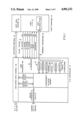
As can be seen in FIG. 1, a host computer 10 which includes a host central processor unit (CPU) 11 and a host main memory unit 12 requires communication with external I/O devices via an intermediate I/O controllerunit 13 via appropriate buses as described in more detail below.
The I/O controller unit 13 utilizes appropriate host interface units 13A which include a plurality of input and output I/O registers identified as "command" registers 14 and "status" registers 15. In a particular embodiment, for example, command registers 4 which receive command signalsfrom host processor 11 over a command/return bus 16 may comprise three suchregisters 14A, 14B and 14C, identified as registers DOA, DOB, and DOC. Return status information is then supplied in such particular embodiment on the command/return bus 16 to the host from status registers 15A, 15B and 15C, identified as registers DIA, DIB and DIC, respectively. As discussed in more detail below, incoming commands at registers 14 are appropriately processed by controller microprocessor 17 to obtain one or more control blocks of command information stored in the host main memory.A control block specifies, inter alia, the command operation to be executedand the location in main memory and at the external device with respect to which a data transfer is to take place. Controller 13 then communicates toone of a plurality of external I/O devices via suitable device interface and micro-processor logic 19 in response to such commands. In the particular system disclosed, transfers of data between the I/O devices andthe host main memory are performed via a high speed data transfer channel 20, utilizing appropriate control signals from the micro-processor 17, viahigh speed data channel bus 21. Transfers of control block information and initiation information between the controller 13 and host main memory 12 also occurs via high speed data channel 20.
In addition to various host programmed I/O commands and controller return information which are transferred on bi-directional bus 16, further control signals can be transferred between the host processor and the I/O controller processor via dedicated lines 22-28 as described in more detailbelow.
Before discussing the control signal which are utilized by the I/O controller/host interface 13A it is desirable to discuss generally the advantages of utilizing the configuration of the invention as generally disclosed in the embodiment of FIG. 1.
The I/O controller 13 is provided with access to the host main memory by the micro-processor 17 via the high speed channel 20. When a command is received from the host CPU 11 and is placed in the command registers 14, such command can be appropriately interpreted by micro-processor 17 as requiring a sequence of one or more commands each command being part of a control block of information required to execute such command, i.e., an operation with respect to a selected external I/O device. Such sequence ofcontrol blocks can be pre-stored in the host main memory 12 so that when the micro-processor of the I/O controller 13 interprets a programmed I/O command from the host CPU 11, the controller successively accesses the entire sequence of control blocks from the host memory 12, fetching each block from main memory for storage in the I/O controller local memory 18 for execution before fetching the next control block of the sequence for each successive execution thereof. The controller is also arranged so that, during the execution of a command in one sequence, it can respond toanother subsequent programmed I/O command from the host CPU for accessing asecond sequence of control blocks, each one of which can be successively fetched for storage in local memory 18. In this way a plurality of input programmed I/O commands from the host CPU 11 can be used to generate a plurality of associated control block sequences, or lists, the control blocks of which can also be successively stored in local memory 18.
Thus, the local memory may have stored therein a large number of separate control blocks, one from each of a plurality of separate control block lists, any one of which can be selected in accordance with a predeterminedalgorithm, for example, to be executed at any one time. The total number ofcommands required to be issued by the host CPU is considerably reduced and the latter can be utilized for performing other operations which it normally could not perform in a conventional I/O interface system since the host would have to use that time to issue separately each one of the large number of commands for each such command sequence in previously known systems.
For example, in some cases where more than one of the control block (command) sequences (lists) concern themselves with the transfer of information to or from the same specified I/O device, it may be desirable to assure that such data transfers occur in the most efficient manner. In such a case it may be desirable for the micro-processor 17 to utilize a predetermined algorithm for executing the commands from all of the lists involved which provides for the most effective, or optimized, movement of the I/O device access mechanism (e.g., a Read/Write head) with respect to the I/O device (e.g., a disk).
Alternatively, the I/O processor may be required by the host processor to execute the commands in an established sequence in accordance with an established priority of operation thereof. In any event, the execution of the commands provides for a transfer of information via the high speed data channel 20 to the host memory 12 where it can be appropriately utilized by the host CPU for whatever operation it desired to perform. Once a complete sequence of commands from any control block list has been performed, the registers 15 provide return information to the host CPU notifying the latter than such sequence has been completed and providing suitable status information concerning the state of the I/O controller 13.
Because the I/O controller shares memory space in main memory 12 with the host processor, such operation reduces the number of commands require fromthe host CPU when dealing with I/O devices and permits the most efficient execution of commands vis-a-vis such devices so that the overall control and data transfer operation can be optimized with respect to several programmed I/O commands from the host processor.
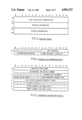
In order to better understand such operation, the format of a control block, which format is established for all control blocks, is shown in FIGS. 2 and 3. As seen in FIG. 2, in a particular embodiment thereof, the control block comprises twenty words of 16 bits each, a first selected group of words including information placed therein by the host computer, a second selected group of status return words supplied in a shared mannerby the I/O controller and the host processor, and a third group of status error words supplied by the I/O controller. Such word groups are shown more specifically in FIG. 3.
As can be seen in FIG. 3, the host provides in words in words 0 and 1 a linking address (comprising a high, or most significant, portion and a low, or least significant, portion) which represents the address of the next successive control block of a sequence, or list, thereof. An address of zero indicates that the particular control block in question is the last one of a sequence. Thus, the I/O controller processor can always identify the location of the next control block of the sequence which mustbe fetched.
Word 2 includes an optional interrupt (I) bit (bit 0) which, when set by the host processor generates an unconditional interrupt of the host by thecontroller when each control block command has been completed. If not set, the controller generates an interrupt only when a complete list or sequence of control block commands has been completed (i.e., the link address is zero) or if an error occurs.
Word 2 also includes a "No Retries" bit N (bit 1) which, when set by the host processor, prevents any retry for any kind of error (hard or soft) sothat, in effect, the controller treats all errors as hard errors. If N is not set, the errors are treated in accordance with the controller information block discussed below.
Bits 6-15 of word 2 contain the operation code which identifies the operation to be performed in accordance with the following octal coding, for example:
______________________________________
Octal Code     Meaning
______________________________________
000            No Operation
100            Write
101            Write/Verify
104            Write Single Word
105            Write/Verify Single Word
142            Write with Modified Bit Map
200            Read
201            Read/Verify
205            Read/Verify Single Word
210            Read Raw Data
220            Read Headers
242            Read with Modified Bit Map
400            Recalibrate Disk
______________________________________
Words 3-6 provide main memory address (or pointers thereto) via the host memory page listings and the starting address on such page at which the data transfer will commence in main memory. Bit 0 (M) of word 5, when set,indicates that the address is a logical address which requires a mapping into a physical memory. If not set, the address supplied by the host is a physical address.
Words 7 and 8 identify the address on the selected external device (e.g., the sector of a disk for the data transfer), while word 9 identifies the device, or unit, itself.
Word 10 is shared by the host (on a command) and the I/O controller (on a return), the command identifying how much data is to be transferred (transfer count) between the selected device and the host main memory. When the transfer has been completed the I/O controller then specifies theamount of data (transfer count) that has actually been transfered.
Word 11 is also effectively shared by host and controller. On a command thehost supplies all zeroes which indicates to the controller that the host isready for the controller to execute the command involved. On a return the controller supplies information concerning the completed execution of the command as follows:
______________________________________
Bit    Meaning if set:
______________________________________
0      Any CB hard execution error
1      Interpretation error
2      Soft errors in execution occurred; controller recovered
3      CB termination by Cancel List command
4      ECC correction needed
5      ECC correction failed
6-14   Unused
15     CB Done bit
______________________________________
Although words 12 and 13 in the embodiment under discussion are reserved for future use, words 14-20 include information supplied by the I/O controller concerning the status of various error situations which may have arisen during the execution of the command (word 14), the status of the selected external device in this connection (word 15), the total number of error retries performed (word 16), the total amount of data (e.g., data sectors on a disk) which was transferred before an error occurred (word 17), the address of the selected device where the error occurred, e.g., a physical cylinder address on a disk (word 18) and the physical head address and physical sector address on a disk (word 19). Word 20 identifies a code which represents an error which has occurred with reference to the drive circuitry for the selected device (e.g., disk drive circuitry), e.g., a bus fault, a specified circuit checkpoint error,an error in the drive logic, an error in the position circuitry, a power failure, or an error in the Read/Write circuitry.
Accordingly, each control block, which is accessed by the I/O controller upon command from the host processor, provides sufficient information for the controller micro-processor to execute the command involved and to return to the host in the control block further information concerning such execution, i.e., as to whether it has been completed or whether a fault occurred to prevent the transfer of some or all of the data.
Before transferring one or more control blocks from the host main memory tothe I/O controller so that the commands involved can be executed by the controller micro-processor, certain initialization information is providedto the host by the controller to inform the host about the status of both the controller and units which are available for data transfer via the controller. Such information transfer utilizes predefined information blocks which are stored in the controller's local memory and are peculiar to the particular I/O controller involved. Once the host processor is so informed about the particular I/O controller with which it is communicating, the host can modify the controller's operation to some extent by modifying the information in the information blocks supplied to it by the controller so that the host (i.e., the user) has some flexibility in how he wishes to handle the data transfer operation. In theparticular embodiment being described the system utilizes three such information blocks as described below. Such information blocks are transferred to the host main memory, modified if desired by the host and returned to the I/O controller local memory.
One information block can be designated as a controller information block, shown in FIG. 4 as comprising two 16-bit words. This block is programmableand contains device-specific information concerning the controller, in thiscase the manner in which the controller is to handle the retrying of errors(in cases where an error has occurred and the controller repeats the command execution a selected number of times to see if the error is one which is intermittent and will, when not present, permit a successful completion of the command, i.e., a "soft" error). Word 0 defines the maximum number of times the controller will attempt to execute a control block for a device, or unit, which is reporting an error. In all cases thewords are all zeroes at power up and the controller microcode is arranged to set the information in the information blocks following power up.) Word1 defines the maximum number of times the controller will attempt to execute a control block for an error which arises in the controller itself(bits 0-7) and the maximum number of correction retries the controller willattempt to read data with an error in the error correction code (ECC) (bits8-15). For example, in the latter cases the controller processor can be arranged so that a read retry is not attempted unless the controller retrycount is exceeded and the controller senses an ECC error. If during execution of a control block the maximum number of retries in this information block is exceeded in any case the type of error is indicated in the appropriate return control block words and also indicates therein the number of retries attempted, as discussed above.
A second information block can be designated as an interface information block and contains universal information concerning a specified device which the host processor needs to know in order to handle a data transfer with respect to such device. The type of information in this block is the same for any device with which the controller is in communication and suchinformation cannot be modified by the host processor. The interface information block is shown in FIG. 5 as comprising, in a particular embodiment under discussion, seven 16-bit words.
Word 0 contains the device type code and identifies which type of device isbeing communicated with, while word 1 contains the microcode revision number which identifies the particular instruction set which is currently executed by the I/O controller.
Word 2 defines the highest unit number to indicate how many units are beinghandled by the controller and is fixed for any particular controller. Word 3 defines the total number of control blocks which can be stored in the local memory of the controller (in a particular embodiment, for example, acontroller may be capable of storing up to 30 control blocks) and is fixed for a particular controller. Word 3 also includes a legal count code whichdefines the type of data units which are being transferred with respect to the particular type of external device being used, e.g., data sectors for a disk device, data bytes for a tape device, etc. In a particular embodiment, for example, the legal count code may identify sectors, bytes,words or pages.
Word 4 can be used as a masking word so as to cause an interrupt if any bits in the control block unit status word (word 15 of the control block) change. Word 5 defines the number of control block return status word (i.e., words 10-20 of a control block) are to be returned to the host in areturned control block, the host processor being capable of modifying this number as desired. For example, if the host specifies "0" the controller will not return any information in words 10-20 of a control block after itcompletes a control block. If the host specifies any number of words from 1to 11 and no error occurs, the controller will supply information in returncontrol block words 10 and 11 only. If an error occurs the controller will return information only for the return control block words requested by the host.
Words 6 and 7 include masking information and contain bit 0 (word 6) which indicates, when set, that page number list addresses of a control block are two words long and, when not set, the page number list addresses are one word long. The remaining lists of words 6 and 7 form a 31-bit mask word which is logically ANDed with the page number list entry to produce aphysical page number.
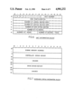
A further information block designated as a unit information block comprising six 16-bit words is shown in FIG. 6. A unit information block is available for each unit with which the controller is in communication and includes all the information, both universal and device-specific, which is needed by the host processor for handling data transfers with respect to such unit. Accordingly, the host processor cannot modify any ofthe information in the unit information block, except for information in bits 0-3 of word 0 thereof, as discussed below.
Before discussing the latter bits, it can be seen that word 0 (bits 9-15) is used to identify the external unit involved (as in word 9 of the control block). Word 1 defines the device configuration. Thus, when the unit is a disk, for example, the disk configuration is defined as follows:
______________________________________
Bit             Meaning if set:
______________________________________
0               Moving Heads
1               Fixed Heads
2               Fixed/Removable Media
3               Dual Ported
4-15            Unspecified
______________________________________
Words 2 and 3 define the number of logical blocks, i.e., for a disk, the number of disk sectors, which can be accessed on the device. Word 4 defines the number of data bytes per logical block of the device (e.g., the number of data bytes per sector). For a disk, word 5 defines the number of cylinders per disk, while word 6 defines both the number of heads per disk and the number of sectors per disk track. None of the values (other than bits 0-3 of word 0) can be changed.
Bit 0 of word 0 controls the type of execution which is to be used when thecontroller has stored control blocks from more than one control block list.In order to understand such operation the manner in which the controller handles control blocks should be understood. The I/O controller stores in its local memory only one control block from each of a plurality of control block lists (presuming the host processor has enqueued more than one such list). The controller can only execute one of such control blocksat a time, either by completing the control block of a given list which it is currently executing and then executing either the next successive control block in the same list or a currently stored control block from another list (either the next successive list or any other list that may have a control block stored in local memory).
With that in mind, the I/O controller may be arranged, for example, to operate in a selected manner, which might be designated as a normal or non-optimized manner, as follows. When the controller completes a control block of a particular list for a given external unit, if the next control block of that same list specifies the same unit, the controller executes such next control block. Otherwise, the controller executes a control block of the next successive list in the queue of lists which require execution for the same unit. Further the controller may be arranged so that it enqueues a control block list behind all other lists for a specified unit (1) if a Start List command from the processor (processor commands are discussed in more detail below) requires the controller to start a new list, or (2) if a new unit is specified in the next control block of a currently executing list. Such "normal" operation in effect preserves the execution order of control blocks in a list and preserves the order of the lists when more than one unit is not contained in a single list. Such operation occurs so long as the optimization bit 0 (the "O" bit) of word 0 is not set, i.e., so long as the host processor does not request optimization by setting the 0 bit.
If the "0" bit is set, optimization is enabled and the controller can execute current control blocks from any list in any desired order in accordance with any suitably selected algorithm for producing the most efficient transfer of information (e.g., movement of the Read/Write heads)with respect to a given device (e.g., on a given disk). Thus, if five control block lists each control control blocks for the same unit the controller does not have to complete one list before starting the next. Instead, it may skip from list to list and execute control blocks for the same unit from different control block lists in accordance with a suitableselected and predefined algorithm. In any event, the order of control blocks within a list is preserved.
Bit S (bit 1 of word 0) represents an error interrupt bit. If set by the host, the controller must interrupt the host on any error which occurs during the execution of a control block. If not set, an interrupt occurs only when all the retry counts in the controller information block have been exhausted and the error is then "hard".
Bit M (bit 2 of word 0) represents a modified bit which, when set by the host, informs the controller that the host has modified the information ofa sector of the disk on a write operation. If not set a write operation clears the modified bit.
The A bit (bit 3 of word 0) is used when an external unit has dual ports permitting two controllers to access the same unit. For such units three operations can occur: (1) a "reserve" operation in which a device is reserved for exclusive use by one controller via one port (another controller cannot even use the other port); (2) a "release" operation which frees a device from exclusive use by a controller so that a second controller can use the unit through the other port (the unit is automatically released by a controller after each use); and (3) a "trespass" operation which overrides a controller's exclusive use of a unit at any time, e.g., a second controller can override, via a second port, a first controller which has currently reserved use for the unit viathe first port. Such operations are controlled through use of the A bit in conjunction with the 0 bit as follows.
When the A bit is not set (the O bit is a "don't care") a controller reserves a unit before executing a control block and keeps the unit reserved so long as current control blocks specify such unit. When the current control blocks no longer specifiy that unit the controller releases the reserved unit.
When the A bit is set and the O bit is not set, a controller reserves a unit before executing a control block but immediately release it after execution. If this condition is set for two controllers using the same unit, for example, the controllers in effect alternate their use of the unit.
When the A bit is set and the O bit is also set, a controller reserves a unit before executing a control block and after execution checks the control block optimization queue for that drive. If further control blocksare awaiting execution for such unit the controller executes the next control block in the queue and does not release the unit until all such control blocks in the queue are executed.
The "trespass" condition only occurs for a programmed I/O command therefor issued by the host processor as discussed with reference to programmed I/Ocommands below. Such a command is normally rarely used but can be issued, for example, if a user requires immediate access to a unit.
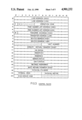
In addition to control blocks and initiation information blocks discussed above, an extended status information block can be stored by the controller in its local memory. If an error occurs the error can usually be resolved using the error status information provided in the status registers (discussed below) or in the control block error status words. However, if the error is severe (effectively not resolvable using such information) it may be necessary to supply additional (extended) information to the host concerning the error status, such information being supplied by generating an extended status information block of thirty-two 16-bit words, as shown in FIG. 7. The words generally contain information as follows:
______________________________________
Words Block Name   Contents
______________________________________
0-1   Ending Memory
                   Control information and the high
      Address      speed channel
 2-18 Controller   A dump of the controller's registers.
      Error Report This dump contains disk information
                   generated before and after an error.
19-23 --           Unused; all zeros.
24-29 Drive Error  An error code and drive status
      Report       information.
30-31 --           Unused; all zeros.
______________________________________
An extended status information block is maintained for each unit accessed by the controller and provides status information for each error which occurs (when the S bit of the unit information block is set the status information at the time such error occurred is contained in the extended status block while if the S bit is not set the extended status block reflects the last error that occurred). The host can retrieve the extendedstatus block for a particular unit from the controller's local memory by issuing the appropriate command therefor as discussed below. After storingan extended status block in main memory the host must issue a re-start command to begin execution again, also as discussed below.
The commands utilized by the host processor and supplied from the host accumulators to the command registers 14 comprise a programmed I/O (PIO) command set for controlling the operation of the controller and the transfer of control blocks and information blocks. Such commands are issued by the host in response to appropriate assembler I/O instructions utilized by the host in accordance with the operation of the host processor. for example, the host processor may be a processor of the type made and sold by Data General Corporation under the designation Eclipse®, one such model thereof being the MV-8000® model which iscurrently available to those in the art and which includes suitable I/O instructions. Other processors available to the art can be used by those in the art and their use in the context described would be within the skills of those in the art from the description presented here. In this context, control blocks, as described above, form a command set for the external device drive interface, e.g., a set of disk commands. The controlblocks are loaded with a device command operation code and the control block is executed by issuing a PIO command from the host processor via an assembler I/O instruction which decodes the assembler instruction to produce the required PIO command.
The controller responds to the PIO commands via the controller registers, i.e., the command registers 14 (DOA, DOB and DOC), and the return status registers 15 (DIA, DIB and DIC), each containing a 16-bit word in the particular embodiment disclosed. The assembler instructions transfer information between host accumulators and the controller registers 14 and 15, i.e., PIO commands from the host to registers 14 and status and interrupt information from registers 15 to host.
FIG. 8 depicts the format of PIO commands issued to command registers DOA, DOB and DOC. As can be seen, the registers 14A and 14B contain the commandarguments while register 15C contains the PIO command code and a return bit(the unused bits are all 0's). If the arguments are addresses (as is usually the case, for example, when the command requires the I/O controller to fetch a control block at a specified location in main memory) register A contains the high order word (most significant bits) and register B the low order word (least significant bits). A selected bit(e.g., bit 0) of register 14A can be used to indicate whether the address is a physical address (bit 0=0) or a logical address (bit 0=1). The returnbit R determined whether the controller will generate a synchronous interrupt when the PIO command has been completed (R is set) or whether such interrupt is not generated (R is not set). The command registers can be loaded in any order so long as the controller' "busy" flag (on line 26)is clear (not set). The execution of the PIO command will not begin until the host issues a start S-pulse on line 24.
The I/O controller loads interrupt return information into status registers15. Interrupts in the system described can be asynchronous or synchronous in nature, the former occurring after a control block error or when the controller completes its execution of a control block and the latter occurring when the controller completes a PIO command.
FIG. 9 depicts the return information format in registers 15 wherein registers 15A and 15B contain interrupt information and register 15C contains status information ("status") concerning the command state, further command completion status bits ("CCS") indicating the type of interrupt and either the original command code and return request bit (as originally loaded into bits 6-15 of register 14C) if a synchronous interrupt occurs or interrupt code if an asynchronous interrupt occurred. The status bits 0-3 are valid only when the "Busy" flag is clear, while the remaining bits of all the registers are valid only when the "Done" flag is set.
The Busy and Done flags indicate whether the I/O controller is performing an operation or whether it has completed one and their settings can be checked before issuing a PIO command. The Busy flag is set as soon as the host issues an S-pulse and remains set until execution of the entire PIO command is completed so that no further PIO commands can be issued to registers 14 until the Busy flag is clear. The Done flag, whether set for an asynchronous or a synchronous interrupt, indicates that the status registers 15 contain valid return information. Selected bits of the I/O assembler instruction are used to control selected functions of the I/O controller via the pulse signals on dedicated lines 22-25. The R-pulse resets all internal I/O controller logic, clears the Busy and Done flags and all pending interrupt requests. The S-pulse starts a PIO command, thereby setting the Busy flag and clearing the Done flag. The C-pulse services an interrupt and clears the Done flag and the pending interrupt. The P-pulse sets an internal controller state that causes an Interrupt (Line 28) to be generated when the controller goes Not Busy if the Done flag is clear.
Appendix A shows a table of exemplary PIO commands which can be issued by the host processor and supplied to registers 14 the contents of each such register being listed therein for each such command. The specific encodings of the registers, and particularly the DOC register 15C, are exemplary only for use in a particular embodiment of the invention and illustrate typical encodings.
For example, command operating codes in the register 15C can be as follows:
______________________________________
Code          Command Name
______________________________________
000           Program Load
002           Begin
024           Diagnostic Mode (Enter/Exit)
026           Set Mapping Information
027           Get Mapping Information
030           Set Interface Information
031           Get Interface Information
032           Set Controller Information
033           Get Controller Information
034           Set Unit Information
035           Get Unit Information
040           Get Extended Status 0
041           Get Extended Status 1
042           Get Extended Status 2
043           Get Extended Status 3
100           Start List
103           Start List (High Priority)
116           Restart
123           Cancel List
131           Unit Status
132           Trespass
133           Get List Status
777           Reset
______________________________________
When the particular PIO command is completely executed the I/O controller loads its status registers 15 with the command return information and setsthe Done flag when the Busy flag clears if the return request bit R is set.If the latter is not set the status registers are not loaded nor is the Done flag set. Setting the Done flag generates an interrupt request to thehost.
If the PIO command results in an error, the controller loads error return information into the status registers 15 and sets the Done flag regardlessof whether the return request bit is set. The registers 15 transfer their contents to specified host accumulators so that the host can determined interrupt recovery procedures. The host interrupt routine services such interrupt by issuing a C-pulse.
Selected bits (bits 4-5) of the status register 15C indicate whether the interrupt is asynchronous or synchronous while other selected bits (bits 6-15) are coded to indicate the kind of error which occurred. If a synchronous interrupt occurs such bits merely "echo" the original command code and return request bit setting of the most recent command sent to thecontroller. The status bits 0-3 of register 15C are valid whenever Busy is clear, while the remaining bits thereof are valid whenever the Done flag is set. Additional return information can be transferred via registers 15Aand 15B. Whenever such information represents an address, register 15A contains the higher order bits and register 15B the lower order bits. Suchregister contents are valid when the Done flag is set.
The table of Appendix B lists different types of exemplary asynchronous interrupts while the table of Appendix C lists different types of exemplary synchronous interrupts and both tables describe the contents of registers 15 in each case for a particular embodiment of the invention.
The controller completion status determined by bits 4-5 of register 15C identifies the following exemplary types of interruptions.
______________________________________
 ##STR1##
______________________________________
Bits Name    Contents or Function
______________________________________
0-3  Status  The controller execution state (see Chapter 4).
4-5  CCS     The controller completion status:
       Bit Setting
               Meaning
       00      Asynchronous interrupt occurred
       01      PIO illegal command error: invalid
               command code
       10      PIO command execution error:
               unsuccessful command execution
       11      PIO command completed: successful
               command execution
______________________________________
Exemplary types of asynchronous interrupt error codes as used in bits 6-15 of status register 15C are identified as follows:
______________________________________
Octal
Code    Interrupt Name
______________________________________
1       Null Interrupt
2       Controller Interrupt
3       CB Execution Error: Soft Errors
4       CB Execution Error: Hard Errors
5       No Errors
6       CB Termination Error: Cancel List
7       Soft Errors: S Bit Set
10      CB Interpretation Error: Status Word not 0
11      CB Interpretation Error: Illegal CB Command
12      CB Interpretation Error: CB Range Error
13      CB Interpretation Error: Illegal Unit Number
14      CB Interpretation Error: Illegal Link Address
15      CB Interpretation Error: Illegal Page Number
        List Address
16      CB Interpretation Error: Illegal Transfer Address
17      CB Interpretation Error: Illegal Transfer Count
20      Unreadable CB
21      Unwritable CB
77      Power Fail
______________________________________
Upon the occurrence of an error identified by the error code the controllerutilizes an appropriately predetermined interrupt routine with respect thereto.
Although a host processor can be used to provide any appropriate type of command to the controller, depending on how the system is to be used, in one embodiment, for example, such commands can generally fall into the following categories. Initialization commands can be used to transfer different use options available to the system during operation, such as address mapping, interface, controller and device (unit) operations. Diagnostic commands are used to perform selected diagnostic tests on the controller in the event of controller errors. Extended status commands areused to examine the state of the device subsystem when an error occurs. List control commands are used to perform control block operations. State independent commands can be used to initiate the diagnostic command set orto reset the controller. Valid While Reset commands can be used to move initial Load Programs into the host main memory or to cause the controllerto load its microcode control store.
Appropriate encoding thereof and the design of suitable software for performing such operations will depend on the type of processors and micro-processors used and will be well within the skill of the art. For example, the host may be a Data General Corporation MV-8000® system while the controller micro-processor may be of the type made and sold by Data General Corporation under the the designations Micro-NOVA® or Micro-Eclipse® microprocessors. The high speed data transfer channel may be of the type described in U.S. Pat. No. 4,403,282, issued Sept. 6, 1983 now allowed but not yet issued, a high speed data transfer channel often referred to as a "burst multiplex channel" as used, for example, andavailable in Data General Corporation's M-600 data processing system.
                                  APPENDIX "A"
__________________________________________________________________________
Programmed I/O Commands To The Controller
COMMAND  DOA REGISTER     DOB REGISTER     DOC REGISTER
__________________________________________________________________________
Begin    Unit Number      Unused           0000000000000
Cancel List
         High-order address word of
                          Low-Order address word of
                                           0000000010100
(123)    CB list to cancel
                          CB list to cancel
Diagnostic
         Enter: 125252 (base 8)
                          Enter: 125252 (base 8)
                                           0000000000101
Mode (024)
         Exit: 0          Exit: 0
Get Controller
         High-order address word of
                          Low-order address word of
                                           0000000000110
Information
         the controller information block
                          the controller information block
(033)
Get Extended
         High-order address word of
                          Low-order address word of
                                           0000000001000
Status 0 (040)
         the extended status informa-
                          the extended status informa-
         tion block for drive 0
                          tion block for drive 0
Get Extended
         High-order address word of
                          Low-order address word of
                                           0000000001000
Status 1 (041)
         the extended status informa-
                          the extended status informa-
         tion block for first I/O driver
                          tion block for first I/O driver
Get Extended
         High-order address word of
                          Low-order address word of
                                           0000000001000
Status 2 (042)
         the extended status informa-
                          the extended status informa-
         tion block for second I/O driver
                          tion block for second I/O driver
Get Extended
         High-order address word of
                          Low-order address word of
                                           0000000001000
Status 3 (043)
         the extended status informa-
                          the extended status informa-
         tion block for third I/O driver
                          tion block for third I/O driver
Get Interface
         High-order address word of
                          Low-order address word of
                                           0000000000110
Information
         the interface information
                          the interface information
(031)    block            block
Get List High-order address word of
                          Low-order address word of
                                           0000000010110
Status (133)
         the first CB in a list
                          the first CB in a list
Get Mapping
         Unused           Unused           0000000000101
Information
(027)
Get Unit High-order address word of
                          Low-order address word of
                                           0000000000111
Information
         the unit information block
                          the unit information block
(035)
Program Load
         Unit number      Unused           0000000000000
(000)
Reset (777)
         Unused           Unused           0000001111111
Set Controller
         High-order address word of
                          Low-order address word of
                                           0000000000110
Information
         the controller information block
                          the controller information block
(032)
Set Interface
         High-order address word of
                          Low-order address word of
                                           0000000000110
Information
         the interface information block
                          the interface information block
(030)
Set Mapping
         Mapping options  Mapping options  0000000000101
Information
(026)
Set Unit High-order address word of
                          Low-order address word of
                                           0000000000111
Information
         the unit information block
                          the unit information block
(034)
Start    High-order address word of
                          Low-order address word of
                                           0000000010000
List (100)
         the CB list to execute
                          the CB list to execute
Start    High-order address word of
                          Low-order address word of
                                           0000000010000
List (high
         the CB list to execute
                          the CB list to execute
Priority) (103)
Trespass Unit number      Unused           0000000010110
(132)
Unit Status
         Unit number      Unused           0000000010110
(131)
__________________________________________________________________________
                                  APPENDIX "B"
__________________________________________________________________________
Interrupt Information-Asynchronous
DIC OCTAL CODE
           INTERRUPT        CONTROL BLOCK
                                        DIA AND DIB
(Bits 6-15)
           IDENTIFICATION   LIST STATUS REGISTER CONTENTS
__________________________________________________________________________
0          Null Interrupt   --          Unused
1          Controller Error --          Program Counter and Stack point
2          CB Execution Error:
                            List complete
                                        Double word address of the
           Soft Errors                  first CB in the list
3          CB Execution Error:
                            List terminated
                                        Double word address of first
           Hard Errors                  CB in the list
4          I Bit Set        CB complete Double word address of the
                                        interrupting CB
5          No Errors        List complete
                                        Double word address of the
                                        first CB in the list
6          CB Termination Error:
                            List terminated
                                        Double word address of the
           Cancel List                  first CB in the list
7          Soft Error: S Bit Set
                            CB not complete
                                        Double word address of the
                                        first CB in the list
10         CB Interpretation
                            List terminated;
                                        Double word address of the
           Error: Status Word Not 0
                            status word not written
                                        first CB in the list
11         CB Interpretation
                            List terminated
                                        Double word address of the
           Error: Illegal CB Command    first CB in the list
12         CB Interpretation
                            List terminated
                                        Double word address of the
           Error: CB Range Error        first CB in the list
13         CB Interpretation Error:
                            List terminated
                                        Double word address of the
           Illegal Unit Number          first CB in the list
14         CB Interpretation Error:
                            List terminated
                                        Double word address of the
           Illegal Link Address         first CB in the list
15         CB Interpretation Error:
                            List terminated
                                        Double word address of the
           Illegal Page Number List Address
                                        first CB in the list
16         CB Interpretation Error:
                            List terminated
                                        Double word address of the
           Illegal Transfer Address     first CB in the list
17         CB Interpretation Error:
                            List terminated;
                                        Double word address of the
           Illegal transfer Count       first CB in the list
20         Unreadable CB    List terminated;
                                        Double word address of the
                            status word not written
                                        first CB in the list
21         Unwritable CB    List terminated;
                                        Double word address of the
                            status word may or may
                                        first CB in the list
                            not have been written
__________________________________________________________________________
                                  APPENDIX "C"
__________________________________________________________________________
Interrupt Information-Synchronous
HOST        DIA STATUS           DIB STATUS           DIC STATUS
COMMAND     REGISTER             REGISTER             REGISTER
__________________________________________________________________________
Begin (002) Unused unless programmed I/O (PIO)
                                 Unused unless a PIO command
                                                      000000010R
            command execution error occurs
                                 error occurs
Cancel List High-order word address of first
                                 Low-order word address of
                                                      001010011R
(123)       CB in the terminated list
                                 CB in the terminated list
Diagnostic Mode (024)
(Enter/Exit)
            Unused               Unused               000010100R
Get Controller
            Unused               Unused unless a PIO command
                                                      000011011R
Information (033)                error occurs
Get Extended
            Unused               Unused unless a PIO command
                                                      000100000R
Status 0 (040)                   error occurs
Get Extended
            Unused               Unused unless a PIO command
                                                      000100001R
Status 1 (041)                   error occurs
Get Extended
            Unused               Unused unless a PIO command
                                                      000100010R
Status 2 (042)                   error occurs
Get Extended
            Unused               Unused unless a PIO command
                                                      000100011R
Status 3 (043)                   error occurs
Get Interface
            Unused               Unused unless a PIO command
                                                      000011001R
Information (031)                error occurs
Get List Status
            List status          Number of current CB 001011011R
(133)
Get Mapping Mapping options      Mapping options      000010111R
Information (027)
Get Unit    Unused               Unused unless a PIO command
                                                      000011101R
Information (035)                error occurs
Program Load
            Unused unless a PIO command execution
                                 Unused unless a PIO command
                                                      000000000R
(000)       error occurs         error occurs
Reset (777) Unused               Internal diagnostic results
                                                      111111111R
                                 (zero if no errors)
Restart (116)
            Unit number          Unused               001001110R
Set Controller
            Unused               Unused unless a PIO command
                                                      000011010R
Information (032)                error occurs
Set Interface
            Unused               Unused unless a PIO command
                                                      000011000R
Information (030)                error occurs
Set Mapping Mapping options      Mapping options      000010110R
Information (026)
Set Unit    Unused               Unused unless a PIO command
                                                      000011100R
Information (034)
            error occurs
Start List  High-order address word of
                                 Low-order address word
                                                      001000000R
(100)       first CB in started list
                                 first CB in started list
Start List  High-order address word of
                                 Low-order address word
                                                      001000011R
(High Priority) (103)
            first CB in started list
                                 first CB in started list
Trespass (132)
            Unit Number          Unused               001011010R
Unit Status (131)
            Unused               Unit Status Word     001011001R
__________________________________________________________________________
Claims (16)
1. A system for controlling input/output operations required by a host computer, which includes host processor means and host memory means, in communication with one or more input/output devices, said system comprising:
an input/output controller unit connected to said host computer and to said one or more input/output devices for controlling said input/output operation in response to input/output commands from said host processor means, said controller unit including controller processor means and controller memory means;
said host memory means being accessible to said controller unit for storing a plurality of control block lists, each control block list corresponding to one of said input/output commands and including control blocks of command information;
means for transferring input/output commands from said host processor means to said controller processor means of said controller unit;
said controller processor means being responsive to said input/output commands transferred thereto for successively accessing from said host memory the control block lists corresponding to said input/output commands;
said controller memory means being connected to said controller processor means for storing said control block lists, each including command information, control information supplied by said host processor means, status return informatin supplied by said controller processor means, and error information concerning errors which arise during execution of the operation corresponding to said control block;
said controller processor means includes
means for selecting one of a plurality of different sequences of said control blocks of command information from said control block lists in accordance with a predetermined algorithm in said controller memory means; and
means responsive to said selected sequence of control blocks of command information for executing the operations required by said input/output commands;
said controller unit further including means for storing controller information concerning the operation of said controller unit and for transferring said controller information to said host processor means; and
said host processor means being responsive to said controller information for selectively modifying said controller information so as to modify the operation of said controller unit and for transferring said modified controller information to said controller unit.
2. A system in accordance with claim 1 wherein said controller information is stored in controller memory means in said controller unit in the form of one or more controller information blocks containing said controller information, said host processor accessing said one or more controller information blocks to selectively modify the controller information therein.
3. A system in accordance with claim 2 wherein a first controller information block contains controller information for controlling the retrying of errors which are in said controller unit or in the error code used by said controller unit during the execution of an input/output command, said host processor modifying such controller information, if desired.
4. A system in accordance with claim 3 wherein a second controller information block contains controller information concerning the input/output devices with respect to which data can be transferred by said controller unit and the manner in which said controller unit will handle such data transfers, said controller information not being modified by said host processor.
5. A system in accordance with claim 1 wherein said controller processor means is responsive to operations being executed with respect to an input/output device for providing status information concerning the status of the control block being executed currently by said controller processor means, the status of errors in the execution of said control block, and the address of the input/output device with respect to while said execution is occurring, said status information being transferred from said controller unit to said host processor means.
6. A system in accordance with claim 5 wherein said controller unit further includes status storage means for storing said status information being transferred to said host processor means.
7. A system in accordance with claim 5 wherein said controller memory means further includes one or more extended status information blocks corresponding to each input/output device with which said controller unit is in communication, each said extended status block containing additional error information required by said host processor means when an error condition cannot be resolved by said controller unit using normal error correction operation for resolution thereof by said host processor means.
8. A system in accordance with claim 1 wherein said control information includes address information concerning the location in said host main memory and in said input/output device of information being transferred between said host computer and said input/output device, the identity of said input/output device, the amount of said information, the operation to be performed with respect to said input/output device and the address of the next successive control block, if any, of said control block list.
9. A system in accordance with claim 1 wherein said error information includes information concerning the number of execution retries performed by said controller unit with respect to an error arising during operation, the type of error so arising, and the location of said error in said input/output device.
10. A system in accordance with claim 1 wherein said controller unit includes command storage means for storing input/output commands transferred from said host processor means, said command storage means includes information which identifies the command required to be executed and the argument related to such command.
11. A system in accordance with claim 1 wherein said status storage means in said controller unit includes information concerning interrupts for the host processor means with respect to errors arising during the execution of an input/output command, the type of interrupt involved, the execution status of the input/output command, a specified interrupt code if a synchronous interrupt occurs, and the input/output command operating code if a synchronous interrupt occurs.
12. A system in accordance with claim 1 and further including means for transferring a start signal from said host processor to said controller unit, said controller processor means being responsive to said start signal to begin the execution of an input/output command by said controller unit.
13. A system in accordance with claim 12 and further including means for setting and transferring a busy flag signal from said controller unit to said host processor for indicating that said controller unit is executing an input/output command operation.
14. A system in accordance with claim 13 and further including means for setting and transferring a done flag signal from said controller unit to said host processor for indicating that said controller unit has completed the execution of an input/output command operation.
15. A system in accordance with claim 14 and further including means for transferring an interrupt set flag signal from said host processor to said controller unit if said busy flag is not set and said done flag is set and means for setting and transferring an interrupt flag signal from said controller unit to said host processor in accordance thereto for indicating the setting of an interrupt condition.
16. A system in accordance with claim 15 and further including means for transferring a reset signal from said host processor to said controller unit for resetting components of said controller unit and for clearing said busy, done and interrupt flag signals.
Priority Applications (1)
| Application Number | Priority Date | Filing Date | Title |
|---|---|---|---|
| US07/005,353 US4901232A (en) | 1983-05-19 | 1987-01-09 | I/O controller for controlling the sequencing of execution of I/O commands and for permitting modification of I/O controller operation by a host processor |
Applications Claiming Priority (2)
| Application Number | Priority Date | Filing Date | Title |
|---|---|---|---|
| US49612583A | 1983-05-19 | 1983-05-19 | |
| US07/005,353 US4901232A (en) | 1983-05-19 | 1987-01-09 | I/O controller for controlling the sequencing of execution of I/O commands and for permitting modification of I/O controller operation by a host processor |
Related Parent Applications (1)
| Application Number | Title | Priority Date | Filing Date |
|---|---|---|---|
| US49612583A Continuation | 1983-05-19 | 1983-05-19 |
Publications (1)
| Publication Number | Publication Date |
|---|---|
| US4901232A true US4901232A (en) | 1990-02-13 |
Family
ID=26674254
Family Applications (1)
| Application Number | Title | Priority Date | Filing Date |
|---|---|---|---|
| US07/005,353 Expired - Lifetime US4901232A (en) | 1983-05-19 | 1987-01-09 | I/O controller for controlling the sequencing of execution of I/O commands and for permitting modification of I/O controller operation by a host processor |
Country Status (1)
| Country | Link |
|---|---|
| US (1) | US4901232A (en) |
Cited By (81)
| Publication number | Priority date | Publication date | Assignee | Title |
|---|---|---|---|---|
| US5008808A (en) * | 1988-06-23 | 1991-04-16 | Storage Technology Corporation | Consolidation of commands in a buffered input/output device |
| US5016160A (en) * | 1988-12-15 | 1991-05-14 | International Business Machines Corporation | Computer system having efficient data transfer operations |
| US5031091A (en) * | 1986-07-31 | 1991-07-09 | Pfu Limited | Channel control system having device control block and corresponding device control word with channel command part and I/O command part |
| US5038275A (en) * | 1988-10-07 | 1991-08-06 | Advanced Micro Devices, Inc. | Status transfer structure within a data processing system with status read indication |
| US5053945A (en) * | 1988-10-06 | 1991-10-01 | Alphatronix | System and method for performing a multi-file transfer operation |
| US5131081A (en) * | 1989-03-23 | 1992-07-14 | North American Philips Corp., Signetics Div. | System having a host independent input/output processor for controlling data transfer between a memory and a plurality of i/o controllers |
| GB2261537A (en) * | 1991-11-14 | 1993-05-19 | Techful International Limited | Computer |
| US5269017A (en) * | 1991-08-29 | 1993-12-07 | International Business Machines Corporation | Type 1, 2 and 3 retry and checkpointing |
| US5317757A (en) * | 1992-02-06 | 1994-05-31 | International Business Machines Corporation | System and method for finite state machine processing using action vectors |
| US5321830A (en) * | 1990-04-13 | 1994-06-14 | Fujitsu Limited | Reset method when adaptor module is faulty and computer system executing same |
| WO1995006286A2 (en) * | 1993-08-27 | 1995-03-02 | Advanced System Products, Inc. | Integrated multi-threaded host adapter |
| US5414859A (en) * | 1992-05-27 | 1995-05-09 | Tandy Corporation | Interprocessor communication protocol with built-in error prevention encoding |
| US5420981A (en) * | 1989-09-29 | 1995-05-30 | At&T Corp. | Arrangement for establishing a data pipeline in a data processing system employing multiple processors |
| US5442765A (en) * | 1990-12-20 | 1995-08-15 | Nec Corporation | Database system which adjusts the data storage order based on the processing speed of the storage media |
| WO1995027243A1 (en) * | 1994-03-30 | 1995-10-12 | Sigma Designs, Inc. | Sound board emulation using digital signal processor |
| US5469546A (en) * | 1991-07-23 | 1995-11-21 | Canon Kabushiki Kaisha | Method for retrying recording information into a next logical block by sending sense data including address information to host computer and responding to command therefrom |
| US5488694A (en) * | 1992-08-28 | 1996-01-30 | Maspar Computer Company | Broadcasting headers to configure physical devices interfacing a data bus with a logical assignment and to effect block data transfers between the configured logical devices |
| US5513368A (en) * | 1993-07-16 | 1996-04-30 | International Business Machines Corporation | Computer I/O adapters for programmably varying states of peripheral devices without interfering with central processor operations |
| US5548791A (en) * | 1994-07-25 | 1996-08-20 | International Business Machines Corporation | Input/output control system with plural channel paths to I/O devices |
| US5561812A (en) * | 1992-09-16 | 1996-10-01 | Bull S.A. | Data transmission system for transferring data between a computer bus and a network using a plurality of command files to reduce interruptions between microprocessors |
| EP0703535A3 (en) * | 1994-09-01 | 1996-10-02 | Fujitsu Ltd | Method and apparatus for processing input/output requests from a plurality of channel buses |
| US5568608A (en) * | 1992-12-14 | 1996-10-22 | E-Systems, Inc. | Method for protecting data in media recording peripheral devices |
| US5588134A (en) * | 1992-09-25 | 1996-12-24 | Amdahl Corporation | System for establishing priority among selected tasks based on location of tasks and sequence that the tasks were stored whereas task is always stored in location with the lowest available address |
| US5603066A (en) * | 1994-03-01 | 1997-02-11 | Adaptec, Inc. | Method of flagging the completion of a second command before the completion of a first command from the same initiator in a SCSI controller |
| US5603063A (en) * | 1994-06-27 | 1997-02-11 | Quantum Corporation | Disk drive command queuing method using two memory devices for storing two types of commands separately first before queuing commands in the second memory device |
| US5603057A (en) * | 1993-01-29 | 1997-02-11 | International Business Machines Corporation | System for initiating data transfer between input/output devices having separate address spaces in accordance with initializing information in two address packages |
| US5640596A (en) * | 1992-03-10 | 1997-06-17 | Hitachi, Ltd. | Input output control system for transferring control programs collectively as one transfer unit designated by plurality of input output requests to be executed |
| US5644786A (en) * | 1990-11-08 | 1997-07-01 | At&T Global Information Solutions Company | Method for scheduling the execution of disk I/O operations |
| US5664220A (en) * | 1993-08-31 | 1997-09-02 | Hitachi, Ltd. | Information transmission/reception system for transmitting information to requesters, where it is recorded, in response to a plurality of requests |
| US5682551A (en) * | 1993-03-02 | 1997-10-28 | Digital Equipment Corporation | System for checking the acceptance of I/O request to an interface using software visible instruction which provides a status signal and performs operations in response thereto |
| US5692218A (en) * | 1993-01-29 | 1997-11-25 | International Business Machines Corporation | System for transferring data between input/output devices having separate address spaces in accordance with initializing information in address packages |
| US5745915A (en) * | 1995-03-17 | 1998-04-28 | Unisys Corporation | System for parallel reading and processing of a file |
| US5758187A (en) * | 1996-03-15 | 1998-05-26 | Adaptec, Inc. | Method for enhancing performance of a RAID 1 read operation using a pair of I/O command blocks in a chain structure |
| US5768621A (en) * | 1996-03-15 | 1998-06-16 | Adaptec, Inc. | Chain manager for use in executing a chain of I/O command blocks |
| US5768632A (en) * | 1996-03-22 | 1998-06-16 | Allen-Bradley Company, Inc. | Method for operating inductrial control with control program and I/O map by transmitting function key to particular module for comparison with function code before operating |
| US5774743A (en) * | 1996-04-08 | 1998-06-30 | Vlsi Technology, Inc. | System for implementing peripheral device bus mastering in mobile computer via micro-controller for programming DMA controller, generating and sending command signals, and receiving completion status |
| US5790807A (en) * | 1995-12-20 | 1998-08-04 | Tandem Computers Incorporated | Computer sysem data I/O by reference among CPUS and I/O devices |
| US5790887A (en) * | 1996-02-15 | 1998-08-04 | International Business Machines Corporation | Method and apparatus for processing programmed input/output (PIO) operations in a computer system |
| US5794227A (en) * | 1989-12-23 | 1998-08-11 | International Computers Limited | Optimization of the order in which the comparisons of the components of a boolean query expression are applied to a database record stored as a byte stream |
| US5797034A (en) * | 1996-03-15 | 1998-08-18 | Adaptec, Inc. | Method for specifying execution of only one of a pair of I/O command blocks in a chain structure |
| US5809333A (en) * | 1996-04-08 | 1998-09-15 | Vlsi Technology, Inc. | System for implementing peripheral device bus mastering in desktop PC via hardware state machine for programming DMA controller, generating command signals and receiving completion status |
| WO1998040850A2 (en) * | 1997-03-13 | 1998-09-17 | Whitney Mark M | A system for, and method of, off-loading network transactions from a mainframe to an intelligent input/output device, including off-loading message queuing facilities |
| US5812877A (en) * | 1996-03-15 | 1998-09-22 | Adaptec, Inc. | I/O command block chain structure in a memory |
| US5852719A (en) * | 1995-12-20 | 1998-12-22 | Tandem Computers Incorporated | System for transferring data over a network in which a data source sends only a descriptor which a data sink uses to retrieve data |
| US5860022A (en) * | 1994-07-26 | 1999-01-12 | Hitachi, Ltd. | Computer system and method of issuing input/output commands therefrom |
| US5870627A (en) * | 1995-12-20 | 1999-02-09 | Cirrus Logic, Inc. | System for managing direct memory access transfer in a multi-channel system using circular descriptor queue, descriptor FIFO, and receive status queue |
| US5887190A (en) * | 1995-05-15 | 1999-03-23 | Nvidia Corporation | System for determining from a command storing in a storage circuit an application program which has initiated the command to determine an input/output device address |
| US5890010A (en) * | 1994-02-07 | 1999-03-30 | Fujitsu Limited | Data processing apparatus with a coprocessor which asynchronously executes commands stored in a coprocessor command storage section |
| US5905905A (en) * | 1997-08-05 | 1999-05-18 | Adaptec, Inc. | System for copying IOBS from FIFO into I/O adapter, writing data completed IOB, and invalidating completed IOB in FIFO for reuse of FIFO |
| US5915092A (en) * | 1994-03-25 | 1999-06-22 | Fujitsu Limited | Communications control system for transferring commands/status data in batch between processors utilizing transmitting processor's command activation order and receiving processor's access control |
| US5923897A (en) * | 1996-04-01 | 1999-07-13 | Microsoft Corporation | System for adapter with status and command registers to provide status information to operating system and processor operative to write eject command to command register |
| US5930483A (en) * | 1996-12-09 | 1999-07-27 | International Business Machines Corporation | Method and apparatus for communications control on a small computer system interface |
| US5931903A (en) * | 1995-12-20 | 1999-08-03 | Tandem Computers Incorporated | Computer system data I/O by reference among multiple CPUS |
| US5941959A (en) * | 1995-12-20 | 1999-08-24 | Tandem Computers Incorporated | System for transferring a data stream to a requestor without copying data segments to each one of multiple data source/sinks during data stream building |
| US5954794A (en) * | 1995-12-20 | 1999-09-21 | Tandem Computers Incorporated | Computer system data I/O by reference among I/O devices and multiple memory units |
| US5964858A (en) * | 1993-07-30 | 1999-10-12 | Motorola, Inc. | Digital communication unit monitoring |
| US5968146A (en) * | 1996-05-28 | 1999-10-19 | Hitachi, Ltd. | Data transfer device for decreasing load of CPU by avoiding direct control from the CPU in parallel computer system |
| US6006282A (en) * | 1995-12-01 | 1999-12-21 | Intel Corporation | Blocking host input while a remote guest has input control to a host-executed shared application |
| US6009454A (en) * | 1994-09-30 | 1999-12-28 | Allen-Bradley Company, Llc | Multi-tasking operation system for industrial controller |
| US6047337A (en) * | 1995-08-09 | 2000-04-04 | Cirrus Logic, Inc. | Parasitic personal computer interface |
| US6078969A (en) * | 1995-09-26 | 2000-06-20 | Omron Corporation | Information processing device and method for sequence control and data processing |
| US6081851A (en) * | 1997-12-15 | 2000-06-27 | Intel Corporation | Method and apparatus for programming a remote DMA engine residing on a first bus from a destination residing on a second bus |
| US6101558A (en) * | 1997-06-26 | 2000-08-08 | Hitachi, Ltd. | High speed file I/O control method and system with user set file structure to effect parallel access pattern over a network |
| US6128674A (en) * | 1997-08-08 | 2000-10-03 | International Business Machines Corporation | Method of minimizing host CPU utilization in driving an adapter by residing in system memory a command/status block a soft interrupt block and a status block queue |
| US6157963A (en) * | 1998-03-24 | 2000-12-05 | Lsi Logic Corp. | System controller with plurality of memory queues for prioritized scheduling of I/O requests from priority assigned clients |
| US6199130B1 (en) * | 1998-06-04 | 2001-03-06 | International Business Machines Corporation | Concurrent maintenance for PCI based DASD subsystem with concurrent maintenance message being communicated between SPCN (system power control network) and I/O adapter using PCI bridge |
| US6202106B1 (en) * | 1998-09-09 | 2001-03-13 | Xilinx, Inc. | Method for providing specific knowledge of a structure of parameter blocks to an intelligent direct memory access controller |
| US6249826B1 (en) | 1997-04-14 | 2001-06-19 | Microsoft Corporation | System and method for media status notification |
| US6253260B1 (en) * | 1998-10-22 | 2001-06-26 | International Business Machines Corporation | Input/output data access request with assigned priority handling |
| US6442621B1 (en) * | 1998-04-10 | 2002-08-27 | Matsushita Electric Industrial Co., Ltd. | Equipment control command processing system and method thereof |
| US6466828B1 (en) * | 1996-11-21 | 2002-10-15 | Quantum Conveyor Systems, Inc. | Device controller with intracontroller communication capability, conveying system using such controllers for controlling conveying sections and methods related thereto |
| WO2003007674A2 (en) * | 2001-07-16 | 2003-01-30 | Han Gyoo Kim | Scheme for dynamically connecting i/o devices through network |
| US6557055B1 (en) | 1999-10-06 | 2003-04-29 | Apple Computer, Inc. | Adaptive throughput optimization |
| US20030097394A1 (en) * | 2001-09-25 | 2003-05-22 | Gerard Chauvel | Data transfer controlled by task attributes |
| US6687766B1 (en) * | 1998-10-14 | 2004-02-03 | International Business Machines Corporation | Method and apparatus for a fibre channel control unit to execute search commands locally |
| US6725293B1 (en) * | 1999-12-14 | 2004-04-20 | Hitachi, Ltd. | Storage subsystem and storage controller |
| US6754755B1 (en) * | 2000-08-10 | 2004-06-22 | Hewlett-Packard Development Company, L.P. | Service request system using an activity indicator to reduce processing overhead |
| US20070220178A1 (en) * | 2006-03-16 | 2007-09-20 | Fujitsu Limited | Data reading method and data reading apparatus |
| US20090193234A1 (en) * | 2008-01-25 | 2009-07-30 | Mtekvision Co., Ltd. | Sequencer controlled system and method for controlling timing of operations of functional units |
| JP2012230597A (en) * | 2011-04-27 | 2012-11-22 | Fujitsu Ltd | Processor, control device and processing method |
| US20220365900A1 (en) * | 2021-05-13 | 2022-11-17 | Apple Inc. | Programmed Input/Output Message Control Circuit |
Citations (13)
| Publication number | Priority date | Publication date | Assignee | Title |
|---|---|---|---|---|
| US3728693A (en) * | 1972-04-28 | 1973-04-17 | Burroughs Corp | Programmatically controlled interrupt system for controlling input/output operations in a digital computer |
| US4006466A (en) * | 1975-03-26 | 1977-02-01 | Honeywell Information Systems, Inc. | Programmable interface apparatus and method |
| US4075691A (en) * | 1975-11-06 | 1978-02-21 | Bunker Ramo Corporation | Communication control unit |
| US4156932A (en) * | 1977-07-05 | 1979-05-29 | Honeywell Information Systems Inc. | Programmable communications controller |
| US4204206A (en) * | 1977-08-30 | 1980-05-20 | Harris Corporation | Video display system |
| US4266271A (en) * | 1978-10-10 | 1981-05-05 | Chamoff Martin E | Reconfigurable cluster of data-entry terminals |
| US4417304A (en) * | 1979-07-30 | 1983-11-22 | International Business Machines Corporation | Synchronous cycle steal mechanism for transferring data between a processor storage unit and a separate data handling unit |
| US4426679A (en) * | 1980-09-29 | 1984-01-17 | Honeywell Information Systems Inc. | Communication multiplexer using a random access memory for storing an acknowledge response to an input/output command from a central processor |
| US4451884A (en) * | 1982-02-02 | 1984-05-29 | International Business Machines Corporation | Cycle stealing I/O controller with programmable offline mode of operation |
| US4488258A (en) * | 1982-09-20 | 1984-12-11 | Allen-Bradley | Programmable controller with control program comments |
| US4543626A (en) * | 1982-12-06 | 1985-09-24 | Digital Equipment Corporation | Apparatus and method for controlling digital data processing system employing multiple processors |
| US4583165A (en) * | 1982-06-30 | 1986-04-15 | International Business Machines Corporation | Apparatus and method for controlling storage access in a multilevel storage system |
| US4783739A (en) * | 1979-11-05 | 1988-11-08 | Geophysical Service Inc. | Input/output command processor |
-
1987
- 1987-01-09 US US07/005,353 patent/US4901232A/en not_active Expired - Lifetime
Patent Citations (13)
| Publication number | Priority date | Publication date | Assignee | Title |
|---|---|---|---|---|
| US3728693A (en) * | 1972-04-28 | 1973-04-17 | Burroughs Corp | Programmatically controlled interrupt system for controlling input/output operations in a digital computer |
| US4006466A (en) * | 1975-03-26 | 1977-02-01 | Honeywell Information Systems, Inc. | Programmable interface apparatus and method |
| US4075691A (en) * | 1975-11-06 | 1978-02-21 | Bunker Ramo Corporation | Communication control unit |
| US4156932A (en) * | 1977-07-05 | 1979-05-29 | Honeywell Information Systems Inc. | Programmable communications controller |
| US4204206A (en) * | 1977-08-30 | 1980-05-20 | Harris Corporation | Video display system |
| US4266271A (en) * | 1978-10-10 | 1981-05-05 | Chamoff Martin E | Reconfigurable cluster of data-entry terminals |
| US4417304A (en) * | 1979-07-30 | 1983-11-22 | International Business Machines Corporation | Synchronous cycle steal mechanism for transferring data between a processor storage unit and a separate data handling unit |
| US4783739A (en) * | 1979-11-05 | 1988-11-08 | Geophysical Service Inc. | Input/output command processor |
| US4426679A (en) * | 1980-09-29 | 1984-01-17 | Honeywell Information Systems Inc. | Communication multiplexer using a random access memory for storing an acknowledge response to an input/output command from a central processor |
| US4451884A (en) * | 1982-02-02 | 1984-05-29 | International Business Machines Corporation | Cycle stealing I/O controller with programmable offline mode of operation |
| US4583165A (en) * | 1982-06-30 | 1986-04-15 | International Business Machines Corporation | Apparatus and method for controlling storage access in a multilevel storage system |
| US4488258A (en) * | 1982-09-20 | 1984-12-11 | Allen-Bradley | Programmable controller with control program comments |
| US4543626A (en) * | 1982-12-06 | 1985-09-24 | Digital Equipment Corporation | Apparatus and method for controlling digital data processing system employing multiple processors |
Non-Patent Citations (2)
| Title |
|---|
| Hinz et al., "Logical Control of Peripheral Systems", IBM TDB, vol. 25, No. 2, Jul. 1982, pp. 816-818. |
| Hinz et al., Logical Control of Peripheral Systems , IBM TDB, vol. 25, No. 2, Jul. 1982, pp. 816 818. * |
Cited By (108)
| Publication number | Priority date | Publication date | Assignee | Title |
|---|---|---|---|---|
| US5031091A (en) * | 1986-07-31 | 1991-07-09 | Pfu Limited | Channel control system having device control block and corresponding device control word with channel command part and I/O command part |
| US5008808A (en) * | 1988-06-23 | 1991-04-16 | Storage Technology Corporation | Consolidation of commands in a buffered input/output device |
| US5053945A (en) * | 1988-10-06 | 1991-10-01 | Alphatronix | System and method for performing a multi-file transfer operation |
| US5038275A (en) * | 1988-10-07 | 1991-08-06 | Advanced Micro Devices, Inc. | Status transfer structure within a data processing system with status read indication |
| US5016160A (en) * | 1988-12-15 | 1991-05-14 | International Business Machines Corporation | Computer system having efficient data transfer operations |
| US5131081A (en) * | 1989-03-23 | 1992-07-14 | North American Philips Corp., Signetics Div. | System having a host independent input/output processor for controlling data transfer between a memory and a plurality of i/o controllers |
| US5420981A (en) * | 1989-09-29 | 1995-05-30 | At&T Corp. | Arrangement for establishing a data pipeline in a data processing system employing multiple processors |
| US5794227A (en) * | 1989-12-23 | 1998-08-11 | International Computers Limited | Optimization of the order in which the comparisons of the components of a boolean query expression are applied to a database record stored as a byte stream |
| US5321830A (en) * | 1990-04-13 | 1994-06-14 | Fujitsu Limited | Reset method when adaptor module is faulty and computer system executing same |
| US5644786A (en) * | 1990-11-08 | 1997-07-01 | At&T Global Information Solutions Company | Method for scheduling the execution of disk I/O operations |
| US5442765A (en) * | 1990-12-20 | 1995-08-15 | Nec Corporation | Database system which adjusts the data storage order based on the processing speed of the storage media |
| US5469546A (en) * | 1991-07-23 | 1995-11-21 | Canon Kabushiki Kaisha | Method for retrying recording information into a next logical block by sending sense data including address information to host computer and responding to command therefrom |
| US5269017A (en) * | 1991-08-29 | 1993-12-07 | International Business Machines Corporation | Type 1, 2 and 3 retry and checkpointing |
| GB2261537A (en) * | 1991-11-14 | 1993-05-19 | Techful International Limited | Computer |
| US5317757A (en) * | 1992-02-06 | 1994-05-31 | International Business Machines Corporation | System and method for finite state machine processing using action vectors |
| US5640596A (en) * | 1992-03-10 | 1997-06-17 | Hitachi, Ltd. | Input output control system for transferring control programs collectively as one transfer unit designated by plurality of input output requests to be executed |
| US5414859A (en) * | 1992-05-27 | 1995-05-09 | Tandy Corporation | Interprocessor communication protocol with built-in error prevention encoding |
| US5488694A (en) * | 1992-08-28 | 1996-01-30 | Maspar Computer Company | Broadcasting headers to configure physical devices interfacing a data bus with a logical assignment and to effect block data transfers between the configured logical devices |
| US5561812A (en) * | 1992-09-16 | 1996-10-01 | Bull S.A. | Data transmission system for transferring data between a computer bus and a network using a plurality of command files to reduce interruptions between microprocessors |
| US5588134A (en) * | 1992-09-25 | 1996-12-24 | Amdahl Corporation | System for establishing priority among selected tasks based on location of tasks and sequence that the tasks were stored whereas task is always stored in location with the lowest available address |
| US5568608A (en) * | 1992-12-14 | 1996-10-22 | E-Systems, Inc. | Method for protecting data in media recording peripheral devices |
| US5603057A (en) * | 1993-01-29 | 1997-02-11 | International Business Machines Corporation | System for initiating data transfer between input/output devices having separate address spaces in accordance with initializing information in two address packages |
| US5692218A (en) * | 1993-01-29 | 1997-11-25 | International Business Machines Corporation | System for transferring data between input/output devices having separate address spaces in accordance with initializing information in address packages |
| US5682551A (en) * | 1993-03-02 | 1997-10-28 | Digital Equipment Corporation | System for checking the acceptance of I/O request to an interface using software visible instruction which provides a status signal and performs operations in response thereto |
| US5513368A (en) * | 1993-07-16 | 1996-04-30 | International Business Machines Corporation | Computer I/O adapters for programmably varying states of peripheral devices without interfering with central processor operations |
| US5964858A (en) * | 1993-07-30 | 1999-10-12 | Motorola, Inc. | Digital communication unit monitoring |
| WO1995006286A2 (en) * | 1993-08-27 | 1995-03-02 | Advanced System Products, Inc. | Integrated multi-threaded host adapter |
| US5734924A (en) * | 1993-08-27 | 1998-03-31 | Advanced System Products, Inc. | System for host accessing local memory by asserting address signal corresponding to host adapter and data signal indicating address of location in local memory |
| WO1995006286A3 (en) * | 1993-08-27 | 1995-04-06 | Advanced System Prod Inc | Integrated multi-threaded host adapter |
| US5938741A (en) * | 1993-08-31 | 1999-08-17 | Hitachi, Ltd. | Information transmission/reception system for transmitting information to requesters, where it is recorded, in response to a plurality of requests |
| US6167467A (en) * | 1993-08-31 | 2000-12-26 | Hitachi, Ltd. | Information reception and recording circuit |
| US5664220A (en) * | 1993-08-31 | 1997-09-02 | Hitachi, Ltd. | Information transmission/reception system for transmitting information to requesters, where it is recorded, in response to a plurality of requests |
| US5890010A (en) * | 1994-02-07 | 1999-03-30 | Fujitsu Limited | Data processing apparatus with a coprocessor which asynchronously executes commands stored in a coprocessor command storage section |
| US5603066A (en) * | 1994-03-01 | 1997-02-11 | Adaptec, Inc. | Method of flagging the completion of a second command before the completion of a first command from the same initiator in a SCSI controller |
| US5634081A (en) * | 1994-03-01 | 1997-05-27 | Adaptec, Inc. | System for starting and completing a data transfer for a subsequently received autotransfer command after receiving a first SCSI data transfer command that is not autotransfer |
| US5752083A (en) * | 1994-03-01 | 1998-05-12 | Adaptec, Inc. | Method for receiving a first SCSI command, subsequent receiving second SCSI command and starting data transfer, reconnecting and performing data transfer for first SCSI command |
| US5845154A (en) * | 1994-03-01 | 1998-12-01 | Adaptec, Inc. | System for supplying initiator identification information to SCSI bus in a reselection phase of an initiator before completion of an autotransfer command |
| US5781803A (en) * | 1994-03-01 | 1998-07-14 | Adaptec, Inc. | System for storing initiator, queue tag and logical block information, disconnecting from target if command is not auto transfer, reconnecting and performing data transfer |
| US5640593A (en) * | 1994-03-01 | 1997-06-17 | Adaptec, Inc. | System for generating second interrupt signal for data transfer completion for a first SCSI data transfer command that is not autotransfer |
| US5915092A (en) * | 1994-03-25 | 1999-06-22 | Fujitsu Limited | Communications control system for transferring commands/status data in batch between processors utilizing transmitting processor's command activation order and receiving processor's access control |
| US5598576A (en) * | 1994-03-30 | 1997-01-28 | Sigma Designs, Incorporated | Audio output device having digital signal processor for responding to commands issued by processor by emulating designated functions according to common command interface |
| WO1995027243A1 (en) * | 1994-03-30 | 1995-10-12 | Sigma Designs, Inc. | Sound board emulation using digital signal processor |
| US5603063A (en) * | 1994-06-27 | 1997-02-11 | Quantum Corporation | Disk drive command queuing method using two memory devices for storing two types of commands separately first before queuing commands in the second memory device |
| US5548791A (en) * | 1994-07-25 | 1996-08-20 | International Business Machines Corporation | Input/output control system with plural channel paths to I/O devices |
| US5860022A (en) * | 1994-07-26 | 1999-01-12 | Hitachi, Ltd. | Computer system and method of issuing input/output commands therefrom |
| US6029008A (en) * | 1994-09-01 | 2000-02-22 | Fujitsu Limited | Method and apparatus for processing input/output request by using a plurality of channel buses |
| EP0703535A3 (en) * | 1994-09-01 | 1996-10-02 | Fujitsu Ltd | Method and apparatus for processing input/output requests from a plurality of channel buses |
| US5781800A (en) * | 1994-09-01 | 1998-07-14 | Fujitsu Limited | System for processing activation request of port by counting number of busy response for activation request and response of busy end association with another port |
| US6366963B2 (en) | 1994-09-01 | 2002-04-02 | Fujitsu Limited | Method and apparatus for processing input/output request by using a plurality of channel buses |
| US6009454A (en) * | 1994-09-30 | 1999-12-28 | Allen-Bradley Company, Llc | Multi-tasking operation system for industrial controller |
| US5745915A (en) * | 1995-03-17 | 1998-04-28 | Unisys Corporation | System for parallel reading and processing of a file |
| US5887190A (en) * | 1995-05-15 | 1999-03-23 | Nvidia Corporation | System for determining from a command storing in a storage circuit an application program which has initiated the command to determine an input/output device address |
| US6047337A (en) * | 1995-08-09 | 2000-04-04 | Cirrus Logic, Inc. | Parasitic personal computer interface |
| US6078969A (en) * | 1995-09-26 | 2000-06-20 | Omron Corporation | Information processing device and method for sequence control and data processing |
| US6006282A (en) * | 1995-12-01 | 1999-12-21 | Intel Corporation | Blocking host input while a remote guest has input control to a host-executed shared application |
| US5852719A (en) * | 1995-12-20 | 1998-12-22 | Tandem Computers Incorporated | System for transferring data over a network in which a data source sends only a descriptor which a data sink uses to retrieve data |
| US5931903A (en) * | 1995-12-20 | 1999-08-03 | Tandem Computers Incorporated | Computer system data I/O by reference among multiple CPUS |
| US5790807A (en) * | 1995-12-20 | 1998-08-04 | Tandem Computers Incorporated | Computer sysem data I/O by reference among CPUS and I/O devices |
| US5870627A (en) * | 1995-12-20 | 1999-02-09 | Cirrus Logic, Inc. | System for managing direct memory access transfer in a multi-channel system using circular descriptor queue, descriptor FIFO, and receive status queue |
| US5954794A (en) * | 1995-12-20 | 1999-09-21 | Tandem Computers Incorporated | Computer system data I/O by reference among I/O devices and multiple memory units |
| US5941959A (en) * | 1995-12-20 | 1999-08-24 | Tandem Computers Incorporated | System for transferring a data stream to a requestor without copying data segments to each one of multiple data source/sinks during data stream building |
| US5790887A (en) * | 1996-02-15 | 1998-08-04 | International Business Machines Corporation | Method and apparatus for processing programmed input/output (PIO) operations in a computer system |
| US5797034A (en) * | 1996-03-15 | 1998-08-18 | Adaptec, Inc. | Method for specifying execution of only one of a pair of I/O command blocks in a chain structure |
| US5758187A (en) * | 1996-03-15 | 1998-05-26 | Adaptec, Inc. | Method for enhancing performance of a RAID 1 read operation using a pair of I/O command blocks in a chain structure |
| US5768621A (en) * | 1996-03-15 | 1998-06-16 | Adaptec, Inc. | Chain manager for use in executing a chain of I/O command blocks |
| US5812877A (en) * | 1996-03-15 | 1998-09-22 | Adaptec, Inc. | I/O command block chain structure in a memory |
| US5768632A (en) * | 1996-03-22 | 1998-06-16 | Allen-Bradley Company, Inc. | Method for operating inductrial control with control program and I/O map by transmitting function key to particular module for comparison with function code before operating |
| US5923897A (en) * | 1996-04-01 | 1999-07-13 | Microsoft Corporation | System for adapter with status and command registers to provide status information to operating system and processor operative to write eject command to command register |
| US5774743A (en) * | 1996-04-08 | 1998-06-30 | Vlsi Technology, Inc. | System for implementing peripheral device bus mastering in mobile computer via micro-controller for programming DMA controller, generating and sending command signals, and receiving completion status |
| US5809333A (en) * | 1996-04-08 | 1998-09-15 | Vlsi Technology, Inc. | System for implementing peripheral device bus mastering in desktop PC via hardware state machine for programming DMA controller, generating command signals and receiving completion status |
| US5968146A (en) * | 1996-05-28 | 1999-10-19 | Hitachi, Ltd. | Data transfer device for decreasing load of CPU by avoiding direct control from the CPU in parallel computer system |
| US6466828B1 (en) * | 1996-11-21 | 2002-10-15 | Quantum Conveyor Systems, Inc. | Device controller with intracontroller communication capability, conveying system using such controllers for controlling conveying sections and methods related thereto |
| US5930483A (en) * | 1996-12-09 | 1999-07-27 | International Business Machines Corporation | Method and apparatus for communications control on a small computer system interface |
| WO1998040850A3 (en) * | 1997-03-13 | 1998-10-22 | Mark M Whitney | A system for, and method of, off-loading network transactions from a mainframe to an intelligent input/output device, including off-loading message queuing facilities |
| US6141701A (en) * | 1997-03-13 | 2000-10-31 | Whitney; Mark M. | System for, and method of, off-loading network transactions from a mainframe to an intelligent input/output device, including off-loading message queuing facilities |
| WO1998040850A2 (en) * | 1997-03-13 | 1998-09-17 | Whitney Mark M | A system for, and method of, off-loading network transactions from a mainframe to an intelligent input/output device, including off-loading message queuing facilities |
| US6249826B1 (en) | 1997-04-14 | 2001-06-19 | Microsoft Corporation | System and method for media status notification |
| US6691177B2 (en) | 1997-06-26 | 2004-02-10 | Hitachi, Ltd. | High speed file I/O control system with user set file structure to effect parallel access pattern over a network |
| US6101558A (en) * | 1997-06-26 | 2000-08-08 | Hitachi, Ltd. | High speed file I/O control method and system with user set file structure to effect parallel access pattern over a network |
| US6347343B1 (en) | 1997-06-26 | 2002-02-12 | Hitachi, Ltd. | High speed file I/O control system with user set file structure to effect parallel access pattern over a network |
| US5905905A (en) * | 1997-08-05 | 1999-05-18 | Adaptec, Inc. | System for copying IOBS from FIFO into I/O adapter, writing data completed IOB, and invalidating completed IOB in FIFO for reuse of FIFO |
| US6128674A (en) * | 1997-08-08 | 2000-10-03 | International Business Machines Corporation | Method of minimizing host CPU utilization in driving an adapter by residing in system memory a command/status block a soft interrupt block and a status block queue |
| US6317799B1 (en) | 1997-12-15 | 2001-11-13 | Intel Corporation | Destination controlled remote DMA engine |
| US6081851A (en) * | 1997-12-15 | 2000-06-27 | Intel Corporation | Method and apparatus for programming a remote DMA engine residing on a first bus from a destination residing on a second bus |
| US6157963A (en) * | 1998-03-24 | 2000-12-05 | Lsi Logic Corp. | System controller with plurality of memory queues for prioritized scheduling of I/O requests from priority assigned clients |
| US6442621B1 (en) * | 1998-04-10 | 2002-08-27 | Matsushita Electric Industrial Co., Ltd. | Equipment control command processing system and method thereof |
| US6199130B1 (en) * | 1998-06-04 | 2001-03-06 | International Business Machines Corporation | Concurrent maintenance for PCI based DASD subsystem with concurrent maintenance message being communicated between SPCN (system power control network) and I/O adapter using PCI bridge |
| US6202106B1 (en) * | 1998-09-09 | 2001-03-13 | Xilinx, Inc. | Method for providing specific knowledge of a structure of parameter blocks to an intelligent direct memory access controller |
| US6370601B1 (en) | 1998-09-09 | 2002-04-09 | Xilinx, Inc. | Intelligent direct memory access controller providing controlwise and datawise intelligence for DMA transfers |
| US6687766B1 (en) * | 1998-10-14 | 2004-02-03 | International Business Machines Corporation | Method and apparatus for a fibre channel control unit to execute search commands locally |
| US6253260B1 (en) * | 1998-10-22 | 2001-06-26 | International Business Machines Corporation | Input/output data access request with assigned priority handling |
| US6557055B1 (en) | 1999-10-06 | 2003-04-29 | Apple Computer, Inc. | Adaptive throughput optimization |
| US8015325B2 (en) | 1999-12-14 | 2011-09-06 | Hitachi, Ltd. | Storage subsystem and storage controller having memory which stores management information indicating corresponding relations between processors and identifies of logical units |
| US7461245B2 (en) | 1999-12-14 | 2008-12-02 | Hitachi, Ltd. | Storage subsystem and storage controller |
| US6725293B1 (en) * | 1999-12-14 | 2004-04-20 | Hitachi, Ltd. | Storage subsystem and storage controller |
| US20070078952A1 (en) * | 1999-12-14 | 2007-04-05 | Shinichi Nakayama | Storage subsystem and storage controller |
| US6754755B1 (en) * | 2000-08-10 | 2004-06-22 | Hewlett-Packard Development Company, L.P. | Service request system using an activity indicator to reduce processing overhead |
| WO2003007674A2 (en) * | 2001-07-16 | 2003-01-30 | Han Gyoo Kim | Scheme for dynamically connecting i/o devices through network |
| WO2003007674A3 (en) * | 2001-07-16 | 2008-04-10 | Han Gyoo Kim | Scheme for dynamically connecting i/o devices through network |
| US7712098B2 (en) * | 2001-09-25 | 2010-05-04 | Texas Instruments Incorporated | Data transfer controlled by task attributes |
| US20030097394A1 (en) * | 2001-09-25 | 2003-05-22 | Gerard Chauvel | Data transfer controlled by task attributes |
| US20070220178A1 (en) * | 2006-03-16 | 2007-09-20 | Fujitsu Limited | Data reading method and data reading apparatus |
| US7769911B2 (en) * | 2006-03-16 | 2010-08-03 | Fujitsu Limited | Data reading method and data reading apparatus |
| US20090193234A1 (en) * | 2008-01-25 | 2009-07-30 | Mtekvision Co., Ltd. | Sequencer controlled system and method for controlling timing of operations of functional units |
| US8275975B2 (en) * | 2008-01-25 | 2012-09-25 | Mtekvision Co., Ltd. | Sequencer controlled system and method for controlling timing of operations of functional units |
| JP2012230597A (en) * | 2011-04-27 | 2012-11-22 | Fujitsu Ltd | Processor, control device and processing method |
| US20220365900A1 (en) * | 2021-05-13 | 2022-11-17 | Apple Inc. | Programmed Input/Output Message Control Circuit |
| US11609878B2 (en) * | 2021-05-13 | 2023-03-21 | Apple Inc. | Programmed input/output message control circuit |
Similar Documents
| Publication | Publication Date | Title |
|---|---|---|
| US4901232A (en) | I/O controller for controlling the sequencing of execution of I/O commands and for permitting modification of I/O controller operation by a host processor | |
| US4939644A (en) | Input/output controller for controlling the sequencing of the execution of input/output commands in a data processing system | |
| US4124891A (en) | Memory access system | |
| KR910005997B1 (en) | Apparatus and method for an operating system supervisor in a data processing system | |
| US4006466A (en) | Programmable interface apparatus and method | |
| US5249279A (en) | Method for controlling disk array operations by receiving logical disk requests and translating the requests to multiple physical disk specific commands | |
| US4354225A (en) | Intelligent main store for data processing systems | |
| US4527237A (en) | Data processing system | |
| EP0099620B1 (en) | Memory controller with data rotation arrangement | |
| US4315310A (en) | Input/output data processing system | |
| US5561788A (en) | Method and system for executing programs using memory wrap in a multi-mode microprocessor | |
| JP2558064B2 (en) | Method for transferring data between I / O device and extended storage device or main storage device | |
| US3411143A (en) | Instruction address control by peripheral devices | |
| EP0574032A1 (en) | Method and operating system for executing programs in a multi-mode microprocessor | |
| JPH06168179A (en) | Method and apparatus for movement of data by asynchronous coprocessor | |
| JPS586173B2 (en) | Channel control method | |
| JPH0147813B2 (en) | ||
| EP0032559B1 (en) | Virtual storage data processing apparatus including i/o | |
| JPS6040067B2 (en) | Distributed control multiprocessing system | |
| US5146605A (en) | Direct control facility for multiprocessor network | |
| Gibson | Time-sharing in the ibm system/360: Model 67 | |
| US5764922A (en) | I/O system for off-loading operating system functions | |
| JPS636890B2 (en) | ||
| WO1981001066A1 (en) | Data processing system | |
| EP0522728B1 (en) | Method for efficient access of data stored in a nexus table |
Legal Events
| Date | Code | Title | Description |
|---|---|---|---|
| STCF | Information on status: patent grant |
Free format text: PATENTED CASE |
|
| FEPP | Fee payment procedure |
Free format text: PAYOR NUMBER ASSIGNED (ORIGINAL EVENT CODE: ASPN); ENTITY STATUS OF PATENT OWNER: LARGE ENTITY |
|
| FPAY | Fee payment |
Year of fee payment: 4 |
|
| FPAY | Fee payment |
Year of fee payment: 8 |
|
| FEPP | Fee payment procedure |
Free format text: PAYOR NUMBER ASSIGNED (ORIGINAL EVENT CODE: ASPN); ENTITY STATUS OF PATENT OWNER: LARGE ENTITY |
|
| FEPP | Fee payment procedure |
Free format text: PAYER NUMBER DE-ASSIGNED (ORIGINAL EVENT CODE: RMPN); ENTITY STATUS OF PATENT OWNER: LARGE ENTITY |
|
| FPAY | Fee payment |
Year of fee payment: 12 |