US4901092A - Ink jet recording head using a piezoelectric element having an asymmetrical electric field applied thereto - Google Patents
Ink jet recording head using a piezoelectric element having an asymmetrical electric field applied thereto Download PDFInfo
- Publication number
- US4901092A US4901092A US07/252,002 US25200288A US4901092A US 4901092 A US4901092 A US 4901092A US 25200288 A US25200288 A US 25200288A US 4901092 A US4901092 A US 4901092A
- Authority
- US
- United States
- Prior art keywords
- piezoelectric element
- ink jet
- recording head
- jet recording
- electrode
- Prior art date
- Legal status (The legal status is an assumption and is not a legal conclusion. Google has not performed a legal analysis and makes no representation as to the accuracy of the status listed.)
- Expired - Lifetime
Links
Images
Classifications
-
- B—PERFORMING OPERATIONS; TRANSPORTING
- B41—PRINTING; LINING MACHINES; TYPEWRITERS; STAMPS
- B41J—TYPEWRITERS; SELECTIVE PRINTING MECHANISMS, i.e. MECHANISMS PRINTING OTHERWISE THAN FROM A FORME; CORRECTION OF TYPOGRAPHICAL ERRORS
- B41J2/00—Typewriters or selective printing mechanisms characterised by the printing or marking process for which they are designed
- B41J2/005—Typewriters or selective printing mechanisms characterised by the printing or marking process for which they are designed characterised by bringing liquid or particles selectively into contact with a printing material
- B41J2/01—Ink jet
- B41J2/135—Nozzles
- B41J2/14—Structure thereof only for on-demand ink jet heads
- B41J2/14201—Structure of print heads with piezoelectric elements
- B41J2/1429—Structure of print heads with piezoelectric elements of tubular type
Definitions
- the present invention relates to an ink jet recording head of an ink jet recorder for recording characters or images by discharging ink droplets toward a recording medium, and more particularly to such an ink jet recording head which uses a piezoelectric element as an electro-mechanical transducer for discharging the ink droplets.
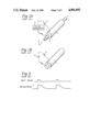
- FIG. 1A An ink jet recording head of this type has been proposed by U.S. Pat. No. 3,683,212 by Gould Inc.
- a cylindrical piezoelectric element 1 is polarized on its inner circumference and outer circumference, and a positive pulse voltage shown in FIG. 2 generated in response to an input signal by a pulse generator 2 is applied in the same direction as the polarization so that an impact stress is applied to the piezoelectric element 1 to cause a nozzle 4 to discharge an ink as an ink droplet 3 stored in the piezoelectric element.
- Arrows in FIG. 1B show the directions of polarization.
- the ink surface at the end of the nozzle 4 is retracted but the surface tension of the ink at the nozzle acts to increase a radius of curvature of the ink surface.
- the ink is supplied into the nozzle 4 through an ink supply path 5.
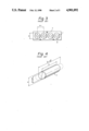
- a sectional shape of the piezoelectric element 1 of the prior art head is concentric and circular, when a plurality of heads are arranged in parallelly to form a multi-nozzle structure in order to increase the print speed or allow multi-color printing, a section of the entire head assembly includes a series of circles as shown in FIG. 3.
- a pitch P1 between the centers of the nozzles 4 must be larger than d (P1>d).
- the head assembly is of large size for the multi-nozzle ink jet recording head.
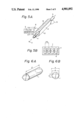
- a piezoelectric element of such shape if electrodes are arranged on the entire surfaces of the inner and outer circumferences of the cylinder and a voltage is applied thereacross, the cylindrical element is deformed in the inner circumference as shown in FIG. 4 by a reverse-piezoelectric effect.
- a solid line shows the original inner circumference of the piezoelectric element 1 and a broken line shows the inner circumference after the application of the voltage, and ⁇ l and ⁇ d represent variances of length and diameter.
- the length l changes to l+ ⁇ l while the diameter d changes to d- ⁇ d.
- a piezoelectric vibration mode is a combination of a longitudinal vibration and a lateral vibration and the cylindrical shape is maintained after the deformation. Accordingly, a sufficient electro-mechanical transducing efficiency is not attained.
- the length of the piezoelectric element on a cross-sectional plane along a predetermined direction is different from a length along the orthogonal direction.
- no electrode is arranged on an inner circumference of the hollow piezoelectric element and electrodes are arranged only on an outer circumference.
- the outer circumference of the piezoelectric element has a plurality of electrodes arranged thereon which are not identical but a portion thereof is eliminated or of opposite polarity.
- the length of the piezoelectric device along one direction on the sectional plane is shorter than the length along the other direction, the length of the multi-nozzle assembly having a number of nozzles so arranged is short and a compact recording head is attained.
- the manufacture of the device is easy and the deformation due to the application of voltage does not occur toward the center but is limited in a certain direction. Thus, the electro-mechanical transducing efficiency is improved.
- a plurality of electrodes are arranged and positive pulse voltages of opposite polarity are applied to positive electrodes and negative electrodes in accordance with polarization to apply a contact force in one direction and a tensional force in the orthogonal direction.
- FIG. 1A shows a perspective view of a nozzle and a piezoelectric element in a prior art ink jet recording head
- FIG. 1B shows a perspective view for the illustrating polarization directions of the piezoelectric element
- FIG. 2 shows waveforms of pulse voltages applied to electrodes of the piezoelectric element in the prior art head shown in FIG. 1A,
- FIG. 3 shows a front view of a multi-nozzle assembly by arranging a plurality of prior art heads
- FIG. 4 shows a perspective view for illustrating deformation of the inner circumference of the prior art piezoelectric element shown in FIG. 1A
- FIG. 5A shows a perspective view of a nozzle and a piezoelectric element of one embodiment of an ink jet recording head of the present invention
- FIG. 5B shows a front view of a multi-nozzle assembly by a plurality of heads shown in FIG. 5A
- FIGS. 6A and 6B show a perspective view and a front view for illustrating the deformation of an inner circumference of the piezoelectric element shown in FIG. 5A
- FIGS. 7A to 7F show perspective views of other embodiments of the piezoelectric element of the present invention.
- FIGS. 8 and 9 show perspective views of further embodiments of the piezoelectric element of the present invention.
- FIG. 10 shows waveforms of pulse voltages applied to the electrodes of the piezoelectric element shown in FIG. 9.
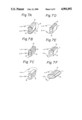
- FIG. 5A shows an external view of one embodiment of a piezoelectric element of the present invention
- FIG. 5B shows a multi-head assembly comprising a plurality of such piezoelectric elements
- Numeral 11 denotes a piezoelectric element
- numeral 12 denotes an upper or lower electrode
- numeral 13 denotes a wire for interconnecting the electrodes 12.
- Arrows in FIGS. 5A and 5B show the directions of polarization.
- the cylindrical piezoelectric element 11 has its both sides cut off to provide opposed, curved first surfaces and opposed second surfaces, so that the horizontal length on a cross-sectional plane is shorter than the vertical length, and the electrodes 12 are closely arranged to each other only on an upper surface and a lower surface.
- the cross-sectional configuration of the outer surface of element 12 includes an arc portion.
- a positive pulse voltage shown in FIG. 2 and generated by a pulse generator 2 is applied to the upper and lower electrodes 12 through the wires 6.
- the axial length l of the piezoelectric element 11 does not change but its vertical length is shortened and its horizontal length is expanded as shown in FIG. 6. Because the contraction occurs only in one direction, the circular inner circumference having a diameter d before the application of the voltage changes to an ellipse inner circumference having a major axis a and a minor axis b.
- a longitudinal piezoelectric constant d33 in the same direction as that of the applied electric field is several times as large as a lateral piezoelectric constant d31 in the orthogonal direction.
- d31 is approximately 2.9 ⁇ 10 m/V while d33 is approximately 6.4 ⁇ 10 m/V.
- the piezoelectric element 11 is deformed much more efficiently than the prior art piezoelectric element shown in FIG. 4.
- the electro-mechanical transducing efficiency is thus improved. Further, since the shape of the piezoelectric element 11 is not circular but the horizontal length is shorter than the vertical length, when a multi-nozzle assembly is to be constructed by a plurality of piezoelectric elements, a pitch P2 of the piezoelectric elements 11 is much smaller than the pitch P1 of the conventional piezoelectric elements shown in FIG. 3 and the overall width of the nozzle assembly 7 is short.
- FIGS. 7A to 7F show other embodiments of the piezoelectric element of the present invention.
- the piezoelectric element 11 in FIG. 7A is similar to that of the embodiment shown in FIG. 5A except that the electrodes 12 are removable plates.
- no electrode is arranged on the inner circumference of the piezoelectric element 11 and one side (left outer side) of the piezoelectric element 11 is grounded while the other side (right outer side) is used as a positive electrode.
- the polarization occurs laterally as shown by arrows.
- FIG. 7D no electrode is arranged on the inner circumference of the piezoelectric element 11, the outer lower surface of the piezoelectric element 11 is grounded and the outer upper surface is used as a positive electrode.
- the polarization occurs vertically or longitudinally as shown by arrows.
- the shape of the piezoelectric element 11 is oblong, and more specifically rectangular, the cross-sectional shape of the outer surface of element is square, and the element is polarized vertically.
- the cross-sectional shape of the piezoelectric element 11 is generally oblong, and more specifically is elliptical, and the element is polarized vertically.
- the polarization directions in both embodiments are same as that in the embodiment of FIG. 7D.
- the elongated piezoelectric element 11 shown in FIG. 7F may be used when a multi-head assembly is to be constructed by longitudinally (vertically) arranging a plurality of piezoelectric elements or laterally arranging them to reduce the thickness of the head assembly.
- the sectional shape of the piezoelectric element 11 is not limited to those shown in the above embodiments but may also encompass a laterally or longitudinally asymmetric sectional shape.
- the electrodes of the piezoelectric element 11 need not be identical on the inner circumference (that is, the hollow portion extending along the ink guiding path) or outer circumference of the piezoelectric element 11, but a portion thereof may be eliminated or may be of opposite polarity. As a result, the strain can be readily applied and the energy can be efficiently transmitted to the ink in the piezoelectric element 11.
- FIGS. 8 and 9 show other embodiments of the present invention.
- FIG. 8 (showing the case where one surface of the piezoelectric element has plural electrodes which are of opposite polarities), four electrodes 12 are mounted on the outer circumference of the cylindrical piezoelectric element 11 to divide it into four sectors.
- a pair of opposing upper and lower surfaces are used as positive electrodes and a pair of opposing left and right surfaces are grounded.
- the directions of polarization are grounded.
- the directions of polarization are shown by arrows.
- FIG. 9 shows the outer circumference of the cylindrical piezoelectric element 11 in the polarization direction.
- a pair of opposing upper and lower electrodes are connected to a positive terminal
- a pair of opposing left and right electrodes are connected to a negative terminal and the inner circumference of the piezoelectric element 11 is grounded.
- the polarization directions shown by arrows are directed from the center to the periphery on one hand and are directed from the periphery to the center on the other hand.
- a voltage waveform applied to the electrodes 12 when the number of electrodes is three is shown in FIG. 10. In the two-electrode structure, a positive voltage is applied to the piezoelectric element 11 in the polarization direction.
- the same voltage as that in the two-electrode structure is applied to the positive electrode and a positive voltage of the reverse waveform is applied to the negative electrode 12. Accordingly, as the electrode voltages are generated by the pulse generator 2 in accordance with the input signal, the inner circumference of the piezoelectric element 11 expands toward the positive electrode and contracts toward the negative electrode. Thus, the piezoelectric element 11 is more readily deformed and the electro-mechanical transducing efficiency is improved.
- the present invention offers the following significant advantages.
- the nozzle density is increased in a multi-nozzle assembly and a compact assembly is obtained.
Abstract
An ink jet recording head includes a piezoelectric element with an outer cross-sectional shape having opposed, curved first surfaces and opposed second surfaces, which may be formed by cutting off opposite sides of a circular cross-section piezoelectric element on diametrically opposed chords. An electric field applied to the piezoelectric element is stronger in one direction than another, thereby increasing the discharge efficiency of the ink jet head.
Description
This application is a continuation of application Ser. No. 941,362, filed Dec. 15, 1986, now abandoned.
1. Field of the Invention
The present invention relates to an ink jet recording head of an ink jet recorder for recording characters or images by discharging ink droplets toward a recording medium, and more particularly to such an ink jet recording head which uses a piezoelectric element as an electro-mechanical transducer for discharging the ink droplets.
2. Related Background Art
An ink jet recording head of this type has been proposed by U.S. Pat. No. 3,683,212 by Gould Inc. In this head, as shown in FIG. 1A, a cylindrical piezoelectric element 1 is polarized on its inner circumference and outer circumference, and a positive pulse voltage shown in FIG. 2 generated in response to an input signal by a pulse generator 2 is applied in the same direction as the polarization so that an impact stress is applied to the piezoelectric element 1 to cause a nozzle 4 to discharge an ink as an ink droplet 3 stored in the piezoelectric element. Arrows in FIG. 1B show the directions of polarization.
After the ink droplet has been discharged, the ink surface at the end of the nozzle 4 is retracted but the surface tension of the ink at the nozzle acts to increase a radius of curvature of the ink surface. Thus, the ink is supplied into the nozzle 4 through an ink supply path 5.
However, since a sectional shape of the piezoelectric element 1 of the prior art head is concentric and circular, when a plurality of heads are arranged in parallelly to form a multi-nozzle structure in order to increase the print speed or allow multi-color printing, a section of the entire head assembly includes a series of circles as shown in FIG. 3. Thus, when the diameter of the piezoelectric element 1 is represented by d, a pitch P1 between the centers of the nozzles 4 must be larger than d (P1>d). Thus, the head assembly is of large size for the multi-nozzle ink jet recording head.
On the other hand, in a piezoelectric element of such shape, if electrodes are arranged on the entire surfaces of the inner and outer circumferences of the cylinder and a voltage is applied thereacross, the cylindrical element is deformed in the inner circumference as shown in FIG. 4 by a reverse-piezoelectric effect. A solid line shows the original inner circumference of the piezoelectric element 1 and a broken line shows the inner circumference after the application of the voltage, and Δl and Δd represent variances of length and diameter. Thus, the length l changes to l+Δl while the diameter d changes to d-Δd. In the ink jet recording head of this type, since the electrodes of the piezoelectric element 1 are arranged over the entire surfaces of the inner circumference and the outer circumference of the cylinder, the manufacture of such a device is not easy. A piezoelectric vibration mode is a combination of a longitudinal vibration and a lateral vibration and the cylindrical shape is maintained after the deformation. Accordingly, a sufficient electro-mechanical transducing efficiency is not attained.
It is an object of the present invention to provide a high performance ink jet recording head which resolves the above problems.
In accordance with the present invention, in an ink jet recording head for discharging ink droplets to a recording medium by a hollow piezoelectric element to record characters or image, the length of the piezoelectric element on a cross-sectional plane along a predetermined direction is different from a length along the orthogonal direction.
In accordance with the ink jet recording head of the present invention, no electrode is arranged on an inner circumference of the hollow piezoelectric element and electrodes are arranged only on an outer circumference.
In accordance with the ink jet recording head of the present invention, in order to discharge ink droplets to a recording medium by the hollow piezoelectric element to record characters or images, the outer circumference of the piezoelectric element has a plurality of electrodes arranged thereon which are not identical but a portion thereof is eliminated or of opposite polarity.
In the present invention, since the length of the piezoelectric device along one direction on the sectional plane is shorter than the length along the other direction, the length of the multi-nozzle assembly having a number of nozzles so arranged is short and a compact recording head is attained.
Since one surface of the piezoelectric element has no electrode or has electrodes of opposite polarity the manufacture of the device is easy and the deformation due to the application of voltage does not occur toward the center but is limited in a certain direction. Thus, the electro-mechanical transducing efficiency is improved.
A plurality of electrodes are arranged and positive pulse voltages of opposite polarity are applied to positive electrodes and negative electrodes in accordance with polarization to apply a contact force in one direction and a tensional force in the orthogonal direction. Thus, deformation is readily attained, the electro-mechanical transducing efficiency is improved and the response is also improved.
It is an object of the present invention to provide an ink jet recording head having a hollow piezoelectric element, the deformation of the hollow piezoelectric element which is caused by the application of voltage to the piezoelectric element causing ink which may be filled in the hollow piezoelectric element to be discharged toward a recording medium, and the cross-sectional shape of the outer surface of hollow piezoelectric element in a plane perpendicular to the direction in which the ink is discharged being noncircular.
It is further object of the present invention to provide an ink jet recording head having a hollow piezoelectric element, the deformation of the hollow piezoelectric element which is caused by the application of voltage to the piezoelectric element causing ink which may be filled in the hollow piezoelectric element to be discharged toward a recording medium, and the piezoelectric element having an electrode for voltage application being arranged only one of outer surface side and inner circumference of said hollow piezoelectric element.
FIG. 1A shows a perspective view of a nozzle and a piezoelectric element in a prior art ink jet recording head,
FIG. 1B shows a perspective view for the illustrating polarization directions of the piezoelectric element,
FIG. 2 shows waveforms of pulse voltages applied to electrodes of the piezoelectric element in the prior art head shown in FIG. 1A,
FIG. 3 shows a front view of a multi-nozzle assembly by arranging a plurality of prior art heads,
FIG. 4 shows a perspective view for illustrating deformation of the inner circumference of the prior art piezoelectric element shown in FIG. 1A,
FIG. 5A shows a perspective view of a nozzle and a piezoelectric element of one embodiment of an ink jet recording head of the present invention,
FIG. 5B shows a front view of a multi-nozzle assembly by a plurality of heads shown in FIG. 5A,
FIGS. 6A and 6B show a perspective view and a front view for illustrating the deformation of an inner circumference of the piezoelectric element shown in FIG. 5A,
FIGS. 7A to 7F show perspective views of other embodiments of the piezoelectric element of the present invention,
FIGS. 8 and 9 show perspective views of further embodiments of the piezoelectric element of the present invention, and
FIG. 10 shows waveforms of pulse voltages applied to the electrodes of the piezoelectric element shown in FIG. 9.
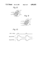
FIG. 5A shows an external view of one embodiment of a piezoelectric element of the present invention, and FIG. 5B shows a multi-head assembly comprising a plurality of such piezoelectric elements. Numeral 11 denotes a piezoelectric element, numeral 12 denotes an upper or lower electrode and numeral 13 denotes a wire for interconnecting the electrodes 12. Arrows in FIGS. 5A and 5B show the directions of polarization. As shown in FIG. 5A, the cylindrical piezoelectric element 11 has its both sides cut off to provide opposed, curved first surfaces and opposed second surfaces, so that the horizontal length on a cross-sectional plane is shorter than the vertical length, and the electrodes 12 are closely arranged to each other only on an upper surface and a lower surface. Also, the cross-sectional configuration of the outer surface of element 12 includes an arc portion.
In a print operation, a positive pulse voltage shown in FIG. 2 and generated by a pulse generator 2 is applied to the upper and lower electrodes 12 through the wires 6.
When the voltage is applied to the electrodes 12, the axial length l of the piezoelectric element 11 does not change but its vertical length is shortened and its horizontal length is expanded as shown in FIG. 6. Because the contraction occurs only in one direction, the circular inner circumference having a diameter d before the application of the voltage changes to an ellipse inner circumference having a major axis a and a minor axis b.
For a normal material used in the piezoelectric element, a longitudinal piezoelectric constant d33 in the same direction as that of the applied electric field is several times as large as a lateral piezoelectric constant d31 in the orthogonal direction. In an experiment, d31 is approximately 2.9×10 m/V while d33 is approximately 6.4×10 m/V.
Thus, in accordance with the present embodiment, the piezoelectric element 11 is deformed much more efficiently than the prior art piezoelectric element shown in FIG. 4.
In accordance with the present embodiment, the electro-mechanical transducing efficiency is thus improved. Further, since the shape of the piezoelectric element 11 is not circular but the horizontal length is shorter than the vertical length, when a multi-nozzle assembly is to be constructed by a plurality of piezoelectric elements, a pitch P2 of the piezoelectric elements 11 is much smaller than the pitch P1 of the conventional piezoelectric elements shown in FIG. 3 and the overall width of the nozzle assembly 7 is short.
FIGS. 7A to 7F show other embodiments of the piezoelectric element of the present invention.
The piezoelectric element 11 in FIG. 7A is similar to that of the embodiment shown in FIG. 5A except that the electrodes 12 are removable plates.
In FIG. 7B, the inner circumference of the piezoelectric element 11 is grounded and the outer surface is positive.
In FIG. 7C, no electrode is arranged on the inner circumference of the piezoelectric element 11 and one side (left outer side) of the piezoelectric element 11 is grounded while the other side (right outer side) is used as a positive electrode. The polarization occurs laterally as shown by arrows.
In FIG. 7D, no electrode is arranged on the inner circumference of the piezoelectric element 11, the outer lower surface of the piezoelectric element 11 is grounded and the outer upper surface is used as a positive electrode. The polarization occurs vertically or longitudinally as shown by arrows.
In FIG. 7E, the shape of the piezoelectric element 11 is oblong, and more specifically rectangular, the cross-sectional shape of the outer surface of element is square, and the element is polarized vertically. In FIG. 7F, the cross-sectional shape of the piezoelectric element 11 is generally oblong, and more specifically is elliptical, and the element is polarized vertically. The polarization directions in both embodiments are same as that in the embodiment of FIG. 7D. The elongated piezoelectric element 11 shown in FIG. 7F may be used when a multi-head assembly is to be constructed by longitudinally (vertically) arranging a plurality of piezoelectric elements or laterally arranging them to reduce the thickness of the head assembly.
The sectional shape of the piezoelectric element 11 is not limited to those shown in the above embodiments but may also encompass a laterally or longitudinally asymmetric sectional shape. The electrodes of the piezoelectric element 11 need not be identical on the inner circumference (that is, the hollow portion extending along the ink guiding path) or outer circumference of the piezoelectric element 11, but a portion thereof may be eliminated or may be of opposite polarity. As a result, the strain can be readily applied and the energy can be efficiently transmitted to the ink in the piezoelectric element 11.
FIGS. 8 and 9 show other embodiments of the present invention. In FIG. 8, (showing the case where one surface of the piezoelectric element has plural electrodes which are of opposite polarities), four electrodes 12 are mounted on the outer circumference of the cylindrical piezoelectric element 11 to divide it into four sectors. A pair of opposing upper and lower surfaces are used as positive electrodes and a pair of opposing left and right surfaces are grounded. The directions of polarization are grounded. The directions of polarization are shown by arrows.
In FIG. 9, (showing the case where some electrodes are eliminated) the outer circumference of the cylindrical piezoelectric element 11 is divided into four sectors by four electrodes 12. A pair of opposing upper and lower electrodes are connected to a positive terminal, a pair of opposing left and right electrodes are connected to a negative terminal and the inner circumference of the piezoelectric element 11 is grounded. The polarization directions shown by arrows are directed from the center to the periphery on one hand and are directed from the periphery to the center on the other hand. A voltage waveform applied to the electrodes 12 when the number of electrodes is three is shown in FIG. 10. In the two-electrode structure, a positive voltage is applied to the piezoelectric element 11 in the polarization direction. In the three-electrode structure shown in the embodiment of FIG. 9, the same voltage as that in the two-electrode structure is applied to the positive electrode and a positive voltage of the reverse waveform is applied to the negative electrode 12. Accordingly, as the electrode voltages are generated by the pulse generator 2 in accordance with the input signal, the inner circumference of the piezoelectric element 11 expands toward the positive electrode and contracts toward the negative electrode. Thus, the piezoelectric element 11 is more readily deformed and the electro-mechanical transducing efficiency is improved.
The present invention offers the following significant advantages.
(1) Since the cross-sectional plane of the piezoelectric element is not circular but one of the vertical and horizontal lengths in the cross-sectional plane of the element is shorter than the other, the nozzle density is increased in a multi-nozzle assembly and a compact assembly is obtained.
(2) Because the electrodes are arranged only on the outer side of the piezoelectric element, the manufacturing process is simplified and the manufacturing cost is reduced.
(3) Because the electrodes on the inner or outer circumference of the piezoelectric element are not identical but are arranged only on an axial area to disperse the stress, the electro-mechanical transducing efficiency is improved.
(4) Because a portion of the electrodes on at least one of the outer circumference and inner circumference of the piezoelectric element is eliminated or is of opposite polarity, a mechanical stress can be readily applied and the energy can be efficiently transmitted to the ink in the piezoelectric element. Accordingly, the response is high, the discharge pressure can be readily changed, the pressure range is wide and the durability is high.
Claims (16)
1. An ink jet recording head including a piezoelectric element having an outer cross-sectional shape in a plane perpendicular to the direction in which ink is discharged therefrom, said shape comprising opposed, curved first surfaces and opposed second surfaces, and having an inner surface defining a hollow portion providing a path for guiding the ink to be discharged from the head, wherein:
one of said first surfaces has an electrode disposed thereon, and
said piezoelectric element is deformable by applying a voltage to said electrode to create in said plane an electric field stronger in one direction than in a direction different from said one direction to more efficiently discharge ink.
2. An ink jet recording head according to claim 1, wherein another electrode is disposed on said inner surface and said piezoelectric element is deformable by applying a voltage between said electrodes.
3. An ink jet recording head according to claim 1, wherein another electrode is disposed on one of said second surfaces and piezoelectric element is deformable by applying a voltage between said electrodes.
4. An ink jet recording head according to any one of claims 1 and 3, comprising plural said piezoelectric elements disposed side by side with said second surfaces located adjacent to each other.
5. An ink jet recording head according to claim 1, wherein said shape of said piezoelectric element has a length in one direction different from the length in an orthogonal direction.
6. An ink jet recording head according to claim 5, wherein said electrode is film shaped.
7. An ink jet recording head according to claim 5, wherein said electrode is a plate.
8. An ink jet recording head according to claim 5, wherein said electrode is detachable from said piezoelectric element.
9. An ink jet recording head including a piezoelectric element having an outer cross-sectional shape in a plane perpendicular to the direction in which ink is discharged therefrom, said shape comprising opposed, curved first surfaces and opposed second surfaces, and having an inner surface defining a hollow portion providing a path for guiding the ink to be discharged from the head, wherein:
one of said second surfaces has a first electrode disposed thereon, and
said piezoelectric element is deformable by applying a voltage to said electrode to create in said plane an electric field stronger in one direction than in a direction different from said one direction to more efficiently discharge ink.
10. An ink jet recording head according to claim 9, wherein another electrode is disposed on said inner surface said piezoelectric element is deformable by applying a voltage between said electrodes.
11. An ink jet recording head according to claim 9, wherein another electrode is disposed on the other said second surface.
12. An ink jet recording head according to claim 9, comprising plural said piezoelectric elements disposed side by side with said second surfaces located adjacent to each other.
13. An ink jet recording head according to claim 9, wherein said outer shape of said piezoelectric element has a length in one direction different from the length in an orthogonal direction.
14. An ink jet recording head according to claim 13, wherein said electrode is film shaped.
15. An ink jet recording head according to claim 13, wherein said electrode is a plate.
16. An ink jet recording head according to claim 13, wherein said electrode is detachable from said piezoelectric element.
Priority Applications (1)
| Application Number | Priority Date | Filing Date | Title |
|---|---|---|---|
| US07/435,244 US5172141A (en) | 1985-12-17 | 1989-11-13 | Ink jet recording head using a piezoelectric element having an asymmetrical electric field applied thereto |
Applications Claiming Priority (2)
| Application Number | Priority Date | Filing Date | Title |
|---|---|---|---|
| JP60-281863 | 1985-12-17 | ||
| JP60281863A JPS62140851A (en) | 1985-12-17 | 1985-12-17 | Ink jet recording head |
Related Parent Applications (1)
| Application Number | Title | Priority Date | Filing Date |
|---|---|---|---|
| US94136286A Continuation | 1985-12-17 | 1986-12-15 |
Related Child Applications (1)
| Application Number | Title | Priority Date | Filing Date |
|---|---|---|---|
| US07/435,244 Continuation US5172141A (en) | 1985-12-17 | 1989-11-13 | Ink jet recording head using a piezoelectric element having an asymmetrical electric field applied thereto |
Publications (1)
| Publication Number | Publication Date |
|---|---|
| US4901092A true US4901092A (en) | 1990-02-13 |
Family
ID=17645042
Family Applications (1)
| Application Number | Title | Priority Date | Filing Date |
|---|---|---|---|
| US07/252,002 Expired - Lifetime US4901092A (en) | 1985-12-17 | 1988-09-30 | Ink jet recording head using a piezoelectric element having an asymmetrical electric field applied thereto |
Country Status (2)
| Country | Link |
|---|---|
| US (1) | US4901092A (en) |
| JP (1) | JPS62140851A (en) |
Cited By (8)
| Publication number | Priority date | Publication date | Assignee | Title |
|---|---|---|---|---|
| WO1992008617A1 (en) * | 1990-11-20 | 1992-05-29 | Spectra, Inc. | Piezoelectric transducers for ink jet systems |
| US5172141A (en) * | 1985-12-17 | 1992-12-15 | Canon Kabushiki Kaisha | Ink jet recording head using a piezoelectric element having an asymmetrical electric field applied thereto |
| US5745129A (en) * | 1992-06-01 | 1998-04-28 | Canon Kabushiki Kaisha | Ink jet head, ink jet apparatus and driving method therefor |
| US5867193A (en) * | 1993-07-30 | 1999-02-02 | Nec Corporation | Ink-jet printing head having pieozoelectric blocks with electrodes on ends perpendicular to axial direction of bores |
| US6070973A (en) * | 1997-05-15 | 2000-06-06 | Massachusetts Institute Of Technology | Non-resonant and decoupled droplet generator |
| US20030142153A1 (en) * | 2001-04-02 | 2003-07-31 | Yoshinori Nakajima | Printing head, image printing apparatus using the same, and control method therefor |
| US20040217186A1 (en) * | 2003-04-10 | 2004-11-04 | Sachs Emanuel M | Positive pressure drop-on-demand printing |
| CN111516392A (en) * | 2019-02-01 | 2020-08-11 | 东芝泰格有限公司 | Ink jet recording apparatus |
Families Citing this family (3)
| Publication number | Priority date | Publication date | Assignee | Title |
|---|---|---|---|---|
| EP1013422B1 (en) * | 1998-12-14 | 2006-08-23 | Eastman Kodak Company | Drop generator for long array ink jet printer |
| EP1116590B1 (en) * | 2000-01-11 | 2003-09-17 | Samsung Electronics Co., Ltd. | Ink-jet head device with multi-stacked PZT actuator |
| JP4622607B2 (en) * | 2005-03-22 | 2011-02-02 | 富士ゼロックス株式会社 | Droplet discharge head and droplet discharge apparatus |
Citations (13)
| Publication number | Priority date | Publication date | Assignee | Title |
|---|---|---|---|---|
| US3683212A (en) * | 1970-09-09 | 1972-08-08 | Clevite Corp | Pulsed droplet ejecting system |
| US3924974A (en) * | 1973-05-21 | 1975-12-09 | Rca Corp | Fluid ejection or control device |
| US4245227A (en) * | 1978-11-08 | 1981-01-13 | International Business Machines Corporation | Ink jet head having an outer wall of ink cavity of piezoelectric material |
| US4288799A (en) * | 1979-05-14 | 1981-09-08 | Canon Kabushiki Kaisha | Liquid jet recording head with permanent jig alignment |
| US4306245A (en) * | 1978-09-21 | 1981-12-15 | Canon Kabushiki Kaisha | Liquid jet device with cleaning protective means |
| US4342041A (en) * | 1979-08-15 | 1982-07-27 | Canon Kabushiki Kaisha | Ink jet type recording apparatus |
| US4368477A (en) * | 1980-05-23 | 1983-01-11 | Siemens Aktiengesellschaft | Arrangement for a printing head in ink mosaic printing devices |
| US4390886A (en) * | 1981-09-25 | 1983-06-28 | Xerox Corporation | Ink jet printing machine |
| US4395719A (en) * | 1981-01-05 | 1983-07-26 | Exxon Research And Engineering Co. | Ink jet apparatus with a flexible piezoelectric member and method of operating same |
| US4429320A (en) * | 1979-09-21 | 1984-01-31 | Canon Kabushiki Kaisha | Ink jet recording apparatus |
| US4499479A (en) * | 1982-08-30 | 1985-02-12 | International Business Machines Corporation | Gray scale printing with ink jet drop-on demand printing head |
| US4560997A (en) * | 1982-07-07 | 1985-12-24 | Canon Kabushiki Kaisha | Method and apparatus for forming a pattern |
| US4578686A (en) * | 1984-02-02 | 1986-03-25 | Siemens Aktiengesellschaft | Ink printhead |
-
1985
- 1985-12-17 JP JP60281863A patent/JPS62140851A/en active Pending
-
1988
- 1988-09-30 US US07/252,002 patent/US4901092A/en not_active Expired - Lifetime
Patent Citations (13)
| Publication number | Priority date | Publication date | Assignee | Title |
|---|---|---|---|---|
| US3683212A (en) * | 1970-09-09 | 1972-08-08 | Clevite Corp | Pulsed droplet ejecting system |
| US3924974A (en) * | 1973-05-21 | 1975-12-09 | Rca Corp | Fluid ejection or control device |
| US4306245A (en) * | 1978-09-21 | 1981-12-15 | Canon Kabushiki Kaisha | Liquid jet device with cleaning protective means |
| US4245227A (en) * | 1978-11-08 | 1981-01-13 | International Business Machines Corporation | Ink jet head having an outer wall of ink cavity of piezoelectric material |
| US4288799A (en) * | 1979-05-14 | 1981-09-08 | Canon Kabushiki Kaisha | Liquid jet recording head with permanent jig alignment |
| US4342041A (en) * | 1979-08-15 | 1982-07-27 | Canon Kabushiki Kaisha | Ink jet type recording apparatus |
| US4429320A (en) * | 1979-09-21 | 1984-01-31 | Canon Kabushiki Kaisha | Ink jet recording apparatus |
| US4368477A (en) * | 1980-05-23 | 1983-01-11 | Siemens Aktiengesellschaft | Arrangement for a printing head in ink mosaic printing devices |
| US4395719A (en) * | 1981-01-05 | 1983-07-26 | Exxon Research And Engineering Co. | Ink jet apparatus with a flexible piezoelectric member and method of operating same |
| US4390886A (en) * | 1981-09-25 | 1983-06-28 | Xerox Corporation | Ink jet printing machine |
| US4560997A (en) * | 1982-07-07 | 1985-12-24 | Canon Kabushiki Kaisha | Method and apparatus for forming a pattern |
| US4499479A (en) * | 1982-08-30 | 1985-02-12 | International Business Machines Corporation | Gray scale printing with ink jet drop-on demand printing head |
| US4578686A (en) * | 1984-02-02 | 1986-03-25 | Siemens Aktiengesellschaft | Ink printhead |
Cited By (12)
| Publication number | Priority date | Publication date | Assignee | Title |
|---|---|---|---|---|
| US5172141A (en) * | 1985-12-17 | 1992-12-15 | Canon Kabushiki Kaisha | Ink jet recording head using a piezoelectric element having an asymmetrical electric field applied thereto |
| WO1992008617A1 (en) * | 1990-11-20 | 1992-05-29 | Spectra, Inc. | Piezoelectric transducers for ink jet systems |
| US5202703A (en) * | 1990-11-20 | 1993-04-13 | Spectra, Inc. | Piezoelectric transducers for ink jet systems |
| US5745129A (en) * | 1992-06-01 | 1998-04-28 | Canon Kabushiki Kaisha | Ink jet head, ink jet apparatus and driving method therefor |
| US5867193A (en) * | 1993-07-30 | 1999-02-02 | Nec Corporation | Ink-jet printing head having pieozoelectric blocks with electrodes on ends perpendicular to axial direction of bores |
| US6070973A (en) * | 1997-05-15 | 2000-06-06 | Massachusetts Institute Of Technology | Non-resonant and decoupled droplet generator |
| US20030142153A1 (en) * | 2001-04-02 | 2003-07-31 | Yoshinori Nakajima | Printing head, image printing apparatus using the same, and control method therefor |
| US6997533B2 (en) | 2001-04-02 | 2006-02-14 | Canon Kabushiki Kaisha | Printing head, image printing apparatus, and control method employing block driving of printing elements |
| US7448709B2 (en) | 2001-04-02 | 2008-11-11 | Canon Kabushiki Kaisha | Printing head, image printing apparatus using the same, and control method therefor |
| US20040217186A1 (en) * | 2003-04-10 | 2004-11-04 | Sachs Emanuel M | Positive pressure drop-on-demand printing |
| US7077334B2 (en) | 2003-04-10 | 2006-07-18 | Massachusetts Institute Of Technology | Positive pressure drop-on-demand printing |
| CN111516392A (en) * | 2019-02-01 | 2020-08-11 | 东芝泰格有限公司 | Ink jet recording apparatus |
Also Published As
| Publication number | Publication date |
|---|---|
| JPS62140851A (en) | 1987-06-24 |
Similar Documents
| Publication | Publication Date | Title |
|---|---|---|
| US5235352A (en) | High density ink jet printhead | |
| US5028936A (en) | Pulsed droplet deposition apparatus using unpoled crystalline shear mode actuator | |
| US4962391A (en) | Ink jet printer head | |
| US4901092A (en) | Ink jet recording head using a piezoelectric element having an asymmetrical electric field applied thereto | |
| US20020018095A1 (en) | Ink jet head | |
| EP0095911A2 (en) | Pressure pulse droplet ejector and array | |
| US6921149B2 (en) | Liquid drop discharging head and liquid drop discharging device | |
| US5172141A (en) | Ink jet recording head using a piezoelectric element having an asymmetrical electric field applied thereto | |
| KR960003359B1 (en) | Piezoelectric transducer for ink jet systems | |
| CA1098161A (en) | Ink jet printing head | |
| US5471231A (en) | Ink jet head | |
| US4752789A (en) | Multi-layer transducer array for an ink jet apparatus | |
| US5373314A (en) | Ink jet print head | |
| US5854645A (en) | Inkjet array | |
| JP2695418B2 (en) | On-demand type inkjet head | |
| US6243114B1 (en) | Ink jet head providing improved printing resolution and printing speed | |
| US5543009A (en) | Method of manufacturing a sidewall actuator array for an ink jet printhead | |
| JPH04148934A (en) | Ink jet head | |
| JP3129090B2 (en) | Inkjet head | |
| JP2729008B2 (en) | Ink jet recording head device | |
| JP3257054B2 (en) | Droplet discharge device and driving method thereof | |
| JPH01235648A (en) | Ink jet head | |
| JP3221405B2 (en) | Inkjet recording head | |
| JPH06182994A (en) | Ink jet recorder | |
| JP3087343B2 (en) | Inkjet head |
Legal Events
| Date | Code | Title | Description |
|---|---|---|---|
| STCF | Information on status: patent grant |
Free format text: PATENTED CASE |
|
| CC | Certificate of correction | ||
| FEPP | Fee payment procedure |
Free format text: PAYOR NUMBER ASSIGNED (ORIGINAL EVENT CODE: ASPN); ENTITY STATUS OF PATENT OWNER: LARGE ENTITY |
|
| FPAY | Fee payment |
Year of fee payment: 4 |
|
| FPAY | Fee payment |
Year of fee payment: 8 |
|
| FEPP | Fee payment procedure |
Free format text: PAYER NUMBER DE-ASSIGNED (ORIGINAL EVENT CODE: RMPN); ENTITY STATUS OF PATENT OWNER: LARGE ENTITY |
|
| FPAY | Fee payment |
Year of fee payment: 12 |