US4900962A - Magnetic translator bearings - Google Patents
Magnetic translator bearings Download PDFInfo
- Publication number
- US4900962A US4900962A US07/298,644 US29864489A US4900962A US 4900962 A US4900962 A US 4900962A US 29864489 A US29864489 A US 29864489A US 4900962 A US4900962 A US 4900962A
- Authority
- US
- United States
- Prior art keywords
- magnetic bearing
- carriage
- pole
- pole piece
- shaft
- Prior art date
- Legal status (The legal status is an assumption and is not a legal conclusion. Google has not performed a legal analysis and makes no representation as to the accuracy of the status listed.)
- Expired - Lifetime
Links
Images


Classifications
-
- F—MECHANICAL ENGINEERING; LIGHTING; HEATING; WEAPONS; BLASTING
- F16—ENGINEERING ELEMENTS AND UNITS; GENERAL MEASURES FOR PRODUCING AND MAINTAINING EFFECTIVE FUNCTIONING OF MACHINES OR INSTALLATIONS; THERMAL INSULATION IN GENERAL
- F16C—SHAFTS; FLEXIBLE SHAFTS; ELEMENTS OR CRANKSHAFT MECHANISMS; ROTARY BODIES OTHER THAN GEARING ELEMENTS; BEARINGS
- F16C29/00—Bearings for parts moving only linearly
-
- F—MECHANICAL ENGINEERING; LIGHTING; HEATING; WEAPONS; BLASTING
- F16—ENGINEERING ELEMENTS AND UNITS; GENERAL MEASURES FOR PRODUCING AND MAINTAINING EFFECTIVE FUNCTIONING OF MACHINES OR INSTALLATIONS; THERMAL INSULATION IN GENERAL
- F16C—SHAFTS; FLEXIBLE SHAFTS; ELEMENTS OR CRANKSHAFT MECHANISMS; ROTARY BODIES OTHER THAN GEARING ELEMENTS; BEARINGS
- F16C32/00—Bearings not otherwise provided for
- F16C32/04—Bearings not otherwise provided for using magnetic or electric supporting means
- F16C32/0406—Magnetic bearings
- F16C32/044—Active magnetic bearings
- F16C32/0472—Active magnetic bearings for linear movement
Definitions
- This invention relates to an improved magnetic bearing system for translational motion, and more articularly to such a bearing system which directly replaces air bearings in present optical disk data-storage devices.
- Non-contact bearings are essential in the support and positioning of optical read/write heads of high-density, high-data rate, high-performance optical disks.
- Air bearings are used for this purpose in a number of applications, but they suffer from a number of shortcomings.
- One problem is that they need a complete pneumatic system--pumps, valves, seals, conduits--for their operation.
- Another problem is that they require air, an element not readily available in space applications where high-performance optical disk data-storage systems are the technology of choice. In any environment the air supply system adds significant cost, size and weight to the bearing package and introduces the inherent reliability problems associated with pneumatic systems components such as pumps and seals.
- Air bearings themselves are difficult and expensive to manufacture because of the small tolerance required, in the order of one ten thousandth of an inch. Air bearings are highly susceptible to contaminants: a particle of dust can interfere with air gaps as small as four ten-thousandths of an inch and clog pores of the graphite or other diffusive coating.
- This invention results from the realization that a truly effective magnetic bearing for replacing existing air bearings in optical storage devices can be achieved by employing the same shaft and carriage assembly using magnetic bearings and channels to precisely, gently and frictionlessly guide the carriage movement on the shafts.
- This invention features a magnetic bearing system for enabling translational motion.
- carriage means and shaft means for movably supporting the carriage means.
- the first channel is generally "U" shaped, with two side walls and a back wall.
- the magnetic bearing means includes a magnetic bearing having a pair of spaced magnetic pole pieces, each pole piece having a pair of electromagnetic coils mounted on poles on opposite ends of the pole piece proximate the side walls, and a third electromagnetic coil mounted on a pole of the pole piece proximate the back wall.
- Means responsive to the means for sensing generate correction signals to drive the coil, to compensate for any misalignment sensed between the carriage and shaft means.
- the pair of electromagnetic coils mounted on the poles at opposite ends of the pole piece are electrically connected in series.
- the first magnetic bearing means may include permanent magnet means associated with the pole pieces for establishing a steady biasing magnetic field in the pole pieces.
- the system may include a second magnetic bearing fixed to one of the carriage means and shaft means and slidably received in a second channel in the other of the carriage and shaft means.
- the second channel also has two side walls and a back wall. The two channels face in the opposite direction.
- the second magnetic bearing means may include a pair of spaced pole pieces, each pole piece having a pair of electromagnetic coils mounted on poles on opposite ends of the pole piece proximate the side wall, and a third electromagnetic coil mounted on the pole of the pole piece proximate the back wall.
- the pairs of electromagnetic coils mounted on the pole pieces of the second magnetic bearing means at opposite ends of the pole pieces may be electrically connected in series.
- the second magnetic bearing means may include permanent magnet means associated with the pole pieces for establishing a steady biasing magnetic field in the pole pieces.
- the third electromagnetic coil mounted on the pole of each pole piece in the first magnetic bearing means may be electrically connected in series with the corresponding third electromagnetic coil means mounted on a pole of each pole piece in the second magnetic bearing means.
- the channel means may be in the shaft means and the bearing means may be in the carriage means, or conversely.
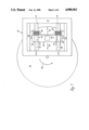
- FIG. 1 is a diagrammatic top plan view of an optical read/write head for an optical disk data-storage device using the magnetic bearings according to this invention
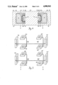
- FIG. 2 is a sectional view taken along lines 2--2 of FIG. 1, extended into a three-dimensional diagram showing one of the magnetic bearings of FIG. 1 according to this invention;
- FIG. 3 is a view similar to that of FIG. 2 illustrating a steady state magnetic field provided by a permanent magnet in the magnetic bearing;
- FIG. 4 is a diagrammatic cross-sectional view taken along lines 4--4 FIG. 1;
- FIG. 5 is an exploded three-dimensional view showing the relative positioning and interconnection of the coils illustrated in 1, 2 and 4;
- FIG. 6 schematic of the coil winding interconnections and current flows of one of the groups of coils of FIG. 5;
- FIG. 7 enlarged three-dimensional view of the carriage of FIG. 1 illustrating the location of the position sensors
- FIG. 8 schematic block diagram of the correction circuit which senses the position of the carriage and shaft relative to one another and provides compensating signals to the coils to correct any misalignment
- FIG. 9 an axonometric view of a bearing similar to that shown in FIG. 2, arranged for use singly.
- Read/write head assembly 10 for an optical storage disk 12.
- Read/write head assembly 10 includes an iron frame 14 suspended across which are two iron shafts 16 and 18.
- a carriage 20 slides to and fro on shafts 18 and 20 in the direction indicated by arrows 22 and 24 radially back and forth across optical disk 12, which is rotating as indicated by arrow 26.
- Carriage 20 is driven by a pair of linear motors in a conventional manner.
- One linear motor is comprised of permanent magnet 30 which interacts with the current in coil 32 fixed to carriage 20.
- the second linear motor is comprised of permanent magnet 34 which interacts with the current in coil 36, also fixed to carriage 20.
- the magnetic fields between the permanent magnets 30 and 34 and the current in their respective coils 32 and 36 generate Lorentz forces which move the carriage back and forth on shafts 16 and 18 in a conventional manner.
- Magnetic bearing 40 is fixed to carriage 20 in passageway 44, where it is received in channel 46 in shaft 16 which forms a first assembly A.
- Magnetic bearing 42 is fixed to carriage 20 in passageway 50 and is received in channel 52 in shaft 18 to constitute assembly B.
- the channels are shown disposed in the shafts and the magnetic bearings are shown attached to the carriage, this is not a necessary limitation of the invention.
- the bearings can be on the shafts and the channels could be formed in the carriage, or one bearing could be formed on the carriage and one on a shaft with the channels in complementary positions.
- Bearing 40 includes two pole pieces 60 and 62.
- Channel 46 includes two side walls 64 and 66, and a back wall 68 and is therefore generally "U"-shaped.
- Pole piece 60 includes a pair of poles 70 and 72 on opposite ends of pole piece 60 facing side walls 64 and 66.
- a third pole piece 74 faces back wall 68.
- the gap 76 between the poles and channel 46 is typically on the order of ten to twenty thousandths of an inch.
- a pair of coils 80, 82 are mounted on poles 70 and 72, and a third coil 84 is mounted on pole 74.
- the second pole piece 62 includes similar pole pieces 86, 88 and 90 with similar coils 92, 94, and 96.
- a permanent magnet 98 may be provided to establish a steady magnetic field through the pole pieces and channel, as shown in FIG. 3, where the steady field provided by magnet 98 is shown in solid lines 100 and the field provided by the coils 80 and 82 is shown in dashed lines 102. In FIG. 3 the coils have been eliminated for clarity. It can be seen here that while tee two fields add in pole 72 and side wall 66, they subtract in pole 70 and side wall 64 to provide the adjusting magnetic forces, as is explained hereafter. Although in this embodiment a permanent magnet is shown as part of a magnetic bearing, this is not a necessary limitation of the invention. A permanent magnet is used when a linear, low-power force adjustment is desirable. In applications where that is not required, the magnet is not used and corrections are applied only through the electromagnetic coil.
- FIG. 4 illustrates that magnetic bearings 40 and 42 fixed to carriage 20 are slidably received in channels 46 and 52 of shafts 16 and 18, which are themselves slidably receivable in passageways 44 and 50 of carriage 20.
- Magnetic force is applied by the permanent magnet and by the coils so that the coils 84, 84', shown, and 96 and 96', not shown, can create offsetting magnetic forces that balance the carriage support from left to right in FIG. 4 in the same way that coils 80, 82, 80', 82', shown, and 92, 94, 92', 94', not shown, perform in the vertical direction as shown in FIG. 4.
- channels 46 and 52 face in opposite directions.
- FIG. 5 The connection of the coils is shown in FIG. 5.
- coils 80 and 82 of pole piece 60 are connected in series, and coils 92 and 94 of pole piece 62 are connected in series.
- coils 80' and 82' of pole piece 60' are connected in series, and coils 92' and 94' of pole piece 62' are connected in series.
- Coil 84 of pole piece 60 is also connected in series with coil 84' of pole piece 60', and coil 96 of pole piece 62 is connected in series with coil 96' of pole piece 62' While this is the preferred electrical interconnection, it is not a necessary limitation, as each of the coils could be energized individually to provide the proper alignment correction between carriage 20 and shafts 16 and 18.
- FIG. 6 The energization of the coils as connected in FIG. 5 is illustrated schematically in FIG. 6.
- Current flowing into coil 82 at terminal 110 flows in the same direction in coil 82 and in coil 80, creating the magnetic fields 102 which combine with the field 100 of the permanent magnet, FIG. 3, to provide the necessary righting forces and moments to keep the carriage and shafts properly aligned.
- coils 84 and 84', FIG. 6, are interconnected so that a current introduced at terminal 112 flows in the opposite direction in coils 84 and 84', to provide the necessary magnetic balancing forces.
- These sensors are capacitive sensors such as concentric conductive rings or similar elements.
- the signals from sensors A1-A4 and B1-B4 are delivered to sensor interface circuits 120, FIG. 8, where they are filtered, shaped and amplified, and delivered to sensor processor circuits 122, 124, 126, 128, and 130 in the combinations as shown in Table I.
- compensation circuits 132 After these signals have been resolved, conventional loop compensation is introduced by compensation circuits 132, and signals are delivered to the coil processors and drives 134, 136, 138, 140, 142 and 144 in the combinations shown in Table II to provide the necessary correction signals to the coil combinations.
- the magnetic bearing system shown is employing two sets of magnetic bearings, that is not a necessary limitation of the invention.
- a single bearing 40a could be used in combination with a shaft 46a in channel 16a, where the force opposing the magnetic force between poles 74 and back wall 68 is not a magnetic force generated by another magnetic bearing, but rather is the force of gravity indicated at arrow G.
Abstract
A magnetic bearing system for enabling translational motion includes a carriage and a shaft for movably supporting the carriage; a first magnetic bearing fixed to one of the carriage and shaft and slidably received in a first channel of the other of the carriage and shaft. The first channel is generally "U" shaped with two side walls and a back wall. The magnetic bearing includes a pair of spaced magnetic pole pieces, each pole piece having a pair of electromagnetic coils mounted on poles on opposite ends of the pole piece proximate the side walls, and a third electromagnetic coil mounted on a pole of the pole piece proximate the backwall; a motion sensor for sensing translational motion along two axes and rotationally about three axes of the carriage and shaft relative to each other; and a correction circuit responsive to the sensor for generating a correction signal to drive the coils to compensate for any misalignment sensed between the carriage and the shaft.
Description
This invention was made with Government support under contract NAS5-30058 awarded by NASA. The Government has certain rights in this invention.
This invention relates to an improved magnetic bearing system for translational motion, and more articularly to such a bearing system which directly replaces air bearings in present optical disk data-storage devices.
Non-contact bearings are essential in the support and positioning of optical read/write heads of high-density, high-data rate, high-performance optical disks. Air bearings are used for this purpose in a number of applications, but they suffer from a number of shortcomings. One problem is that they need a complete pneumatic system--pumps, valves, seals, conduits--for their operation. Another problem is that they require air, an element not readily available in space applications where high-performance optical disk data-storage systems are the technology of choice. In any environment the air supply system adds significant cost, size and weight to the bearing package and introduces the inherent reliability problems associated with pneumatic systems components such as pumps and seals. The air bearings themselves are difficult and expensive to manufacture because of the small tolerance required, in the order of one ten thousandth of an inch. Air bearings are highly susceptible to contaminants: a particle of dust can interfere with air gaps as small as four ten-thousandths of an inch and clog pores of the graphite or other diffusive coating.
It is therefore an object of this invention to provide an improved non-contact bearing for translational motion.
It is a further object of this invention to provide such a bearing which permits precise and accurate movement and positioning of the parts.
It is a further object of this invention to provide such an improved bearing which is relatively easy to manufacture, low in cost and weight, small in size, and has none of the problems associated with air bearing systems.
It is a further object of this invention to provide such a bearing which has good resistance to contamination problems and has relatively large manufacturing and operating tolerances.
It is a further object of this invention to provide such an improved bearing which uses a magnetic bearing system.
It is a further object of this invention to provide such an improved bearing which directly replaces air bearing systems in present high-performance optical read/write heads for optical disk data-storage devices.
This invention results from the realization that a truly effective magnetic bearing for replacing existing air bearings in optical storage devices can be achieved by employing the same shaft and carriage assembly using magnetic bearings and channels to precisely, gently and frictionlessly guide the carriage movement on the shafts.
This invention features a magnetic bearing system for enabling translational motion. There are carriage means and shaft means for movably supporting the carriage means. There is at least a first magnetic bearing means fixed to one of the carriage and shaft means and slidably received in a first channel of the other of the carriage and shaft means. The first channel is generally "U" shaped, with two side walls and a back wall. The magnetic bearing means includes a magnetic bearing having a pair of spaced magnetic pole pieces, each pole piece having a pair of electromagnetic coils mounted on poles on opposite ends of the pole piece proximate the side walls, and a third electromagnetic coil mounted on a pole of the pole piece proximate the back wall. There are means for sensing the motion, transitionally along two axes and rotationally about three axes, of the carriage means and shaft means relative to each other. Means responsive to the means for sensing generate correction signals to drive the coil, to compensate for any misalignment sensed between the carriage and shaft means.
In preferred embodiments the pair of electromagnetic coils mounted on the poles at opposite ends of the pole piece are electrically connected in series. The first magnetic bearing means may include permanent magnet means associated with the pole pieces for establishing a steady biasing magnetic field in the pole pieces. The system may include a second magnetic bearing fixed to one of the carriage means and shaft means and slidably received in a second channel in the other of the carriage and shaft means. The second channel also has two side walls and a back wall. The two channels face in the opposite direction. The second magnetic bearing means may include a pair of spaced pole pieces, each pole piece having a pair of electromagnetic coils mounted on poles on opposite ends of the pole piece proximate the side wall, and a third electromagnetic coil mounted on the pole of the pole piece proximate the back wall. The pairs of electromagnetic coils mounted on the pole pieces of the second magnetic bearing means at opposite ends of the pole pieces may be electrically connected in series. The second magnetic bearing means may include permanent magnet means associated with the pole pieces for establishing a steady biasing magnetic field in the pole pieces. The third electromagnetic coil mounted on the pole of each pole piece in the first magnetic bearing means may be electrically connected in series with the corresponding third electromagnetic coil means mounted on a pole of each pole piece in the second magnetic bearing means. The channel means may be in the shaft means and the bearing means may be in the carriage means, or conversely.
Other objects, features and advantages will occur to those skilled in the art from the following description of a preferred embodiment and the accompanying drawings, in which:
FIG. 1 is a diagrammatic top plan view of an optical read/write head for an optical disk data-storage device using the magnetic bearings according to this invention;
FIG. 2 is a sectional view taken along lines 2--2 of FIG. 1, extended into a three-dimensional diagram showing one of the magnetic bearings of FIG. 1 according to this invention;
FIG. 3 is a view similar to that of FIG. 2 illustrating a steady state magnetic field provided by a permanent magnet in the magnetic bearing;
FIG. 4 is a diagrammatic cross-sectional view taken along lines 4--4 FIG. 1;
FIG. 5 is an exploded three-dimensional view showing the relative positioning and interconnection of the coils illustrated in 1, 2 and 4;
FIG. 6 schematic of the coil winding interconnections and current flows of one of the groups of coils of FIG. 5;
FIG. 7 enlarged three-dimensional view of the carriage of FIG. 1 illustrating the location of the position sensors;
FIG. 8 schematic block diagram of the correction circuit which senses the position of the carriage and shaft relative to one another and provides compensating signals to the coils to correct any misalignment; and
FIG. 9 an axonometric view of a bearing similar to that shown in FIG. 2, arranged for use singly.
There is shown in FIG. 1 a read/write head assembly 10 for an optical storage disk 12. Read/write head assembly 10 includes an iron frame 14 suspended across which are two iron shafts 16 and 18. A carriage 20 slides to and fro on shafts 18 and 20 in the direction indicated by arrows 22 and 24 radially back and forth across optical disk 12, which is rotating as indicated by arrow 26. Carriage 20 is driven by a pair of linear motors in a conventional manner. One linear motor is comprised of permanent magnet 30 which interacts with the current in coil 32 fixed to carriage 20. The second linear motor is comprised of permanent magnet 34 which interacts with the current in coil 36, also fixed to carriage 20. The magnetic fields between the permanent magnets 30 and 34 and the current in their respective coils 32 and 36 generate Lorentz forces which move the carriage back and forth on shafts 16 and 18 in a conventional manner.
In this particular embodiment there are two magnetic beaings 40 and 42 which may be referred to as first and second magnetic bearing means respectively and are included in the magnetic bearing system. Magnetic bearing 40 is fixed to carriage 20 in passageway 44, where it is received in channel 46 in shaft 16 which forms a first assembly A. Magnetic bearing 42 is fixed to carriage 20 in passageway 50 and is received in channel 52 in shaft 18 to constitute assembly B. Although the channels are shown disposed in the shafts and the magnetic bearings are shown attached to the carriage, this is not a necessary limitation of the invention. The bearings can be on the shafts and the channels could be formed in the carriage, or one bearing could be formed on the carriage and one on a shaft with the channels in complementary positions.
Assembly A is illustrated in greater detail in FIG. 2, where bearing 40 is shown slidably received in channel 46 of shaft 16. Bearing 40 includes two pole pieces 60 and 62. Channel 46 includes two side walls 64 and 66, and a back wall 68 and is therefore generally "U"-shaped. Pole piece 60 includes a pair of poles 70 and 72 on opposite ends of pole piece 60 facing side walls 64 and 66. A third pole piece 74 faces back wall 68. The gap 76 between the poles and channel 46 is typically on the order of ten to twenty thousandths of an inch. A pair of coils 80, 82 are mounted on poles 70 and 72, and a third coil 84 is mounted on pole 74. The second pole piece 62 includes similar pole pieces 86, 88 and 90 with similar coils 92, 94, and 96.
A permanent magnet 98 may be provided to establish a steady magnetic field through the pole pieces and channel, as shown in FIG. 3, where the steady field provided by magnet 98 is shown in solid lines 100 and the field provided by the coils 80 and 82 is shown in dashed lines 102. In FIG. 3 the coils have been eliminated for clarity. It can be seen here that while tee two fields add in pole 72 and side wall 66, they subtract in pole 70 and side wall 64 to provide the adjusting magnetic forces, as is explained hereafter. Although in this embodiment a permanent magnet is shown as part of a magnetic bearing, this is not a necessary limitation of the invention. A permanent magnet is used when a linear, low-power force adjustment is desirable. In applications where that is not required, the magnet is not used and corrections are applied only through the electromagnetic coil.
The configurations of assemblies A and B with respect to carriage 20 are shown in section in FIG. 4, which illustrates that magnetic bearings 40 and 42 fixed to carriage 20 are slidably received in channels 46 and 52 of shafts 16 and 18, which are themselves slidably receivable in passageways 44 and 50 of carriage 20. Magnetic force is applied by the permanent magnet and by the coils so that the coils 84, 84', shown, and 96 and 96', not shown, can create offsetting magnetic forces that balance the carriage support from left to right in FIG. 4 in the same way that coils 80, 82, 80', 82', shown, and 92, 94, 92', 94', not shown, perform in the vertical direction as shown in FIG. 4. To accomplish this, channels 46 and 52 face in opposite directions.
The connection of the coils is shown in FIG. 5. In assembly A, coils 80 and 82 of pole piece 60 are connected in series, and coils 92 and 94 of pole piece 62 are connected in series. Similarly, in assembly B coils 80' and 82' of pole piece 60' are connected in series, and coils 92' and 94' of pole piece 62' are connected in series. Coil 84 of pole piece 60 is also connected in series with coil 84' of pole piece 60', and coil 96 of pole piece 62 is connected in series with coil 96' of pole piece 62' While this is the preferred electrical interconnection, it is not a necessary limitation, as each of the coils could be energized individually to provide the proper alignment correction between carriage 20 and shafts 16 and 18.
The energization of the coils as connected in FIG. 5 is illustrated schematically in FIG. 6. Current flowing into coil 82 at terminal 110 flows in the same direction in coil 82 and in coil 80, creating the magnetic fields 102 which combine with the field 100 of the permanent magnet, FIG. 3, to provide the necessary righting forces and moments to keep the carriage and shafts properly aligned. Conversely, coils 84 and 84', FIG. 6, are interconnected so that a current introduced at terminal 112 flows in the opposite direction in coils 84 and 84', to provide the necessary magnetic balancing forces.
In this arrangement, the relative position of shafts 16 and 18 and carriage 20 is monitored by sensors A1, A2, A3, and A4, FIG. 7, in passageway 44, and sensors B1, B2, B3 and B4 in passageway 50. These sensors are capacitive sensors such as concentric conductive rings or similar elements. With these sensors, the translational motion in the lateral and vertical directions X and Y, respectively, and the rotational motions about the X axis, Y axis and Z axis, θx, θy, θz, may be determined, and correction signals developed where necessary to realign carriage 20 with shafts 16 and 18.
The signals from sensors A1-A4 and B1-B4 are delivered to sensor interface circuits 120, FIG. 8, where they are filtered, shaped and amplified, and delivered to sensor processor circuits 122, 124, 126, 128, and 130 in the combinations as shown in Table I.
              TABLE I
______________________________________
X            Y      θ.sub.x
                               θ.sub.y
                                    θ.sub.z
(122)        (124)  (126)      (128)
                                    (130)
______________________________________
A1    x                          x
A2    x                          x
A3               x      x             x
A4               x      x             x
B1    x                          x
B2    x                          x
B3               x      x             x
B4               x      x             x
______________________________________
After these signals have been resolved, conventional loop compensation is introduced by compensation circuits 132, and signals are delivered to the coil processors and drives 134, 136, 138, 140, 142 and 144 in the combinations shown in Table II to provide the necessary correction signals to the coil combinations.
              TABLE II
______________________________________
X             Y      θ.sub.x
                                θ.sub.y
                                     θ.sub.z
(122)         (124)  (126)      (128)
                                     (130)
______________________________________
84,84'  x                         x
(134)
96,96'  x                         x
(136)
80,82             x      x             x
(138)
92,94             x      x             x
(140)
80',82'           x      x             x
(142)
92',94'           x      x             x
(144)
______________________________________
Although in this embodiment the magnetic bearing system shown is employing two sets of magnetic bearings, that is not a necessary limitation of the invention. As shown in FIG. 9, a single bearing 40a could be used in combination with a shaft 46a in channel 16a, where the force opposing the magnetic force between poles 74 and back wall 68 is not a magnetic force generated by another magnetic bearing, but rather is the force of gravity indicated at arrow G.
Although specific features of the invention are shown in some drawings and not others, this is for convenience only as each feature may be combined with any or all of the other features in accordance with the invention.
Other embodiments will occur to those skilled in the art and are with the following claims:
Claims (13)
1. A magnetic bearing system for enabling translational motion comprising:
carriage means;
shaft means for movably supporting said carriage means;
first magnetic bearing means fixed to one of said carriage and shaft means and slidably received in first channel means of the other of said carriage and shaft means; said first channel means being generally "U" shaped with two side walls and a back wall, said magnetic bearing means including a magnetic bearing having a pair of spaced magnetic pole pieces, each pole piece having a pair of electromagnetic coil means mounted on poles on opposite ends of said pole piece proximate said side walls and third electromagnetic coil means mounted on a pole of the pole piece proximate said back wall;
means for sensing motion, translationally along two axes and rotationally about three axes, of the carriage means and shaft means relative to each other; and
means, responsive to said means for sensing, motion for generating correction signals to drive said coils to compensate for any misalignment sensed between the carriage means and shaft means.
2. The magnetic bearing system of claim 1 in which said pair of electromagnetic coil means mounted on said poles at opposite ends of a pole piece are electrically connected in series.
3. The magnetic bearing system of claim 1 in which said first magnetic bearing means includes permanent magnet means associated with said pole pieces for establishing a steady biasing magnetic field in said pole pieces.
4. The magnetic bearing system of claim 1 further including a second magnetic bearing means fixed to one of said carriage means and shaft means and slidably received in a second channel in the other of said carriage means and shaft means, said second channel having two side walls and a back wall and facing in the opposite direction to said first channel.
5. The magnetic bearing system of claim 4 in which said second magnetic bearing includes a pair of spaced pole pieces, each pole piece having a pair of electromagentic coils mounted on poles on opposite ends of said pole piece proximate said side walls and a third electromagnetic coil means mounted on a pole of the pole piece proximate said back wall.
6. The magnetic bearing system of claim 5 in which said pairs of electromagnetic coils mounted on said pole pieces of said second magnetic bearing means at opposite ends of said pole pieces are electrically connected in series.
7. The magnetic bearing system of claim 4 in which said second magnetic bearing means includes permanent magnet means associated with said pole pieces for establishing a steady biasing magnetic field in said pole pieces.
8. The magnetic bearing system of claim 5 in which said third electromagnetic coil means mounted on a pole of each pole piece in the first magnetic bearing means is electrically connected in series with the corresponding said third electromagnetic coil means mounted on a pole of each pole piece in said second magnetic bearing means.
9. The magnetic bearing system of claim 1 in which said first channel means is in said shaft means and said first bearing means is fixed to said carriage means.
10. The magnetic bearing system of claim 4 in which said second channel means is in said shaft means and said second bearing means is fixed to said carriage means.
11. A magnetic bearing system for enabling translational motion comprising:
carriage means;
shaft means for movably supporting said carriage means;
two magnetic bearing means, each of said magnetic bearing means being fixed to one of said carriage and shaft means and slidably received in channel means of the other of said carriage and shaft means; said channel means being generally "U" shaped with two side walls and a back wall, and each said magnetic bearing means including a magnetic bearing having a pair of spaced magnetic pole pieces, each pole piece having a pair of electromagnetic coil means mounted on poles on opposite ends of said pole piece proximate said side walls and having a third electromagnetic coil means mounted on a pole of the pole piece proximate said back wall;
means for sensing motion, translationally along two axes and rotationally about three axes, of the carriage means and shaft means relative to each other; and
means, responsive to said means for sensing, motion for generating correction signals to drive said coils to compensate for any misalignment sensed between the carriage means and shaft means.
12. The magnetic bearing system of claim 11 in which said pairs of electromagnetic coils mounted on said pole pieces of said magnetic bearing means at opposite ends of said pole pieces proximate said side walls are electrically connected in series.
13. The magnetic bearing system of claim 11 in which said third electromagnetic coil means mounted on a pole of a pole piece on one said magnetic bearing means is electrically connected in series with the corresponding said third electromagnetic coil means mounted on a pole of the pole piece of the other said magnetic bearing means.
Priority Applications (1)
| Application Number | Priority Date | Filing Date | Title |
|---|---|---|---|
| US07/298,644 US4900962A (en) | 1989-01-18 | 1989-01-18 | Magnetic translator bearings |
Applications Claiming Priority (1)
| Application Number | Priority Date | Filing Date | Title |
|---|---|---|---|
| US07/298,644 US4900962A (en) | 1989-01-18 | 1989-01-18 | Magnetic translator bearings |
Publications (1)
| Publication Number | Publication Date |
|---|---|
| US4900962A true US4900962A (en) | 1990-02-13 |
Family
ID=23151409
Family Applications (1)
| Application Number | Title | Priority Date | Filing Date |
|---|---|---|---|
| US07/298,644 Expired - Lifetime US4900962A (en) | 1989-01-18 | 1989-01-18 | Magnetic translator bearings |
Country Status (1)
| Country | Link |
|---|---|
| US (1) | US4900962A (en) |
Cited By (58)
| Publication number | Priority date | Publication date | Assignee | Title |
|---|---|---|---|---|
| WO1992011504A1 (en) * | 1990-12-20 | 1992-07-09 | Massachusetts Institute Of Technology | Bearing for high resolution precision control device |
| US5196745A (en) * | 1991-08-16 | 1993-03-23 | Massachusetts Institute Of Technology | Magnetic positioning device |
| US5216308A (en) * | 1989-05-25 | 1993-06-01 | Avcon-Advanced Controls Technology, Inc. | Magnetic bearing structure providing radial, axial and moment load bearing support for a rotatable shaft |
| US5220222A (en) * | 1991-12-23 | 1993-06-15 | Eastman Kodak Company | Magnetic bushings for an optical access actuator |
| US5250865A (en) * | 1992-04-30 | 1993-10-05 | Avcon - Advanced Controls Technology, Inc. | Electromagnetic thrust bearing for coupling a rotatable member to a stationary member |
| US5249529A (en) * | 1992-12-16 | 1993-10-05 | Grumman Aerospace Corporation | Self-nulling hybred MAGLEV suspension |
| US5315197A (en) * | 1992-04-30 | 1994-05-24 | Avcon - Advance Controls Technology, Inc. | Electromagnetic thrust bearing using passive and active magnets, for coupling a rotatable member to a stationary member |
| US5377816A (en) * | 1993-07-15 | 1995-01-03 | Materials Research Corp. | Spiral magnetic linear translating mechanism |
| US5514924A (en) * | 1992-04-30 | 1996-05-07 | AVCON--Advanced Control Technology, Inc. | Magnetic bearing providing radial and axial load support for a shaft |
| US5637939A (en) * | 1996-05-02 | 1997-06-10 | Chrysler Corporation | Pocket attachment to rim |
| US5672920A (en) * | 1996-05-02 | 1997-09-30 | Chrysler Corporation | Current sharing AC Bus Bar |
| US5694301A (en) * | 1996-05-02 | 1997-12-02 | Chrysler Corporation | Power structure construction (DC bus cross straps) |
| US5694017A (en) * | 1996-05-02 | 1997-12-02 | Chrysler Corporation | Time delay compressed synchronous frame controller |
| US5696414A (en) * | 1996-05-02 | 1997-12-09 | Chrysler Corporation | Sliding spoke rotor to hub attachment |
| US5708579A (en) * | 1996-05-02 | 1998-01-13 | Chrysler Corporation | Gate driver supply |
| US5721459A (en) * | 1996-05-02 | 1998-02-24 | Chrysler Corporation | Output voltage regulation using rotor growth |
| US5731643A (en) * | 1996-05-02 | 1998-03-24 | Chrysler Coporation | Stator cooling assembly |
| US5740015A (en) * | 1996-05-02 | 1998-04-14 | Chrysler Corporation | Heat exchanger |
| US5757151A (en) * | 1996-05-02 | 1998-05-26 | Chrysler Corporation | DC pump drive module |
| US5761028A (en) * | 1996-05-02 | 1998-06-02 | Chrysler Corporation | Transistor connection assembly having IGBT (X) cross ties |
| US5767637A (en) * | 1996-05-02 | 1998-06-16 | Chrysler Corporation | Controller for turboal ternator |
| US5783883A (en) * | 1996-05-02 | 1998-07-21 | Chrysler Corporation | Subcritical spoke for hub to rotor attachment |
| US5784927A (en) * | 1996-05-02 | 1998-07-28 | Rao; Gita P. | Laminated balance bars for an energy storage apparatus |
| US5789824A (en) * | 1996-05-02 | 1998-08-04 | Chrysler Corporation | Cooling of turboalternator for hybrid motor vehicle |
| US5789825A (en) * | 1996-05-02 | 1998-08-04 | Chrysler Corporation | Compressor of turboalternator for hybrid motor vehicle |
| US5793145A (en) * | 1996-05-02 | 1998-08-11 | Chrysler Corporation | End cap to rotor attachment |
| US5793142A (en) * | 1996-05-02 | 1998-08-11 | Chrysler Corporation | Solid rotor assembly |
| US5796173A (en) * | 1996-05-02 | 1998-08-18 | Chrysler Corporation | Hydraulic fit of turboalternator for hybrid motor vehicle |
| NL1005344C2 (en) * | 1997-02-21 | 1998-08-24 | Stichting Tech Wetenschapp | Driven magnetic bearing. |
| US5804761A (en) * | 1996-05-02 | 1998-09-08 | Chrysler Corporation | Water cooled DC bus structure |
| US5804724A (en) * | 1996-05-02 | 1998-09-08 | Chrysler Corporation | Rotor speed estimator |
| US5808391A (en) * | 1996-05-02 | 1998-09-15 | Chrysler Corporation | Rotor squirrel cage construction |
| US5811900A (en) * | 1996-05-02 | 1998-09-22 | Chrysler Corporation | Segmented rim construction for a rotor |
| US5815907A (en) * | 1996-05-02 | 1998-10-06 | Chrysler Corporation | Method of forming a rim construction for a rotor |
| US5821650A (en) * | 1996-05-02 | 1998-10-13 | Chrysler Corporation | Soft magnet for a rotor |
| US5821651A (en) * | 1996-05-02 | 1998-10-13 | Chrysler Corporation | Flywheel controller |
| US5828554A (en) * | 1996-05-02 | 1998-10-27 | Chrysler Corporation | Integrated chassis, enclosure and cage |
| US5828137A (en) * | 1996-05-02 | 1998-10-27 | Chrysler Corporation | Turboalternator for hybrid motor vehicle |
| US5845731A (en) * | 1996-07-02 | 1998-12-08 | Chrysler Corporation | Hybrid motor vehicle |
| US5852865A (en) * | 1996-05-02 | 1998-12-29 | Chrysler Corporation | Stator fabrication process |
| US5855055A (en) * | 1996-05-02 | 1999-01-05 | Chrysler Corporation | Method for assembling a stator |
| US5873560A (en) * | 1996-05-02 | 1999-02-23 | Chrysler Corporation | Gimbal support system with uni-directional roll stiffness |
| US5879128A (en) * | 1996-07-24 | 1999-03-09 | Applied Materials, Inc. | Lift pin and support pin apparatus for a processing chamber |
| US5884390A (en) * | 1996-05-02 | 1999-03-23 | Daimlerchrysler Corporation | Assembly process of magnet onto a rotor |
| US5923085A (en) * | 1996-05-02 | 1999-07-13 | Chrysler Corporation | IGBT module construction |
| US5925993A (en) * | 1996-05-02 | 1999-07-20 | Chrysler Corporation | Power control architecture for a hybrid power source |
| US5936422A (en) * | 1996-05-02 | 1999-08-10 | Chrysler Corporation | Method for testing and matching electrical components |
| US5962941A (en) * | 1996-05-02 | 1999-10-05 | Chrysler Corporation | Spoke shape for hub to rotor attachment |
| US5980193A (en) * | 1996-09-18 | 1999-11-09 | Magnetic Bearing Technologies, Inc. | Magnetically levitated robot and method of increasing levitation force |
| US5999864A (en) * | 1997-04-23 | 1999-12-07 | Chrysler Corporation | Method of power management for a hybrid powertrain system |
| US6069424A (en) * | 1996-05-02 | 2000-05-30 | Chrysler Corporation | Stator cooling |
| US6073712A (en) * | 1997-01-23 | 2000-06-13 | Chrysler Corporation | Method of power output level control for a hybrid power train system |
| US6195083B1 (en) * | 1997-11-14 | 2001-02-27 | Septimiu E. Salcudean | Active joystick with optical positions sensor |
| US6472777B1 (en) | 1998-08-25 | 2002-10-29 | Nikon Corporation | Capacitive sensor calibration method and apparatus for opposing electro-magnetic actuators |
| US20030052558A1 (en) * | 2001-09-17 | 2003-03-20 | Brackett Norman C. | Repulsive lift systems, flywheel energy storage systems utilizing such systems and methods related thereto |
| US6849589B2 (en) | 2001-10-10 | 2005-02-01 | 3M Innovative Properties Company | Cleaning composition |
| US6885536B1 (en) | 2001-08-31 | 2005-04-26 | The Texas A&M University System | Method and apparatus for magnetically generating motion with high precision |
| CN105736568A (en) * | 2016-04-29 | 2016-07-06 | 新昌县羽林街道鑫博机械厂 | Automatic pre-tightening type magnetic suspension bearing |
Citations (12)
| Publication number | Priority date | Publication date | Assignee | Title |
|---|---|---|---|---|
| DE2139506A1 (en) * | 1971-08-06 | 1973-02-22 | Siemens Ag | MAGNETIC SYSTEM FOR THE HOVER GUIDE OF A MOVING VEHICLE |
| US3804022A (en) * | 1971-07-09 | 1974-04-16 | Krauss Maffei Ag | Electromagnetic suspension and guide system for magnetically suspended vehicles |
| US3851594A (en) * | 1972-07-08 | 1974-12-03 | Krauss Maffei Ag | Electromagnetic suspension and guide system for suspended vehicles adapted to switch tracks |
| US3882790A (en) * | 1972-07-17 | 1975-05-13 | Krauss Maffei Ag | Rail system for magnetic suspension vehicles |
| DE2360412A1 (en) * | 1973-12-04 | 1975-06-19 | Siemens Ag | Magnetic tracked hovercraft coils - with coaxial series connected opposing coils straddling support rail for self compensating alignment |
| DE2401625A1 (en) * | 1974-01-14 | 1975-07-24 | Siemens Ag | MAGNETIC SYSTEM FOR CONTACT-FREE GUIDANCE OF A MOVING VEHICLE |
| US3924538A (en) * | 1972-01-17 | 1975-12-09 | Krauss Maffei Ag | Electromagnetic-suspension vehicle system |
| US3937148A (en) * | 1973-01-02 | 1976-02-10 | Cambridge Thermionic Corporation | Virtually zero power linear magnetic bearing |
| US4244629A (en) * | 1977-02-04 | 1981-01-13 | Societe Europeenne De Propulsion | Device for the horizontal stabilization of a vertically supported mass |
| US4408313A (en) * | 1980-07-09 | 1983-10-04 | Olympus Optical Company Limited | Objective lens driving device for tracking and focus corrections |
| US4473259A (en) * | 1980-12-24 | 1984-09-25 | The United States Of America As Represented By The Administrator Of The National Aeronautics And Space Administration | Linear magnetic bearings |
| US4817533A (en) * | 1986-05-14 | 1989-04-04 | Kabushiki Kaisha Toshiba | Transportation system of floated-carrier type |
-
1989
- 1989-01-18 US US07/298,644 patent/US4900962A/en not_active Expired - Lifetime
Patent Citations (12)
| Publication number | Priority date | Publication date | Assignee | Title |
|---|---|---|---|---|
| US3804022A (en) * | 1971-07-09 | 1974-04-16 | Krauss Maffei Ag | Electromagnetic suspension and guide system for magnetically suspended vehicles |
| DE2139506A1 (en) * | 1971-08-06 | 1973-02-22 | Siemens Ag | MAGNETIC SYSTEM FOR THE HOVER GUIDE OF A MOVING VEHICLE |
| US3924538A (en) * | 1972-01-17 | 1975-12-09 | Krauss Maffei Ag | Electromagnetic-suspension vehicle system |
| US3851594A (en) * | 1972-07-08 | 1974-12-03 | Krauss Maffei Ag | Electromagnetic suspension and guide system for suspended vehicles adapted to switch tracks |
| US3882790A (en) * | 1972-07-17 | 1975-05-13 | Krauss Maffei Ag | Rail system for magnetic suspension vehicles |
| US3937148A (en) * | 1973-01-02 | 1976-02-10 | Cambridge Thermionic Corporation | Virtually zero power linear magnetic bearing |
| DE2360412A1 (en) * | 1973-12-04 | 1975-06-19 | Siemens Ag | Magnetic tracked hovercraft coils - with coaxial series connected opposing coils straddling support rail for self compensating alignment |
| DE2401625A1 (en) * | 1974-01-14 | 1975-07-24 | Siemens Ag | MAGNETIC SYSTEM FOR CONTACT-FREE GUIDANCE OF A MOVING VEHICLE |
| US4244629A (en) * | 1977-02-04 | 1981-01-13 | Societe Europeenne De Propulsion | Device for the horizontal stabilization of a vertically supported mass |
| US4408313A (en) * | 1980-07-09 | 1983-10-04 | Olympus Optical Company Limited | Objective lens driving device for tracking and focus corrections |
| US4473259A (en) * | 1980-12-24 | 1984-09-25 | The United States Of America As Represented By The Administrator Of The National Aeronautics And Space Administration | Linear magnetic bearings |
| US4817533A (en) * | 1986-05-14 | 1989-04-04 | Kabushiki Kaisha Toshiba | Transportation system of floated-carrier type |
Cited By (62)
| Publication number | Priority date | Publication date | Assignee | Title |
|---|---|---|---|---|
| US5216308A (en) * | 1989-05-25 | 1993-06-01 | Avcon-Advanced Controls Technology, Inc. | Magnetic bearing structure providing radial, axial and moment load bearing support for a rotatable shaft |
| WO1992011504A1 (en) * | 1990-12-20 | 1992-07-09 | Massachusetts Institute Of Technology | Bearing for high resolution precision control device |
| US5157296A (en) * | 1990-12-20 | 1992-10-20 | Massachusetts Institute Of Technology | Bearing for use in high resolution precision control device |
| US5196745A (en) * | 1991-08-16 | 1993-03-23 | Massachusetts Institute Of Technology | Magnetic positioning device |
| US5220222A (en) * | 1991-12-23 | 1993-06-15 | Eastman Kodak Company | Magnetic bushings for an optical access actuator |
| US5250865A (en) * | 1992-04-30 | 1993-10-05 | Avcon - Advanced Controls Technology, Inc. | Electromagnetic thrust bearing for coupling a rotatable member to a stationary member |
| US5315197A (en) * | 1992-04-30 | 1994-05-24 | Avcon - Advance Controls Technology, Inc. | Electromagnetic thrust bearing using passive and active magnets, for coupling a rotatable member to a stationary member |
| US5514924A (en) * | 1992-04-30 | 1996-05-07 | AVCON--Advanced Control Technology, Inc. | Magnetic bearing providing radial and axial load support for a shaft |
| US5249529A (en) * | 1992-12-16 | 1993-10-05 | Grumman Aerospace Corporation | Self-nulling hybred MAGLEV suspension |
| US5377816A (en) * | 1993-07-15 | 1995-01-03 | Materials Research Corp. | Spiral magnetic linear translating mechanism |
| US5923085A (en) * | 1996-05-02 | 1999-07-13 | Chrysler Corporation | IGBT module construction |
| US5815907A (en) * | 1996-05-02 | 1998-10-06 | Chrysler Corporation | Method of forming a rim construction for a rotor |
| US5694301A (en) * | 1996-05-02 | 1997-12-02 | Chrysler Corporation | Power structure construction (DC bus cross straps) |
| US5694017A (en) * | 1996-05-02 | 1997-12-02 | Chrysler Corporation | Time delay compressed synchronous frame controller |
| US5696414A (en) * | 1996-05-02 | 1997-12-09 | Chrysler Corporation | Sliding spoke rotor to hub attachment |
| US5708579A (en) * | 1996-05-02 | 1998-01-13 | Chrysler Corporation | Gate driver supply |
| US5721459A (en) * | 1996-05-02 | 1998-02-24 | Chrysler Corporation | Output voltage regulation using rotor growth |
| US5731643A (en) * | 1996-05-02 | 1998-03-24 | Chrysler Coporation | Stator cooling assembly |
| US5740015A (en) * | 1996-05-02 | 1998-04-14 | Chrysler Corporation | Heat exchanger |
| US5757151A (en) * | 1996-05-02 | 1998-05-26 | Chrysler Corporation | DC pump drive module |
| US5761028A (en) * | 1996-05-02 | 1998-06-02 | Chrysler Corporation | Transistor connection assembly having IGBT (X) cross ties |
| US5767637A (en) * | 1996-05-02 | 1998-06-16 | Chrysler Corporation | Controller for turboal ternator |
| US5783883A (en) * | 1996-05-02 | 1998-07-21 | Chrysler Corporation | Subcritical spoke for hub to rotor attachment |
| US5784927A (en) * | 1996-05-02 | 1998-07-28 | Rao; Gita P. | Laminated balance bars for an energy storage apparatus |
| US5789824A (en) * | 1996-05-02 | 1998-08-04 | Chrysler Corporation | Cooling of turboalternator for hybrid motor vehicle |
| US5789825A (en) * | 1996-05-02 | 1998-08-04 | Chrysler Corporation | Compressor of turboalternator for hybrid motor vehicle |
| US5793145A (en) * | 1996-05-02 | 1998-08-11 | Chrysler Corporation | End cap to rotor attachment |
| US5793142A (en) * | 1996-05-02 | 1998-08-11 | Chrysler Corporation | Solid rotor assembly |
| US5796173A (en) * | 1996-05-02 | 1998-08-18 | Chrysler Corporation | Hydraulic fit of turboalternator for hybrid motor vehicle |
| US6069424A (en) * | 1996-05-02 | 2000-05-30 | Chrysler Corporation | Stator cooling |
| US5962941A (en) * | 1996-05-02 | 1999-10-05 | Chrysler Corporation | Spoke shape for hub to rotor attachment |
| US5804761A (en) * | 1996-05-02 | 1998-09-08 | Chrysler Corporation | Water cooled DC bus structure |
| US5804724A (en) * | 1996-05-02 | 1998-09-08 | Chrysler Corporation | Rotor speed estimator |
| US5808391A (en) * | 1996-05-02 | 1998-09-15 | Chrysler Corporation | Rotor squirrel cage construction |
| US5811900A (en) * | 1996-05-02 | 1998-09-22 | Chrysler Corporation | Segmented rim construction for a rotor |
| US5672920A (en) * | 1996-05-02 | 1997-09-30 | Chrysler Corporation | Current sharing AC Bus Bar |
| US5821650A (en) * | 1996-05-02 | 1998-10-13 | Chrysler Corporation | Soft magnet for a rotor |
| US5821651A (en) * | 1996-05-02 | 1998-10-13 | Chrysler Corporation | Flywheel controller |
| US5828554A (en) * | 1996-05-02 | 1998-10-27 | Chrysler Corporation | Integrated chassis, enclosure and cage |
| US5828137A (en) * | 1996-05-02 | 1998-10-27 | Chrysler Corporation | Turboalternator for hybrid motor vehicle |
| US5936422A (en) * | 1996-05-02 | 1999-08-10 | Chrysler Corporation | Method for testing and matching electrical components |
| US5852865A (en) * | 1996-05-02 | 1998-12-29 | Chrysler Corporation | Stator fabrication process |
| US5855055A (en) * | 1996-05-02 | 1999-01-05 | Chrysler Corporation | Method for assembling a stator |
| US5873560A (en) * | 1996-05-02 | 1999-02-23 | Chrysler Corporation | Gimbal support system with uni-directional roll stiffness |
| US5925993A (en) * | 1996-05-02 | 1999-07-20 | Chrysler Corporation | Power control architecture for a hybrid power source |
| US5884390A (en) * | 1996-05-02 | 1999-03-23 | Daimlerchrysler Corporation | Assembly process of magnet onto a rotor |
| US5637939A (en) * | 1996-05-02 | 1997-06-10 | Chrysler Corporation | Pocket attachment to rim |
| US5845731A (en) * | 1996-07-02 | 1998-12-08 | Chrysler Corporation | Hybrid motor vehicle |
| US5879128A (en) * | 1996-07-24 | 1999-03-09 | Applied Materials, Inc. | Lift pin and support pin apparatus for a processing chamber |
| US5980193A (en) * | 1996-09-18 | 1999-11-09 | Magnetic Bearing Technologies, Inc. | Magnetically levitated robot and method of increasing levitation force |
| US6073712A (en) * | 1997-01-23 | 2000-06-13 | Chrysler Corporation | Method of power output level control for a hybrid power train system |
| NL1005344C2 (en) * | 1997-02-21 | 1998-08-24 | Stichting Tech Wetenschapp | Driven magnetic bearing. |
| WO1998037335A1 (en) * | 1997-02-21 | 1998-08-27 | Stichting Voor De Technische Wetenschappen | Magnetic bearing and drive |
| US5999864A (en) * | 1997-04-23 | 1999-12-07 | Chrysler Corporation | Method of power management for a hybrid powertrain system |
| US6195083B1 (en) * | 1997-11-14 | 2001-02-27 | Septimiu E. Salcudean | Active joystick with optical positions sensor |
| US6472777B1 (en) | 1998-08-25 | 2002-10-29 | Nikon Corporation | Capacitive sensor calibration method and apparatus for opposing electro-magnetic actuators |
| US6885536B1 (en) | 2001-08-31 | 2005-04-26 | The Texas A&M University System | Method and apparatus for magnetically generating motion with high precision |
| US20030052558A1 (en) * | 2001-09-17 | 2003-03-20 | Brackett Norman C. | Repulsive lift systems, flywheel energy storage systems utilizing such systems and methods related thereto |
| US7679245B2 (en) | 2001-09-17 | 2010-03-16 | Beacon Power Corporation | Repulsive lift systems, flywheel energy storage systems utilizing such systems and methods related thereto |
| US6849589B2 (en) | 2001-10-10 | 2005-02-01 | 3M Innovative Properties Company | Cleaning composition |
| CN105736568A (en) * | 2016-04-29 | 2016-07-06 | 新昌县羽林街道鑫博机械厂 | Automatic pre-tightening type magnetic suspension bearing |
| CN105736568B (en) * | 2016-04-29 | 2018-12-14 | 江苏众志达新能源科技有限公司 | A kind of magnetic suspension bearing voluntarily pre-tightened |
Similar Documents
| Publication | Publication Date | Title |
|---|---|---|
| US4900962A (en) | Magnetic translator bearings | |
| US6727617B2 (en) | Method and apparatus for providing three axis magnetic bearing having permanent magnets mounted on radial pole stack | |
| US7145423B2 (en) | Electromagnetic actuator and composite electromagnetic actuator apparatus | |
| US4942321A (en) | Radial magnetic bearing system | |
| US4918345A (en) | Magnetic bearing for active centering of a body movable relative to a static body with respect to at least one axis | |
| US5216308A (en) | Magnetic bearing structure providing radial, axial and moment load bearing support for a rotatable shaft | |
| US6114788A (en) | Motor/active magnetic bearing combination structure | |
| US4700094A (en) | Magnetic suspension system | |
| US4683391A (en) | Magnetically floating actuator having angular positioning function | |
| US6359357B1 (en) | Combination radial and thrust magnetic bearing | |
| US5763965A (en) | Linearly displaceable precision table | |
| US3976339A (en) | Magnetic suspension apparatus | |
| US3791704A (en) | Trimming apparatus for magnetic suspension systems | |
| US4090745A (en) | Magnetic suspension with magnetic stiffness augmentation | |
| US4857781A (en) | High-speed non-contact linear motor with magnetic levitation | |
| US20070205674A1 (en) | Voice coil motor and method of using the same for displacement control | |
| US5036236A (en) | Air gap matching proximity sensor for magnetic bearings | |
| IE52662B1 (en) | Linear magnetic motor | |
| JP2565783Y2 (en) | Slide displacement device | |
| US4268095A (en) | Magnetic bearing | |
| Hockney et al. | Magnetic translator bearings | |
| US20050253473A1 (en) | Alternative magnetic bearing | |
| KR100699346B1 (en) | Non-contact revolving stage | |
| EP0078911B1 (en) | Magnetic head air bearing slider and electromagnetic actuator assembly | |
| US5789838A (en) | Three-axis force actuator for a magnetic bearing |
Legal Events
| Date | Code | Title | Description |
|---|---|---|---|
| AS | Assignment |
Owner name: SATCON TECHNOLOGY CORPORATION, MASSACHUSETTS Free format text: ASSIGNMENT OF ASSIGNORS INTEREST.;ASSIGNORS:HOCKNEY, RICHARD L.;DOWNER, JAMES R.;EISENHAURE, DAVID B.;AND OTHERS;REEL/FRAME:005022/0666 Effective date: 19890117 |
|
| STCF | Information on status: patent grant |
Free format text: PATENTED CASE |
|
| FPAY | Fee payment |
Year of fee payment: 4 |
|
| REMI | Maintenance fee reminder mailed | ||
| FPAY | Fee payment |
Year of fee payment: 8 |
|
| SULP | Surcharge for late payment | ||
| FPAY | Fee payment |
Year of fee payment: 12 |