US4900629A - High compressibility gasket material - Google Patents
High compressibility gasket material Download PDFInfo
- Publication number
- US4900629A US4900629A US07/253,185 US25318588A US4900629A US 4900629 A US4900629 A US 4900629A US 25318588 A US25318588 A US 25318588A US 4900629 A US4900629 A US 4900629A
- Authority
- US
- United States
- Prior art keywords
- area
- gasket
- ptfe
- areas
- gasket assembly
- Prior art date
- Legal status (The legal status is an assumption and is not a legal conclusion. Google has not performed a legal analysis and makes no representation as to the accuracy of the status listed.)
- Expired - Lifetime
Links
Images
Classifications
-
- F—MECHANICAL ENGINEERING; LIGHTING; HEATING; WEAPONS; BLASTING
- F16—ENGINEERING ELEMENTS AND UNITS; GENERAL MEASURES FOR PRODUCING AND MAINTAINING EFFECTIVE FUNCTIONING OF MACHINES OR INSTALLATIONS; THERMAL INSULATION IN GENERAL
- F16J—PISTONS; CYLINDERS; SEALINGS
- F16J15/00—Sealings
- F16J15/02—Sealings between relatively-stationary surfaces
- F16J15/06—Sealings between relatively-stationary surfaces with solid packing compressed between sealing surfaces
- F16J15/10—Sealings between relatively-stationary surfaces with solid packing compressed between sealing surfaces with non-metallic packing
- F16J15/104—Sealings between relatively-stationary surfaces with solid packing compressed between sealing surfaces with non-metallic packing characterised by structure
-
- B—PERFORMING OPERATIONS; TRANSPORTING
- B29—WORKING OF PLASTICS; WORKING OF SUBSTANCES IN A PLASTIC STATE IN GENERAL
- B29C—SHAPING OR JOINING OF PLASTICS; SHAPING OF MATERIAL IN A PLASTIC STATE, NOT OTHERWISE PROVIDED FOR; AFTER-TREATMENT OF THE SHAPED PRODUCTS, e.g. REPAIRING
- B29C67/00—Shaping techniques not covered by groups B29C39/00 - B29C65/00, B29C70/00 or B29C73/00
- B29C67/02—Moulding by agglomerating
- B29C67/04—Sintering
-
- F—MECHANICAL ENGINEERING; LIGHTING; HEATING; WEAPONS; BLASTING
- F16—ENGINEERING ELEMENTS AND UNITS; GENERAL MEASURES FOR PRODUCING AND MAINTAINING EFFECTIVE FUNCTIONING OF MACHINES OR INSTALLATIONS; THERMAL INSULATION IN GENERAL
- F16L—PIPES; JOINTS OR FITTINGS FOR PIPES; SUPPORTS FOR PIPES, CABLES OR PROTECTIVE TUBING; MEANS FOR THERMAL INSULATION IN GENERAL
- F16L23/00—Flanged joints
- F16L23/16—Flanged joints characterised by the sealing means
- F16L23/18—Flanged joints characterised by the sealing means the sealing means being rings
-
- F—MECHANICAL ENGINEERING; LIGHTING; HEATING; WEAPONS; BLASTING
- F16—ENGINEERING ELEMENTS AND UNITS; GENERAL MEASURES FOR PRODUCING AND MAINTAINING EFFECTIVE FUNCTIONING OF MACHINES OR INSTALLATIONS; THERMAL INSULATION IN GENERAL
- F16L—PIPES; JOINTS OR FITTINGS FOR PIPES; SUPPORTS FOR PIPES, CABLES OR PROTECTIVE TUBING; MEANS FOR THERMAL INSULATION IN GENERAL
- F16L49/00—Connecting arrangements, e.g. joints, specially adapted for pipes of brittle material, e.g. glass, earthenware
- F16L49/04—Flanged joints
-
- Y—GENERAL TAGGING OF NEW TECHNOLOGICAL DEVELOPMENTS; GENERAL TAGGING OF CROSS-SECTIONAL TECHNOLOGIES SPANNING OVER SEVERAL SECTIONS OF THE IPC; TECHNICAL SUBJECTS COVERED BY FORMER USPC CROSS-REFERENCE ART COLLECTIONS [XRACs] AND DIGESTS
- Y10—TECHNICAL SUBJECTS COVERED BY FORMER USPC
- Y10S—TECHNICAL SUBJECTS COVERED BY FORMER USPC CROSS-REFERENCE ART COLLECTIONS [XRACs] AND DIGESTS
- Y10S277/00—Seal for a joint or juncture
- Y10S277/935—Seal made of a particular material
- Y10S277/936—Composite
- Y10S277/937—Glass particles or filament
-
- Y—GENERAL TAGGING OF NEW TECHNOLOGICAL DEVELOPMENTS; GENERAL TAGGING OF CROSS-SECTIONAL TECHNOLOGIES SPANNING OVER SEVERAL SECTIONS OF THE IPC; TECHNICAL SUBJECTS COVERED BY FORMER USPC CROSS-REFERENCE ART COLLECTIONS [XRACs] AND DIGESTS
- Y10—TECHNICAL SUBJECTS COVERED BY FORMER USPC
- Y10S—TECHNICAL SUBJECTS COVERED BY FORMER USPC CROSS-REFERENCE ART COLLECTIONS [XRACs] AND DIGESTS
- Y10S277/00—Seal for a joint or juncture
- Y10S277/935—Seal made of a particular material
- Y10S277/944—Elastomer or plastic
- Y10S277/945—Containing fluorine
- Y10S277/946—PTFE
-
- Y—GENERAL TAGGING OF NEW TECHNOLOGICAL DEVELOPMENTS; GENERAL TAGGING OF CROSS-SECTIONAL TECHNOLOGIES SPANNING OVER SEVERAL SECTIONS OF THE IPC; TECHNICAL SUBJECTS COVERED BY FORMER USPC CROSS-REFERENCE ART COLLECTIONS [XRACs] AND DIGESTS
- Y10—TECHNICAL SUBJECTS COVERED BY FORMER USPC
- Y10T—TECHNICAL SUBJECTS COVERED BY FORMER US CLASSIFICATION
- Y10T428/00—Stock material or miscellaneous articles
- Y10T428/25—Web or sheet containing structurally defined element or component and including a second component containing structurally defined particles
- Y10T428/252—Glass or ceramic [i.e., fired or glazed clay, cement, etc.] [porcelain, quartz, etc.]
-
- Y—GENERAL TAGGING OF NEW TECHNOLOGICAL DEVELOPMENTS; GENERAL TAGGING OF CROSS-SECTIONAL TECHNOLOGIES SPANNING OVER SEVERAL SECTIONS OF THE IPC; TECHNICAL SUBJECTS COVERED BY FORMER USPC CROSS-REFERENCE ART COLLECTIONS [XRACs] AND DIGESTS
- Y10—TECHNICAL SUBJECTS COVERED BY FORMER USPC
- Y10T—TECHNICAL SUBJECTS COVERED BY FORMER US CLASSIFICATION
- Y10T428/00—Stock material or miscellaneous articles
- Y10T428/31504—Composite [nonstructural laminate]
- Y10T428/3154—Of fluorinated addition polymer from unsaturated monomers
- Y10T428/31544—Addition polymer is perhalogenated
Definitions
- the present invention relates generally to gasketing materials which operate to provide an effective seal in severe or corrosive operating environments, and more particularly to an improved gasket structure, and process for forming a gasket structure which operates effectively in severe environments but which provides high deformability and compressibility to assure a tight, lasting seal when subjected to minimal pressure.
- Rubber-asbestos has a high resistance to relaxation or compression-set but lacks conformability unless it is subjected to high pressures.
- Cork on the other hand, exhibits high conformability at low pressures but also has a low resistance to relaxation or compression set.
- the Jonnes et al U.S. Pat. No. 3,524,794 illustrates a composite fluid sealing gasket designed to provide both high conformability under pressure conditions and a high resistance to relaxation or compression-set.
- This gasket includes a layer formed of hollow, rigid, collapsible particles which are fully embedded in an elastomeric binder. The particles are hollow glassy spheroids (microbubbles) which collapse in response to pressure.
- Two layers of elastomeric binder with embedded microbubbles may be bonded to a central, strength-imparting film, which may be elastomeric or non-elastomeric, to form a laminate.
- PTFE polytetrafluoroethylene
- envelope gaskets are subject to a number of disadvantages.
- the envelope jacket often will fold over on itself during installation of the gasket, thereby creating creases in the gasket that cause leaks.
- there may be pin hole leaks in the envelope itself causing caustic material to attack the envelope filler from outside resulting in degradation of the filler.
- the envelope jacket of PTFE will separate from the deformable filler material and ripples or folds may occur merely from stretching the envelope over the filler.
- the jacket may stress or burst, and envelope gaskets are subject to cold flow or creep which requires periodic bolt retorquing.
- envelope gaskets A major disadvantage of envelope gaskets is that the least compressible component, namely, the PTFE envelope is outermost, and this element is not highly deformable under low flange pressure loads. Too often, when a glass lined flange is torqued sufficiently to cause an envelope gasket to provide an effective seal, destruction of the glass lining for the flange results.
- a homogeneous PTFE gasketing material filled with microbubbles i.e., glass microballoons
- This material as illustrated by Garlock Style 3504 gasketing manufactured by Garlock, Inc. of Palmyra, N.Y., uses glass microballoons to impart compressibility (25% to 35%) to a PTFE binder, thereby providing a more deformable gasket without the disadvantages experienced by multiple component gaskets.
- This homogeneous PTFE gasketing material exhibits enhanced compressibility and sealing characteristics due to the incorporation of microballoons, while maintaining the resistance to chemicals and the enhanced temperature characteristics provided by PTFE.
- the addition of the microballoons to the PTFE lowers the tensile strength properties which would be provided by pure PTFE gasketing.
- the gasketing material is compressible and highly deformable to assure a tight, lasting seal under low flange loading conditions.
- Another object of the present invention is to provide a novel and improved high compressibility composite PTFE gasketing material which has excellent compressibility and recovery characteristics with improved creep relaxation resistance and tensile strength properties.
- the compressibility of the gasketing material is in excess of 45% and the material has an enhanced thickness and shape retention characteristic at elevated temperature under high external loads.
- Yet a further object of the present invention is to provide a novel and improved high compressibility composite PTFE gasketing material and method for making the same wherein at least one layer of unsintered PTFE filled with glass microballons is calendered with an unfilled layer of PTFE, dried and then free-sintered at a temperature above the gel point of PTFE to fuse the PTFE layers and eliminate the possibility of separation or delamination.
- a still further object of the present invention is to provide a novel and improved high compressibility composite PTFE gasketing material formed initially from three layers of material.
- the gasketing includes two outer layers of initially unsintered PTFE filled with glass microballons. These two outer layers are combined with an inner layer of pure PTFE by sintering to provide an essentially unitary structure with no definable laminated layers to delaminate or facilitate the ingress of corrosive material between layers.
- the outer surfaces of the gasket exhibit high deformability and compressibility, but the center layer imparts improved resistance to creep relaxation and extrusion and excellent tensile strength properties to the gasket structure.
- the center PTFE layer constitutes 50-60% of the overall thickness of the total gasket, while the outer compressible layers each constitute 20-25% of the total gasket thickness.
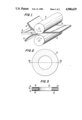
- FIG. 1 is a perspective view of a calendering operation use d in the formation of the high compressiblity composite gasket material of the present invention
- FIG. 2 is a plan view of a gasket formed from the high compressiblity composite gasketing material of the present invention
- FIG. 3 is a sectional view taken along lines A--A of the gasket of FIG. 2;
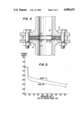
- FIG. 4 is a sectional view of a glass lined pipe joint including the gasket of FIGS. 2 and 3;
- FIG. 5 is a comparison graph of a hot compression test for the high compressiblity composite gasket material of the present invention and a prior art gasket.
- the method of the present invention is directed to the production of a gasket structure having unique properties which render the gasket particularly adapted for use in highly corrosive chemical environments where only minimal flange pressure is available to load the gasket. It has been found that for effective use in these environments, the gasket cannot be a true laminate having a plurality of layers which are adhesively joined, for adhesive joinder of gasket layers in this environment results in possible adhesive contamination problems and layer separation as well as the formation of leak paths between the layers of the laminate.
- a three-layer laminate is first formed which is subsequently united into a unitary gasket structure.
- polytetrafluoroethylene (PTFE) in fine powdered form and suitable glass microballoons are mixed with Stoddard solvent or another suitable liquid in a high-speed mixer to obtain a blend.
- PTFE powder employed in the formation of the blend can be any suitable powder commonly used in the manufacture of PTFE gasketing materials, such, for example, as T-60 fine powder manufactured by DuPont.
- microballoons are added in an amount sufficient to constitute between 15-25% by weight of the blend, and ideally form between 18-21% of the total blend.
- the microballoons have an average particle size of 75 microns, a specific gravity of between 0.20-0.23 and a softening point of 1800° F.
- Microballoons designated as Extendospheres XL100 manufactured by P.A. Industries of Chattanooga, Tenn. are exemplary of the type of microballoons particularly adapted for use in the gasketing material of the present invention.
- the blend is filtered to remove the Stoddard solvent and pressed to form a cake which is then calendered to form sheets.
- Each of these sheets consists of microballoons internally embedded in an unsintered PTFE matrix.
- This third sheet will be at least twice the thickness of the microballoon filled sheets and may be formed by mixing PTFE powder with Stoddard solvent, filtering out the excess liquid and calendering the resultant cake into sheet form to form an unsintered PTFE sheet. If desirable, known fillers such as silica can be mixed with the PTFE in the formation of the third sheet to obtain specific sheet properties in a manner known to the gasketing art, but in a preferred embodiment, this third sheet is an unfilled PTFE sheet.
- the microballoon filled sheets 10 and 12 are positioned on either side of the PTFE sheet 14, and these sheets are calendered between calendering rolls 16 and 18 to form a laminate 20.
- the microballoon filled sheets 10 and 12 are each formed to be within the range of from 20-25% of the overall thickness of the resultant gasket material, while the central PTFE sheet 14 is within the range of from 50-60% of the overall gasket thickness. This is important, for if the sheets 10 and 12 are each formed to be below 20% of the overall gasket thickness, the finished composite sheet looses compressibility, while if they are formed to be above 25%, creep resistance and tensile strength are sacrificed in the finished product.
- the laminate 20 When initially formed, the laminate 20 is unsintered, but once formed, the laminate is sintered by subjecting it to temperatures above the gel point of PTFE.
- This gel point temperature is normally about 650° F., but before this temperature is reached, the PTFE in the sheets 10, 12 and 14 softens and becomes adhesive, and once the gel point is exceeded, a laminate no longer exists as the PTFE in the three original layers is now chemically fused. This eliminates any possibility of separation or delamination in the final gasketing material, as a unitary PTFE gasket has been formed.
- gaskets of any shape may then be formed from the gasketing material, with a round gasket 22 for use in sealing a pipe flange being shown.
- this round gasket has outer surface areas 24 and 25 which contain embedded microballoons 26 and a central area 28 which contains no microballoons but which imparts stability and tensile strength to the gasket.
- the central area 28 is within the range of from 50-60% of the total gasket thickness, while the outer areas 24 and 25 are each within the range of from 20-25% of the total gasket thickness.
- the gasket 22 is shown in place between the flanges of two glass lined pipe sections 30 and 32.
- Each of these pipe sections includes a glass lining 34 which, as illustrated, extends out over the opposed flanges.
- the gasket 22 is positioned between the flanges, and then the flanges are bolted together by bolts 36.
- the surface of the glass lining 34 in glass lined pipes used for chemical applications is somewhat wavy, and this wavy surface must be effectively sealed.
- the bolts 36 load the pipe flanges to an extent sufficient to cause conventional chemically resistant gaskets, such as pure PTFE gaskets, to seal the wavy glass surface, the resultant pressure often destroys or damages the glass lining.
- the gasketing material used is PTFE completely filled with microballoons, tensile strength, resistance to creep relaxation or extrusion, and recovery characteristics are sacrificed in the interest of compressibility.
- the graph of FIG. 5 illustrates the superior resistance to creep relaxation exhibited by the gasket material of the present invention when compared with a PTFE gasket wherein microballoons are mixed throughout the gasket.
- the results indicated by the graph of FIG. 5 were obtained.
- Line A illustrates the creep relaxation experienced by the gasketing material of the present invention at various temperatures
- Line B illustrates a more significant creep relaxation which occurred with the microballoon filled gasketing material.
- the gasketing material of the present invention has an overall tested compressibility in the range of from 45-50% with an average compressibility of 46.6%. Maximum compressibility occurs in the outer areas 24 and 25 of the gasket which constitute from 40-50% of the total gasket thickness. This soft, deformable exterior promotes sealing at low bolt loads, and deformation occurs easily to fill irregularities in flange surfaces. The stable inner area 28 of the gasket minimizes traditional cold flow and provides excellent pressure resistance.
- the improved gasketing material of the present invention operates effectively in corrosive environments where temperatures within the range of from -350° F. to +500° F. are prevalent. Since the gasketing material does not comprise a laminate subject to separation, it can be employed in high vacuum surfaces without the fear of the gasket, or any part of the gasket, being pulled into the vessel or pipeline. The gasketing material operates effectively to seal the uneven surfaces of glass lined pipes without requiring flange pressure in an amount sufficient to damage the glass lining.
Abstract
Description
Claims (9)
Priority Applications (9)
| Application Number | Priority Date | Filing Date | Title |
|---|---|---|---|
| US07/253,185 US4900629A (en) | 1988-10-04 | 1988-10-04 | High compressibility gasket material |
| AU42414/89A AU622221B2 (en) | 1988-10-04 | 1989-09-28 | High compressibility gasket material and method of making the same |
| CA 613969 CA1337873C (en) | 1988-10-04 | 1989-09-28 | High compressibility gasket material and method of making the same |
| JP1255367A JPH02218784A (en) | 1988-10-04 | 1989-10-02 | Highly compressible gasket material and its manufacture |
| DE1989611265 DE68911265T2 (en) | 1988-10-04 | 1989-10-03 | Manufacturing process for sealing material and highly compressible sealing. |
| ES89118272T ES2048807T3 (en) | 1988-10-04 | 1989-10-03 | METHOD FOR FORMING A HIGHLY COMPRESSIBLE PACKAGING MATERIAL AND A SET OF PACKING. |
| AT89118272T ATE98345T1 (en) | 1988-10-04 | 1989-10-03 | MANUFACTURING PROCESS FOR GASKET MATERIAL AND HIGH COMPRESSION SEAL. |
| EP19890118272 EP0365871B1 (en) | 1988-10-04 | 1989-10-03 | Method for forming a gasket material and highly compressible gasket assembly |
| US07/436,797 US4961891A (en) | 1988-10-04 | 1989-11-15 | Method of making high compressibility gasket material |
Applications Claiming Priority (1)
| Application Number | Priority Date | Filing Date | Title |
|---|---|---|---|
| US07/253,185 US4900629A (en) | 1988-10-04 | 1988-10-04 | High compressibility gasket material |
Related Child Applications (1)
| Application Number | Title | Priority Date | Filing Date |
|---|---|---|---|
| US07/436,797 Division US4961891A (en) | 1988-10-04 | 1989-11-15 | Method of making high compressibility gasket material |
Publications (1)
| Publication Number | Publication Date |
|---|---|
| US4900629A true US4900629A (en) | 1990-02-13 |
Family
ID=22959229
Family Applications (1)
| Application Number | Title | Priority Date | Filing Date |
|---|---|---|---|
| US07/253,185 Expired - Lifetime US4900629A (en) | 1988-10-04 | 1988-10-04 | High compressibility gasket material |
Country Status (8)
| Country | Link |
|---|---|
| US (1) | US4900629A (en) |
| EP (1) | EP0365871B1 (en) |
| JP (1) | JPH02218784A (en) |
| AT (1) | ATE98345T1 (en) |
| AU (1) | AU622221B2 (en) |
| CA (1) | CA1337873C (en) |
| DE (1) | DE68911265T2 (en) |
| ES (1) | ES2048807T3 (en) |
Cited By (35)
| Publication number | Priority date | Publication date | Assignee | Title |
|---|---|---|---|---|
| US5032335A (en) * | 1989-07-12 | 1991-07-16 | Mather Seal Company | Manufacture of sealing elements of composite sintered polymeric material |
| AU630276B2 (en) * | 1990-02-15 | 1992-10-22 | Tba Industrial Products Limited | Sheet sealing material |
| US5354611A (en) * | 1990-02-21 | 1994-10-11 | Rogers Corporation | Dielectric composite |
| WO1995000311A1 (en) * | 1993-06-18 | 1995-01-05 | Dalton Robert E | Composite, method and apparatus for making same |
| US5506039A (en) * | 1988-03-08 | 1996-04-09 | Dainippon Ink And Chemicals, Inc. | Sheet molding compounds, production processes therefor, and molded materials therefrom |
| WO1996013676A1 (en) * | 1994-10-31 | 1996-05-09 | W.L. Gore & Associates, Inc. | Rigid sheet polytetrafluoroethylene material |
| US5964465A (en) * | 1996-03-13 | 1999-10-12 | W. L. Gore & Associates, Inc. | Low creep polytetrafluoroethylene form-in-place gasketing elements |
| US6485809B1 (en) | 1999-08-11 | 2002-11-26 | W. L. Gore & Associates Gmbh | Low stress to seal gasket |
| US20030003290A1 (en) * | 2001-02-19 | 2003-01-02 | Hirokazu Hisano | Sealing material in the form of tape, and production thereof |
| US6596369B2 (en) | 2000-04-19 | 2003-07-22 | Sgl Carbon Ag | Flat semi-finished product, component made therefrom and process for the production thereof |
| US6790213B2 (en) | 2002-01-07 | 2004-09-14 | C.R. Bard, Inc. | Implantable prosthesis |
| US20050121859A1 (en) * | 2003-12-05 | 2005-06-09 | Francis Seidel | Gasket of non-rounded shape with installation aids |
| US20060142468A1 (en) * | 2004-12-29 | 2006-06-29 | 3M Innovative Properties Company | Microsphere-filled polytetrafluoroethylene compositions |
| US20070112122A1 (en) * | 1999-08-31 | 2007-05-17 | Friedhelm Stecher | Coating, and a gasket comprising it |
| US20070205566A1 (en) * | 2006-03-02 | 2007-09-06 | Ragsdale Tyler H | Seamless corrugated insert gasket and method of forming the same |
| US20100331468A1 (en) * | 2007-02-06 | 2010-12-30 | Garlock Sealing Technologies Llc | Boron nitride filled ptfe |
| US8691033B1 (en) | 2011-07-06 | 2014-04-08 | Aviation Devices & Electronic Components, Llc | Positioning a workpiece on a sticky gasket |
| US8863625B2 (en) | 2011-06-21 | 2014-10-21 | Aviation Devices & Electronics Components, LLC | Elastomeric gasket squeeze out removal method and kit |
| US20140319776A1 (en) * | 2011-10-14 | 2014-10-30 | Jörg Theike | Seal ring of a mechanical seal assembly having properties extending the running time, and method for the production thereof |
| US20150008650A1 (en) * | 2006-11-06 | 2015-01-08 | Garlock Sealing Technologies Llc | Low-stress molded gasket and method of making same |
| US9016697B2 (en) | 2012-07-10 | 2015-04-28 | Aviation Devices & Electronic Components, Llc | Spacer and gasket assembly for use on an aircraft |
| US20150115548A1 (en) * | 2013-10-29 | 2015-04-30 | Virginia Sealing Products, Inc. | Composite gasket |
| US9072586B2 (en) | 2008-10-03 | 2015-07-07 | C.R. Bard, Inc. | Implantable prosthesis |
| US9303447B1 (en) | 2012-05-15 | 2016-04-05 | Aviation Devices & Electronic Components LLC | Elastomeric gasket for fuel access door of an aircraft wing and a method for making the same |
| US20160144537A1 (en) * | 2013-07-15 | 2016-05-26 | Commissariat à l'énergie atomique et aux énergies alternatives | Method for shaping a plate made of a sintered and restructured polytetrafluoroethylene and applications thereof |
| US9371129B1 (en) | 2011-02-03 | 2016-06-21 | 4M Company | Lightweight aircraft seal material |
| US20160298765A1 (en) * | 2015-04-08 | 2016-10-13 | Aviation Devices & Electronic Components, L.L.C. | Metal mesh with a low electrical resistance conversion coating for use with aircraft structures |
| US9671023B2 (en) | 2012-07-10 | 2017-06-06 | Aviation Devices & Electronic Components, Llc | Spacer and gasket assembly for use on an aircraft |
| US9702464B1 (en) | 2011-10-03 | 2017-07-11 | The Patent Well LLC | Non-planar stick gaskets for receipt between a base and a workpiece |
| US9701388B2 (en) | 2011-05-11 | 2017-07-11 | Aviation Devices & Electronic Components, Llc | Gasket having a pliable resilient body with a perimeter having characteristics different than the body |
| US9751244B2 (en) | 2012-05-15 | 2017-09-05 | The Patent Well LLC | Elastomeric gasket for fuel access door of an aircraft wing and a method for making the same |
| US9769965B2 (en) | 2011-06-17 | 2017-09-19 | Jeffrey D. Busby | Single-sided sticky gasket |
| CN107513271A (en) * | 2017-08-31 | 2017-12-26 | 太仓卡斯特姆新材料有限公司 | A kind of low pressure contracting resistance to deformation rubber seal |
| CN109501424A (en) * | 2018-12-26 | 2019-03-22 | 江苏金由新材料有限公司 | A kind of PTFE composite sealing pad and its preparation process |
| US11879447B2 (en) | 2020-09-09 | 2024-01-23 | Waukesha Bearings Corporation | Composite structures for reciprocating gas compressor systems |
Families Citing this family (4)
| Publication number | Priority date | Publication date | Assignee | Title |
|---|---|---|---|---|
| GB9206960D0 (en) * | 1992-03-31 | 1992-05-13 | Tba Industrial Products Ltd | Sheet sealing material |
| DE19964627B4 (en) * | 1999-08-31 | 2012-08-02 | STE Gesellschaft für Dichtungstechnik mbH | Coating for sealing substrates, especially for production of cylinder head gaskets, contains thermoplastic fluoropolymer and shows decreasing hardness from the coated surface outwards |
| DE10347081A1 (en) * | 2003-10-10 | 2005-05-12 | Frenzelit Werke Gmbh & Co Kg | Gasket material with aggregate for active topographic regulation of force application |
| DE102004041043B3 (en) * | 2004-08-25 | 2006-03-30 | Klinger Ag | Laminated sealing material and process for its production |
Citations (4)
| Publication number | Priority date | Publication date | Assignee | Title |
|---|---|---|---|---|
| US2299805A (en) * | 1941-12-26 | 1942-10-27 | Detroit Gasket & Mfg Company | Packing |
| US2584959A (en) * | 1948-09-14 | 1952-02-05 | Raybestos Manhattan Inc | Cork containing composite sheet material |
| US3524794A (en) * | 1966-08-04 | 1970-08-18 | Minnesota Mining & Mfg | Fluid sealing gasket |
| US3901315A (en) * | 1974-04-11 | 1975-08-26 | Del Norte Technology | Downhole valve |
Family Cites Families (2)
| Publication number | Priority date | Publication date | Assignee | Title |
|---|---|---|---|---|
| US2428771A (en) * | 1944-06-16 | 1947-10-14 | Armstrong Cork Co | Method of making sheet gasket material |
| US3231460A (en) * | 1963-03-21 | 1966-01-25 | Raybestos Manhattan Inc | Sheet material |
-
1988
- 1988-10-04 US US07/253,185 patent/US4900629A/en not_active Expired - Lifetime
-
1989
- 1989-09-28 AU AU42414/89A patent/AU622221B2/en not_active Expired
- 1989-09-28 CA CA 613969 patent/CA1337873C/en not_active Expired - Lifetime
- 1989-10-02 JP JP1255367A patent/JPH02218784A/en active Pending
- 1989-10-03 EP EP19890118272 patent/EP0365871B1/en not_active Expired - Lifetime
- 1989-10-03 DE DE1989611265 patent/DE68911265T2/en not_active Expired - Fee Related
- 1989-10-03 AT AT89118272T patent/ATE98345T1/en not_active IP Right Cessation
- 1989-10-03 ES ES89118272T patent/ES2048807T3/en not_active Expired - Lifetime
Patent Citations (4)
| Publication number | Priority date | Publication date | Assignee | Title |
|---|---|---|---|---|
| US2299805A (en) * | 1941-12-26 | 1942-10-27 | Detroit Gasket & Mfg Company | Packing |
| US2584959A (en) * | 1948-09-14 | 1952-02-05 | Raybestos Manhattan Inc | Cork containing composite sheet material |
| US3524794A (en) * | 1966-08-04 | 1970-08-18 | Minnesota Mining & Mfg | Fluid sealing gasket |
| US3901315A (en) * | 1974-04-11 | 1975-08-26 | Del Norte Technology | Downhole valve |
Cited By (54)
| Publication number | Priority date | Publication date | Assignee | Title |
|---|---|---|---|---|
| US5506039A (en) * | 1988-03-08 | 1996-04-09 | Dainippon Ink And Chemicals, Inc. | Sheet molding compounds, production processes therefor, and molded materials therefrom |
| US5032335A (en) * | 1989-07-12 | 1991-07-16 | Mather Seal Company | Manufacture of sealing elements of composite sintered polymeric material |
| AU630276B2 (en) * | 1990-02-15 | 1992-10-22 | Tba Industrial Products Limited | Sheet sealing material |
| US5354611A (en) * | 1990-02-21 | 1994-10-11 | Rogers Corporation | Dielectric composite |
| WO1995000311A1 (en) * | 1993-06-18 | 1995-01-05 | Dalton Robert E | Composite, method and apparatus for making same |
| US5670189A (en) * | 1993-06-18 | 1997-09-23 | Dalton; Robert E. | Compression molding two or more polytetrafluoroethylene resin layers to form a pressure pad |
| US5846577A (en) * | 1993-06-18 | 1998-12-08 | Dalton; Robert E. | Continuous web press with a polytetrafluoroethylene composite |
| WO1996013676A1 (en) * | 1994-10-31 | 1996-05-09 | W.L. Gore & Associates, Inc. | Rigid sheet polytetrafluoroethylene material |
| US5879789A (en) * | 1994-10-31 | 1999-03-09 | W. L. Gore & Associates, Inc. | Rigid sheet polytetrafluoroethylene gasket |
| US6030694A (en) * | 1994-10-31 | 2000-02-29 | W. L. Gore & Associates, Inc. | Rigid sheet polytetrafluoroethylene material |
| US5964465A (en) * | 1996-03-13 | 1999-10-12 | W. L. Gore & Associates, Inc. | Low creep polytetrafluoroethylene form-in-place gasketing elements |
| US6485809B1 (en) | 1999-08-11 | 2002-11-26 | W. L. Gore & Associates Gmbh | Low stress to seal gasket |
| US20070112122A1 (en) * | 1999-08-31 | 2007-05-17 | Friedhelm Stecher | Coating, and a gasket comprising it |
| US6596369B2 (en) | 2000-04-19 | 2003-07-22 | Sgl Carbon Ag | Flat semi-finished product, component made therefrom and process for the production thereof |
| US20030003290A1 (en) * | 2001-02-19 | 2003-01-02 | Hirokazu Hisano | Sealing material in the form of tape, and production thereof |
| US6790213B2 (en) | 2002-01-07 | 2004-09-14 | C.R. Bard, Inc. | Implantable prosthesis |
| US20040215219A1 (en) * | 2002-01-07 | 2004-10-28 | C.R. Bard, Inc. | Implantable prosthesis |
| US7824420B2 (en) | 2002-01-07 | 2010-11-02 | C.R. Bard, Inc. | Implantable prosthesis |
| US20050121859A1 (en) * | 2003-12-05 | 2005-06-09 | Francis Seidel | Gasket of non-rounded shape with installation aids |
| US20060142468A1 (en) * | 2004-12-29 | 2006-06-29 | 3M Innovative Properties Company | Microsphere-filled polytetrafluoroethylene compositions |
| US7314898B2 (en) * | 2004-12-29 | 2008-01-01 | 3M Innovative Properties Company | Microsphere-filled polytetrafluoroethylene compositions |
| US8066843B2 (en) | 2006-03-02 | 2011-11-29 | Virginia Sealing Products, Inc. | Seamless corrugated insert gasket and method of forming the same |
| US20070205566A1 (en) * | 2006-03-02 | 2007-09-06 | Ragsdale Tyler H | Seamless corrugated insert gasket and method of forming the same |
| US7455301B2 (en) | 2006-03-02 | 2008-11-25 | Virginia Sealing Products, Inc. | Seamless corrugated insert gasket and method of forming the same |
| US20150008650A1 (en) * | 2006-11-06 | 2015-01-08 | Garlock Sealing Technologies Llc | Low-stress molded gasket and method of making same |
| US9618122B2 (en) * | 2006-11-06 | 2017-04-11 | Garlock Sealing Technologies, Llc | Low-stress molded gasket and method of making same |
| US20100331468A1 (en) * | 2007-02-06 | 2010-12-30 | Garlock Sealing Technologies Llc | Boron nitride filled ptfe |
| US9072586B2 (en) | 2008-10-03 | 2015-07-07 | C.R. Bard, Inc. | Implantable prosthesis |
| US10744688B2 (en) | 2011-02-03 | 2020-08-18 | 4M Company | Lightweight material |
| US9925702B2 (en) | 2011-02-03 | 2018-03-27 | 4M Company | Lightweight aircraft seal material |
| US9371129B1 (en) | 2011-02-03 | 2016-06-21 | 4M Company | Lightweight aircraft seal material |
| US11128397B2 (en) | 2011-05-11 | 2021-09-21 | The Patent Well LLC | Methods for making a gasket with a pliable resilient body with a perimeter having characteristics different than the body |
| US10230494B2 (en) | 2011-05-11 | 2019-03-12 | The Patent Well LLC | Gasket having a pliable resilient body with a perimeter having characteristics different than the body |
| US9701388B2 (en) | 2011-05-11 | 2017-07-11 | Aviation Devices & Electronic Components, Llc | Gasket having a pliable resilient body with a perimeter having characteristics different than the body |
| US9769965B2 (en) | 2011-06-17 | 2017-09-19 | Jeffrey D. Busby | Single-sided sticky gasket |
| US8863625B2 (en) | 2011-06-21 | 2014-10-21 | Aviation Devices & Electronics Components, LLC | Elastomeric gasket squeeze out removal method and kit |
| US8691033B1 (en) | 2011-07-06 | 2014-04-08 | Aviation Devices & Electronic Components, Llc | Positioning a workpiece on a sticky gasket |
| US9702464B1 (en) | 2011-10-03 | 2017-07-11 | The Patent Well LLC | Non-planar stick gaskets for receipt between a base and a workpiece |
| US9556960B2 (en) * | 2011-10-14 | 2017-01-31 | Eagleburgmann Germany Gmbh & Co. Kg | Seal ring of a mechanical seal assembly having properties extending the running time, and method for the production thereof |
| US20140319776A1 (en) * | 2011-10-14 | 2014-10-30 | Jörg Theike | Seal ring of a mechanical seal assembly having properties extending the running time, and method for the production thereof |
| US10166703B2 (en) | 2012-05-15 | 2019-01-01 | The Patent Well LLC | Elastomeric gasket with multiple skeletons for placement between two parts of an aircraft and a method for making the same |
| US10603822B2 (en) | 2012-05-15 | 2020-03-31 | The Patent Well LLC | Elastomeric gasket for fuel access door of an aircraft wing and a method for making the same |
| US9303447B1 (en) | 2012-05-15 | 2016-04-05 | Aviation Devices & Electronic Components LLC | Elastomeric gasket for fuel access door of an aircraft wing and a method for making the same |
| US9751244B2 (en) | 2012-05-15 | 2017-09-05 | The Patent Well LLC | Elastomeric gasket for fuel access door of an aircraft wing and a method for making the same |
| US9671023B2 (en) | 2012-07-10 | 2017-06-06 | Aviation Devices & Electronic Components, Llc | Spacer and gasket assembly for use on an aircraft |
| US9016697B2 (en) | 2012-07-10 | 2015-04-28 | Aviation Devices & Electronic Components, Llc | Spacer and gasket assembly for use on an aircraft |
| US20160144537A1 (en) * | 2013-07-15 | 2016-05-26 | Commissariat à l'énergie atomique et aux énergies alternatives | Method for shaping a plate made of a sintered and restructured polytetrafluoroethylene and applications thereof |
| US20150115548A1 (en) * | 2013-10-29 | 2015-04-30 | Virginia Sealing Products, Inc. | Composite gasket |
| US10837555B2 (en) * | 2015-04-08 | 2020-11-17 | Aviation Devices & Electronic Components, L.L.C. | Metal mesh with a low electrical resistance conversion coating for use with aircraft structures |
| US20160298765A1 (en) * | 2015-04-08 | 2016-10-13 | Aviation Devices & Electronic Components, L.L.C. | Metal mesh with a low electrical resistance conversion coating for use with aircraft structures |
| CN107513271A (en) * | 2017-08-31 | 2017-12-26 | 太仓卡斯特姆新材料有限公司 | A kind of low pressure contracting resistance to deformation rubber seal |
| CN109501424A (en) * | 2018-12-26 | 2019-03-22 | 江苏金由新材料有限公司 | A kind of PTFE composite sealing pad and its preparation process |
| CN109501424B (en) * | 2018-12-26 | 2023-09-12 | 江苏金由新材料有限公司 | PTFE composite sealing gasket and preparation process thereof |
| US11879447B2 (en) | 2020-09-09 | 2024-01-23 | Waukesha Bearings Corporation | Composite structures for reciprocating gas compressor systems |
Also Published As
| Publication number | Publication date |
|---|---|
| CA1337873C (en) | 1996-01-02 |
| DE68911265D1 (en) | 1994-01-20 |
| DE68911265T2 (en) | 1994-06-09 |
| AU622221B2 (en) | 1992-04-02 |
| JPH02218784A (en) | 1990-08-31 |
| EP0365871A1 (en) | 1990-05-02 |
| ATE98345T1 (en) | 1993-12-15 |
| ES2048807T3 (en) | 1994-04-01 |
| EP0365871B1 (en) | 1993-12-08 |
| AU4241489A (en) | 1990-04-12 |
Similar Documents
| Publication | Publication Date | Title |
|---|---|---|
| US4900629A (en) | High compressibility gasket material | |
| US4961891A (en) | Method of making high compressibility gasket material | |
| US6092811A (en) | Hybrid gasket | |
| US5421594A (en) | Gasket | |
| US5551706A (en) | Composite gasket for sealing flanges and method for making and using same | |
| US5615896A (en) | Rubber encapsulated vee ring seal | |
| CA2157283C (en) | Wrapped composite gasket material | |
| US4913951A (en) | Fabrication of reinforced PTFE gasketing material | |
| US5492336A (en) | O-ring gasket material and method for making and using same | |
| US4588213A (en) | Threaded pipe connection | |
| US9618122B2 (en) | Low-stress molded gasket and method of making same | |
| EP1203176B1 (en) | Low stress to seal gasket | |
| US20030090067A1 (en) | Rubber and wire mesh ring | |
| EP1917294A1 (en) | Low stress to seal eptfe gasket material | |
| JPH11190432A (en) | High pressure resisting compression breakage and high seal gasket | |
| CA2212158A1 (en) | Creep resistant shaped article of densified expanded polytetrafluoroethylene | |
| AU8032200A (en) | Forged valve stem packing set | |
| US20070176373A1 (en) | Low stress / anti-buckling spiral wound gasket | |
| US6399204B1 (en) | Flexible multi-layer gasketing product | |
| US11268616B2 (en) | Envelope gasket | |
| JP2005337401A (en) | Gasket coated with fluororesin | |
| US20050187325A1 (en) | Silicone gasket compositions | |
| JP2003106456A (en) | Fluororesin covered gasket | |
| AU616200B2 (en) | Flat laminated seal ring | |
| JPH08109368A (en) | Composite gasket |
Legal Events
| Date | Code | Title | Description |
|---|---|---|---|
| AS | Assignment |
Owner name: GARLOCK INC., 1666 DIVISION STREET, PALMYRA, NEW Y Free format text: ASSIGNMENT OF ASSIGNORS INTEREST.;ASSIGNOR:PITOLAJ, STEFAN;REEL/FRAME:004949/0339 Effective date: 19880930 Owner name: GARLOCK INC., 1666 DIVISION STREET, PALMYRA, NEW Y Free format text: ASSIGNMENT OF ASSIGNORS INTEREST;ASSIGNOR:PITOLAJ, STEFAN;REEL/FRAME:004949/0339 Effective date: 19880930 |
|
| STCF | Information on status: patent grant |
Free format text: PATENTED CASE |
|
| CC | Certificate of correction | ||
| AS | Assignment |
Owner name: BANKERS TRUST COMPANY, NEW YORK Free format text: SECURITY INTEREST;ASSIGNORS:COLTEC INDUSTRIES INC.;CFPI INC.;CII HOLDINGS INC.;AND OTHERS;REEL/FRAME:006109/0984 Effective date: 19920401 |
|
| FEPP | Fee payment procedure |
Free format text: PAYOR NUMBER ASSIGNED (ORIGINAL EVENT CODE: ASPN); ENTITY STATUS OF PATENT OWNER: LARGE ENTITY |
|
| FPAY | Fee payment |
Year of fee payment: 4 |
|
| FEPP | Fee payment procedure |
Free format text: PAYOR NUMBER ASSIGNED (ORIGINAL EVENT CODE: ASPN); ENTITY STATUS OF PATENT OWNER: LARGE ENTITY Free format text: PAYER NUMBER DE-ASSIGNED (ORIGINAL EVENT CODE: RMPN); ENTITY STATUS OF PATENT OWNER: LARGE ENTITY |
|
| REMI | Maintenance fee reminder mailed | ||
| FPAY | Fee payment |
Year of fee payment: 8 |
|
| SULP | Surcharge for late payment | ||
| AS | Assignment |
Owner name: COLTEC NORTH CAROLINA, INC., NORTH CAROLINA Free format text: ASSIGNMENT OF ASSIGNORS INTEREST;ASSIGNOR:GARLOCK INC.;REEL/FRAME:009114/0073 Effective date: 19971231 |
|
| FPAY | Fee payment |
Year of fee payment: 12 |
|
| AS | Assignment |
Owner name: COLTEC INDUSTRIES, INC., NORTH CAROLINA Free format text: RELEASE OF SECURTIY INTEREST;ASSIGNOR:BANKER'S TRUST COMPANY;REEL/FRAME:012884/0705 Effective date: 20010731 |
|
| AS | Assignment |
Owner name: GARLOCK SEALING TECHNOLOGIES, LLC, NEW YORK Free format text: ASSIGNMENT OF ASSIGNORS INTEREST;ASSIGNOR:COLTEC NORTH CAROLINA INC.;REEL/FRAME:012928/0231 Effective date: 20011231 |
|
| AS | Assignment |
Owner name: BANK OF AMERICA, N.A., AS AGENT, GEORGIA Free format text: SECURITY INTEREST;ASSIGNOR:GARLOCK SEALING TECHNOLOGIES LLC;REEL/FRAME:013269/0845 Effective date: 20010531 |