US4900503A - Method and apparatus for producing a finned tube from synthetic plastics material - Google Patents
Method and apparatus for producing a finned tube from synthetic plastics material Download PDFInfo
- Publication number
- US4900503A US4900503A US07/227,424 US22742488A US4900503A US 4900503 A US4900503 A US 4900503A US 22742488 A US22742488 A US 22742488A US 4900503 A US4900503 A US 4900503A
- Authority
- US
- United States
- Prior art keywords
- moulding
- production
- tube
- core
- raised portions
- Prior art date
- Legal status (The legal status is an assumption and is not a legal conclusion. Google has not performed a legal analysis and makes no representation as to the accuracy of the status listed.)
- Expired - Fee Related
Links
Images
Classifications
-
- B—PERFORMING OPERATIONS; TRANSPORTING
- B29—WORKING OF PLASTICS; WORKING OF SUBSTANCES IN A PLASTIC STATE IN GENERAL
- B29C—SHAPING OR JOINING OF PLASTICS; SHAPING OF MATERIAL IN A PLASTIC STATE, NOT OTHERWISE PROVIDED FOR; AFTER-TREATMENT OF THE SHAPED PRODUCTS, e.g. REPAIRING
- B29C48/00—Extrusion moulding, i.e. expressing the moulding material through a die or nozzle which imparts the desired form; Apparatus therefor
- B29C48/25—Component parts, details or accessories; Auxiliary operations
- B29C48/88—Thermal treatment of the stream of extruded material, e.g. cooling
- B29C48/90—Thermal treatment of the stream of extruded material, e.g. cooling with calibration or sizing, i.e. combined with fixing or setting of the final dimensions of the extruded article
- B29C48/908—Thermal treatment of the stream of extruded material, e.g. cooling with calibration or sizing, i.e. combined with fixing or setting of the final dimensions of the extruded article characterised by calibrator surface, e.g. structure or holes for lubrication, cooling or venting
-
- B—PERFORMING OPERATIONS; TRANSPORTING
- B29—WORKING OF PLASTICS; WORKING OF SUBSTANCES IN A PLASTIC STATE IN GENERAL
- B29C—SHAPING OR JOINING OF PLASTICS; SHAPING OF MATERIAL IN A PLASTIC STATE, NOT OTHERWISE PROVIDED FOR; AFTER-TREATMENT OF THE SHAPED PRODUCTS, e.g. REPAIRING
- B29C48/00—Extrusion moulding, i.e. expressing the moulding material through a die or nozzle which imparts the desired form; Apparatus therefor
- B29C48/03—Extrusion moulding, i.e. expressing the moulding material through a die or nozzle which imparts the desired form; Apparatus therefor characterised by the shape of the extruded material at extrusion
- B29C48/09—Articles with cross-sections having partially or fully enclosed cavities, e.g. pipes or channels
-
- B—PERFORMING OPERATIONS; TRANSPORTING
- B29—WORKING OF PLASTICS; WORKING OF SUBSTANCES IN A PLASTIC STATE IN GENERAL
- B29C—SHAPING OR JOINING OF PLASTICS; SHAPING OF MATERIAL IN A PLASTIC STATE, NOT OTHERWISE PROVIDED FOR; AFTER-TREATMENT OF THE SHAPED PRODUCTS, e.g. REPAIRING
- B29C48/00—Extrusion moulding, i.e. expressing the moulding material through a die or nozzle which imparts the desired form; Apparatus therefor
- B29C48/03—Extrusion moulding, i.e. expressing the moulding material through a die or nozzle which imparts the desired form; Apparatus therefor characterised by the shape of the extruded material at extrusion
- B29C48/13—Articles with a cross-section varying in the longitudinal direction, e.g. corrugated pipes
-
- B—PERFORMING OPERATIONS; TRANSPORTING
- B29—WORKING OF PLASTICS; WORKING OF SUBSTANCES IN A PLASTIC STATE IN GENERAL
- B29C—SHAPING OR JOINING OF PLASTICS; SHAPING OF MATERIAL IN A PLASTIC STATE, NOT OTHERWISE PROVIDED FOR; AFTER-TREATMENT OF THE SHAPED PRODUCTS, e.g. REPAIRING
- B29C48/00—Extrusion moulding, i.e. expressing the moulding material through a die or nozzle which imparts the desired form; Apparatus therefor
- B29C48/25—Component parts, details or accessories; Auxiliary operations
- B29C48/30—Extrusion nozzles or dies
- B29C48/303—Extrusion nozzles or dies using dies or die parts movable in a closed circuit, e.g. mounted on movable endless support
-
- B—PERFORMING OPERATIONS; TRANSPORTING
- B29—WORKING OF PLASTICS; WORKING OF SUBSTANCES IN A PLASTIC STATE IN GENERAL
- B29C—SHAPING OR JOINING OF PLASTICS; SHAPING OF MATERIAL IN A PLASTIC STATE, NOT OTHERWISE PROVIDED FOR; AFTER-TREATMENT OF THE SHAPED PRODUCTS, e.g. REPAIRING
- B29C48/00—Extrusion moulding, i.e. expressing the moulding material through a die or nozzle which imparts the desired form; Apparatus therefor
- B29C48/25—Component parts, details or accessories; Auxiliary operations
- B29C48/88—Thermal treatment of the stream of extruded material, e.g. cooling
- B29C48/90—Thermal treatment of the stream of extruded material, e.g. cooling with calibration or sizing, i.e. combined with fixing or setting of the final dimensions of the extruded article
- B29C48/901—Thermal treatment of the stream of extruded material, e.g. cooling with calibration or sizing, i.e. combined with fixing or setting of the final dimensions of the extruded article of hollow bodies
- B29C48/902—Thermal treatment of the stream of extruded material, e.g. cooling with calibration or sizing, i.e. combined with fixing or setting of the final dimensions of the extruded article of hollow bodies internally
-
- B—PERFORMING OPERATIONS; TRANSPORTING
- B29—WORKING OF PLASTICS; WORKING OF SUBSTANCES IN A PLASTIC STATE IN GENERAL
- B29C—SHAPING OR JOINING OF PLASTICS; SHAPING OF MATERIAL IN A PLASTIC STATE, NOT OTHERWISE PROVIDED FOR; AFTER-TREATMENT OF THE SHAPED PRODUCTS, e.g. REPAIRING
- B29C2791/00—Shaping characteristics in general
- B29C2791/004—Shaping under special conditions
- B29C2791/006—Using vacuum
-
- B—PERFORMING OPERATIONS; TRANSPORTING
- B29—WORKING OF PLASTICS; WORKING OF SUBSTANCES IN A PLASTIC STATE IN GENERAL
- B29C—SHAPING OR JOINING OF PLASTICS; SHAPING OF MATERIAL IN A PLASTIC STATE, NOT OTHERWISE PROVIDED FOR; AFTER-TREATMENT OF THE SHAPED PRODUCTS, e.g. REPAIRING
- B29C48/00—Extrusion moulding, i.e. expressing the moulding material through a die or nozzle which imparts the desired form; Apparatus therefor
- B29C48/001—Combinations of extrusion moulding with other shaping operations
- B29C48/0018—Combinations of extrusion moulding with other shaping operations combined with shaping by orienting, stretching or shrinking, e.g. film blowing
-
- B—PERFORMING OPERATIONS; TRANSPORTING
- B29—WORKING OF PLASTICS; WORKING OF SUBSTANCES IN A PLASTIC STATE IN GENERAL
- B29K—INDEXING SCHEME ASSOCIATED WITH SUBCLASSES B29B, B29C OR B29D, RELATING TO MOULDING MATERIALS OR TO MATERIALS FOR MOULDS, REINFORCEMENTS, FILLERS OR PREFORMED PARTS, e.g. INSERTS
- B29K2995/00—Properties of moulding materials, reinforcements, fillers, preformed parts or moulds
- B29K2995/0037—Other properties
- B29K2995/0072—Roughness, e.g. anti-slip
-
- B—PERFORMING OPERATIONS; TRANSPORTING
- B29—WORKING OF PLASTICS; WORKING OF SUBSTANCES IN A PLASTIC STATE IN GENERAL
- B29L—INDEXING SCHEME ASSOCIATED WITH SUBCLASS B29C, RELATING TO PARTICULAR ARTICLES
- B29L2023/00—Tubular articles
- B29L2023/003—Tubular articles having irregular or rough surfaces
Definitions
- the invention relates to a method for producing a finned tube from synthetic plastics material in a moulding chamber moving in a direction of production, wherein a molten plastics charge enters the moulding chamber and wherein fins are moulded, which are provided one after another in the direction of production and wherein a tube is formed which is integral with the fins.
- the invention relates furthermore to an apparatus for carrying out this method for producing a finned tube from synthetic plastics material, the tube being provided with raised portions having conveyor faces trailing in a direction of production, with pairs of encircling half moulds which supplement each other on a moulding line to form a mould which moves in a direction of production, the half moulds comprising, defining an outside of a moulding chamber, a mould recess formed alternately by portions for moulding an outside wall of the tube and mould recesses for forming the fins, with, preceding the moulding chamber in the direction of production a nozzle with a nozzle gap and with a core adjacent the nozzle gap and defining an inside of the moulding chamber and widening out in the direction of production towards the moulding recess, forming a draught, with, immediately adjacent the nozzle gap and constructed between the draught of the core and the moulding recess an expansion space with, preceding the expansion space and constructed between the moulding recess and the nozzle, a
- this problem is solved by a method for producing a finned tube from synthetic plastics material, wherein the fins are moulded one after another whereby a fin is formed only after a fin which leads it in the direction of production has already been completely formed and wherein raised portions having conveyor faces trailing in the direction of production are constructed in a surface of the molten plastics charge which is present in the moulding chamber.
- the raised portions which have to be constructed according to the invention already entrain the still almost fluid synthetic plastics material. In the region of these raised portions, it already cools slightly so that there is an increased entraining effect.
- the problems mentioned before are solved by an apparatus of the type indicated, wherein the portions for moulding the outside wall of the tube are provided with conveyor grooves with a conveying surface on a rearward side with regard to the direction of production.
- the inventive features guarantee that the raised portions are moulded on the tube and that the tube is entrained.
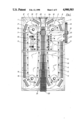
- FIG. 1 is a plan view of an apparatus for producing finned tubes from synthetic plastics material
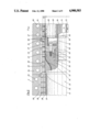
- FIG. 2 is a detail from the apparatus in a horizontal section
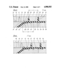
- FIG. 3 to FIG. 6 show a detail from FIG. 2 in various stages of production
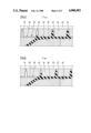
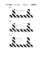
- FIG. 7 to FIG. 9 show details through finned tubes having various types of annular raised portions.
- the apparatus for producing synthetic plastics finned tubes comprises a machine table 1 on which are disposed series of half moulds 2, 2' which are in each case connected to each other to form two so-called chains 3, 3'.
- a connecting member 5 secured by a hinge pin 6 and mounted at the corresponding location on the subsequent half mould 2, 2' likewise by means of such a hinge pin 6.
- the chains 3, 3' which are so formed are, at their rear ends, as viewed in the production direction 4, guided over direction-reversing wheels which serve as so-called feed rollers 7.
- the individual half moulds 2, 2' are, during revolution of the chains 3, 3' corresponding to the directional arrows 8, 8', pivoted into a moulding line 9 in which every two half moulds 2, 2' are combined to form a pair of moulds in which pairs of moulds which follow in sequence in the production direction 4 are located in a tightly adjacent relationship.
- so-called closing rollers 10 are provided which accelerate the bringing together of the (in the production direction 4) rear ends of the half moulds 2, 2'.
- the adjacent half moulds 2, 2' are pressed against each other by guide rollers 11 which are mounted to be rotatable in guide strips 12.
- the feed rollers 7 are mounted on the machine table 1 in such a way as to be rotatable about pivots 13.
- return rollers 14 which serve as direction-reversing wheels and which are mounted to rotate about pivots 15, and about which the chains 3, 3' are deflected and fed back to the feed rollers 7.
- the guide strips 12 with guide rollers 11 end in front of the return rollers 14 by the length of several half moulds 2, 2' so that the half moulds 2, 2' can once again be moved parallel with one another and away from one another transversely to the direction of production 4, before they are pivoted by the return rollers 14.
- a system of teeth 16 Constructed on the top of the half moulds 2, 2' is a system of teeth 16, the two sets of teeth and 16 of the half moulds 2, 2' which are associated with one another in pairs are aligned so that a common drive pinion 17 can engage these teeth 16 from above, pushing the half moulds 2, 2' through the moulding line 9 as a closed mould.
- the drive of this driving pinion 17 is provided in conventional manner by a motor, not shown, through a driving gear wheel 18 which is rotationally rigidly mounted on a shaft 19 which in turn carries the driving pinion 17.
- the shaft 19 is mounted in a bearing pedestal 20 which is supported through spacing prisms 21 in respect of the machine table to which it is rigidly connected by screws 22.
- the apparatus shown is used (see FIG. 2) for producing synthetic plastics tubes 23 having fins 24 extending like closed annular discs radially and over the outer periphery of the tubes 23.
- Such finned tubes have a particularly high crushing strength.
- An extruder is provided of which only the injection nozzle 25 is shown from which, in a manner still to be described in detail hereinafter, molten synthetic plastics material 23a is extruded flowing in a liquid state into the mould formed in the moulding line 9 and in which the tube 23 is constructed with the fins 24.
- the hitherto described apparatus is known, with the exception of the special construction of the tubes 23 with fins 24, being known for example from DE-PS 20 61 027 or EP-PS 0 065 729.
- the half moulds 2, 2' which are disposed in adjacent pairs are cooled in the moulding line 9.
- cooling water passages 26 are constructed in them.
- the moulding recesses 28 which are formed in the half moulds 2, 2a in order to form a moulding chamber 27 are of a shape which is complementary to the outer form of the tube 23 with fins 24. At their radially outermost locations, they are provided with venting ports or slots 29 which discharge into venting passages 30. These are connected to partial vacuum sources, not shown, so that venting and complete filling of the moulding chamber 27 with synthetic plastics material to form the tube 23 with fins 24 is guaranteed.
- the injection moulding nozzle 25 is enclosed by heating means 31 in order to maintain at the necessary temperature the compressed molten synthetic plastics material 23a which is extruded from the extruder and conveyed through the injection moulding nozzle 25. If polyvinyl chloride (PVC) is used as a synthetic plastics material, then this temperature is about 195° to 200° C. Shortly after the commencement of the moulding line, in other words shortly after the region at which the complementary half moulds 2, 2' are rigidly adjacent each other, the outer periphery of the injection moulding nozzle 25 widens out to a cylindrical end portion 32.
- PVC polyvinyl chloride
- the corresponding half mould which happens to be in its closed position is designated by reference numeral 2a in the drawing.
- a safety gap 34 which ensures that the half mould 2a does not come in contact with the cylindrical end portion 32 of the injection moulding nozzle 25. Therefore, the width of the safety gap amounts to between 0.3 and 0.8 mm.
- the injection moulding core 36 comprises, adjacent the nozzle gap 37, a first conical portion 39 (see FIG. 3) which is followed in the production direction 4 by a second conical portion 40.
- the first conical portion 39 forms with the median longitudinal axis 41 of the injection moulding nozzle 25 or of the tube 23 to be produced or of the moulding chamber 27 an angle c of about 5°.
- the second conical portion 40 forms with the axis 41 an angle d of about 3°.
- the transition 42 of the moulding core 36 in the region of the nozzle gap 37 into the first conical portion 39 is rounded off.
- the first conical portion 39 and the second conical portion 40 together form a draught 43 adjacent to which there is another cylindrical portion 44 of the injection moulding core 36.
- a calender head 45 is mounted on the injection moulding core 36, in fact on its cylindrical portion 44.
- the said calender head 45 is pot-shaped, i.e. it has, open in the production direction 4, a cylindrical recess 46 which is lined with a bell-shaped heat insulating means 47 (see FIG. 2).
- screw bolts 48 are used for attachment of the calender head on the injection moulding core 36.
- the calenderhead 45 has in the region adjacent the cylindrical portion 44 of the moulding core 36 a conical portion 49 which widens out in the production direction 4 and which has adjacent to it a cylindrical portion 50.
- the conical portion 49 encloses with the axis 41 an angle e of 3° to 4°.
- the injection moulding core 36 and with it the calenderhead 45 mounted on it are disposed on a core holder 51 being held there by means of an annular nut 52 on a screw thread 53 on the core holder 51.
- a hollow cooling core 54 Concentrically with the axis 41, there extends through the core holder 51 a hollow cooling core 54 on which a cooling core 55 is mounted.
- the said cooling core 55 can be cooled by cooling water which is supplied and discharged through the hollow core 54.
- a corresponding cooling water feed 71 and cooling water discharge 72 are indicated in FIG. 2.
- a conical extension 56 which encloses an angle f of 3° to 4° with the axis 41.
- the cooling core 55 is of cylindrical construction.
- the calenderhead 45 lies flat against the annular end face 57 of the moulding core 36.
- the cooling core 55 has a matching surface 58 which bears on the associated end of the calender head. Consequently, a flow of heat can pass from the moulding core 36 through the calender head 45 to the cooled core 55 which is arrested in the calender head 45 by the bell-shaped heat insulating means 47, since the heat through-flow cross section in the annularly cylindrical part 59 of the calenderhead 45 is relatively small.
- the moulding recess 28 in the half moulds 2, 2a comprises substantially cylindrically constructed portions 60 for moulding the outside wall of the tube and constituting the radially inner face 33 of the corresponding half mould 2, 2a and between which at constant distances there are fin moulding recesses 61 which serve to form the fins 24.
- the portions 60 which mould the outside wall of the tube comprise conveying grooves 62 which extend around the complete cylindrical periphery of the mould portions 60, leading to corresponding annular raised portions 63 on the outer wall of the tube.
- the conveying grooves 62 are on their side which is at the rear or upstream in relation to the production direction 4, defined by a conveying surface 64 which extends substantially radially of the axis 41. Their other boundary surface 65 extends shallow pitched to the axis 41 in the direction of the next conveying surface 64 of the next leading conveying groove 62 in the direction of production 4.
- a finned tube is produced essentially in three stages.
- the highly compressed molten plastics charge 23a is forced through the nozzle gap 37 into the expansion space 38 at the beginning of the moulding chamber 27.
- a fin moulding recess 61 disposed immediately in front of the expansion space 38, in the production direction 4, is filled.
- the air present in the moulding recess 61 is extracted through the vent slots 29 the width of which is so small that molten fluid material cannot penetrate them.
- the fin moulding recess 61 becomes completely filled, as FIG. 4 shows.
- the expansion space 38 fills since for a constant production speed in the production direction 4, i.e.
- the molten plastics charge 23a is required only to produce the cylindrical wall portion of the tube 23.
- the molten material 23a is forced into this fin moulding recess 61, as FIG. 5 shows.
- this moulding recess 61 is filled, so that the expansion space 38 which is left over relative to the half mould 2a and to this moulding recess 61 is again partly emptied of molten plastics charge.
- the molten material is disproportionately cooled so that in this region it is no longer thinly fluid but is very viscous.
- the conveying surfaces 64 of the conveying grooves 62 therefore exert a considerable conveying action on the synthetic plastics material.
- the ratio of the distance f between adjacent fins 24, i.e. adjacent fin moulding recesses 61 to the axial length g of the expansion space 38 is in the range from 1:1 to 1:1.5. In this range, in fact particularly in the bottom part of this range, it is ensured that due to the intensified conveyance of molten plastics batch 23a through the conveying grooves 62, the individual fin moulding recesses 61 are filled one after another. At the end of this first phase, one tube 23 is already available.
- the second phase in moulding the tube 23 takes place over the calenderhead 45 which has a mirror-bright surface in order to calibrate the still warmly-plastic tube 23 so that it later has a clean and smooth inner surface 67.
- this phase 2 over the calenderhead 45, there is a partial cooling of the tube 23, its surface zone of for instance 0.1 mm depth being already cooled to 50° to 60° C.
- the third phase in the manufacture of the tube 23 takes place over the cooling core 55 on which actual calibration of the tube 23 is performed.
- the conical portion 49 of the calenderhead 45 and the conical extension 56 of the cooling core 55 have in each case the task of ensuring a seamless transition of the tube 23 at the corresponding transition point.
- FIGS. 7, 8 and 9 show different annular raised portions 63', 63", 63"', to which adapted mould conveying grooves in the half mould 2a correspond.
- FIG. 7 shows an annular raised portion 63' with a radially downwardly sloping conveying surface 68' to which corresponds an appropriate conveying surface which serves as a boundary to the associated fin moulding recess.
- This conveying surface 68' therefore extends substantially at a right angle to the median longitudinal axis 41 which is not shown in FIGS. 7, 8 and 9.
- FIG. 7 shows an annular raised portion 63' with a radially downwardly sloping conveying surface 68' to which corresponds an appropriate conveying surface which serves as a boundary to the associated fin moulding recess.
- This conveying surface 68' therefore extends substantially at a right angle to the median longitudinal axis 41 which is not
- the transition from the conveying surface 68" or 68"' to the flank 69" or 69"' is acute. This leads to a correspondingly good conveying effect, certainly to a disadvantageous notch effect in the half shell 2a.
- the annular raised portions 63"' are constructed with a lesser radial height and at a smaller distance from one another.
- the fins 25 have a radial height h--measured from the root of the conveying surfaces 68 or flanks 69--which is about 0.035 i, i designating the inside diameter of the tube 23.
- the minimum wall thickness b of the tube corresponds to about 0.015 i.
- the height of the annular raised portions 63 amounts to about 0.12 b to 0.16 b.
Abstract
Description
Claims (14)
Applications Claiming Priority (2)
| Application Number | Priority Date | Filing Date | Title |
|---|---|---|---|
| DE19873725286 DE3725286A1 (en) | 1987-07-30 | 1987-07-30 | METHOD AND DEVICE FOR PRODUCING A RIB TUBE FROM PLASTIC |
| DE3725286 | 1987-07-30 |
Publications (1)
| Publication Number | Publication Date |
|---|---|
| US4900503A true US4900503A (en) | 1990-02-13 |
Family
ID=6332723
Family Applications (1)
| Application Number | Title | Priority Date | Filing Date |
|---|---|---|---|
| US07/227,424 Expired - Fee Related US4900503A (en) | 1987-07-30 | 1988-07-29 | Method and apparatus for producing a finned tube from synthetic plastics material |
Country Status (10)
| Country | Link |
|---|---|
| US (1) | US4900503A (en) |
| EP (1) | EP0301189B2 (en) |
| JP (1) | JPH0624736B2 (en) |
| CN (1) | CN1012721B (en) |
| BR (1) | BR8803766A (en) |
| CA (1) | CA1314678C (en) |
| DE (2) | DE3725286A1 (en) |
| ES (1) | ES2040288T3 (en) |
| FI (1) | FI883531A (en) |
| SU (1) | SU1648244A3 (en) |
Cited By (29)
| Publication number | Priority date | Publication date | Assignee | Title |
|---|---|---|---|---|
| US5002478A (en) * | 1988-09-16 | 1991-03-26 | Lupke Manfred Arno Alfred | Improvements in suction applying mold blocks in pipe forming apparatus |
| US5023029A (en) * | 1988-09-16 | 1991-06-11 | Lupke Manfred Arno Alfred | Method and apparatus for producing pipe with annular ribs |
| US5071173A (en) * | 1989-06-28 | 1991-12-10 | Wilhelm Hegler | Plastic pipe for sewer pipe reconstruction |
| US5141697A (en) * | 1991-04-29 | 1992-08-25 | Miner Enterprises, Inc. | Method of making a segmented polymer energy absorption device |
| AU649108B2 (en) * | 1991-04-08 | 1994-05-12 | Wilhelm Hegler | Apparatus for the production of plastic pipes |
| US5340299A (en) * | 1989-07-12 | 1994-08-23 | Uponor, N.V. | Apparatus for manufacturing ribbed pipes |
| US5393211A (en) * | 1992-07-24 | 1995-02-28 | Wilhelm Hegler | Apparatus for the manufacture of a plastic pipe having transverse profile features |
| US5456589A (en) * | 1992-06-15 | 1995-10-10 | Lupke; Manfred A. A. | Multicavity mold blocks |
| US5516482A (en) * | 1991-06-14 | 1996-05-14 | Corma Inc. | Travelling mold tunnel apparatus for smooth walled pipe |
| US5545369A (en) * | 1993-09-08 | 1996-08-13 | Corma, Inc. | Clamshell corrugators and the like |
| US5693347A (en) * | 1995-09-22 | 1997-12-02 | Hegler Ralph Peter | Apparatus for the manufacture of pipes of thermoplastic plastics having transverse profile features |
| US5707088A (en) * | 1995-08-28 | 1998-01-13 | Contech Construction Products, Inc. | Joint for coupling plastic corrugated pipes |
| US5824351A (en) * | 1996-07-05 | 1998-10-20 | Lupke; Manfred A. A. | Molding apparatus with non-reflective mold tunnels |
| US5851476A (en) * | 1996-05-17 | 1998-12-22 | Miner Enterprises, Inc. | Method of manufacturing a bellowed seal |
| US5976298A (en) * | 1995-02-13 | 1999-11-02 | Ralph-Peter Hegler | Method of producing multilayer thermoplastic pipe |
| US20040047937A1 (en) * | 2002-09-09 | 2004-03-11 | Lupke Manfred A. A. | Molding die for ribbed pipe |
| US7104574B2 (en) | 2000-01-20 | 2006-09-12 | Uponor Eti Company | Corrugated pipe connection joint |
| US20060201567A1 (en) * | 2005-03-14 | 2006-09-14 | Advanced Drainage Systems, Inc. | Corrugated pipe with outer layer |
| US20080203608A1 (en) * | 2007-02-26 | 2008-08-28 | Advanced Drainage Systems, Inc. | Defined Ratio Dual-Wall Pipe Die |
| US20080203607A1 (en) * | 2007-02-26 | 2008-08-28 | Advanced Drainage Systems, Inc. | Pipe Extrusion Die Flow Path Apparatus and Method |
| US20080210327A1 (en) * | 2005-03-14 | 2008-09-04 | Goddard James B | Corrugated pipe with outer layer |
| US20080290538A1 (en) * | 2007-05-23 | 2008-11-27 | Biesenberger Jeffrey J | Extruder ramp-up control system and method |
| US20090127853A1 (en) * | 2007-11-16 | 2009-05-21 | Sutton Gerald S | Three-wall corrugated pipe couplings and methods |
| US20090127852A1 (en) * | 2007-11-16 | 2009-05-21 | Sutton Gerald S | Three-Wall Corrugated Pipe Couplings and Methods |
| US20090200694A1 (en) * | 2008-02-11 | 2009-08-13 | Advanced Drainage Systems, Inc. | Extrusion die vacuum seals and methods |
| US20090295043A1 (en) * | 2008-05-28 | 2009-12-03 | Kolbet Randall A | In-mold punch apparatus and methods |
| US20100090366A1 (en) * | 2008-10-14 | 2010-04-15 | Sutton Gerald S | Apparatus and Method for Pressing an Outer Wall of Pipe |
| DE102009035040A1 (en) | 2009-07-28 | 2011-02-03 | Hegler, Ralph Peter, Dr.-Ing. | Method for continuous production of pipe from thermoplastic material in production direction, involves outwardly applying partial vacuum on tube during production of ring-shaped corrugation in region of trailing flank and/or base portion |
| US20110226464A1 (en) * | 2010-03-16 | 2011-09-22 | Zabelka Scott E | Well head lubricator assembly |
Families Citing this family (8)
| Publication number | Priority date | Publication date | Assignee | Title |
|---|---|---|---|---|
| EP0453647B1 (en) * | 1990-04-27 | 1994-02-23 | REHAU AG + Co | Method of manufacturing profiled elements |
| DE4111229A1 (en) * | 1991-04-08 | 1992-10-15 | Wilhelm Hegler | DEVICE FOR PRODUCING PLASTIC TUBES |
| DE4129855C2 (en) * | 1991-09-07 | 1999-09-16 | Wilhelm Hegler | Process for welding pipes made of thermoplastic material |
| JP2744743B2 (en) * | 1992-12-28 | 1998-04-28 | 日本金銭機械株式会社 | Paper sheet identification device |
| DE4414977A1 (en) * | 1994-04-29 | 1995-11-02 | Wilhelm Hegler | Device for the production of pipes made of thermoplastic material with cross-profiling |
| DE29809587U1 (en) * | 1997-03-12 | 1998-11-26 | Lupke Manfred Arno Alfred | Device for molding plastic parts |
| AU2006316231B2 (en) * | 2005-11-16 | 2012-07-12 | Manufacturing Systems Limited | Improvements in or relating to forming apparatus |
| CA2865601C (en) * | 2014-09-30 | 2022-04-26 | Manfred A. A. Lupke | Mold block return |
Citations (11)
| Publication number | Priority date | Publication date | Assignee | Title |
|---|---|---|---|---|
| US3188690A (en) * | 1959-02-21 | 1965-06-15 | Fraenk Isolierrohr & Metall | Apparatus for the production of corrugated tubes |
| US3349156A (en) * | 1959-02-21 | 1967-10-24 | Fraenk Isolierrohr & Metall | Method for the production of corrugated tubes |
| DE2061027A1 (en) * | 1970-12-11 | 1972-06-22 | Wilhelm Hegler | Device for the production of plastic pipes with transverse profiles |
| DE2362444A1 (en) * | 1973-12-15 | 1975-06-19 | Reifenhaeuser Kg | Smooth bore externally ribbed tube continuously extruded - using smooth mandrel extending from extruder into moving belt mould |
| US3998579A (en) * | 1973-10-22 | 1976-12-21 | Nordstroem Erik G W | Device for producing externally ribbed pipes of plastic |
| US4212618A (en) * | 1978-07-22 | 1980-07-15 | Wilhelm Hegler | Apparatus for the manufacture of transversely contoured tubing from thermoplastic material |
| JPS56130323A (en) * | 1980-03-19 | 1981-10-13 | Mitsui Touatsu Green Shisetsu Kk | Preparation of irregular thickness pipe |
| US4319872A (en) * | 1976-12-01 | 1982-03-16 | Lupke Gerd Paul Heinrich | Apparatus for producing thermoplastic tubing |
| EP0065729A1 (en) * | 1981-05-22 | 1982-12-01 | Wilhelm Hegler | Device for the production of plastics pipes with transverse grooves |
| US4710337A (en) * | 1983-11-15 | 1987-12-01 | Uponor Ab | Method and apparatus for continuously extruding single-wall pipe of plastics or other mouldable material |
| US4721594A (en) * | 1986-03-20 | 1988-01-26 | Uponor N.V. | Method and an apparatus for the production of ribbed pipes |
Family Cites Families (4)
| Publication number | Priority date | Publication date | Assignee | Title |
|---|---|---|---|---|
| US3891007A (en) * | 1972-07-03 | 1975-06-24 | Dayco Corp | Exteriorly corrugated hose of composite materials |
| FR2424123A1 (en) * | 1978-04-24 | 1979-11-23 | Armosig | METHOD AND APPARATUS FOR THE CONTINUOUS MANUFACTURING OF TUBULAR WINGED PROFILES IN SYNTHETIC MATERIAL |
| DE3513708C2 (en) * | 1985-04-12 | 1994-04-21 | Drossbach Gmbh & Co Kg | Extrusion head for producing double-walled plastic pipes with cylindrical inner pipe and cross-corrugated outer pipe |
| FI74654C (en) * | 1986-01-13 | 1988-03-10 | Uponor Nv | ANALYZING OVER FREQUENCY FRAMING PROCESSING. |
-
1987
- 1987-07-30 DE DE19873725286 patent/DE3725286A1/en not_active Ceased
-
1988
- 1988-05-20 DE DE8888108096T patent/DE3880909D1/en not_active Expired - Fee Related
- 1988-05-20 ES ES198888108096T patent/ES2040288T3/en not_active Expired - Lifetime
- 1988-05-20 EP EP88108096A patent/EP0301189B2/en not_active Expired - Lifetime
- 1988-06-22 CA CA000570089A patent/CA1314678C/en not_active Expired - Fee Related
- 1988-07-11 SU SU884356042A patent/SU1648244A3/en active
- 1988-07-25 JP JP63183734A patent/JPH0624736B2/en not_active Expired - Lifetime
- 1988-07-27 FI FI883531A patent/FI883531A/en not_active Application Discontinuation
- 1988-07-29 BR BR8803766A patent/BR8803766A/en not_active Application Discontinuation
- 1988-07-29 CN CN88104682A patent/CN1012721B/en not_active Expired
- 1988-07-29 US US07/227,424 patent/US4900503A/en not_active Expired - Fee Related
Patent Citations (12)
| Publication number | Priority date | Publication date | Assignee | Title |
|---|---|---|---|---|
| US3188690A (en) * | 1959-02-21 | 1965-06-15 | Fraenk Isolierrohr & Metall | Apparatus for the production of corrugated tubes |
| US3349156A (en) * | 1959-02-21 | 1967-10-24 | Fraenk Isolierrohr & Metall | Method for the production of corrugated tubes |
| DE2061027A1 (en) * | 1970-12-11 | 1972-06-22 | Wilhelm Hegler | Device for the production of plastic pipes with transverse profiles |
| US3776679A (en) * | 1970-12-11 | 1973-12-04 | Hegler Wilhelm | Apparatus for the manufacture of plastic tubing of special cross-sectional configuration |
| US3998579A (en) * | 1973-10-22 | 1976-12-21 | Nordstroem Erik G W | Device for producing externally ribbed pipes of plastic |
| DE2362444A1 (en) * | 1973-12-15 | 1975-06-19 | Reifenhaeuser Kg | Smooth bore externally ribbed tube continuously extruded - using smooth mandrel extending from extruder into moving belt mould |
| US4319872A (en) * | 1976-12-01 | 1982-03-16 | Lupke Gerd Paul Heinrich | Apparatus for producing thermoplastic tubing |
| US4212618A (en) * | 1978-07-22 | 1980-07-15 | Wilhelm Hegler | Apparatus for the manufacture of transversely contoured tubing from thermoplastic material |
| JPS56130323A (en) * | 1980-03-19 | 1981-10-13 | Mitsui Touatsu Green Shisetsu Kk | Preparation of irregular thickness pipe |
| EP0065729A1 (en) * | 1981-05-22 | 1982-12-01 | Wilhelm Hegler | Device for the production of plastics pipes with transverse grooves |
| US4710337A (en) * | 1983-11-15 | 1987-12-01 | Uponor Ab | Method and apparatus for continuously extruding single-wall pipe of plastics or other mouldable material |
| US4721594A (en) * | 1986-03-20 | 1988-01-26 | Uponor N.V. | Method and an apparatus for the production of ribbed pipes |
Cited By (43)
| Publication number | Priority date | Publication date | Assignee | Title |
|---|---|---|---|---|
| US5002478A (en) * | 1988-09-16 | 1991-03-26 | Lupke Manfred Arno Alfred | Improvements in suction applying mold blocks in pipe forming apparatus |
| US5023029A (en) * | 1988-09-16 | 1991-06-11 | Lupke Manfred Arno Alfred | Method and apparatus for producing pipe with annular ribs |
| US5071173A (en) * | 1989-06-28 | 1991-12-10 | Wilhelm Hegler | Plastic pipe for sewer pipe reconstruction |
| US5340299A (en) * | 1989-07-12 | 1994-08-23 | Uponor, N.V. | Apparatus for manufacturing ribbed pipes |
| AU649108B2 (en) * | 1991-04-08 | 1994-05-12 | Wilhelm Hegler | Apparatus for the production of plastic pipes |
| US5141697A (en) * | 1991-04-29 | 1992-08-25 | Miner Enterprises, Inc. | Method of making a segmented polymer energy absorption device |
| WO1993025374A1 (en) * | 1991-04-29 | 1993-12-23 | Miner Enterprises, Inc. | Segmented polymer energy absorption device and method of making same |
| US5516482A (en) * | 1991-06-14 | 1996-05-14 | Corma Inc. | Travelling mold tunnel apparatus for smooth walled pipe |
| US5456589A (en) * | 1992-06-15 | 1995-10-10 | Lupke; Manfred A. A. | Multicavity mold blocks |
| US5393211A (en) * | 1992-07-24 | 1995-02-28 | Wilhelm Hegler | Apparatus for the manufacture of a plastic pipe having transverse profile features |
| US5545369A (en) * | 1993-09-08 | 1996-08-13 | Corma, Inc. | Clamshell corrugators and the like |
| US5976298A (en) * | 1995-02-13 | 1999-11-02 | Ralph-Peter Hegler | Method of producing multilayer thermoplastic pipe |
| US5707088A (en) * | 1995-08-28 | 1998-01-13 | Contech Construction Products, Inc. | Joint for coupling plastic corrugated pipes |
| US5862581A (en) * | 1995-08-28 | 1999-01-26 | Contech Construction Products, Inc. | Method for making a joint for a corrugated pipe segment |
| US5693347A (en) * | 1995-09-22 | 1997-12-02 | Hegler Ralph Peter | Apparatus for the manufacture of pipes of thermoplastic plastics having transverse profile features |
| US5851476A (en) * | 1996-05-17 | 1998-12-22 | Miner Enterprises, Inc. | Method of manufacturing a bellowed seal |
| US5824351A (en) * | 1996-07-05 | 1998-10-20 | Lupke; Manfred A. A. | Molding apparatus with non-reflective mold tunnels |
| US7104574B2 (en) | 2000-01-20 | 2006-09-12 | Uponor Eti Company | Corrugated pipe connection joint |
| WO2004022308A1 (en) * | 2002-09-09 | 2004-03-18 | Lupke Manfred Arno Alfred | Molding die for ribbed pipe |
| US6877976B2 (en) | 2002-09-09 | 2005-04-12 | Manfred A. A. Lupke | Molding die for ribbed pipe |
| US20040047937A1 (en) * | 2002-09-09 | 2004-03-11 | Lupke Manfred A. A. | Molding die for ribbed pipe |
| US7484535B2 (en) | 2005-03-14 | 2009-02-03 | Advanced Drainage Systems, Inc. | Corrugated pipe with outer layer |
| US20060201567A1 (en) * | 2005-03-14 | 2006-09-14 | Advanced Drainage Systems, Inc. | Corrugated pipe with outer layer |
| US20080210327A1 (en) * | 2005-03-14 | 2008-09-04 | Goddard James B | Corrugated pipe with outer layer |
| US8733405B2 (en) | 2005-03-14 | 2014-05-27 | Advanced Drainage Systems, Inc. | Corrugated pipe with outer layer |
| US20080203607A1 (en) * | 2007-02-26 | 2008-08-28 | Advanced Drainage Systems, Inc. | Pipe Extrusion Die Flow Path Apparatus and Method |
| US8496460B2 (en) | 2007-02-26 | 2013-07-30 | Advanced Drainage Systems, Inc. | Pipe extrusion die flow path apparatus and method |
| US20080203608A1 (en) * | 2007-02-26 | 2008-08-28 | Advanced Drainage Systems, Inc. | Defined Ratio Dual-Wall Pipe Die |
| US7980841B2 (en) | 2007-02-26 | 2011-07-19 | Advanced Drainage Systems, Inc. | Defined ratio dual-wall pipe die |
| US20080290538A1 (en) * | 2007-05-23 | 2008-11-27 | Biesenberger Jeffrey J | Extruder ramp-up control system and method |
| US20090127852A1 (en) * | 2007-11-16 | 2009-05-21 | Sutton Gerald S | Three-Wall Corrugated Pipe Couplings and Methods |
| US8820800B2 (en) | 2007-11-16 | 2014-09-02 | Advanced Drainage Systems, Inc. | Multi-wall corrugated pipe couplings and methods |
| US8820801B2 (en) | 2007-11-16 | 2014-09-02 | Advanced Drainage System, Inc. | Multi-wall corrugated pipe couplings and methods |
| US20090127853A1 (en) * | 2007-11-16 | 2009-05-21 | Sutton Gerald S | Three-wall corrugated pipe couplings and methods |
| US20090200694A1 (en) * | 2008-02-11 | 2009-08-13 | Advanced Drainage Systems, Inc. | Extrusion die vacuum seals and methods |
| US7988438B2 (en) | 2008-02-11 | 2011-08-02 | Advanced Drainage Systems, Inc. | Extrusion die vacuum seals |
| US20090295043A1 (en) * | 2008-05-28 | 2009-12-03 | Kolbet Randall A | In-mold punch apparatus and methods |
| US8550807B2 (en) | 2008-05-28 | 2013-10-08 | Advanced Drainage Systems, Inc. | In-mold punch apparatus and methods |
| US8114324B2 (en) | 2008-10-14 | 2012-02-14 | Advanced Drainage Systems, Inc. | Apparatus and method for pressing an outer wall of pipe |
| US20100090366A1 (en) * | 2008-10-14 | 2010-04-15 | Sutton Gerald S | Apparatus and Method for Pressing an Outer Wall of Pipe |
| DE102009035040A1 (en) | 2009-07-28 | 2011-02-03 | Hegler, Ralph Peter, Dr.-Ing. | Method for continuous production of pipe from thermoplastic material in production direction, involves outwardly applying partial vacuum on tube during production of ring-shaped corrugation in region of trailing flank and/or base portion |
| US8360140B2 (en) | 2010-03-16 | 2013-01-29 | Miner Elastomer Products Corporation | Well head lubricator assembly |
| US20110226464A1 (en) * | 2010-03-16 | 2011-09-22 | Zabelka Scott E | Well head lubricator assembly |
Also Published As
| Publication number | Publication date |
|---|---|
| EP0301189B1 (en) | 1993-05-12 |
| EP0301189A2 (en) | 1989-02-01 |
| EP0301189A3 (en) | 1990-09-05 |
| FI883531A0 (en) | 1988-07-27 |
| BR8803766A (en) | 1989-02-21 |
| DE3725286A1 (en) | 1989-02-09 |
| CN1012721B (en) | 1991-06-05 |
| JPS6442210A (en) | 1989-02-14 |
| ES2040288T3 (en) | 1993-10-16 |
| EP0301189B2 (en) | 1998-08-26 |
| FI883531A (en) | 1989-01-31 |
| CA1314678C (en) | 1993-03-23 |
| SU1648244A3 (en) | 1991-05-07 |
| CN1031047A (en) | 1989-02-15 |
| DE3880909D1 (en) | 1993-06-17 |
| JPH0624736B2 (en) | 1994-04-06 |
Similar Documents
| Publication | Publication Date | Title |
|---|---|---|
| US4900503A (en) | Method and apparatus for producing a finned tube from synthetic plastics material | |
| US5992469A (en) | Composite pipe with integral socket | |
| US5472659A (en) | Method for continuously manufacturing compound corrugated pipe having smooth portions | |
| KR900004432B1 (en) | Extrusion dic for two-ply plastic tubing | |
| US5320797A (en) | Method and apparatus for the continuous manufacture of a compound pipe with a pipe socket | |
| US4937035A (en) | Method for manufacturing large-volume hollow bodies of plastics material having multiple-layer walls | |
| US2803041A (en) | Extrusion of plastic materials | |
| AU601317B2 (en) | Directed flow die assembly | |
| US5000900A (en) | Twin screw extruder | |
| JPH0253221B2 (en) | ||
| US4859165A (en) | Extruder for food | |
| HU206849B (en) | Apparatus and method for producing ribbed plastic tubes of plain internal surface | |
| US5453238A (en) | Extrusion apparatus and method of extrusion for raw rubber mixes | |
| US3416190A (en) | Diehead | |
| US6045347A (en) | Apparatus for the production of plastic compound pipes | |
| FI56788C (en) | REFRIGERATING THERMAL PLASTIC MATERIAL AND THERMAL PLASTIC MATERIAL | |
| US6773253B2 (en) | Device for producing profiled tubes consisting of synthetic material | |
| US3298064A (en) | Apparatus for molding synthetic resin bodies | |
| US4017244A (en) | Device for the molding of corrugated pipe from extruded thermoplastic materials | |
| US3905588A (en) | Method and apparatus for plasticating polymers | |
| CA2240621C (en) | Process and apparatus for the production of corrugated plastic tubes | |
| US20030072837A1 (en) | Apparatus for the manufacture of corrugated plastic pipes | |
| US4798696A (en) | Method for extrusion of plastic tubes, and an apparatus for carrying out said method | |
| EP1459867B1 (en) | A mixing device for extruders | |
| US3689189A (en) | Screw for an extruding device and a device including said screw |
Legal Events
| Date | Code | Title | Description |
|---|---|---|---|
| AS | Assignment |
Owner name: HEGLER, WILHELM, GERMANY Free format text: ASSIGNMENT OF ASSIGNORS INTEREST.;ASSIGNORS:HEGLER, WILHELM;HEGLER, RALPH-PETER;REEL/FRAME:005016/0442 Effective date: 19880614 |
|
| FEPP | Fee payment procedure |
Free format text: PAYOR NUMBER ASSIGNED (ORIGINAL EVENT CODE: ASPN); ENTITY STATUS OF PATENT OWNER: SMALL ENTITY |
|
| FPAY | Fee payment |
Year of fee payment: 4 |
|
| FPAY | Fee payment |
Year of fee payment: 8 |
|
| REMI | Maintenance fee reminder mailed | ||
| LAPS | Lapse for failure to pay maintenance fees | ||
| STCH | Information on status: patent discontinuation |
Free format text: PATENT EXPIRED DUE TO NONPAYMENT OF MAINTENANCE FEES UNDER 37 CFR 1.362 |
|
| FP | Lapsed due to failure to pay maintenance fee |
Effective date: 20020213 |