US4900314A - Collapse-resistant tubing for medical use - Google Patents
Collapse-resistant tubing for medical use Download PDFInfo
- Publication number
- US4900314A US4900314A US07/151,030 US15103088A US4900314A US 4900314 A US4900314 A US 4900314A US 15103088 A US15103088 A US 15103088A US 4900314 A US4900314 A US 4900314A
- Authority
- US
- United States
- Prior art keywords
- tube
- collapse
- spiral
- resistant
- catheter
- Prior art date
- Legal status (The legal status is an assumption and is not a legal conclusion. Google has not performed a legal analysis and makes no representation as to the accuracy of the status listed.)
- Expired - Fee Related
Links
Images

Classifications
-
- F—MECHANICAL ENGINEERING; LIGHTING; HEATING; WEAPONS; BLASTING
- F16—ENGINEERING ELEMENTS AND UNITS; GENERAL MEASURES FOR PRODUCING AND MAINTAINING EFFECTIVE FUNCTIONING OF MACHINES OR INSTALLATIONS; THERMAL INSULATION IN GENERAL
- F16L—PIPES; JOINTS OR FITTINGS FOR PIPES; SUPPORTS FOR PIPES, CABLES OR PROTECTIVE TUBING; MEANS FOR THERMAL INSULATION IN GENERAL
- F16L11/00—Hoses, i.e. flexible pipes
- F16L11/04—Hoses, i.e. flexible pipes made of rubber or flexible plastics
- F16L11/12—Hoses, i.e. flexible pipes made of rubber or flexible plastics with arrangements for particular purposes, e.g. specially profiled, with protecting layer, heated, electrically conducting
-
- A—HUMAN NECESSITIES
- A61—MEDICAL OR VETERINARY SCIENCE; HYGIENE
- A61M—DEVICES FOR INTRODUCING MEDIA INTO, OR ONTO, THE BODY; DEVICES FOR TRANSDUCING BODY MEDIA OR FOR TAKING MEDIA FROM THE BODY; DEVICES FOR PRODUCING OR ENDING SLEEP OR STUPOR
- A61M25/00—Catheters; Hollow probes
- A61M25/0043—Catheters; Hollow probes characterised by structural features
- A61M25/0054—Catheters; Hollow probes characterised by structural features with regions for increasing flexibility
-
- A—HUMAN NECESSITIES
- A61—MEDICAL OR VETERINARY SCIENCE; HYGIENE
- A61M—DEVICES FOR INTRODUCING MEDIA INTO, OR ONTO, THE BODY; DEVICES FOR TRANSDUCING BODY MEDIA OR FOR TAKING MEDIA FROM THE BODY; DEVICES FOR PRODUCING OR ENDING SLEEP OR STUPOR
- A61M25/00—Catheters; Hollow probes
- A61M25/0021—Catheters; Hollow probes characterised by the form of the tubing
- A61M25/0023—Catheters; Hollow probes characterised by the form of the tubing by the form of the lumen, e.g. cross-section, variable diameter
- A61M25/0026—Multi-lumen catheters with stationary elements
- A61M2025/004—Multi-lumen catheters with stationary elements characterized by lumina being arranged circumferentially
Definitions
- This invention relates to tubing for medical usage and more particularly to small diameter tubing which are collapse resistant.
- Collapse resistant tubing particularly for air delivery in medical procedures typically comprises a single lumen tube the wall of which has a crenellated cross section imparting to it a corrugated geometry.
- Such tubes are in widespread use, they are difficult to make small, they do crimp, they do cause turbulence in the flow of material through them, and they cannot be made in an integral multilumen configuration.
- the invention is based on the realization that all the advantages of a corrugated tube can be retained while all the disadvantages can be eliminated by an alternative tube configuration.
- the alternative tube configuration comprises, in one embodiment, a single center lumen with, for example, a smooth circular wall and a second tube attached to the outer surface of that wall and following a spiral path about that wall.
- the second tube not only provides rigidity, but resists crimping, avoids turbulence and provides a secondary path or lumen which may be used, for example, to withdraw fluids.
- the second tube is produced by coextrusion techniques where a rotating die delivers a second extrudate downstream of a previously extruded smooth outer wall of the center tube.
- the center tube itself can be made of a multilumen configuration, a structure not possible with prior are collapse-resistant tubing.
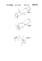
- FIGS. 1 and 2 are schematic representations of collapse resistant catheters in accordance with the principles of this invention.
- FIG. 3 is a schematic representation of a prior art collapse-resistant tube for air delivery.
- FIGS. 4, 5, and 6 are cross sections of spiral shaped second tubes for providing collapse-resistance.
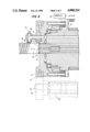
- FIGS. 7 and 8 are end and cross section views of portions of extrusion apparatus for making spiral-shaped, collapse-resistant catheters.
- FIG. 1 shows a collapse-resistant catheter 10 in accordance with the principles of this invention.
- Cathether 10 includes a single lumen center tube 11 and a spiral-shaped, outer tube 12.
- Tube 11 has a significantly larger internal diameter than does tube 12.
- the relative sizes of tubes 11 and 12 may correspond, for example, to the size of the minimum distance between the recesses between the corrugations of a prior art collapse-resistant tube and the depth of the corrugations respectively.
- the structure of FIG. 1 has been found to resist collapse to a level greater than that of commercially available crenellated, collapse-resistant tubes. Specifically, during testing, prior art collapse-resistant tubes exhibited kinks under pressures from which tubes of the type shown in FIG. 1 completely recovered.
- FIG. 2 shows a catheter having a tube 20 of a multilumen configuration including lumens 21, 22, and 23. Such lumens can be used in traditional fashion to provide access for optical fibers, guide wires, etc.
- the catheter also includes spiral tube 25 which provides a collapse-resistant function as does tube 12 of FIG. 1.
- Spiral tube 12 or 25 provides for an additional function as well. It permits the introduction of an additional fluid if a fixture for accessing the tube is attached.
- FIG. 3 shows conventional fittings 30 and 31 for the proximal and distal ends respectively of a prior art corrugated air delivery tube 32.
- the fixtures shown provide for the input of air at input port 34 and for insertion of an additional tube at input port 35.
- a fitting of the type identified at 30 in FIG. 3 is adapted so that input port 35 would communicate with spiral tube 12 of FIG. 1.
- the fitting is adapted to access multilumen catheters with the structure of FIG. 2 in a manner similar to fixtures for accessing presently available multilumen catheters.
- Collapse-resistant tubing employing spiral external tubes can be made of a size to permit insertion into the human body.
- the center tube single or multilumen can be made with a diameter of 0.125 inch with the spiral tube being one-eighth that diameter or 0.009 inch. It is contemplated that the spiral would be tightly wound about the center tube for applications where insertion into the body is necessary. But the ideal slope for the spiral is expected to be different for different applications.
- FIGS. 4, 5 and 6 show spiral tubes 41, 51, and 61 of rectangular, oval, and rectangular-solid configurations respectively.
- Spiral tubes are fabricated at the same time a center tube is extruded by a coextrusion procedure employing a second extrusion die which travels in a circular path about the main extrusion die which configures the center tube.
- the second extrusion die is mounted on the face of a plate which is driven externally conveniently by a perimeter gear arrangement.
- the plate is adapted to receive the main die along a center aperture and to rotate the second die along an orbital path to coextrude the spiral tube along the wall of the center tube.
- the angular velocity of the second (planetary) die and the rate of extrusion of the center tube determines the slope of the spiral.
- FIG. 7 shows a circular plate 70 adapted to receive a first extrusion die 72 along its center axis and to receive a planetary (second) die 73 in an orbital position.
- Rotation of the plate as extrudate is metered into a center tube along an orthogonal path aligned with the axis of the plate results in the delivery of extrudate to a die which follows a spiral path with respect to the advancing center tube.
- the extrudate is delivered to the rotating plate into a circular channel located at the position of imaginary circle 71 in the underside of plate 70 as viewed in FIG. 7.
- An extrusion input port (not shown) moves extrudate in conventional fashion to the circular channel to provide a continuous stream of extrudate to the channel as the plate (70) rotates.
- the second die 73 is secured to plate 70 at aperture 74.
- Aperture 74 has an internal thread and communicates with the circular channel.
- the second die is secured to plate 70 at aperture 74 and thus is adapted to communicate with the circular channel.
- the second die includes a center channel and pin arrangement adapted to configure the extrudate into the spiral tube in conventional fashion.
- FIG. 8 shows plate 70 as well as the main and second dies in cross section.
- Plate 70 is shown positioned vertically with the main die, designated 75, aligned horizontally along the center axis 76 of the plate as viewed in FIG. 8.
- the planetary or second die 73 has a t-shaped geometry the base of which is secured at 74 so that extrudate in a supply channel 81 is fed through die 73 regardless of the position of die 73 with respect to the cirdular channel at circle 71 of FIG. 7.
- the extrudate exits die 73 at an exit port 84 and forms spiral 85 as the, now formed, center tube moves to the left as indicate by arrow 86 in FIG. 8.
- Die 73 includes a pin-receiving port 87 adapted to receive a pin 88. With pin 87 in place, the spiral 85 is formed as a tube in conventional fashion. In the absence of pin 87, spiral 85 is formed as a solid. The shape of the spiral is controlled by the shape of the exit port 84 of die 73. The slope of the spiral is determined by the rate at which the center tube is advanced along axis 76 to the left as indicated by arrow 86.
- the periphery of plate 70 includes a gear arrangement indicated at 91.
- the gear arrangement mates with gear 92 which is mounted on shaft 93.
- Shaft 93 is driven by motor 95.
- Controller 96 is adapted to coordinate the rotation of plate 70, the extrudate delivery and the rotation of die 73.
- the center tube, or a single lumen therein may be made of an abrasion-resistant material and the second tube or other lumen may be made of biocompatible material.
Abstract
Description
Claims (6)
Priority Applications (1)
| Application Number | Priority Date | Filing Date | Title |
|---|---|---|---|
| US07/151,030 US4900314A (en) | 1988-02-01 | 1988-02-01 | Collapse-resistant tubing for medical use |
Applications Claiming Priority (1)
| Application Number | Priority Date | Filing Date | Title |
|---|---|---|---|
| US07/151,030 US4900314A (en) | 1988-02-01 | 1988-02-01 | Collapse-resistant tubing for medical use |
Publications (1)
| Publication Number | Publication Date |
|---|---|
| US4900314A true US4900314A (en) | 1990-02-13 |
Family
ID=22537043
Family Applications (1)
| Application Number | Title | Priority Date | Filing Date |
|---|---|---|---|
| US07/151,030 Expired - Fee Related US4900314A (en) | 1988-02-01 | 1988-02-01 | Collapse-resistant tubing for medical use |
Country Status (1)
| Country | Link |
|---|---|
| US (1) | US4900314A (en) |
Cited By (78)
| Publication number | Priority date | Publication date | Assignee | Title |
|---|---|---|---|---|
| WO1991012836A1 (en) * | 1990-02-23 | 1991-09-05 | New England Deaconess Hospital Corporation | Apparatus and method for central venous catheterization |
| US5125909A (en) * | 1989-06-14 | 1992-06-30 | Richard Wolf Gmbh | Flexible tubular channel with external supporting ridges |
| US5222949A (en) * | 1991-07-23 | 1993-06-29 | Intermed, Inc. | Flexible, noncollapsible catheter tube with hard and soft regions |
| US5226899A (en) * | 1990-03-26 | 1993-07-13 | Becton, Dickinson And Company | Catheter tubing of controlled in vivo softening |
| US5338295A (en) * | 1991-10-15 | 1994-08-16 | Scimed Life Systems, Inc. | Dilatation catheter with polyimide-encased stainless steel braid proximal shaft |
| US5383467A (en) * | 1992-11-18 | 1995-01-24 | Spectrascience, Inc. | Guidewire catheter and apparatus for diagnostic imaging |
| US5389091A (en) * | 1991-03-07 | 1995-02-14 | C. R. Bard, Inc. | Site-selective durability-enhanced catheter and methods of manufacturing and using same |
| US5415634A (en) * | 1990-08-23 | 1995-05-16 | Devices For Vascular Intervention, Inc. | Catheter having helical inflation lumen |
| US5439000A (en) * | 1992-11-18 | 1995-08-08 | Spectrascience, Inc. | Method of diagnosing tissue with guidewire |
| WO1996008287A1 (en) * | 1994-09-13 | 1996-03-21 | Hakky Said I | Collapsible catheter |
| US5533987A (en) * | 1992-04-09 | 1996-07-09 | Scimed Lifesystems, Inc. | Dilatation catheter with polymide encased stainless steel braid proximal shaft |
| US5762631A (en) * | 1995-07-14 | 1998-06-09 | Localmed, Inc. | Method and system for reduced friction introduction of coaxial catheters |
| US5961765A (en) * | 1994-09-20 | 1999-10-05 | Schneider (Europe) A. G. | Method of making a catheter |
| US5976120A (en) * | 1997-05-05 | 1999-11-02 | Micro Therapeutics, Inc. | Single segment microcatheter |
| US6027477A (en) * | 1993-10-27 | 2000-02-22 | Schneider (Europe) A.G. | Catheter with multilayer tube |
| US6059768A (en) * | 1997-08-06 | 2000-05-09 | Friedman; David J. | Coded intravenous tubing |
| US6134003A (en) * | 1991-04-29 | 2000-10-17 | Massachusetts Institute Of Technology | Method and apparatus for performing optical measurements using a fiber optic imaging guidewire, catheter or endoscope |
| US6165166A (en) * | 1997-04-25 | 2000-12-26 | Schneider (Usa) Inc. | Trilayer, extruded medical tubing and medical devices incorporating such tubing |
| US6171296B1 (en) | 1998-04-28 | 2001-01-09 | Microtherapeutics, Inc. | Flow directed catheter |
| US6213995B1 (en) | 1999-08-31 | 2001-04-10 | Phelps Dodge High Performance Conductors Of Sc And Ga, Inc. | Flexible tubing with braided signal transmission elements |
| US6299591B1 (en) * | 1995-06-02 | 2001-10-09 | Surgical Design Corporation | Phacoemulsification handpiece, sleeve, and tip |
| US6319228B1 (en) | 1996-04-26 | 2001-11-20 | Schneider (Europe) A.G. | Multilayer interventional catheter |
| US6421164B2 (en) | 1991-04-29 | 2002-07-16 | Massachusetts Institute Of Technology | Interferometeric imaging with a grating based phase control optical delay line |
| US20020116047A1 (en) * | 1996-11-04 | 2002-08-22 | Vardi Gil M. | Extendible stent apparatus and method for deploying the same |
| US6445939B1 (en) | 1999-08-09 | 2002-09-03 | Lightlab Imaging, Llc | Ultra-small optical probes, imaging optics, and methods for using same |
| US6485413B1 (en) | 1991-04-29 | 2002-11-26 | The General Hospital Corporation | Methods and apparatus for forward-directed optical scanning instruments |
| US20020177804A1 (en) * | 1992-08-13 | 2002-11-28 | Radiant Medical, Inc. | Heat transfer catcheters methods of making and using same |
| US6501551B1 (en) | 1991-04-29 | 2002-12-31 | Massachusetts Institute Of Technology | Fiber optic imaging endoscope interferometer with at least one faraday rotator |
| GB2379996A (en) * | 2001-06-05 | 2003-03-26 | Tayside Flow Technologies Ltd | Flow means |
| US6540734B1 (en) * | 2000-02-16 | 2003-04-01 | Advanced Cardiovascular Systems, Inc. | Multi-lumen extrusion tubing |
| US6596020B2 (en) | 1996-11-04 | 2003-07-22 | Advanced Stent Technologies, Inc. | Method of delivering a stent with a side opening |
| US20030181923A1 (en) * | 1996-11-04 | 2003-09-25 | Gil Vardi | Methods for deploying stents in bifurcations |
| US20030195606A1 (en) * | 1999-09-23 | 2003-10-16 | Advanced Stent Technologies, Inc., A Delaware Corporation | Bifurcation stent system and method |
| US6659977B2 (en) | 1993-10-27 | 2003-12-09 | Schneider (Europe) A.G. | Multilayer interventional catheter |
| US20040015227A1 (en) * | 1996-11-04 | 2004-01-22 | Gil Vardi | Extendible stent apparatus |
| US6682536B2 (en) | 2000-03-22 | 2004-01-27 | Advanced Stent Technologies, Inc. | Guidewire introducer sheath |
| US6689156B1 (en) | 1999-09-23 | 2004-02-10 | Advanced Stent Technologies, Inc. | Stent range transducers and methods of use |
| US6692483B2 (en) | 1996-11-04 | 2004-02-17 | Advanced Stent Technologies, Inc. | Catheter with attached flexible side sheath |
| US6716252B2 (en) | 2000-06-30 | 2004-04-06 | Wit Ip Corporation | Prostatic stent with localized tissue engaging anchoring means and methods for inhibiting obstruction of the prostatic urethra |
| US20040133268A1 (en) * | 1998-01-14 | 2004-07-08 | Advanced Stent Technologies, Inc. | Extendible stent apparatus |
| US20040138737A1 (en) * | 1996-11-04 | 2004-07-15 | Advanced Stent Technologies, Inc. | Stent with protruding branch portion for bifurcated vessels |
| US20040153136A1 (en) * | 2001-05-18 | 2004-08-05 | Vardi Gil M. | Dual guidewire exchange catheter system |
| EP1475031A1 (en) * | 2003-05-05 | 2004-11-10 | STM Medizintechnik Starnberg GmbH | Endoscope shaft |
| US6835203B1 (en) | 1996-11-04 | 2004-12-28 | Advanced Stent Technologies, Inc. | Extendible stent apparatus |
| US20050060027A1 (en) * | 1999-01-13 | 2005-03-17 | Advanced Stent Technologies, Inc. | Catheter balloon systems and methods |
| US20050065596A1 (en) * | 2002-07-24 | 2005-03-24 | Xufan Tseng | Stents capable of controllably releasing histone deacetylase inhibitors |
| US6884258B2 (en) | 1999-06-04 | 2005-04-26 | Advanced Stent Technologies, Inc. | Bifurcation lesion stent delivery using multiple guidewires |
| US20050102019A1 (en) * | 2003-11-12 | 2005-05-12 | Advanced Stent Technologies, Inc. | Catheter balloon systems and methods |
| US20050102023A1 (en) * | 2003-08-21 | 2005-05-12 | Amnon Yadin | Stent with protruding branch portion for bifurcated vessels |
| US20050245941A1 (en) * | 1999-12-06 | 2005-11-03 | Vardi Gil M | Catheter with attached flexible side sheath |
| US20060217682A1 (en) * | 1998-10-23 | 2006-09-28 | Scimed Life Systems, Inc. | Catheter having improved bonding region |
| US20070103926A1 (en) * | 2005-11-07 | 2007-05-10 | Nancy Brooks | Lighted tubing |
| US20070135904A1 (en) * | 2005-12-14 | 2007-06-14 | Tracee Eidenschink | Telescoping bifurcated stent |
| US20070135903A1 (en) * | 2005-12-14 | 2007-06-14 | Daniel Gregorich | Connectors for bifurcated stent |
| US20070203562A1 (en) * | 2006-02-22 | 2007-08-30 | Andrzej Malewicz | Marker arrangement for bifurcation catheter |
| US20070208414A1 (en) * | 2006-03-06 | 2007-09-06 | Shawn Sorenson | Tapered strength rings on a bifurcated stent petal |
| US20070208300A1 (en) * | 2006-03-01 | 2007-09-06 | Applied Medical Resources Corporation | Gas insufflation and suction/irrigation tubing |
| US20070233233A1 (en) * | 2006-03-31 | 2007-10-04 | Boston Scientific Scimed, Inc | Tethered expansion columns for controlled stent expansion |
| US20080046046A1 (en) * | 1993-02-10 | 2008-02-21 | Radiant Medical, Inc. | Method for endovascular management of body temperature |
| US7341598B2 (en) | 1999-01-13 | 2008-03-11 | Boston Scientific Scimed, Inc. | Stent with protruding branch portion for bifurcated vessels |
| US20080255581A1 (en) * | 1999-06-04 | 2008-10-16 | Boston Scientific Scimed, Inc. | Short sleeve stent delivery catheter and methods |
| US20090162585A1 (en) * | 2007-12-21 | 2009-06-25 | Cook Incorporated | Jejunal feeding tube |
| US20090171430A1 (en) * | 2007-12-31 | 2009-07-02 | Boston Scientific Scimed, Inc. | Bifurcation stent delivery system and methods |
| US7655030B2 (en) | 2003-07-18 | 2010-02-02 | Boston Scientific Scimed, Inc. | Catheter balloon systems and methods |
| US20100114018A1 (en) * | 2007-11-14 | 2010-05-06 | Boston Scientific Scimed, Inc. | Balloon bifurcated lumen treatment |
| US20100114019A1 (en) * | 2008-06-05 | 2010-05-06 | Boston Scientific Scimed, Inc. | Deflatable bifurcated device |
| US20100269830A1 (en) * | 2009-04-24 | 2010-10-28 | Sage Products, Inc. | Fluid Removing Apparatus for Respiratory Tract |
| US20120095291A1 (en) * | 2009-07-06 | 2012-04-19 | Kiyokazu Nakajima | Endoscope overtube |
| US8216498B2 (en) | 2008-09-10 | 2012-07-10 | Boston Scientific Scimed, Inc. | Catheter having a coextruded fluoropolymer layer |
| US8377108B2 (en) | 2008-06-02 | 2013-02-19 | Boston Scientific Scimed, Inc. | Staggered two balloon bifurcation catheter assembly and methods |
| US8486134B2 (en) | 2007-08-01 | 2013-07-16 | Boston Scientific Scimed, Inc. | Bifurcation treatment system and methods |
| US20140323964A1 (en) * | 2013-03-16 | 2014-10-30 | Clph, Llc | Steerable catheters and methods for making them |
| US9308051B2 (en) | 2011-11-15 | 2016-04-12 | Smiths Medical Asd, Inc. | Illuminated tubing set |
| US9308323B2 (en) | 2011-11-15 | 2016-04-12 | Smiths Medical Asd, Inc. | Systems and methods for illuminated medical tubing detection and management indicating a characteristic of at least one infusion pump |
| US20170080180A1 (en) * | 2010-09-01 | 2017-03-23 | Cathway Medical (2012) Ltd. | Catheter with asymmetric cross-section |
| US10065015B2 (en) | 2014-09-01 | 2018-09-04 | Clph, Llc | Catheter devices and methods for making them |
| US10118334B2 (en) | 2016-07-14 | 2018-11-06 | Custom Wire Technologies, Inc. | Wire-reinforced tubing and method of making the same |
| US10124145B2 (en) | 2014-09-21 | 2018-11-13 | Clph, Llc | Catheter devices and methods for making them |
Citations (4)
| Publication number | Priority date | Publication date | Assignee | Title |
|---|---|---|---|---|
| US1596754A (en) * | 1923-10-30 | 1926-08-17 | Judson D Moschelle | Reenforced tubing |
| US3034510A (en) * | 1959-01-02 | 1962-05-15 | British Oxygen Co Ltd | Catheters |
| US3963856A (en) * | 1974-11-25 | 1976-06-15 | Steward Plastics, Inc. | Flexible, corrugated, plastic tubing having conductive helical bead |
| US4498473A (en) * | 1982-12-07 | 1985-02-12 | Gereg Gordon A | Variable stiffness tracheal tube |
-
1988
- 1988-02-01 US US07/151,030 patent/US4900314A/en not_active Expired - Fee Related
Patent Citations (4)
| Publication number | Priority date | Publication date | Assignee | Title |
|---|---|---|---|---|
| US1596754A (en) * | 1923-10-30 | 1926-08-17 | Judson D Moschelle | Reenforced tubing |
| US3034510A (en) * | 1959-01-02 | 1962-05-15 | British Oxygen Co Ltd | Catheters |
| US3963856A (en) * | 1974-11-25 | 1976-06-15 | Steward Plastics, Inc. | Flexible, corrugated, plastic tubing having conductive helical bead |
| US4498473A (en) * | 1982-12-07 | 1985-02-12 | Gereg Gordon A | Variable stiffness tracheal tube |
Cited By (148)
| Publication number | Priority date | Publication date | Assignee | Title |
|---|---|---|---|---|
| US5125909A (en) * | 1989-06-14 | 1992-06-30 | Richard Wolf Gmbh | Flexible tubular channel with external supporting ridges |
| US5114401A (en) * | 1990-02-23 | 1992-05-19 | New England Deaconess Hospital Corporation | Method for central venous catheterization |
| WO1991012836A1 (en) * | 1990-02-23 | 1991-09-05 | New England Deaconess Hospital Corporation | Apparatus and method for central venous catheterization |
| US5226899A (en) * | 1990-03-26 | 1993-07-13 | Becton, Dickinson And Company | Catheter tubing of controlled in vivo softening |
| US20080177231A1 (en) * | 1990-05-11 | 2008-07-24 | Zoll Circulation, Inc. | Heat transfer catheters and methods of making and using same |
| US5415634A (en) * | 1990-08-23 | 1995-05-16 | Devices For Vascular Intervention, Inc. | Catheter having helical inflation lumen |
| US5389091A (en) * | 1991-03-07 | 1995-02-14 | C. R. Bard, Inc. | Site-selective durability-enhanced catheter and methods of manufacturing and using same |
| US6501551B1 (en) | 1991-04-29 | 2002-12-31 | Massachusetts Institute Of Technology | Fiber optic imaging endoscope interferometer with at least one faraday rotator |
| US6485413B1 (en) | 1991-04-29 | 2002-11-26 | The General Hospital Corporation | Methods and apparatus for forward-directed optical scanning instruments |
| US6421164B2 (en) | 1991-04-29 | 2002-07-16 | Massachusetts Institute Of Technology | Interferometeric imaging with a grating based phase control optical delay line |
| US6134003A (en) * | 1991-04-29 | 2000-10-17 | Massachusetts Institute Of Technology | Method and apparatus for performing optical measurements using a fiber optic imaging guidewire, catheter or endoscope |
| US5222949A (en) * | 1991-07-23 | 1993-06-29 | Intermed, Inc. | Flexible, noncollapsible catheter tube with hard and soft regions |
| US5695482A (en) * | 1991-07-23 | 1997-12-09 | Intermed, Inc. | UV treated catheter |
| US5338295A (en) * | 1991-10-15 | 1994-08-16 | Scimed Life Systems, Inc. | Dilatation catheter with polyimide-encased stainless steel braid proximal shaft |
| US5533987A (en) * | 1992-04-09 | 1996-07-09 | Scimed Lifesystems, Inc. | Dilatation catheter with polymide encased stainless steel braid proximal shaft |
| US20050273145A1 (en) * | 1992-08-13 | 2005-12-08 | Mark Saab | Multi-lumen heat transfer catheters |
| US6905510B2 (en) * | 1992-08-13 | 2005-06-14 | Mark A. Saab | Heat transfer catheters and methods of making and using same |
| US7811249B2 (en) | 1992-08-13 | 2010-10-12 | Advanced Polymers, Inc. | Multi-lumen heat transfer catheters |
| US20020177804A1 (en) * | 1992-08-13 | 2002-11-28 | Radiant Medical, Inc. | Heat transfer catcheters methods of making and using same |
| US20050113893A1 (en) * | 1992-08-13 | 2005-05-26 | Radiant Medical, Inc. | Heat transfer catheters and methods of making and using same |
| US5383467A (en) * | 1992-11-18 | 1995-01-24 | Spectrascience, Inc. | Guidewire catheter and apparatus for diagnostic imaging |
| US5601087A (en) * | 1992-11-18 | 1997-02-11 | Spectrascience, Inc. | System for diagnosing tissue with guidewire |
| US5439000A (en) * | 1992-11-18 | 1995-08-08 | Spectrascience, Inc. | Method of diagnosing tissue with guidewire |
| US8007525B2 (en) | 1993-02-10 | 2011-08-30 | Zoll Circulation, Inc. | Method for endovascular management of body temperature |
| US20080046046A1 (en) * | 1993-02-10 | 2008-02-21 | Radiant Medical, Inc. | Method for endovascular management of body temperature |
| US7635347B2 (en) | 1993-10-27 | 2009-12-22 | Schneider (Europe) A.G. | Catheter with multilayer tube |
| US20060015064A1 (en) * | 1993-10-27 | 2006-01-19 | Schneider (Europe) A.G. | Catheter with multilayer tube |
| US20040092866A1 (en) * | 1993-10-27 | 2004-05-13 | Schneider (Europe) A.G. | Multilayer interventional catheter |
| US6659977B2 (en) | 1993-10-27 | 2003-12-09 | Schneider (Europe) A.G. | Multilayer interventional catheter |
| US6960187B2 (en) | 1993-10-27 | 2005-11-01 | Schneider Gmbh | Catheter with multilayer tube |
| US6027477A (en) * | 1993-10-27 | 2000-02-22 | Schneider (Europe) A.G. | Catheter with multilayer tube |
| US6471673B1 (en) | 1993-10-27 | 2002-10-29 | Schneider (Europe) A.G. | Catheter with multilayer tube |
| US7485108B2 (en) | 1993-10-27 | 2009-02-03 | Schneider (Europe) A.G. | Multilayer interventional catheter |
| US20090137954A1 (en) * | 1993-10-27 | 2009-05-28 | Schneider (Europe) Gmbh | Multilayer Interventional Catheter |
| US7942849B2 (en) | 1993-10-27 | 2011-05-17 | Schneider Gmbh | Catheter with multilayer tube |
| US20100094210A1 (en) * | 1993-10-27 | 2010-04-15 | Schneider (Europe) Ag | Catheter with Multilayer Tube |
| US8066666B2 (en) | 1993-10-27 | 2011-11-29 | Schneider (Europe) A.G. | Multilayer interventional catheter |
| US20030088265A1 (en) * | 1993-10-27 | 2003-05-08 | Schneider (Europe) A.G. | Catheter with multilayer tube |
| WO1996008287A1 (en) * | 1994-09-13 | 1996-03-21 | Hakky Said I | Collapsible catheter |
| US5569219A (en) * | 1994-09-13 | 1996-10-29 | Hakki; A-Hamid | Collapsible catheter |
| US5961765A (en) * | 1994-09-20 | 1999-10-05 | Schneider (Europe) A. G. | Method of making a catheter |
| US6299591B1 (en) * | 1995-06-02 | 2001-10-09 | Surgical Design Corporation | Phacoemulsification handpiece, sleeve, and tip |
| US5762631A (en) * | 1995-07-14 | 1998-06-09 | Localmed, Inc. | Method and system for reduced friction introduction of coaxial catheters |
| US6319228B1 (en) | 1996-04-26 | 2001-11-20 | Schneider (Europe) A.G. | Multilayer interventional catheter |
| US6596020B2 (en) | 1996-11-04 | 2003-07-22 | Advanced Stent Technologies, Inc. | Method of delivering a stent with a side opening |
| US20090326634A1 (en) * | 1996-11-04 | 2009-12-31 | Boston Scientific Scimed, Inc. | Methods for deploying stents in bifurcations |
| US20110082533A1 (en) * | 1996-11-04 | 2011-04-07 | Boston Scientific Scimed, Inc. | Extendible Stent Apparatus |
| US7220275B2 (en) | 1996-11-04 | 2007-05-22 | Advanced Stent Technologies, Inc. | Stent with protruding branch portion for bifurcated vessels |
| US20090132028A1 (en) * | 1996-11-04 | 2009-05-21 | Advanced Stent Technologies, Inc. | Extendible Stent Apparatus and Method for Deploying the Same |
| US6962602B2 (en) | 1996-11-04 | 2005-11-08 | Advanced Stent Tech Llc | Method for employing an extendible stent apparatus |
| US20040138737A1 (en) * | 1996-11-04 | 2004-07-15 | Advanced Stent Technologies, Inc. | Stent with protruding branch portion for bifurcated vessels |
| US20040015227A1 (en) * | 1996-11-04 | 2004-01-22 | Gil Vardi | Extendible stent apparatus |
| US7850725B2 (en) | 1996-11-04 | 2010-12-14 | Boston Scientific Scimed, Inc. | Extendible stent apparatus |
| US20030181923A1 (en) * | 1996-11-04 | 2003-09-25 | Gil Vardi | Methods for deploying stents in bifurcations |
| US7766955B2 (en) | 1996-11-04 | 2010-08-03 | Boston Scientific Scimed, Inc. | Extendible stent apparatus |
| US6835203B1 (en) | 1996-11-04 | 2004-12-28 | Advanced Stent Technologies, Inc. | Extendible stent apparatus |
| US9561126B2 (en) | 1996-11-04 | 2017-02-07 | Boston Scientific Scimed, Inc. | Catheter with attached flexible side sheath |
| US20050010278A1 (en) * | 1996-11-04 | 2005-01-13 | Advanced Stent Technologies, Inc. | Extendible stent apparatus |
| US7678142B2 (en) | 1996-11-04 | 2010-03-16 | Boston Scientific Scimed, Inc. | Extendible stent apparatus |
| US6692483B2 (en) | 1996-11-04 | 2004-02-17 | Advanced Stent Technologies, Inc. | Catheter with attached flexible side sheath |
| US20020116047A1 (en) * | 1996-11-04 | 2002-08-22 | Vardi Gil M. | Extendible stent apparatus and method for deploying the same |
| US8771342B2 (en) | 1996-11-04 | 2014-07-08 | Boston Scientific Scimed, Inc. | Methods for deploying stents in bifurcations |
| US7591846B2 (en) | 1996-11-04 | 2009-09-22 | Boston Scientific Scimed, Inc. | Methods for deploying stents in bifurcations |
| US6165166A (en) * | 1997-04-25 | 2000-12-26 | Schneider (Usa) Inc. | Trilayer, extruded medical tubing and medical devices incorporating such tubing |
| US6464683B1 (en) | 1997-04-25 | 2002-10-15 | Schneider (Usa) Inc. | Trilayer, extruded medical tubing and medical devices incorporating such tubbing |
| US5976120A (en) * | 1997-05-05 | 1999-11-02 | Micro Therapeutics, Inc. | Single segment microcatheter |
| US6059768A (en) * | 1997-08-06 | 2000-05-09 | Friedman; David J. | Coded intravenous tubing |
| US8241349B2 (en) | 1998-01-14 | 2012-08-14 | Boston Scientific Scimed, Inc. | Extendible stent apparatus |
| US20040133268A1 (en) * | 1998-01-14 | 2004-07-08 | Advanced Stent Technologies, Inc. | Extendible stent apparatus |
| US7537609B2 (en) | 1998-01-14 | 2009-05-26 | Boston Scientific Scimed, Inc. | Extendible stent apparatus |
| US7118593B2 (en) | 1998-01-14 | 2006-10-10 | Advanced Stent Technologies, Inc. | Extendible stent apparatus |
| US7892279B2 (en) | 1998-01-14 | 2011-02-22 | Boston Scientific Scimed, Inc. | Extendible stent apparatus |
| US20110153002A1 (en) * | 1998-01-14 | 2011-06-23 | Boston Scientific Scimed, Inc. | Extendible Stent Apparatus |
| US20090240321A1 (en) * | 1998-01-14 | 2009-09-24 | Boston Scientific Scimed, Inc. | Extendible Stent Apparatus |
| US6171296B1 (en) | 1998-04-28 | 2001-01-09 | Microtherapeutics, Inc. | Flow directed catheter |
| US6296631B2 (en) | 1998-04-28 | 2001-10-02 | Sean L. Chow | Flow directed catheter |
| US20110034904A1 (en) * | 1998-10-23 | 2011-02-10 | Boston Scientific Scimed, Inc. | Catheter having improved bonding region |
| US7815625B2 (en) | 1998-10-23 | 2010-10-19 | Boston Scientific Scimed, Inc. | Catheter having improved bonding region |
| US20060217682A1 (en) * | 1998-10-23 | 2006-09-28 | Scimed Life Systems, Inc. | Catheter having improved bonding region |
| US8292874B2 (en) | 1998-10-23 | 2012-10-23 | Boston Scientific Scimed, Inc. | Catheter having improved bonding region |
| US8636717B2 (en) | 1998-10-23 | 2014-01-28 | Boston Scientific Scimed, Inc. | Catheter having improved bonding region |
| US7341598B2 (en) | 1999-01-13 | 2008-03-11 | Boston Scientific Scimed, Inc. | Stent with protruding branch portion for bifurcated vessels |
| US20050060027A1 (en) * | 1999-01-13 | 2005-03-17 | Advanced Stent Technologies, Inc. | Catheter balloon systems and methods |
| US20080255581A1 (en) * | 1999-06-04 | 2008-10-16 | Boston Scientific Scimed, Inc. | Short sleeve stent delivery catheter and methods |
| US7771462B1 (en) | 1999-06-04 | 2010-08-10 | Boston Scientific Scimed, Inc. | Catheter with side sheath and methods |
| US6884258B2 (en) | 1999-06-04 | 2005-04-26 | Advanced Stent Technologies, Inc. | Bifurcation lesion stent delivery using multiple guidewires |
| US6445939B1 (en) | 1999-08-09 | 2002-09-03 | Lightlab Imaging, Llc | Ultra-small optical probes, imaging optics, and methods for using same |
| US6213995B1 (en) | 1999-08-31 | 2001-04-10 | Phelps Dodge High Performance Conductors Of Sc And Ga, Inc. | Flexible tubing with braided signal transmission elements |
| US20030195606A1 (en) * | 1999-09-23 | 2003-10-16 | Advanced Stent Technologies, Inc., A Delaware Corporation | Bifurcation stent system and method |
| US7585317B2 (en) | 1999-09-23 | 2009-09-08 | Boston Scientific Scimed, Inc. | Stent range transducers |
| US6689156B1 (en) | 1999-09-23 | 2004-02-10 | Advanced Stent Technologies, Inc. | Stent range transducers and methods of use |
| US20040148006A1 (en) * | 1999-09-23 | 2004-07-29 | Davidson Charles J | Stent range transducers and methods of use |
| US20050245941A1 (en) * | 1999-12-06 | 2005-11-03 | Vardi Gil M | Catheter with attached flexible side sheath |
| US8211167B2 (en) | 1999-12-06 | 2012-07-03 | Boston Scientific Scimed, Inc. | Method of using a catheter with attached flexible side sheath |
| US6540734B1 (en) * | 2000-02-16 | 2003-04-01 | Advanced Cardiovascular Systems, Inc. | Multi-lumen extrusion tubing |
| US6682536B2 (en) | 2000-03-22 | 2004-01-27 | Advanced Stent Technologies, Inc. | Guidewire introducer sheath |
| US6716252B2 (en) | 2000-06-30 | 2004-04-06 | Wit Ip Corporation | Prostatic stent with localized tissue engaging anchoring means and methods for inhibiting obstruction of the prostatic urethra |
| US8617231B2 (en) | 2001-05-18 | 2013-12-31 | Boston Scientific Scimed, Inc. | Dual guidewire exchange catheter system |
| US20040153136A1 (en) * | 2001-05-18 | 2004-08-05 | Vardi Gil M. | Dual guidewire exchange catheter system |
| GB2379996B (en) * | 2001-06-05 | 2004-05-19 | Tayside Flow Technologies Ltd | Flow means |
| GB2379996A (en) * | 2001-06-05 | 2003-03-26 | Tayside Flow Technologies Ltd | Flow means |
| US6776194B2 (en) | 2001-06-05 | 2004-08-17 | Tayside Flow Technologies Limited | Flow means |
| US20050065596A1 (en) * | 2002-07-24 | 2005-03-24 | Xufan Tseng | Stents capable of controllably releasing histone deacetylase inhibitors |
| US20050004434A1 (en) * | 2003-05-05 | 2005-01-06 | Konstantin Bob | Endoscope shaft |
| EP1475031A1 (en) * | 2003-05-05 | 2004-11-10 | STM Medizintechnik Starnberg GmbH | Endoscope shaft |
| US7311659B2 (en) | 2003-05-05 | 2007-12-25 | Stm Medizintechnik Stamberg Gmbh | Endoscope shaft |
| US7655030B2 (en) | 2003-07-18 | 2010-02-02 | Boston Scientific Scimed, Inc. | Catheter balloon systems and methods |
| US8771334B2 (en) | 2003-07-18 | 2014-07-08 | Boston Scientific Scimed, Inc. | Catheter balloon systems and methods |
| US20050102023A1 (en) * | 2003-08-21 | 2005-05-12 | Amnon Yadin | Stent with protruding branch portion for bifurcated vessels |
| US8298280B2 (en) | 2003-08-21 | 2012-10-30 | Boston Scientific Scimed, Inc. | Stent with protruding branch portion for bifurcated vessels |
| US8702779B2 (en) | 2003-11-12 | 2014-04-22 | Boston Scientific Scimed, Inc. | Catheter balloon systems and methods |
| US20050102019A1 (en) * | 2003-11-12 | 2005-05-12 | Advanced Stent Technologies, Inc. | Catheter balloon systems and methods |
| US20080109060A1 (en) * | 2003-11-12 | 2008-05-08 | Advanced Stent Technologies, Inc. | Catheter balloon systems and methods |
| US7344557B2 (en) | 2003-11-12 | 2008-03-18 | Advanced Stent Technologies, Inc. | Catheter balloon systems and methods |
| US20100020529A1 (en) * | 2005-11-07 | 2010-01-28 | Nancy Brooks | Lighted Tubing |
| US20070103926A1 (en) * | 2005-11-07 | 2007-05-10 | Nancy Brooks | Lighted tubing |
| US20080127981A1 (en) * | 2005-11-07 | 2008-06-05 | Nancy Brooks | Lighted Tubing |
| US7374318B2 (en) * | 2005-11-07 | 2008-05-20 | Nancy Brooks | Lighted tubing |
| US8435284B2 (en) | 2005-12-14 | 2013-05-07 | Boston Scientific Scimed, Inc. | Telescoping bifurcated stent |
| US20070135903A1 (en) * | 2005-12-14 | 2007-06-14 | Daniel Gregorich | Connectors for bifurcated stent |
| US20070135904A1 (en) * | 2005-12-14 | 2007-06-14 | Tracee Eidenschink | Telescoping bifurcated stent |
| US8343211B2 (en) | 2005-12-14 | 2013-01-01 | Boston Scientific Scimed, Inc. | Connectors for bifurcated stent |
| US20070203562A1 (en) * | 2006-02-22 | 2007-08-30 | Andrzej Malewicz | Marker arrangement for bifurcation catheter |
| US8821561B2 (en) | 2006-02-22 | 2014-09-02 | Boston Scientific Scimed, Inc. | Marker arrangement for bifurcation catheter |
| US9962537B2 (en) | 2006-03-01 | 2018-05-08 | Applied Medical Resources Corporation | Gas insufflation and suction/irrigation tubing |
| US20070208300A1 (en) * | 2006-03-01 | 2007-09-06 | Applied Medical Resources Corporation | Gas insufflation and suction/irrigation tubing |
| US20070208414A1 (en) * | 2006-03-06 | 2007-09-06 | Shawn Sorenson | Tapered strength rings on a bifurcated stent petal |
| US20070233233A1 (en) * | 2006-03-31 | 2007-10-04 | Boston Scientific Scimed, Inc | Tethered expansion columns for controlled stent expansion |
| US8486134B2 (en) | 2007-08-01 | 2013-07-16 | Boston Scientific Scimed, Inc. | Bifurcation treatment system and methods |
| US20100114018A1 (en) * | 2007-11-14 | 2010-05-06 | Boston Scientific Scimed, Inc. | Balloon bifurcated lumen treatment |
| US8936567B2 (en) | 2007-11-14 | 2015-01-20 | Boston Scientific Scimed, Inc. | Balloon bifurcated lumen treatment |
| US20090162585A1 (en) * | 2007-12-21 | 2009-06-25 | Cook Incorporated | Jejunal feeding tube |
| US20090171430A1 (en) * | 2007-12-31 | 2009-07-02 | Boston Scientific Scimed, Inc. | Bifurcation stent delivery system and methods |
| US8747456B2 (en) | 2007-12-31 | 2014-06-10 | Boston Scientific Scimed, Inc. | Bifurcation stent delivery system and methods |
| US8377108B2 (en) | 2008-06-02 | 2013-02-19 | Boston Scientific Scimed, Inc. | Staggered two balloon bifurcation catheter assembly and methods |
| US20100114019A1 (en) * | 2008-06-05 | 2010-05-06 | Boston Scientific Scimed, Inc. | Deflatable bifurcated device |
| US8827954B2 (en) | 2008-06-05 | 2014-09-09 | Boston Scientific Scimed, Inc. | Deflatable bifurcated device |
| US8216498B2 (en) | 2008-09-10 | 2012-07-10 | Boston Scientific Scimed, Inc. | Catheter having a coextruded fluoropolymer layer |
| US20100269830A1 (en) * | 2009-04-24 | 2010-10-28 | Sage Products, Inc. | Fluid Removing Apparatus for Respiratory Tract |
| US20120095291A1 (en) * | 2009-07-06 | 2012-04-19 | Kiyokazu Nakajima | Endoscope overtube |
| US20170080180A1 (en) * | 2010-09-01 | 2017-03-23 | Cathway Medical (2012) Ltd. | Catheter with asymmetric cross-section |
| US9308051B2 (en) | 2011-11-15 | 2016-04-12 | Smiths Medical Asd, Inc. | Illuminated tubing set |
| US9308323B2 (en) | 2011-11-15 | 2016-04-12 | Smiths Medical Asd, Inc. | Systems and methods for illuminated medical tubing detection and management indicating a characteristic of at least one infusion pump |
| US9427551B2 (en) * | 2013-03-16 | 2016-08-30 | Clph, Llc | Steerable catheters and methods for making them |
| US20140323964A1 (en) * | 2013-03-16 | 2014-10-30 | Clph, Llc | Steerable catheters and methods for making them |
| US10065015B2 (en) | 2014-09-01 | 2018-09-04 | Clph, Llc | Catheter devices and methods for making them |
| US10124145B2 (en) | 2014-09-21 | 2018-11-13 | Clph, Llc | Catheter devices and methods for making them |
| US10118334B2 (en) | 2016-07-14 | 2018-11-06 | Custom Wire Technologies, Inc. | Wire-reinforced tubing and method of making the same |
Similar Documents
| Publication | Publication Date | Title |
|---|---|---|
| US4900314A (en) | Collapse-resistant tubing for medical use | |
| US5968009A (en) | Double lumen tubing design for catheter | |
| US5795326A (en) | Double lumen tubing design for catheter | |
| USRE41462E1 (en) | Bent co-axial catheter | |
| US4675004A (en) | Dual-lumen fistula needle | |
| US4579127A (en) | Mandrel for hose type catheters and body probes | |
| EP1056501B1 (en) | High flow rate dialysis catheters and related methods | |
| EP1344549B1 (en) | Medical tubing and extrusion die for producing the same | |
| US4406656A (en) | Venous catheter having collapsible multi-lumens | |
| RU2445069C2 (en) | Catheter system | |
| US5059375A (en) | Apparatus and method for producing kink resistant tubing | |
| CA2134810A1 (en) | Triple-Lumen Critical Care Catheter | |
| EP0535874A1 (en) | Co-axial catheter | |
| JP6077646B2 (en) | Medical long body | |
| CN103961785A (en) | Slitted pipe and guide wire using the same | |
| US8491571B2 (en) | Orifice device having multiple channels with varying flow rates for drug delivery | |
| AU2004202271B2 (en) | Orifice device for delivering drugs at low fluid flow rates | |
| AU2004202258B2 (en) | Implantable device for delivering drugs using orifice mechanism capable of low fluid flow rates | |
| US5607404A (en) | Low friction inner lumen | |
| JPH0928808A (en) | Double tube and balloon catheter using same | |
| AU2004202273B2 (en) | Medical device for fluid delivery having low fluid flow rate | |
| JP3775439B2 (en) | Double tube, double tube manufacturing apparatus, balloon catheter using double tube, and balloon catheter manufacturing method | |
| JP2955802B2 (en) | Manufacturing equipment for rigid inclined hollow long body | |
| JPH03177682A (en) | Tube | |
| JP3310586B2 (en) | Die mechanism for extrusion molding with variable cross-sectional shape |
Legal Events
| Date | Code | Title | Description |
|---|---|---|---|
| AS | Assignment |
Owner name: FBK INTERNATIONAL CORPORATION, 511 COBB ST., BIRMI Free format text: ASSIGNMENT OF ASSIGNORS INTEREST.;ASSIGNOR:QUACKENBUSH, JOHN;REEL/FRAME:004830/0266 Effective date: 19880112 Owner name: FBK INTERNATIONAL CORPORATION, A CORP. OF AL,ALAB Free format text: ASSIGNMENT OF ASSIGNORS INTEREST;ASSIGNOR:QUACKENBUSH, JOHN;REEL/FRAME:004830/0266 Effective date: 19880112 |
|
| FPAY | Fee payment |
Year of fee payment: 4 |
|
| REMI | Maintenance fee reminder mailed | ||
| LAPS | Lapse for failure to pay maintenance fees | ||
| FP | Lapsed due to failure to pay maintenance fee |
Effective date: 19980218 |
|
| STCH | Information on status: patent discontinuation |
Free format text: PATENT EXPIRED DUE TO NONPAYMENT OF MAINTENANCE FEES UNDER 37 CFR 1.362 |