US4900312A - Infusion device filter - Google Patents
Infusion device filter Download PDFInfo
- Publication number
- US4900312A US4900312A US07/151,407 US15140788A US4900312A US 4900312 A US4900312 A US 4900312A US 15140788 A US15140788 A US 15140788A US 4900312 A US4900312 A US 4900312A
- Authority
- US
- United States
- Prior art keywords
- opening
- shaft
- bore
- filter
- chamber
- Prior art date
- Legal status (The legal status is an assumption and is not a legal conclusion. Google has not performed a legal analysis and makes no representation as to the accuracy of the status listed.)
- Expired - Lifetime
Links
- 238000001802 infusion Methods 0.000 title claims abstract description 14
- 238000002347 injection Methods 0.000 claims description 34
- 239000007924 injection Substances 0.000 claims description 34
- 239000012530 fluid Substances 0.000 claims description 16
- 239000002245 particle Substances 0.000 claims description 11
- 238000007920 subcutaneous administration Methods 0.000 claims description 6
- 230000013011 mating Effects 0.000 claims 2
- 238000010254 subcutaneous injection Methods 0.000 claims 1
- 239000007929 subcutaneous injection Substances 0.000 claims 1
- 238000004519 manufacturing process Methods 0.000 description 6
- 238000000520 microinjection Methods 0.000 description 5
- 239000003814 drug Substances 0.000 description 4
- 229910052751 metal Inorganic materials 0.000 description 3
- 239000002184 metal Substances 0.000 description 3
- 239000000463 material Substances 0.000 description 2
- 230000002093 peripheral effect Effects 0.000 description 2
- 239000004033 plastic Substances 0.000 description 2
- 229910001069 Ti alloy Inorganic materials 0.000 description 1
- 239000000560 biocompatible material Substances 0.000 description 1
- 230000006835 compression Effects 0.000 description 1
- 238000007906 compression Methods 0.000 description 1
- 229940079593 drug Drugs 0.000 description 1
- 239000000428 dust Substances 0.000 description 1
- 229920001971 elastomer Polymers 0.000 description 1
- 239000007943 implant Substances 0.000 description 1
- 230000007794 irritation Effects 0.000 description 1
- 238000012986 modification Methods 0.000 description 1
- 230000004048 modification Effects 0.000 description 1
- 239000005060 rubber Substances 0.000 description 1
- 229920002379 silicone rubber Polymers 0.000 description 1
- 239000004945 silicone rubber Substances 0.000 description 1
- 239000007787 solid Substances 0.000 description 1
- 230000002792 vascular Effects 0.000 description 1
Images
Classifications
-
- A—HUMAN NECESSITIES
- A61—MEDICAL OR VETERINARY SCIENCE; HYGIENE
- A61M—DEVICES FOR INTRODUCING MEDIA INTO, OR ONTO, THE BODY; DEVICES FOR TRANSDUCING BODY MEDIA OR FOR TAKING MEDIA FROM THE BODY; DEVICES FOR PRODUCING OR ENDING SLEEP OR STUPOR
- A61M39/00—Tubes, tube connectors, tube couplings, valves, access sites or the like, specially adapted for medical use
- A61M39/02—Access sites
- A61M39/0208—Subcutaneous access sites for injecting or removing fluids
- A61M2039/0241—Subcutaneous access sites for injecting or removing fluids having means for filtering
Definitions
- This invention relates to subcutaneously implanted infusion devices and in particular to a filter system for such devices.
- Subcutaneous infusion devices are totally implantable and are designed to provide repeated access to a body space such as the vascular system. They typically include an injection chamber accessible through a septum, the injection chamber being connected by an exit port and catheter to the desired body space. The device is implanted just beneath the skin, and the injection chamber may be accessed repeatedly by passing a needle through the skin and septum.
- An infusate pump has a relatively large reservoir for storing a supply of medicament.
- the medicament is pumped from the reservoir to the desired body space at a selected rate.
- the reservoir is accessible through a septum in the wall of the implanted infusate pump.
- An injection port typically includes a relatively small injection chamber accessible through a septum and in direct fluid communication with a body space.
- the medicament delivered to the injection chamber of the implanted port flows immediately to the body space. Fluid also may be withdrawn from the injection chamber.
- Injection ports may be very small, as for example the low-profile microinjection port described in the commonly-owned co-pending patent application of even date and entitled MICROINJECTION PORT, Ser. No. 07/151,406.
- a filter in an implantable subcutaneous infusion device to prevent particles introduced into the device's chamber from entering into the body space accessed by the chamber.
- particles of fat, skin, dust, rubber and plastic sometimes are introduced into the injection chamber of the device as a needle is passed into and through the skin and septum to access the chamber.
- Such particles may pose a serious danger to the patient, which danger is of increased concern in pediatric patients whose relatively smaller body passages may become blocked more easily than the larger passages of adults.
- membrane-type filters are of limited usefulness in infusion devices. They suffer from questionable compatibility with many of the drugs and fluids that must be delivered; they also may tear or be pierced by a needle.
- Alternatives to membrane-type filters include filter elements such as screens or plates with small holes.
- manufacturing, manipulating, and attaching such small separate filter elements can be problematic, especially when manufacturing a filter for a low profile device, such as the micro-injection port described in the previously mentioned, commonly owned, co pending patent application.
- the filter system of the invention prevents particles introduced into the injection chamber of the infusion device from entering the body.
- the filter is formed from only two parts, an opening in the side wall of the device and a shaft secured within the opening.
- a first portion of the shaft is sized to sealingly mate with the opening and a second portion of the shaft has a cross-sectional area less than the cross-sectional area of the opening at or close to the inside surface of the side wall.
- the second portion of the shaft and the opening define a space.
- the smallest cross-sectional area of this space defines the filter.
- the space communicates with an exit bore through the shaft such that fluid introduced into the injection chamber may exit the injection chamber by passing into the space and out the exit bore.
- the shaft includes a barbed portion which extends from the side wall of the device and acts as a catheter attachment site.
- the shaft and the opening in the side wall of the housing together act as a filter, an exit port and a catheter attachment site.
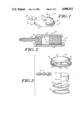
- FIG. 1 is a side elevated view of the preferred embodiment of the invention
- FIG. 2 is a cross-sectional view along lines 2--2 of FIG. 1;
- FIG. 3 is an exploded view of FIG. 1;
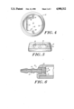
- FIG. 4 is a bottom view of the top element of FIG. 3;
- FIG. 5 is a front view of the top element of FIG. 3;
- FIG. 6 is an enlarged view of the exit port region of FIG. 2;
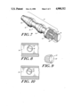
- FIG. 7 is an enlarged cross sectional view of the port outlet connector of FIGS. 2 and 3;
- FIG. 8 is a cross-sectional view along lines 8--8 of FIG. 1;
- FIG. 9 is a side view of the head and neck region of another embodiment of the port outlet connector of the invention.
- FIG. 10 is a cross-sectional view similar to FIG. 8 using the device of FIG. 9;
- the filter system of the invention will be described in connection with a side-entry microinjection port, which port is the subject of a commonly owned patent application of even date and entitled MICRO-INJECTION PORT. The disclosure of that patent application is incorporated herein by reference. It should be understood, however, that the filter system of this invention may be used in virtually any injection port or in other infusion devices, such as for example an infusate pump.
- the side-entry injection port 20 has a housing 24 shaped substantially like a disk.
- the housing 24 is made of a rigid material, such as metal, and defines an internal injection chamber 21 accessible through an opening 26 in the housing 24, which opening 26 is sealed by the septum 22.
- a biocompatible metal is preferred over plastic because a metal housing generally requires thinner walls to achieve the desired rigidity and compression on the septum.
- An implant grade Titanium alloy has been used successfully.
- the housing 24 preferably has flat, parallel disk-shaped top and bottom walls, 28 and 30, respectively, which walls are connected along their periphery by a side wall 32.
- the top and bottom walls 28, 30 are concentric, with the top wall 28 somewhat smaller than the bottom wall 30.
- the side wall 32 slopes gently from the periphery of the top wall 28 to the periphery of the bottom wall 30.
- the device has rounded corners to minimize tissue irritation when implanted.
- the top, bottom and side walls 28, 30, 32 along with chamber-facing surface 34 of the septum 22 together define the injection chamber 21.
- the opening 26 is in the side wall 32 of the housing 24 and is sealed off by the septum 22.
- the opening 26 extends approximately 80° around the circular side wall 32.
- the remainder of the side wall 32 is solid, except for an exit port 36, which exit port provides a filter and an exit path for fluid introduced into the injection chamber 21.
- the exit port 36 communicates with the injection chamber 21 and is located in the side wall 32 opposite the septum 22.
- the exit port 36 in the preferred embodiment is defined by a port outlet connector 38 fitted into a bore 40 in the side wall 32 of the housing 24.
- the port outlet connector 38 may be made of the same biocompatible material as the housing to facilitate the attachment of the port outlet connector 38 to the housing. Other materials, however, may be substituted.
- the port outlet connector 38 and the bore 40 in the side wall 32 together serve as a filter system, an exit port and a catheter attachment site for the side-entry injection port 20.
- the injection port 20 including the filter system of the invention is shown in an exploded view in FIG. 3.
- the rigid housing 24 is constructed from two separate elements, a top element 42 and a bottom element 44.
- the top element 42 defines the top wall 28 and the side wall 32 of the injection port 20.
- a lip 46 extends about the periphery of the side wall 32 to form a seat or step 48 also extending completely about the periphery of the side wall 32.
- the step 48 is parallel to the top wall 28 and is provided to mate in face-to-face relation with the bottom element 44 when the device is assembled.
- the bottom element 44 is sized to fit just within the lip 46.
- the top and bottom elements 42, 44 capture a gasket 50 and the septum 22.
- the gasket 50 is sized to fit within the lip 46 and between the facing surfaces of the bottom element 44 and the step 48.
- the gasket 50 is essentially a silicone rubber ring and is captured between the top and bottom elements to form a leak-proof seal.
- the top element 42 has a hollowed out center 49.
- the hollowed out center has a neck region and a head region.
- the neck region has neck side walls 52 connected at one end by a neck base wall 54.
- the head region defines a shape similar to a semicircle.
- the head region has two shoulder walls 56, one each extending perpendicularly from each of the neck side walls 52, and has an arcuate front wall 58 connecting the free ends of the shoulder walls 56.
- the septum 22 is sized to fit compressively within the head region.
- the septum also is shaped similar to a slice of a disk, having a chamber-facing wall 60 and an arcuate septum front wall 62.
- the septum front wall 62 mates with the arcuate front wall 58 of the head region and the ends of the chamber-facing wall 60 mate with the shoulder walls 56 of the head region.
- the opening 26 in the top element 42 is shown in detail in FIG. 5.
- the opening 26 has a beveled edge 64. It is centered relative to the arcuate front wall 58 and is located directly across from the neck base wall 54.
- the exit port 36 is located and centered in the neck base wall 54.
- top and bottom elements 42, 44 compressively capture the gasket 50 and the septum 22.
- the bottom element 44 is provided with a chamfer (not shown) so that it may be interference fit together with the top element 42.
- the neck side and neck base walls 52, 54 together with the chamber-facing surface 34 of the septum 22 define the side walls of the injection chamber 21.
- the inside surface 66 of the top wall 28 and the inside-facing surface 68 of the bottom element 44 form the top and bottom walls of the injection chamber 21.
- the side-entry injection-port 20 When used in pediatric patients, the side-entry injection-port 20 has a height of about 3/8" (0.375") or less. In the embodiment described, the height is about 0.225".
- the port outlet connector 38 and the bore 40 in the housing 24 define a combination filter system, exit port and catheter attachment site.
- the port outlet connector 38 is a cylindrical shaft having a main body 70, a neck 72 and a head 74.
- the end of the main body 70 meeting neck 72 is a straight cylinder 73 and is sized to fit snugly in the cylindrical bore 40 in the housing 24.
- the remaining portion of the main body 70 extends from the housing 24 and has conventional barbs 76 for attaching a catheter (not shown).
- An axial bore 78 extends centrally through the main body 70 of the port outlet connector 38 from the barbed end to the neck 72.
- the head 74 also is a straight cylinder.
- the neck 72 defines a tapering cylinder, with the larger end meeting the head 74.
- the head 74 and neck 72 have a smaller diameter than that of the cylindrical bore 40 in the housing 24 into which they fit.
- the walls of the cylindrical bore 40 in the housing 24 and the head and neck 72, 74 define an annular space 80 communicating with the injecting chamber 21.
- This annular space 80 also communicates with the axial bore 78 in the main body 70 via a transverse bore 82 through the neck 72.
- fluid injected into the injection chamber 21 flows through the annular space 80, into the transverse bore 82, then into the axial bore 78 and finally into the catheter (not shown).
- the catheter delivers the fluid to the appropriate body location.
- the filter space 84 between the terminal end 86 of the head 74 and the neck base wall 54 of the injection chamber 21 defines the injection port filter.
- the terminal end 86 of the head 74 is positioned flush with the neck base wall 54 of the injection chamber 21.
- the peripheral surface of the terminal end 86 of the connector head 74 may be smooth such that the filter space 84 is an open ring.
- the peripheral surface of the terminal end 86' of the head 74' may be notched so that a ring of holes 88 (FIG. 10) rather than an open ring defines the filter.
- the cross sectional filter area (the area of the ring shown in FIG. 8 or the sum of the area of the individual holes shown in FIG. 10) is greater than the cross sectional area of the exit and delivery path (the smaller of the transverse bore, the axial bore and the catheter inside diameter). Fluid restriction is removed under these conditions. If the cross-sectional filter area is less than the cross-sectional area of the exit and delivery path, then preferably the walls of the head 74 and neck 72 taper quickly from the terminal end 86 of the head 74 to relieve fluid restriction.
- the port outlet connector 38 is welded to the bore 40, the weld having a maximum width 0.050".
- the welded assembly does not leak air when tested at 45 PSI for 5 seconds.
- the filter of the invention is extremely simple to manufacture as only two parts are required. It is particularly useful for the small side-entry injection port because it eliminates many of the difficulties involved with manufacturing, manipulating and attaching a small, separate part. In particular, it eliminates manufacturing and attaching a small filter as a separate element of the injection port. It should be understood, however, that the filter may be used in any injection port regardless of size and further may be useful in devices other than injection ports.
Abstract
Description
Claims (18)
Priority Applications (1)
| Application Number | Priority Date | Filing Date | Title |
|---|---|---|---|
| US07/151,407 US4900312A (en) | 1988-02-02 | 1988-02-02 | Infusion device filter |
Applications Claiming Priority (1)
| Application Number | Priority Date | Filing Date | Title |
|---|---|---|---|
| US07/151,407 US4900312A (en) | 1988-02-02 | 1988-02-02 | Infusion device filter |
Publications (1)
| Publication Number | Publication Date |
|---|---|
| US4900312A true US4900312A (en) | 1990-02-13 |
Family
ID=22538623
Family Applications (1)
| Application Number | Title | Priority Date | Filing Date |
|---|---|---|---|
| US07/151,407 Expired - Lifetime US4900312A (en) | 1988-02-02 | 1988-02-02 | Infusion device filter |
Country Status (1)
| Country | Link |
|---|---|
| US (1) | US4900312A (en) |
Cited By (9)
| Publication number | Priority date | Publication date | Assignee | Title |
|---|---|---|---|---|
| EP0586740A1 (en) * | 1992-09-11 | 1994-03-16 | Siemens-Elema AB | Device for preventing passage of air bubbles |
| US6086555A (en) * | 1997-01-17 | 2000-07-11 | C. R. Bard, Inc. | Dual reservoir vascular access port with two-piece housing and compound septum |
| US20110137335A1 (en) * | 2007-09-07 | 2011-06-09 | Crusader Medical Llc | Percutaneous Retrievable Vascular Filter |
| US8734480B2 (en) | 2011-08-05 | 2014-05-27 | Merit Medical Systems, Inc. | Vascular filter |
| US8740931B2 (en) | 2011-08-05 | 2014-06-03 | Merit Medical Systems, Inc. | Vascular filter |
| US9028525B2 (en) | 2007-09-07 | 2015-05-12 | Merit Medical Systems, Inc. | Percutaneous retrievable vascular filter |
| US9452039B2 (en) | 2012-02-23 | 2016-09-27 | Merit Medical Systems, Inc. | Vascular filter |
| US9731104B2 (en) | 2010-04-23 | 2017-08-15 | Medical Components, Inc. | Implantable dual reservoir access port |
| US10722338B2 (en) | 2013-08-09 | 2020-07-28 | Merit Medical Systems, Inc. | Vascular filter delivery systems and methods |
Citations (12)
| Publication number | Priority date | Publication date | Assignee | Title |
|---|---|---|---|---|
| US3951147A (en) * | 1975-04-07 | 1976-04-20 | Metal Bellows Company | Implantable infusate pump |
| US3958557A (en) * | 1975-03-10 | 1976-05-25 | Texas Medical Products, Inc. | Coronary artery bypass graft testing device and method |
| US4190048A (en) * | 1978-07-14 | 1980-02-26 | Metal Bellows Corporation | Infusate injection apparatus |
| US4266576A (en) * | 1977-11-30 | 1981-05-12 | Eaton Corporation | Flow control device in a protective housing |
| US4464178A (en) * | 1981-11-25 | 1984-08-07 | Dalton Michael J | Method and apparatus for administration of fluids |
| US4484912A (en) * | 1980-06-09 | 1984-11-27 | Bentley Laboratories | Atraumatic blood access device sealing mechanism |
| US4496343A (en) * | 1982-06-14 | 1985-01-29 | Infusaid Corporation | Infusate pump |
| US4511163A (en) * | 1982-07-14 | 1985-04-16 | Mead Johnson & Company | Adaptable tip tubing connector |
| US4547194A (en) * | 1984-03-16 | 1985-10-15 | Moorehead Harvey R | Hub assemblies and extensions for indwelling catheter tubes and method |
| US4692147A (en) * | 1980-04-02 | 1987-09-08 | Medtronic, Inc. | Drug administration device |
| US4762517A (en) * | 1986-09-18 | 1988-08-09 | Healthcare Technologies, Inc. | Subcutaneously-implanted drug delivery system for intravenous injections, and the like |
| US4781681A (en) * | 1987-09-15 | 1988-11-01 | Gv Medical, Inc. | Inflatable tip for laser catheterization |
-
1988
- 1988-02-02 US US07/151,407 patent/US4900312A/en not_active Expired - Lifetime
Patent Citations (12)
| Publication number | Priority date | Publication date | Assignee | Title |
|---|---|---|---|---|
| US3958557A (en) * | 1975-03-10 | 1976-05-25 | Texas Medical Products, Inc. | Coronary artery bypass graft testing device and method |
| US3951147A (en) * | 1975-04-07 | 1976-04-20 | Metal Bellows Company | Implantable infusate pump |
| US4266576A (en) * | 1977-11-30 | 1981-05-12 | Eaton Corporation | Flow control device in a protective housing |
| US4190048A (en) * | 1978-07-14 | 1980-02-26 | Metal Bellows Corporation | Infusate injection apparatus |
| US4692147A (en) * | 1980-04-02 | 1987-09-08 | Medtronic, Inc. | Drug administration device |
| US4484912A (en) * | 1980-06-09 | 1984-11-27 | Bentley Laboratories | Atraumatic blood access device sealing mechanism |
| US4464178A (en) * | 1981-11-25 | 1984-08-07 | Dalton Michael J | Method and apparatus for administration of fluids |
| US4496343A (en) * | 1982-06-14 | 1985-01-29 | Infusaid Corporation | Infusate pump |
| US4511163A (en) * | 1982-07-14 | 1985-04-16 | Mead Johnson & Company | Adaptable tip tubing connector |
| US4547194A (en) * | 1984-03-16 | 1985-10-15 | Moorehead Harvey R | Hub assemblies and extensions for indwelling catheter tubes and method |
| US4762517A (en) * | 1986-09-18 | 1988-08-09 | Healthcare Technologies, Inc. | Subcutaneously-implanted drug delivery system for intravenous injections, and the like |
| US4781681A (en) * | 1987-09-15 | 1988-11-01 | Gv Medical, Inc. | Inflatable tip for laser catheterization |
Cited By (12)
| Publication number | Priority date | Publication date | Assignee | Title |
|---|---|---|---|---|
| EP0586740A1 (en) * | 1992-09-11 | 1994-03-16 | Siemens-Elema AB | Device for preventing passage of air bubbles |
| US5417663A (en) * | 1992-09-11 | 1995-05-23 | Siemens Aktiengesellschaft | Apparatus for conveying liquids |
| US6086555A (en) * | 1997-01-17 | 2000-07-11 | C. R. Bard, Inc. | Dual reservoir vascular access port with two-piece housing and compound septum |
| US20110137335A1 (en) * | 2007-09-07 | 2011-06-09 | Crusader Medical Llc | Percutaneous Retrievable Vascular Filter |
| US8795318B2 (en) | 2007-09-07 | 2014-08-05 | Merit Medical Systems, Inc. | Percutaneous retrievable vascular filter |
| US9028525B2 (en) | 2007-09-07 | 2015-05-12 | Merit Medical Systems, Inc. | Percutaneous retrievable vascular filter |
| US9731104B2 (en) | 2010-04-23 | 2017-08-15 | Medical Components, Inc. | Implantable dual reservoir access port |
| US10485964B2 (en) | 2010-04-23 | 2019-11-26 | Medical Components, Inc. | Implantable dual reservoir access port |
| US8734480B2 (en) | 2011-08-05 | 2014-05-27 | Merit Medical Systems, Inc. | Vascular filter |
| US8740931B2 (en) | 2011-08-05 | 2014-06-03 | Merit Medical Systems, Inc. | Vascular filter |
| US9452039B2 (en) | 2012-02-23 | 2016-09-27 | Merit Medical Systems, Inc. | Vascular filter |
| US10722338B2 (en) | 2013-08-09 | 2020-07-28 | Merit Medical Systems, Inc. | Vascular filter delivery systems and methods |
Similar Documents
| Publication | Publication Date | Title |
|---|---|---|
| US5897528A (en) | Filtered intracerebroventricular or intraspinal access port with direct cerebrospinal fluid access | |
| US4915690A (en) | Micro-injection port | |
| US5137529A (en) | Injection port | |
| US5108377A (en) | Micro-injection port | |
| US5695490A (en) | Implantable treatment material device | |
| US5840063A (en) | Septumless implantable treatment material device | |
| US5306255A (en) | Portcatheter | |
| US6013051A (en) | Filtered access port with filter bypass for accessing body fluid samples | |
| US5336194A (en) | Implantable apparatus | |
| US5718682A (en) | Access port device and method of manufacture | |
| US20180126140A1 (en) | Volume Reducing Reservoir Insert for an Infusion Port | |
| US5387192A (en) | Hybrid portal and method | |
| US5352204A (en) | Implantable access devices | |
| JP3531069B2 (en) | Drug pump and device for limiting access to subcutaneous membrane of subcutaneously implanted device | |
| US20030135168A1 (en) | Implantable device for injecting medical substances | |
| JPH0698193B2 (en) | Implantable vascular connection port and vascular connection device | |
| EP2083908B1 (en) | Vascular access device stagnant fluid displacement | |
| AU2004229486A1 (en) | Implantable vascular access device | |
| US4900312A (en) | Infusion device filter | |
| USH150H (en) | Accessory module for implantable fluid dispensing device | |
| US20120191074A1 (en) | Reduced sized programmable pump | |
| KR102322521B1 (en) | Filtering connector for chemical injection hose | |
| US11745003B2 (en) | Implantable access port with one-directional filter | |
| US20130103006A1 (en) | Mesh protection system | |
| MXPA97009871A (en) | Implement access device |
Legal Events
| Date | Code | Title | Description |
|---|---|---|---|
| AS | Assignment |
Owner name: C. R. BARD, INC., 731 CENTRAL AVENUE, MURRAY HILL, Free format text: ASSIGNMENT OF ASSIGNORS INTEREST.;ASSIGNOR:NADEAU, MICHAEL A.;REEL/FRAME:004879/0781 Effective date: 19880411 Owner name: C. R. BARD, INC., A NEW JERSEY CORP.,NEW JERSEY Free format text: ASSIGNMENT OF ASSIGNORS INTEREST;ASSIGNOR:NADEAU, MICHAEL A.;REEL/FRAME:004879/0781 Effective date: 19880411 |
|
| STCF | Information on status: patent grant |
Free format text: PATENTED CASE |
|
| FEPP | Fee payment procedure |
Free format text: PAYOR NUMBER ASSIGNED (ORIGINAL EVENT CODE: ASPN); ENTITY STATUS OF PATENT OWNER: LARGE ENTITY |
|
| FPAY | Fee payment |
Year of fee payment: 4 |
|
| FPAY | Fee payment |
Year of fee payment: 8 |
|
| FPAY | Fee payment |
Year of fee payment: 12 |