US4900271A - Electrical connector for fuel injector and terminals therefor - Google Patents
Electrical connector for fuel injector and terminals therefor Download PDFInfo
- Publication number
- US4900271A US4900271A US07/314,992 US31499289A US4900271A US 4900271 A US4900271 A US 4900271A US 31499289 A US31499289 A US 31499289A US 4900271 A US4900271 A US 4900271A
- Authority
- US
- United States
- Prior art keywords
- terminal
- locking
- terminals
- insulator housing
- housing
- Prior art date
- Legal status (The legal status is an assumption and is not a legal conclusion. Google has not performed a legal analysis and makes no representation as to the accuracy of the status listed.)
- Expired - Fee Related
Links
Images
Classifications
-
- H—ELECTRICITY
- H01—ELECTRIC ELEMENTS
- H01R—ELECTRICALLY-CONDUCTIVE CONNECTIONS; STRUCTURAL ASSOCIATIONS OF A PLURALITY OF MUTUALLY-INSULATED ELECTRICAL CONNECTING ELEMENTS; COUPLING DEVICES; CURRENT COLLECTORS
- H01R13/00—Details of coupling devices of the kinds covered by groups H01R12/70 or H01R24/00 - H01R33/00
- H01R13/02—Contact members
- H01R13/10—Sockets for co-operation with pins or blades
- H01R13/11—Resilient sockets
- H01R13/113—Resilient sockets co-operating with pins or blades having a rectangular transverse section
-
- H—ELECTRICITY
- H01—ELECTRIC ELEMENTS
- H01R—ELECTRICALLY-CONDUCTIVE CONNECTIONS; STRUCTURAL ASSOCIATIONS OF A PLURALITY OF MUTUALLY-INSULATED ELECTRICAL CONNECTING ELEMENTS; COUPLING DEVICES; CURRENT COLLECTORS
- H01R13/00—Details of coupling devices of the kinds covered by groups H01R12/70 or H01R24/00 - H01R33/00
- H01R13/40—Securing contact members in or to a base or case; Insulating of contact members
- H01R13/42—Securing in a demountable manner
- H01R13/436—Securing a plurality of contact members by one locking piece or operation
- H01R13/4364—Insertion of locking piece from the front
-
- H—ELECTRICITY
- H01—ELECTRIC ELEMENTS
- H01R—ELECTRICALLY-CONDUCTIVE CONNECTIONS; STRUCTURAL ASSOCIATIONS OF A PLURALITY OF MUTUALLY-INSULATED ELECTRICAL CONNECTING ELEMENTS; COUPLING DEVICES; CURRENT COLLECTORS
- H01R13/00—Details of coupling devices of the kinds covered by groups H01R12/70 or H01R24/00 - H01R33/00
- H01R13/40—Securing contact members in or to a base or case; Insulating of contact members
- H01R13/42—Securing in a demountable manner
- H01R13/436—Securing a plurality of contact members by one locking piece or operation
- H01R13/4367—Insertion of locking piece from the rear
- H01R13/4368—Insertion of locking piece from the rear comprising a temporary and a final locking position
-
- H—ELECTRICITY
- H01—ELECTRIC ELEMENTS
- H01R—ELECTRICALLY-CONDUCTIVE CONNECTIONS; STRUCTURAL ASSOCIATIONS OF A PLURALITY OF MUTUALLY-INSULATED ELECTRICAL CONNECTING ELEMENTS; COUPLING DEVICES; CURRENT COLLECTORS
- H01R13/00—Details of coupling devices of the kinds covered by groups H01R12/70 or H01R24/00 - H01R33/00
- H01R13/46—Bases; Cases
- H01R13/52—Dustproof, splashproof, drip-proof, waterproof, or flameproof cases
- H01R13/5219—Sealing means between coupling parts, e.g. interfacial seal
- H01R13/5221—Sealing means between coupling parts, e.g. interfacial seal having cable sealing means
-
- H—ELECTRICITY
- H01—ELECTRIC ELEMENTS
- H01R—ELECTRICALLY-CONDUCTIVE CONNECTIONS; STRUCTURAL ASSOCIATIONS OF A PLURALITY OF MUTUALLY-INSULATED ELECTRICAL CONNECTING ELEMENTS; COUPLING DEVICES; CURRENT COLLECTORS
- H01R13/00—Details of coupling devices of the kinds covered by groups H01R12/70 or H01R24/00 - H01R33/00
- H01R13/40—Securing contact members in or to a base or case; Insulating of contact members
- H01R13/42—Securing in a demountable manner
- H01R13/422—Securing in resilient one-piece base or case, e.g. by friction; One-piece base or case formed with resilient locking means
- H01R13/4223—Securing in resilient one-piece base or case, e.g. by friction; One-piece base or case formed with resilient locking means comprising integral flexible contact retaining fingers
-
- H—ELECTRICITY
- H01—ELECTRIC ELEMENTS
- H01R—ELECTRICALLY-CONDUCTIVE CONNECTIONS; STRUCTURAL ASSOCIATIONS OF A PLURALITY OF MUTUALLY-INSULATED ELECTRICAL CONNECTING ELEMENTS; COUPLING DEVICES; CURRENT COLLECTORS
- H01R13/00—Details of coupling devices of the kinds covered by groups H01R12/70 or H01R24/00 - H01R33/00
- H01R13/46—Bases; Cases
- H01R13/52—Dustproof, splashproof, drip-proof, waterproof, or flameproof cases
- H01R13/5205—Sealing means between cable and housing, e.g. grommet
- H01R13/5208—Sealing means between cable and housing, e.g. grommet having at least two cable receiving openings
-
- H—ELECTRICITY
- H01—ELECTRIC ELEMENTS
- H01R—ELECTRICALLY-CONDUCTIVE CONNECTIONS; STRUCTURAL ASSOCIATIONS OF A PLURALITY OF MUTUALLY-INSULATED ELECTRICAL CONNECTING ELEMENTS; COUPLING DEVICES; CURRENT COLLECTORS
- H01R13/00—Details of coupling devices of the kinds covered by groups H01R12/70 or H01R24/00 - H01R33/00
- H01R13/46—Bases; Cases
- H01R13/533—Bases, cases made for use in extreme conditions, e.g. high temperature, radiation, vibration, corrosive environment, pressure
Definitions
- Electrical components that are mounted in the engine compartment of a vehicle are subjected to wide ranges of environmental conditions and physical abuse.
- electrical components in an engine compartment are subject to substantial ranges in temperature due to climatic changes and engine operating conditions. These components are exposed to soil and are frequently splashed with water, lubricants and fuels.
- Electrical components on a vehicle are almost continuously subjected to vibrations during use, are frequently subjected to sharp jarring movement as the vehicle traverses a rough road, and are often directly contacted by maintenance personnel working in the engine compartment.
- the electrical connectors for electronic fuel injector systems are subjected to all of the above described conditions and constraints.
- the connectors for fuel injectors or the temperature sensors associated with fuel injectors are mounted very close to the engine, and therefore are subjected to particularly broad ranges of temperature variation and vibration.
- Electrical connectors in the vicinity of fuel injectors are particularly susceptible to frequent splashing by water, lubricants or fuel.
- the electrical connectors for fuel injectors and/or their temperature sensors are typically in locations where they will be contacted by maintenance personnel working on the vehicle. The typical inadvertent contact occurs as maintenance personnel forcibly push or pull wires to access an adjacent electrical or mechanical component on the vehicle.
- TPA terminal position assurance
- Yet another object of the subject invention is to provide an electrical connector for fuel injectors and temperature sensors that positively ensures correct assembly of the components thereof.
- Still an additional object of the subject invention is to provide an electrical connector for fuel injectors and temperature sensors where the components thereof can be lockingly retained in an initial preassembled condition and can subsequently be advanced and locked in a fully assembled condition.
- Another object of the subject invention is to provide an electrical connector for fuel injectors and temperature sensors where the wire seals are securely protected from damage during component assembly and during use.
- An additional object of the subject invention is to provide an electrical connector for fuel injectors and temperature sensors where the terminals cannot be misinserted into the housing or damaged by an attempt to misinsert.
- a further object is to provide terminals that consistently provide high normal contact forces in a high vibration environment.
- the subject invention is directed to an electrical connector, a housing assembly for an electrical connector and terminals, all of which may be used with an automotive fuel injector and/or the temperature sensor associated with an automotive fuel injector.
- the fuel injector or temperature sensor will comprise an open-ended housing having electrical terminals securely mounted therein.
- the terminals typically will be spade terminals that are substantially surrounded and protected by the housing of the fuel injector or temperature sensor.
- the connector of the subject invention comprises an insulator housing formed from a nonconductive material.
- the insulator housing may be unitarily molded from a plastic material, and comprises a forward mating end and an opposed rearward wire receiving end. The forward mating end may be constructed for lockingly engaging the housing of the fuel injector or temperature sensor.
- the insulator housing comprises at least one through aperture defining terminal cavities for permitting the insertion of a pair of terminals from the rear of the insulator housing and for enabling subsequent mating of those terminals with spade terminals in the fuel injector or temperature sensor.
- the interior of the insulator housing comprises locking means for lockingly engaging the terminals inserted therein.
- the locking means may comprise deflectable locking levers that lockingly engage the terminals.
- the locking means may require the sequential insertion of the two terminals and may be constructed such that the insertion of the second terminal into the housing is contingent upon full and proper locking engagement of the first terminal therein.
- the connector may further comprise a wire seal for sealing engagement about the wires, and a mating seal for sealing engagement with the housing of the fuel injector or temperature sensor.
- the connector further comprises a terminal position assurance (TPA) component.
- TPA terminal position assurance
- the TPA component is constructed to assure proper positioning of both terminals.
- the TPA component may be lockable to the housing in alternate first and second positions.
- the TPA component may be locked to the housing in a first position for shipment to a final assembly location.
- the TPA component may protect and securely retain the wire seal in the housing.
- the housing may be shipped as part of a subassembly comprising the housing, the forward mating seal, the wire seal and the TPA component.
- the terminals and the wire leads connected thereto may then be inserted through the TPA component for locking engagement of the terminals in the housing.
- the TPA component may be advanced to its fully seated condition for positively assuring the position of the terminals and for urging the wire seal into tighter sealing engagement about the wires.
- the connector may further comprise a rear protective boot which is slidably mounted over the wires and is lockingly mountable to the rearward end of the housing.
- the boot may be lockingly mounted to locking wedges unitarily molded to the insulator housing intermediate the opposed forward and rearward ends thereof.
- the terminals preferably are elastically supported dual cantilever beam spade-receiving terminals which provide four points of contact with each spade terminal with high normal contact forces. Terminals of this general type are described in co-pending patent application Ser. No. 255,001 which was filed on Oct. 6, 1988 and which is assigned to the assignee of the subject invention. The disclosure of the co-pending application Ser. No. 255,001 is incorporated herein by reference.
- the dual cantilever beam spade receiving terminals described herein are particularly advantageous for the subject fuel injector and temperature sensor interconnect in that they provide a small cross-sectional area that readily permits insertion of the terminals from the rearward end of the housing and through appropriate aperture means in both the TPA component and the wire seal.
- the forward mating ends of these terminals may define smaller cross-sectional dimensions than the rearward wire mounting ends of the terminals, thereby ensuring that the forward mating ends of the terminals can be passed through the wire seal without causing damage.
- the terminals may further be constructed to permit alternate 180° insertion positions with multiple locking in the housing.
- the locking interengagement between the housing and the terminals may provide for both a compressive locking component and a tension locking component with correspondingly high pullout forces.
- the lock orientation and the configuration of the terminal cavities will positively prevent full seating of the TPA component unless both terminals are in their proper orientation and are fully seated and locked in the housing.
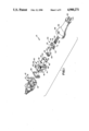
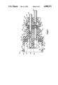
- FIG. 1 is an exploded perspective view of the connector assembly of the subject invention.
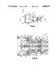
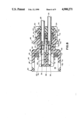
- FIG. 2 is a side elevational view of a subassembly of the subject connector.
- FIG. 3 is a cross-sectional view taken along line 3--3 in FIG. 2.
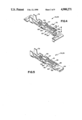
- FIG. 4 is a perspective view of a terminal for incorporation into the connector of the subject invention.
- FIG. 5 is a perspective view of the terminal shown in FIG. 4 with a spade terminal mated thereto.
- FIG. 6 is a side elevational view of the mated terminals shown in FIG. 5.
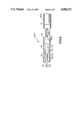
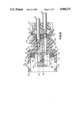
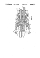
- FIG. 7 is a cross-sectional view similar to FIG. 3 in a later stage of assembly.
- FIG. 8 is a cross-sectional view similar to FIG. 7 showing the connector in a fully assembled condition.
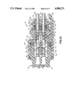
- FIG. 9 is a cross-sectional view similar to FIG. 7 showing an attempt to misassemble the connector.
- FIG. 10 is a cross-sectional view similar to FIG. 8 but showing the connector mated with a fuel injector or temperature sensor.
- FIG. 11 is a cross-sectional view showing the use of a probe to permit selective removal of terminals from their locked position in the housing.
- the connector of the subject invention is identified generally by the numeral 10 in FIG. 1.
- the connector 10 is intended for mounting to an automotive fuel injector or temperature sensor which is identified generally by the numeral 12 in FIG. 1.
- the fuel injector or temperature sensor 12 to which the subject connector 10 is mountable comprises a housing 14 of generally opened rectangular configuration and defining a mating end 16.
- a pair of spade terminals (not shown) are mounted within the rectangular housing 14 and project toward the open mating end 16.
- a pair of locking wedges 18 project from the exterior of the housing 14.
- the electrical connector 10 of the subject invention is lockingly and sealingly engageable with the fuel injector or temperature sensor 12 with high quality electrical connection to the spade terminals therein.
- the connector 10 illustrated in FIG. 1 comprises an insulator housing 20 which is unitarily molded from polyester or other suitable plastic material.
- the insulator housing 20 comprises a mating end 22 and an opposed wire mounting end 24.
- the mating end 22 of the insulator housing 20 defines the portion of the connector 10 that is lockingly engageable with the housing 14 of the fuel injector or temperature sensor 12.
- a mating seal 25 is securely receivable within the housing 20 from the mating end 22 thereof, and provides sealing protection for the electrically conductive components of the connector 10 and the fuel injector or temperature sensor 12.
- a wire seal 26 is receivable within the insulator housing 20 from the rear end 24 thereof and will sealingly engage the wires 28 and 29 extending into the connector 10.
- a terminal position assurance (TPA) wedge 30 is engageable with the rear end 24 of the insulator housing 20 in each of two alternate positions, as explained in greater detail below.
- the mating seal 25 and the wire seal 26 can be inserted into the insulator housing 20, and the TPA wedge 30 can be engaged in a first position on the rear end 24 of the insulator housing 20 to define a subassembly 32 as depicted in FIGS. 2 and 3.
- the subassembly 32 can be assembled by the manufacturer of the connector 10 and shipped as a unit to a customer for subsequent complete assembly and installation onto a fuel injector or temperature sensor.
- the subassembly 32 substantially prevents inventory control problems and provides additional assurance of proper assembly of the connector 10.
- the connector 10 further comprises terminals 34 and 35 which are crimped to the wires 28 and 29 as shown in FIG. 1.
- a boot 36 unitarily formed from an elastomeric material such as Nitrile is engaged over the wires 28 and 29 and is engageable with the rear end 24 of the insulator housing 20 in the fully assembled condition of the connector 10.
- the connector 10 can be assembled by sequentially inserting the terminals 34 and 35 through the TPA wedge 30, through the wire seal 26 and into the insulator housing 20 as explained in detail herein.
- the TPA wedge 30 is urged into its second position relative to the rear end 24 of the insulator housing 20 after the terminals 34 and 35 have been properly seated.
- the insulator housing 20 is of unitary molded construction and of generally rectangular external configuration, with opposed top and bottom 38 and 39 and opposed sides 40 and 41.
- the terms top and bottom are used herein for identification purposes only, and do not imply a required gravitational orientation.
- the mating end 22 of the insulator housing 20 is configured to telescopingly slide over the mating end 16 of the housing 14 on the fuel injector or temperature sensor 12 depicted in FIG. 1.
- Locking apertures 42 are unitarily molded into the insulator housing 20 generally adjacent the mating end 22 thereof for locking engagement with the locking wedges 18 on the housing 14 of the fuel injector or temperature sensor 12.
- the insulator housing 20 further comprises a pair of first TPA locks 44, 45 for lockingly engaging the TPA wedge 30 in a first position.
- the first TPA locks 44, 45 are of generally wedge shape and are dimensioned to lockingly receive deflectable latches on the TPA wedge 30 as explained further below.
- the insulator housing 20 further comprises a pair of second TPA locks 46, 47 for lockingly engaging appropriate structures on the TPA wedge 30 in a second relative position of the TPA wedge 30 on the insulator housing 20.
- the exterior of the insulator housing 20 further comprises a plurality of boot locks 48 intermediate the opposed ends 22 and 24 of the insulator housing 20.
- the boot locks 48 also are of generally wedge shape and are dimensioned to engage appropriate locking structures on the boot 36.
- the interior of the insulator housing 20 is shown most clearly in FIG. 3.
- the interior of the insulator housing 20 comprises a forwardly facing mating shoulder 49 and a rearwardly facing shoulder 50 which is configured to define terminal cavities 52 and 53 having rear entrances of cross section dimension "a" corresponding to the cross section of the terminated wire 28, 29 and terminal 34, 35.
- Forwardly directed deflectable locking levers 54 and 55 are cantilevered from portions of the shoulder 50 adjacent the sides 40 and 41 of the insulator housing 20 and are configured to define a minor width "b" for the terminal cavities 52 and 53.
- the forwardly directed deflectable locking levers 54 and 55 terminate at their deflectable forward ends in locking fingers 56 and 57 respectively which are disposed and dimensioned to extend into terminal cavities 52 and 53 to lockingly engage the terminals 34 and 35 as explained below.
- the rearwardly facing cam surfaces of the locking fingers 56, 57 are acutely aligned to the longitudinal axis of the housing 20. However, the forwardly facing locking surfaces of the locking fingers 56, 57 are approximately orthogonal to the longitudinal axis.
- the interior of the insulator housing 20 further comprises a support 58 intermediate the mating shoulder 49 and the forward mating end 22 and extending between the top and bottom 38 and 39 of the housing 20.
- a pair of rearwardly extending deflectable locking levers 60 and 61 are cantilevered from the support 58.
- the locking levers 60 and 61 extend in slightly spaced generally parallel back-to-back relationship from the support 58 and toward the rear 24 of the insulator housing 20.
- the rearwardmost portions of the rearwardly extending deflectable locking levers 60 and 61 define locking fingers 62 and 63 respectively which extend into the terminal cavities 52 and 53 and are generally in line with the locking fingers 56 and 57 of the levers 54 and 55 respectively.
- the distance "c" between the locking fingers 56 and 62 or 57 and 63 prior to deflection is selected to enable locking engagement of the terminals 34 and 35 as explained herein.
- the rearwardly facing cam surfaces of the locking fingers 62, 63 are acutely aligned to the longitudinal axis of the housing 20, while the forwardly facing locking surfaces are generally orthogonal to the longitudinal axis.
- the subassembly 32 depicted in FIGS. 2 and 3 is initially assembled by inserting the mating seal 25 from the forward mating end 22 of the insulator housing 20.
- the mating seal 25 is dimensioned to seat against the mating shoulder 49 and will be engaged by the mating end 16 of the fuel injector or temperature sensor 12 upon mating as illustrated below.
- the wire seal 26 is insertable into the insulator housing 20 from the rear 24 thereof to seat against the shoulder 50.
- the wire seal 26 is formed from an elastomeric material and includes apertures 64 and 65 extending therethrough in alignment with the terminal cavities 52 and 53.
- the apertures 64 and 65 are dimensioned to permit the passage of at least portions of the terminals 34 and 35 therethrough, but will tightly seal against the wires 28 and 29.
- the wire seal 26 further includes a central aperture 66 for receiving a portion of the TPA component 30.
- the TPA component 30 is of unitary molded plastic construction and comprises a generally rectangular body 67 dimensioned to be slidably inserted into the rearward end 24 of the insulator housing 20.
- a tapered wedge 68 extends centrally from the forward end of the body 67 and is dimensioned to be slidably inserted through the aperture 66 in the wire seal 26. Additionally, the wedge 68 is dimensioned to be inserted intermediate the rearwardly extending deflectable locking levers 60 and 61 in the insulator housing 20.
- the TPA wedge 30 further comprises a pair of apertures 70 and 71 extending through the body 67 and alignable with the apertures 64 and 65 in the wire seal 26. The apertures 70 and 71 are dimensioned to receive at least portions of the terminals 34 and 35 as explained further below.
- Deflectable latches 72 and 73 are cantilevered from opposed sides of the body 67 of the TPA wedge 30 and extend forwardly therefrom.
- the latches 72 and 73 are configured to lockingly engage the first TPA locks 44, 45 on the insulator housing 20 to mount the TPA wedge 30 in a first position relative to the insulator housing 20.
- the body 67 further comprises locking wedges 74, 75 which are disposed to engage the second TPA locks 46, 47 on the insulator housing 20 in a second position of the TPA wedge 30 relative to the insulator housing 20.
- the subassembly 32 comprising the insulator housing 20, the mating seal 25, the wire seal 26 and the TPA wedge 30 are assembled as shown most clearly in FIG. 3.
- the mating seal 25 is inserted into the insulator housing 20 from the front mating end 22 therof to be seated against the mating shoulder 49.
- the wire seal 26 is inserted from the rear 24 of the insulator housing 20 to be seated against the shoulder 50.
- the TPA wedge 30 then is advanced into the rear end 24 of the insulator housing 20 such that the wedge 68 passes through the aperture 66 in the wire seal 26.
- the subassembly 32 as depicted in FIG. 3 protects both the mating seal 25 and the wire seal 26.
- the subassembly 32 substantially avoids inventory control problems and can be shipped from the manufacturer of the component 10 for subsequent final assembly at another location as explained further below.
- the terminals 34, 35 are depicted in greater detail in FIGS. 4,5 and 6.
- a large plurality of terminals 34 and 35 can be stamped and formed from a unitary strip of metal, such as beryllium copper, to define either one or two carrier strips for efficiently delivering the terminals 34, 35 to a terminating press apparatus at which the terminals 34, 35 are crimped to wires 28, 29.
- the terminals 34, 35 comprise a forward mating end 76 and an opposed wire mounting end 78 which is crimpable to the respective wire 28, 29.
- the mating end 76 of the terminals 34, 35 is of generally rectangular cross section and defines orthogonal major and minor cross-sectional dimensions "d” and "e” respectively. The dimensions "d” and "e” are approximately equal or slightly less than the major and minor dimensions of the terminal cavities 52 and 53 in the housing 20 to ensure proper orientation of the terminals 34 and 35 as explained below.
- each terminal 34 or 35 comprises a pair of substantially parallel stamped tuning fork contact structures 80 and 81 which extend from a central rectangular tubular support 82.
- the tuning fork contact structure 80 comprises a pair of deflectable contact beams 84 and 85 which are disposed in spaced generally parallel relationship to one another and extend unitarily from a root 86 which in turn extends from the support 82.
- the tuning fork contact structure 81 similarly comprises a pair of opposed deflectable contact beams 88 and 89 which extend unitarily from a root 90 connected unitarily with the support 82.
- the gap between the contact beams 84 and 85 of the tuning fork contact structure 80 and between the contact beams 88 and 89 on the tuning fork contact structure 81 can be precisely controlled in view of the stamping formation of the tuning fork contact structures 80 and 81 as opposed to forming operations which are employed on many terminal constructions.
- the contact forces to be developed by the contact beams 84, 85, 88 and 89 can be precisely controlled and will remain consistently high even after plural mating cycles. High contact forces are further ensured by the provision of straps 92 and 93. More particularly, the strap 92 connects the free ends of the contact beams 84 and 88 to one another and to the rectangular tubular support 82 from which the tuning fork contact structures 80 and 81 extend.
- the strap 93 similarly connects the mating ends of the contact beams 85 and 89 to the rectangular tubular support 82.
- the strap 93 does not unitarily connect the mating ends of the contact beams 85 and 89 to one another, but rather comprises a longitudinal seam.
- the opposed halves of the strap 93 will function as a single structural support in view of the illustrated formation and in view of tin plating that may be applied to the mating end of the terminal 34, 35.
- the straps 92 and 93 are operative to yield higher normal contact forces by the contact beams 84, 85, 88 and 89, and yield even greater consistency after a large number of mating cycles.
- Other advantages and other possible configurations for the terminals 34, 35 are described in co-pending application Ser. No. 255,001, the disclosure of which has been incorporated herein by reference.
- the terminals 34, 35 are intended for mating with a spade terminal 94 as shown in FIG. 5 having a cross section of approximately 0.032 inch by 0.116 inch.
- the terminals 34, 35 achieve mating forces and normal contact forces substantially equal to the force of a typical fast-on terminal but define a cross section of approximately only one third the size of a typical fast-on for this application.
- the small size achieves several very significant advantages, including lower material costs and smaller overall space requirements. Furthermore, the small size enables efficient insertion of the terminals 34, 35 into the rearward end of the subassembly 32 as explained further below.
- the box shape cross section at the mating end 76 of the terminals 34, 35 defines a more robust construction that will not be damaged during insertion and that will not damage the wire seal 26 as illustrated in FIGS. 1 and 3 above.
- this configuration of the terminals 34, 35 enables the subassembly 32 to be shipped to a location for final assembly without fear that the final assembly of the terminals 34, 35 into the subassembly 32 will damage the wires seals 26 that had previously been incorporated into the subassembly 32.
- the rectangular tubular support portion 82 of the terminals 34, 35 defines a pair of opposed generally rectangular locking apertures 96 and 97 therein.
- the locking apertures enable positive locking engagement of the terminals 34, 35 in the insulator housing 20 and further ensure full seating and proper alignment of the terminals 34, 35 as explained below.
- the locking apertures and 97 are directly opposite one another, thereby enabling 180° reversal of the terminals 34, 35.
- the assembly of the connector 10 is completed by sequentially inserting the terminals 34 and 35 into the subassembly 32 as depicted in FIGS. 7 and 8.
- the terminal 34 which is electrically and mechanically mounted to the wire 28 is inserted through the aperture 70 in the TPA wedge 30 and further through the aperture 64 in the wire seal 26.
- the relatively small dimensions of the mating end 76 of the terminal 34 enable the terminal 34 to be passed through the aperture 64 in the wire seal 26 without damage to either the wire seal 26 or the terminal 34.
- the terminal 34 is aligned such that the major axis of the generally rectangular cross-sectioned terminal 34 is aligned parallel to the major axis of the terminal cavity 52.
- the mating end 76 of the terminal 34 will be urged against the acutely aligned rearwardly facing cam surfaces of the locking fingers 56 and 62 on the locking levers 54 and 60 respectively.
- the camming action developed between the mating end 76 of the terminal 34 and the rearwardly facing cam surfaces of the locking fingers 56 and 62 will cause an outward deflection of the locking levers 54 and 60 respectively.
- the approximate alignment of the terminal 34 enabled by the aperture 70 in the TPA wedge 30 will substantially ensure proper alignment of the terminal 34 with the rearwardly facing cam surfaces on the locking fingers 56 and 62, thereby preventing overstress of the locking levers 54 and 60.
- the protection afforded by the external walls of the insulator housing 20 further prevents overstress of the locking levers 54 and 60.
- the locking fingers 56 and 60 Upon sufficient insertion of the terminal 34 into the terminal cavity 52 of the insulator housing 20, the locking fingers 56 and 60 will align respectively with the locking apertures 96 and 97 of the terminal 34. The locking levers 54 and 60 will then resiliently return to their unbiased condition such that the forwardly facing surfaces of the locking fingers 56 and 62 will securely engage the respective locking apertures 96 and 97 to positively prevent rearward withdrawal of the terminal 34 from the insulating housing 20.
- any rearward force exerted on the wire 28 and the terminal 34 will cause the locking lever 54 to be in compression, while simultaneously causing the locking lever 60 to be in tension.
- the combined compressive and tensile reaction forces result in an extremely high rearward force to effect component failure and/or rearward pullout.
- FIG. 8 depicts the terminals 34 and 35 in their fully inserted and locked orientation.
- the locking fingers 57 and 63 of the locking levers 55 and 61 respectively will initially deflect and then resiliently return to an unbiased condition to engage the locking apertures 96 and 97 in the terminal 35.
- the orientation of the locking levers 60 and 61 prevents insertion of the terminal 35 prior to complete insertion of the terminal 34.
- the terminal 34 is depicted in an orientation prior to full insertion.
- the locking fingers 56 and 62 are not engaged with the locking apertures 96 and 97 of the terminal 34. Consequently, the locking levers 54 and 60 remain in a deflected condition with the locking lever 60 abutting the locking lever 61. An attempt to insert the terminal 35 will be impeded by the inability of the locking lever 61 to deflect out of the terminal cavity 53.
- the TPA wedge 30 is advanced into its second relative position on the insulator housing 20.
- the locking wedges 74 and 75 of the TPA wedge 30 will engage with the second TPA locks 46 and 47 on the insulator housing 20.
- the wedge 68 will be urged intermediate the locking levers 60 and 61. If either terminal 34 or 35 is not fully seated in the insulator housing 20, the locking lever 60 or 61 will be deflected toward the center of the insulator housing 20, generally as shown in FIG.
- the ability of the locking wedges 74 and 75 on the TPA wedge 30 to engage the second TPA locks 46 and 47 respectively provides positive assurance that the terminals 34 and 35 are in their proper seated condition in the insulator housing 20.
- the final assembly step of the connector 10 merely requires the axial advancement of the boot 36 over the rear end 24 of the insulator housing 20 such that the locking apertures 98 on the boot 36 engage the locking wedges 48 on the insulator housing 20.
- the assembled connector 10 is employed by axially moving the connector 10 into engagement with the fuel injector or temperature sensor 12, as shown in FIG. 10.
- the mating end 16 of the housing 14 for the fuel injector or temperature sensor 12 is urged into sealing engagement with the mating seal 25.
- the locking wedges 18 on the housing 14 will cause a small deflection adjacent the mating end 22 of the insulator housing 20, enabling the locking wedges 18 to pass into locking engagement with the locking apertures 42 of the insulator housing 20.
- the initial telescoping engagement of the housing 14 with the insulator housing 20 will guide the spade terminals 94 into mating contact with the terminals 34, 35.
- Each spade terminal 94 will be urged between the contact beams of the pair of tuning fork contact structures 80 and 82 such that one planar side of each spade terminal 94 is contacted by contact beams 84 and 88, while the opposed planar side of each spade terminal 94 will be contacted by the contact beams 85 and 89.
- the stamping of each tuning fork contact structure 80 and 82 enables reliable spacing between the opposed pairs of contact beams 84, 85 and 88, 89, such that high normal contact forces can reliably be developed against the spade terminals 94.
- four points of contact will exist against each spade terminal 94.
- the disassembly can be achieved by urging a probe 100 into the mating end of the connector 10 as shown in FIG. 11.
- the probe 100 includes a tapered leading end and is operative to deflect the locking levers 54 and 60 away from one another and out of engagement with the locking apertures 92 and 93.
- the disassembly sequence would be to first remove the boot 36.
- the TPA wedge 30 would then be removed by appropriately deflecting the extreme rear end 24 of the insulator housing 20.
- the probe 100 With the TPA wedge 30 removed to at least its first relative position on the insulator housing 20, the probe 100 is inserted into the mating end of the connector 10 causing the locking levers 54 and 60 to be deflected and enabling the terminal 34 and wire 28 to be removed rearwardly. The probe 100 could then similarly be employed to disengage the terminal 35.
- a connector assembly for a fuel injector or temperature sensor.
- the connector assembly comprises an insulator housing having a plurality of locking levers deflectably mounted therein for lockingly engaging terminals in the insulator housing.
- a TPA wedge is mountable to the rearward end of the insulator housing in alternate first and second positions. The first position of the TPA wedge enables the insulator housing and the TPA wedge, as well as certain seals, to be shipped as a subassembly for subsequent final assembly. Terminals and the wires to which the terminals are connected are then insertable into the subassembly through the TPA wedge. Sufficient insertion of the terminals into the insulator housing achieves locking engagement between the levers in the housing and the terminals.
- the levers preferably are disposed such that the insertion of the second terminal is predicated upon a full and proper seating of the first terminal.
- the TPA wedge can then be advanced from its first position to its second position relative to the housing for positively assuring proper seating of both terminals therein.
Abstract
Description
Claims (19)
Priority Applications (6)
| Application Number | Priority Date | Filing Date | Title |
|---|---|---|---|
| US07/314,992 US4900271A (en) | 1989-02-24 | 1989-02-24 | Electrical connector for fuel injector and terminals therefor |
| EP90300729A EP0384577B1 (en) | 1989-02-24 | 1990-01-24 | Electrical connector for fuel injector and terminals therefor |
| DE69032353T DE69032353T2 (en) | 1989-02-24 | 1990-01-24 | Electrical connector for fuel injector and connections therefor |
| EP95106715A EP0669678B1 (en) | 1989-02-24 | 1990-01-24 | Electrical connector for fuel injector and terminals therefor |
| DE69024240T DE69024240T2 (en) | 1989-02-24 | 1990-01-24 | Electrical connector for fuel injector and connections therefor |
| JP2039547A JP2622888B2 (en) | 1989-02-24 | 1990-02-20 | Electrical connector |
Applications Claiming Priority (1)
| Application Number | Priority Date | Filing Date | Title |
|---|---|---|---|
| US07/314,992 US4900271A (en) | 1989-02-24 | 1989-02-24 | Electrical connector for fuel injector and terminals therefor |
Publications (1)
| Publication Number | Publication Date |
|---|---|
| US4900271A true US4900271A (en) | 1990-02-13 |
Family
ID=23222393
Family Applications (1)
| Application Number | Title | Priority Date | Filing Date |
|---|---|---|---|
| US07/314,992 Expired - Fee Related US4900271A (en) | 1989-02-24 | 1989-02-24 | Electrical connector for fuel injector and terminals therefor |
Country Status (4)
| Country | Link |
|---|---|
| US (1) | US4900271A (en) |
| EP (2) | EP0669678B1 (en) |
| JP (1) | JP2622888B2 (en) |
| DE (2) | DE69032353T2 (en) |
Cited By (103)
| Publication number | Priority date | Publication date | Assignee | Title |
|---|---|---|---|---|
| US4975082A (en) * | 1988-05-30 | 1990-12-04 | Yazaki Corporation | Double engagement structure for terminal and connector |
| US5017162A (en) * | 1990-04-09 | 1991-05-21 | Molex Incorporated | Electrical connector with terminal alignment and position assurance component |
| US5037336A (en) * | 1989-09-29 | 1991-08-06 | Amp Incorporated | Electrical connector with terminal retention member |
| US5049095A (en) * | 1990-06-04 | 1991-09-17 | Molex Incorporated | Automotive fuse socket and terminals therefor |
| US5071374A (en) * | 1990-09-24 | 1991-12-10 | Molex Incorporated | Floatable electrical connector with terminal position assurance component |
| US5088938A (en) * | 1989-05-29 | 1992-02-18 | Yazaki Corporation | Terminal locking block for electrical connectors |
| US5116236A (en) * | 1990-11-05 | 1992-05-26 | Molex Incorporated | Electrical connector with terminal position assurance component |
| US5120234A (en) * | 1991-02-20 | 1992-06-09 | Omega Special Products, Inc. | Electrical connector |
| US5306182A (en) * | 1992-03-02 | 1994-04-26 | Molex Incorporated | Electric connector terminal |
| EP0677890A1 (en) * | 1994-04-07 | 1995-10-18 | The Whitaker Corporation | Electrical terminal back-up spring with anti-chattering support members |
| US5490802A (en) * | 1994-02-24 | 1996-02-13 | United Technologies Automotive, Inc. | Secondary terminal lock plug through stuffer |
| US5494453A (en) * | 1993-09-16 | 1996-02-27 | Yazaki Corporation | Connector housing |
| US5520553A (en) * | 1994-12-08 | 1996-05-28 | Molex Incorporated | Connector with a front end mounted terminal position assurance system |
| EP0732773A2 (en) * | 1990-11-05 | 1996-09-18 | Molex Incorporated | Electrical connector with terminal position assurance component |
| US5562477A (en) * | 1994-11-02 | 1996-10-08 | Caterpillar Inc. | High vibration electrical connector |
| US5620345A (en) * | 1994-10-21 | 1997-04-15 | Macioce; Lawrence | High density pin and socket electrical connector |
| US5755599A (en) * | 1994-03-17 | 1998-05-26 | The Whitaker Corporation | Electrical contact |
| US5803759A (en) * | 1996-07-26 | 1998-09-08 | Chrysler Corp | Two way electrical connector |
| EP0866527A2 (en) * | 1997-03-18 | 1998-09-23 | Framatome Connectors International S.A. | Method of producing an electric connector, and semifinished part produced thereby |
| US5975964A (en) * | 1996-07-25 | 1999-11-02 | Sumitomo Wiring Systems, Ltd. | Female terminal fitting |
| US6099361A (en) * | 1997-05-09 | 2000-08-08 | Sumitomo Wiring Systems, Ltd. | Connector for a printed circuit board or an electric or electronic device |
| US20020034889A1 (en) * | 1998-04-17 | 2002-03-21 | Clark Stephen L. | Power connector |
| US6609932B2 (en) | 2001-05-18 | 2003-08-26 | Sumitomo Wiring Systems, Ltd. | Watertight connector and a method for mounting it |
| US6681458B2 (en) * | 2001-08-02 | 2004-01-27 | International Engine Intellectual Property Company, Llc | Spring clip |
| US6692301B2 (en) | 2001-11-05 | 2004-02-17 | Sumitomo Wiring Systems, Ltd. | Connector |
| US6780027B2 (en) | 2003-01-28 | 2004-08-24 | Fci Americas Technology, Inc. | Power connector with vertical male AC power contacts |
| US20040235357A1 (en) * | 2003-05-23 | 2004-11-25 | Allison Jeffrey W. | Multi-interface power contact and electrical connector including same |
| US20040248449A1 (en) * | 2003-06-06 | 2004-12-09 | Martin Galen Monroe | Sealed electrical connector |
| US6848953B2 (en) | 1998-04-17 | 2005-02-01 | Fci Americas Technology, Inc. | Power connector |
| US20050227514A1 (en) * | 2003-01-28 | 2005-10-13 | Allison Jeffrey W | Power connector with safety feature |
| US20060057897A1 (en) * | 2004-09-14 | 2006-03-16 | Fci Americas Technology, Inc. | Ball grid array connector |
| US20060141818A1 (en) * | 2004-12-23 | 2006-06-29 | Ngo Hung V | Ball grid array contacts with spring action |
| US20060166536A1 (en) * | 1998-04-17 | 2006-07-27 | Northey William A | Electrical power connector |
| US20060172570A1 (en) * | 2005-01-31 | 2006-08-03 | Minich Steven E | Surface-mount connector |
| US20060223362A1 (en) * | 2005-04-05 | 2006-10-05 | Swain Wilfred J | Electrical connector with cooling features |
| US20060228948A1 (en) * | 2004-12-22 | 2006-10-12 | Swain Wilfred J | Electrical power connector |
| US20060228927A1 (en) * | 2003-12-31 | 2006-10-12 | Fci Americas Technology | Electrical power contacts and connectors comprising same |
| US20060228912A1 (en) * | 2005-04-07 | 2006-10-12 | Fci Americas Technology, Inc. | Orthogonal backplane connector |
| US20070147584A1 (en) * | 2005-12-27 | 2007-06-28 | Hofman Gertjan J | Measurement of ash composition using scanning high voltage X-ray sensor |
| US20070197063A1 (en) * | 2006-02-21 | 2007-08-23 | Ngo Hung V | Electrical connectors having power contacts with alignment and/or restraining features |
| US20070205774A1 (en) * | 2006-03-03 | 2007-09-06 | Fci Americas Technology, Inc.. | Electrical connectors |
| US20070207632A1 (en) * | 2006-03-03 | 2007-09-06 | Fci Americas Technology, Inc. | Midplane with offset connectors |
| US20070207641A1 (en) * | 2006-03-03 | 2007-09-06 | Fci Americas Technology, Inc. | High-density orthogonal connector |
| US20070207675A1 (en) * | 2006-03-03 | 2007-09-06 | Fci Americas Technology, Inc. | Edge and broadside coupled connector |
| US20070207674A1 (en) * | 2006-03-03 | 2007-09-06 | Fci Americas Technology, Inc. | Broadside-to-edge-coupling connector system |
| US20070218777A1 (en) * | 2004-04-19 | 2007-09-20 | Claude Casses | Electric Contact and the Part of an Electric Connector Comprising Said Contact |
| US20070275586A1 (en) * | 2006-05-26 | 2007-11-29 | Ngo Hung V | Connectors and contacts for transmitting electrical power |
| US20070293084A1 (en) * | 2006-06-15 | 2007-12-20 | Hung Viet Ngo | Electrical connectors with air-circulation features |
| US20080045079A1 (en) * | 2006-08-21 | 2008-02-21 | Minich Steven E | Electrical Connector System With Jogged Contact Tails |
| US7422444B1 (en) | 2007-02-28 | 2008-09-09 | Fci Americas Technology, Inc. | Orthogonal header |
| US20080248680A1 (en) * | 2007-04-04 | 2008-10-09 | Fci Americas Technology, Inc. | Power cable connector |
| US20080293267A1 (en) * | 2007-05-21 | 2008-11-27 | Fci | Electrical connector with stress-distribution features |
| US7497735B2 (en) | 2004-09-29 | 2009-03-03 | Fci Americas Technology, Inc. | High speed connectors that minimize signal skew and crosstalk |
| US7497736B2 (en) | 2006-12-19 | 2009-03-03 | Fci Americas Technology, Inc. | Shieldless, high-speed, low-cross-talk electrical connector |
| US20090221165A1 (en) * | 2008-02-29 | 2009-09-03 | Buck Jonathan E | Cross talk reduction for high speed electrical connectors |
| USD608293S1 (en) | 2009-01-16 | 2010-01-19 | Fci Americas Technology, Inc. | Vertical electrical connector |
| US20100029126A1 (en) * | 2008-07-29 | 2010-02-04 | Hung Viet Ngo | Electrical communication system having latching and strain relief features |
| USD610548S1 (en) | 2009-01-16 | 2010-02-23 | Fci Americas Technology, Inc. | Right-angle electrical connector |
| USD618180S1 (en) | 2009-04-03 | 2010-06-22 | Fci Americas Technology, Inc. | Asymmetrical electrical connector |
| USD618181S1 (en) | 2009-04-03 | 2010-06-22 | Fci Americas Technology, Inc. | Asymmetrical electrical connector |
| USD619099S1 (en) | 2009-01-30 | 2010-07-06 | Fci Americas Technology, Inc. | Electrical connector |
| US7762857B2 (en) | 2007-10-01 | 2010-07-27 | Fci Americas Technology, Inc. | Power connectors with contact-retention features |
| US20100197166A1 (en) * | 2009-01-30 | 2010-08-05 | Hung Viet Ngo | Electrical connector having power contacts |
| US20100273354A1 (en) * | 2007-07-13 | 2010-10-28 | Stoner Stuart C | Electrical connector system having a continuous ground at the mating interface thereof |
| US20110097934A1 (en) * | 2009-10-28 | 2011-04-28 | Minich Steven E | Electrical connector having ground plates and ground coupling bar |
| US20110117781A1 (en) * | 2009-11-13 | 2011-05-19 | Stoner Stuart C | Attachment system for electrical connector |
| USD640637S1 (en) | 2009-01-16 | 2011-06-28 | Fci Americas Technology Llc | Vertical electrical connector |
| USD641709S1 (en) | 2009-01-16 | 2011-07-19 | Fci Americas Technology Llc | Vertical electrical connector |
| US8043131B2 (en) | 2008-09-19 | 2011-10-25 | Fci Americas Technology Llc | Electrical cable contact |
| US20120088391A1 (en) * | 2010-10-08 | 2012-04-12 | Sumitomo Wiring Systems, Ltd. | Connector |
| USD664096S1 (en) | 2009-01-16 | 2012-07-24 | Fci Americas Technology Llc | Vertical electrical connector |
| USD669437S1 (en) | 2011-01-06 | 2012-10-23 | Wilson Jr Robert M | Insulator |
| DE10320541B4 (en) * | 2002-05-07 | 2012-11-29 | Lear Corp. | Electrical contact element |
| WO2013036318A1 (en) * | 2011-09-08 | 2013-03-14 | International Engine Intellectual Property Company, Llc | Fuel injector solenoid and terminal assembly |
| US8540525B2 (en) | 2008-12-12 | 2013-09-24 | Molex Incorporated | Resonance modifying connector |
| US8545240B2 (en) | 2008-11-14 | 2013-10-01 | Molex Incorporated | Connector with terminals forming differential pairs |
| US20130344736A1 (en) * | 2012-06-14 | 2013-12-26 | Magna Electronics Inc. | Electrical connector with sealed pins |
| USD718253S1 (en) | 2012-04-13 | 2014-11-25 | Fci Americas Technology Llc | Electrical cable connector |
| US8905651B2 (en) | 2012-01-31 | 2014-12-09 | Fci | Dismountable optical coupling device |
| USD720698S1 (en) | 2013-03-15 | 2015-01-06 | Fci Americas Technology Llc | Electrical cable connector |
| US8944831B2 (en) | 2012-04-13 | 2015-02-03 | Fci Americas Technology Llc | Electrical connector having ribbed ground plate with engagement members |
| USD727268S1 (en) | 2012-04-13 | 2015-04-21 | Fci Americas Technology Llc | Vertical electrical connector |
| USD727852S1 (en) | 2012-04-13 | 2015-04-28 | Fci Americas Technology Llc | Ground shield for a right angle electrical connector |
| WO2015044067A3 (en) * | 2013-09-24 | 2015-05-21 | Phoenix Contact Gmbh & Co. Kg | Device for feeding lines through a separating element in a sealed manner |
| US9048583B2 (en) | 2009-03-19 | 2015-06-02 | Fci Americas Technology Llc | Electrical connector having ribbed ground plate |
| USD733662S1 (en) | 2013-01-25 | 2015-07-07 | Fci Americas Technology Llc | Connector housing for electrical connector |
| USD746236S1 (en) | 2012-07-11 | 2015-12-29 | Fci Americas Technology Llc | Electrical connector housing |
| WO2016009129A1 (en) * | 2014-07-16 | 2016-01-21 | Valeo Systemes De Controle Moteur | Electrical connector and electrical connection system |
| US9257778B2 (en) | 2012-04-13 | 2016-02-09 | Fci Americas Technology | High speed electrical connector |
| US9277649B2 (en) | 2009-02-26 | 2016-03-01 | Fci Americas Technology Llc | Cross talk reduction for high-speed electrical connectors |
| EP2765920B1 (en) * | 2011-10-14 | 2016-09-14 | Alcon Research, Ltd. | Collar connector |
| US20170005434A1 (en) * | 2014-01-31 | 2017-01-05 | Panasonic Intellectual Property Management Co., Ltd. | Connector and connector device |
| US9543703B2 (en) | 2012-07-11 | 2017-01-10 | Fci Americas Technology Llc | Electrical connector with reduced stack height |
| US9972932B2 (en) | 2013-08-19 | 2018-05-15 | Fci Americas Technology Llc | Electrical connector with high retention force |
| CN109196726A (en) * | 2016-06-02 | 2019-01-11 | 泰连德国有限公司 | Contact elements and contact system |
| US10230178B2 (en) | 2013-06-07 | 2019-03-12 | Amphenol Fci Asia Pte Ltd | Cable connector |
| US10230189B2 (en) | 2013-12-03 | 2019-03-12 | Amphenol Fci Asia Pte Ltd | Connector and pin receiving contact for such a connector |
| RU189026U1 (en) * | 2019-02-19 | 2019-05-07 | Общество с ограниченной ответственностью "Научно-производственное предприятие "Элтерм-С" | Cable plug |
| US11228130B2 (en) | 2018-03-16 | 2022-01-18 | Fci Usa Llc | High density electrical connectors |
| US11264754B2 (en) * | 2017-03-01 | 2022-03-01 | Molex, Llc | Electrical terminal and connector assembly |
| US20220069518A1 (en) * | 2020-09-03 | 2022-03-03 | Te Connectivity Germany Gmbh | Angled Connector and Method of Assembling an Angled Connector |
| US11394153B2 (en) * | 2019-08-08 | 2022-07-19 | Molex, Llc | Connector and terminal |
| EP4311037A1 (en) * | 2022-07-21 | 2024-01-24 | Aptiv Technologies Limited | Connector assembly with terminal position assurance and blocking feature |
Families Citing this family (16)
| Publication number | Priority date | Publication date | Assignee | Title |
|---|---|---|---|---|
| US5186662A (en) * | 1990-05-30 | 1993-02-16 | Amp Incorporated | Double locking-type electrical connector |
| JPH0434875A (en) * | 1990-05-30 | 1992-02-05 | Amp Japan Ltd | Double lock type electrical connector |
| AU2844692A (en) * | 1992-11-17 | 1994-06-02 | Gem Machinery Industry Company Limited | A three-pole plug |
| JP2813620B2 (en) * | 1993-08-06 | 1998-10-22 | 矢崎総業株式会社 | Waterproof connector |
| JP2573399Y2 (en) * | 1993-10-05 | 1998-05-28 | 矢崎総業株式会社 | Super multi-pole connector |
| US5385491A (en) * | 1993-12-21 | 1995-01-31 | Molex Incorporated | Electrical connector with flexible terminal latch means and terminal position assurance device |
| BR9503164A (en) * | 1994-12-22 | 1997-05-27 | Kostal Leopold Gmbh & Co Kg | Electrical connector with ring joint |
| DE69622369T2 (en) * | 1996-03-11 | 2003-03-27 | Molex Inc | Electrical socket for pen with high contact force |
| FR2749443B1 (en) * | 1996-06-03 | 1998-08-21 | Framatome Connectors Int | FEMALE ELECTRIC CONTACT TERMINAL WITH REINFORCED TRANSITION AREA |
| DE19713960B4 (en) * | 1997-04-04 | 2008-01-24 | The Whitaker Corp., Wilmington | Electrical connection terminal |
| DE19918326A1 (en) * | 1999-04-22 | 2000-10-26 | Delphi Tech Inc | Electrical connection socket |
| DE19944280C1 (en) * | 1999-09-15 | 2001-02-01 | Framatome Connectors Int | Electric plug pin socket contact has insertion guides provided on same side as spring contact arms each divided into 2 parts by elongate slit |
| DK1674407T3 (en) * | 2004-12-22 | 2014-09-22 | Nestec Sa | Food container and method of heating this container |
| WO2008122844A1 (en) * | 2007-04-06 | 2008-10-16 | Fci | Electrical connector and method of manufacture |
| JP6491963B2 (en) * | 2015-06-19 | 2019-03-27 | 矢崎総業株式会社 | connector |
| DE102019113494A1 (en) * | 2019-05-21 | 2020-11-26 | Harting Electric Gmbh & Co. Kg | Contact carrier |
Citations (4)
| Publication number | Priority date | Publication date | Assignee | Title |
|---|---|---|---|---|
| US2419018A (en) * | 1942-01-03 | 1947-04-15 | Pauline E Wood | Connector |
| US4711508A (en) * | 1984-12-14 | 1987-12-08 | Yazaki Corporation | Terminal retaining structure for connector |
| US4776813A (en) * | 1987-12-08 | 1988-10-11 | Molex Incorporated | Sealed connector assembly |
| US4826452A (en) * | 1987-10-16 | 1989-05-02 | Altair International, Inc. | Two-part electrical connector |
Family Cites Families (17)
| Publication number | Priority date | Publication date | Assignee | Title |
|---|---|---|---|---|
| NL134805C (en) * | 1965-11-09 | |||
| GB1487571A (en) * | 1974-01-26 | 1977-10-05 | Amp Inc | Electrical contact |
| DE2458281A1 (en) * | 1974-12-10 | 1976-06-16 | Daut & Rietz Kg | Plug strip fitted with forked springs - has fork contact system which engages with U-shaped soldering stags with outer arms which lock together |
| JPS5972677U (en) * | 1982-11-09 | 1984-05-17 | 矢崎総業株式会社 | connector housing |
| US4544220A (en) * | 1983-12-28 | 1985-10-01 | Amp Incorporated | Connector having means for positively seating contacts |
| US4557542A (en) * | 1984-06-11 | 1985-12-10 | Amp Incorporated | Connector with means for retaining terminals and verifying seating |
| JPS6126272U (en) * | 1984-07-24 | 1986-02-17 | カルソニックカンセイ株式会社 | electrical connectors |
| DE3518067A1 (en) * | 1985-05-20 | 1986-11-20 | Siemens Ag | Contact spring |
| US4708662A (en) * | 1986-06-20 | 1987-11-24 | Amp Incorporated | Connector assembly with pre-staged terminal retainer |
| JPH0314785Y2 (en) * | 1986-08-08 | 1991-04-02 | ||
| JPH0244463Y2 (en) * | 1986-10-02 | 1990-11-26 | ||
| JPH0321016Y2 (en) * | 1986-11-17 | 1991-05-08 | ||
| JPH0321014Y2 (en) * | 1986-12-12 | 1991-05-08 | ||
| KR970000553B1 (en) * | 1987-02-03 | 1997-01-13 | 후르가와 덴끼 고오교오 가부시기가이샤 | Electrical connector device with a number of terminals |
| JPS63257187A (en) * | 1987-04-14 | 1988-10-25 | 矢崎総業株式会社 | Moisture-proof connector |
| JPH07101621B2 (en) * | 1987-06-16 | 1995-11-01 | 住友電装株式会社 | connector |
| US4772234A (en) * | 1987-07-29 | 1988-09-20 | Amp Incorporated | Terminal for establishing electrical contact with a post |
-
1989
- 1989-02-24 US US07/314,992 patent/US4900271A/en not_active Expired - Fee Related
-
1990
- 1990-01-24 EP EP95106715A patent/EP0669678B1/en not_active Expired - Lifetime
- 1990-01-24 DE DE69032353T patent/DE69032353T2/en not_active Expired - Fee Related
- 1990-01-24 DE DE69024240T patent/DE69024240T2/en not_active Expired - Fee Related
- 1990-01-24 EP EP90300729A patent/EP0384577B1/en not_active Expired - Lifetime
- 1990-02-20 JP JP2039547A patent/JP2622888B2/en not_active Expired - Fee Related
Patent Citations (4)
| Publication number | Priority date | Publication date | Assignee | Title |
|---|---|---|---|---|
| US2419018A (en) * | 1942-01-03 | 1947-04-15 | Pauline E Wood | Connector |
| US4711508A (en) * | 1984-12-14 | 1987-12-08 | Yazaki Corporation | Terminal retaining structure for connector |
| US4826452A (en) * | 1987-10-16 | 1989-05-02 | Altair International, Inc. | Two-part electrical connector |
| US4776813A (en) * | 1987-12-08 | 1988-10-11 | Molex Incorporated | Sealed connector assembly |
Cited By (209)
| Publication number | Priority date | Publication date | Assignee | Title |
|---|---|---|---|---|
| US4975082A (en) * | 1988-05-30 | 1990-12-04 | Yazaki Corporation | Double engagement structure for terminal and connector |
| US5088938A (en) * | 1989-05-29 | 1992-02-18 | Yazaki Corporation | Terminal locking block for electrical connectors |
| US5037336A (en) * | 1989-09-29 | 1991-08-06 | Amp Incorporated | Electrical connector with terminal retention member |
| US5017162A (en) * | 1990-04-09 | 1991-05-21 | Molex Incorporated | Electrical connector with terminal alignment and position assurance component |
| US5049095A (en) * | 1990-06-04 | 1991-09-17 | Molex Incorporated | Automotive fuse socket and terminals therefor |
| US5071374A (en) * | 1990-09-24 | 1991-12-10 | Molex Incorporated | Floatable electrical connector with terminal position assurance component |
| EP0732773A3 (en) * | 1990-11-05 | 1998-04-01 | Molex Incorporated | Electrical connector with terminal position assurance component |
| EP0732773A2 (en) * | 1990-11-05 | 1996-09-18 | Molex Incorporated | Electrical connector with terminal position assurance component |
| US5116236A (en) * | 1990-11-05 | 1992-05-26 | Molex Incorporated | Electrical connector with terminal position assurance component |
| US5288243A (en) * | 1991-02-20 | 1994-02-22 | Omega Special Products, Inc. | Electrical Connector |
| US5120234A (en) * | 1991-02-20 | 1992-06-09 | Omega Special Products, Inc. | Electrical connector |
| US5306182A (en) * | 1992-03-02 | 1994-04-26 | Molex Incorporated | Electric connector terminal |
| US5494453A (en) * | 1993-09-16 | 1996-02-27 | Yazaki Corporation | Connector housing |
| US5490802A (en) * | 1994-02-24 | 1996-02-13 | United Technologies Automotive, Inc. | Secondary terminal lock plug through stuffer |
| US5755599A (en) * | 1994-03-17 | 1998-05-26 | The Whitaker Corporation | Electrical contact |
| US5624283A (en) * | 1994-04-07 | 1997-04-29 | The Whitaker Corporation | Electrical terminal back-up spring with anti-chattering support members |
| EP0677890A1 (en) * | 1994-04-07 | 1995-10-18 | The Whitaker Corporation | Electrical terminal back-up spring with anti-chattering support members |
| US5620345A (en) * | 1994-10-21 | 1997-04-15 | Macioce; Lawrence | High density pin and socket electrical connector |
| US5562477A (en) * | 1994-11-02 | 1996-10-08 | Caterpillar Inc. | High vibration electrical connector |
| US5520553A (en) * | 1994-12-08 | 1996-05-28 | Molex Incorporated | Connector with a front end mounted terminal position assurance system |
| US5975964A (en) * | 1996-07-25 | 1999-11-02 | Sumitomo Wiring Systems, Ltd. | Female terminal fitting |
| US5803759A (en) * | 1996-07-26 | 1998-09-08 | Chrysler Corp | Two way electrical connector |
| EP0866527A2 (en) * | 1997-03-18 | 1998-09-23 | Framatome Connectors International S.A. | Method of producing an electric connector, and semifinished part produced thereby |
| EP0866527A3 (en) * | 1997-03-18 | 1999-04-21 | Framatome Connectors International S.A. | Method of producing an electric connector, and semifinished part produced thereby |
| US6099361A (en) * | 1997-05-09 | 2000-08-08 | Sumitomo Wiring Systems, Ltd. | Connector for a printed circuit board or an electric or electronic device |
| US20050118846A1 (en) * | 1998-04-17 | 2005-06-02 | Berg Technologies, Inc. | Power connector |
| US8096814B2 (en) | 1998-04-17 | 2012-01-17 | Fci Americas Technology Llc | Power connector |
| US7374436B2 (en) | 1998-04-17 | 2008-05-20 | Fci Americas Technology, Inc. | Power connector |
| US7309242B2 (en) | 1998-04-17 | 2007-12-18 | Fci Americas Technology, Inc. | Power connector |
| US20080182439A1 (en) * | 1998-04-17 | 2008-07-31 | Fci Americas Technology, Inc. | Power connector |
| US20080214027A1 (en) * | 1998-04-17 | 2008-09-04 | Schell Mark S | Power connector |
| US7488222B2 (en) | 1998-04-17 | 2009-02-10 | Fci Americas Technology, Inc. | Power connector |
| US6848953B2 (en) | 1998-04-17 | 2005-02-01 | Fci Americas Technology, Inc. | Power connector |
| US20020034889A1 (en) * | 1998-04-17 | 2002-03-21 | Clark Stephen L. | Power connector |
| US6869294B2 (en) | 1998-04-17 | 2005-03-22 | Fci Americas Technology, Inc. | Power connector |
| US7314377B2 (en) | 1998-04-17 | 2008-01-01 | Fci Americas Technology, Inc. | Electrical power connector |
| US20050136713A1 (en) * | 1998-04-17 | 2005-06-23 | Schell Mark S. | Power connector |
| US20060194481A1 (en) * | 1998-04-17 | 2006-08-31 | Fci Americas Technology, Inc. | Power connector |
| US20060166536A1 (en) * | 1998-04-17 | 2006-07-27 | Northey William A | Electrical power connector |
| US7070464B2 (en) | 1998-04-17 | 2006-07-04 | Fci Americas Technology, Inc. | Power connector |
| US7059919B2 (en) | 1998-04-17 | 2006-06-13 | Fci Americas Technology, Inc | Power connector |
| US6609932B2 (en) | 2001-05-18 | 2003-08-26 | Sumitomo Wiring Systems, Ltd. | Watertight connector and a method for mounting it |
| US6681458B2 (en) * | 2001-08-02 | 2004-01-27 | International Engine Intellectual Property Company, Llc | Spring clip |
| US6692301B2 (en) | 2001-11-05 | 2004-02-17 | Sumitomo Wiring Systems, Ltd. | Connector |
| DE10320541B4 (en) * | 2002-05-07 | 2012-11-29 | Lear Corp. | Electrical contact element |
| US7140925B2 (en) | 2003-01-28 | 2006-11-28 | Fci Americas Technology, Inc. | Power connector with safety feature |
| US20060063435A1 (en) * | 2003-01-28 | 2006-03-23 | Evans Robert F | Power connector with safety feature |
| US20050227514A1 (en) * | 2003-01-28 | 2005-10-13 | Allison Jeffrey W | Power connector with safety feature |
| US6780027B2 (en) | 2003-01-28 | 2004-08-24 | Fci Americas Technology, Inc. | Power connector with vertical male AC power contacts |
| USRE41283E1 (en) | 2003-01-28 | 2010-04-27 | Fci Americas Technology, Inc. | Power connector with safety feature |
| US7037142B2 (en) | 2003-01-28 | 2006-05-02 | Fci Americas Technology, Inc. | Power connector with safety feature |
| US6848950B2 (en) | 2003-05-23 | 2005-02-01 | Fci Americas Technology, Inc. | Multi-interface power contact and electrical connector including same |
| US20040235357A1 (en) * | 2003-05-23 | 2004-11-25 | Allison Jeffrey W. | Multi-interface power contact and electrical connector including same |
| US20040248449A1 (en) * | 2003-06-06 | 2004-12-09 | Martin Galen Monroe | Sealed electrical connector |
| US7077701B2 (en) * | 2003-06-06 | 2006-07-18 | Tyco Electronics Corporation | Sealed electrical connector |
| US7452249B2 (en) | 2003-12-31 | 2008-11-18 | Fci Americas Technology, Inc. | Electrical power contacts and connectors comprising same |
| US20100048056A1 (en) * | 2003-12-31 | 2010-02-25 | Fci Americas Technology, Inc. | Electrical Power Contacts and Connectors Comprising Same |
| US20070202748A1 (en) * | 2003-12-31 | 2007-08-30 | Fci Americas Technology, Inc. | Electrical power contacts and connectors comprising same |
| US20090042417A1 (en) * | 2003-12-31 | 2009-02-12 | Hung Viet Ngo | Electrical connectors having power contacts with alignment/or restraining features |
| US7690937B2 (en) | 2003-12-31 | 2010-04-06 | Fci Americas Technology, Inc. | Electrical power contacts and connectors comprising same |
| US7775822B2 (en) | 2003-12-31 | 2010-08-17 | Fci Americas Technology, Inc. | Electrical connectors having power contacts with alignment/or restraining features |
| US20080248670A1 (en) * | 2003-12-31 | 2008-10-09 | Fci Americas Technology, Inc. | Electrical power contacts and connectors comprising same |
| US7862359B2 (en) | 2003-12-31 | 2011-01-04 | Fci Americas Technology Llc | Electrical power contacts and connectors comprising same |
| US8062046B2 (en) | 2003-12-31 | 2011-11-22 | Fci Americas Technology Llc | Electrical power contacts and connectors comprising same |
| US7402064B2 (en) | 2003-12-31 | 2008-07-22 | Fci Americas Technology, Inc. | Electrical power contacts and connectors comprising same |
| US20060228927A1 (en) * | 2003-12-31 | 2006-10-12 | Fci Americas Technology | Electrical power contacts and connectors comprising same |
| US8187017B2 (en) | 2003-12-31 | 2012-05-29 | Fci Americas Technology Llc | Electrical power contacts and connectors comprising same |
| US20070218777A1 (en) * | 2004-04-19 | 2007-09-20 | Claude Casses | Electric Contact and the Part of an Electric Connector Comprising Said Contact |
| US7214104B2 (en) | 2004-09-14 | 2007-05-08 | Fci Americas Technology, Inc. | Ball grid array connector |
| US20060057897A1 (en) * | 2004-09-14 | 2006-03-16 | Fci Americas Technology, Inc. | Ball grid array connector |
| US7497735B2 (en) | 2004-09-29 | 2009-03-03 | Fci Americas Technology, Inc. | High speed connectors that minimize signal skew and crosstalk |
| US7476108B2 (en) | 2004-12-22 | 2009-01-13 | Fci Americas Technology, Inc. | Electrical power connectors with cooling features |
| US20060228948A1 (en) * | 2004-12-22 | 2006-10-12 | Swain Wilfred J | Electrical power connector |
| US7226296B2 (en) | 2004-12-23 | 2007-06-05 | Fci Americas Technology, Inc. | Ball grid array contacts with spring action |
| US20060141818A1 (en) * | 2004-12-23 | 2006-06-29 | Ngo Hung V | Ball grid array contacts with spring action |
| US7749009B2 (en) | 2005-01-31 | 2010-07-06 | Fci Americas Technology, Inc. | Surface-mount connector |
| US20060172570A1 (en) * | 2005-01-31 | 2006-08-03 | Minich Steven E | Surface-mount connector |
| US7384289B2 (en) | 2005-01-31 | 2008-06-10 | Fci Americas Technology, Inc. | Surface-mount connector |
| US20080207038A1 (en) * | 2005-01-31 | 2008-08-28 | Fci Americas Technology, Inc. | Surface-mount connector |
| US20080038956A1 (en) * | 2005-04-05 | 2008-02-14 | Fci Americas Technology, Inc. | Electrical connector with air-circulation features |
| US7303427B2 (en) | 2005-04-05 | 2007-12-04 | Fci Americas Technology, Inc. | Electrical connector with air-circulation features |
| US20060223362A1 (en) * | 2005-04-05 | 2006-10-05 | Swain Wilfred J | Electrical connector with cooling features |
| US7541135B2 (en) | 2005-04-05 | 2009-06-02 | Fci Americas Technology, Inc. | Power contact having conductive plates with curved portions contact beams and board tails |
| US20060228912A1 (en) * | 2005-04-07 | 2006-10-12 | Fci Americas Technology, Inc. | Orthogonal backplane connector |
| US20070147584A1 (en) * | 2005-12-27 | 2007-06-28 | Hofman Gertjan J | Measurement of ash composition using scanning high voltage X-ray sensor |
| US20070197063A1 (en) * | 2006-02-21 | 2007-08-23 | Ngo Hung V | Electrical connectors having power contacts with alignment and/or restraining features |
| US7458839B2 (en) | 2006-02-21 | 2008-12-02 | Fci Americas Technology, Inc. | Electrical connectors having power contacts with alignment and/or restraining features |
| US20070207675A1 (en) * | 2006-03-03 | 2007-09-06 | Fci Americas Technology, Inc. | Edge and broadside coupled connector |
| US20070207641A1 (en) * | 2006-03-03 | 2007-09-06 | Fci Americas Technology, Inc. | High-density orthogonal connector |
| US20070207632A1 (en) * | 2006-03-03 | 2007-09-06 | Fci Americas Technology, Inc. | Midplane with offset connectors |
| US20070205774A1 (en) * | 2006-03-03 | 2007-09-06 | Fci Americas Technology, Inc.. | Electrical connectors |
| US7431616B2 (en) | 2006-03-03 | 2008-10-07 | Fci Americas Technology, Inc. | Orthogonal electrical connectors |
| US20070207674A1 (en) * | 2006-03-03 | 2007-09-06 | Fci Americas Technology, Inc. | Broadside-to-edge-coupling connector system |
| US7407413B2 (en) | 2006-03-03 | 2008-08-05 | Fci Americas Technology, Inc. | Broadside-to-edge-coupling connector system |
| US7344391B2 (en) | 2006-03-03 | 2008-03-18 | Fci Americas Technology, Inc. | Edge and broadside coupled connector |
| US7331830B2 (en) | 2006-03-03 | 2008-02-19 | Fci Americas Technology, Inc. | High-density orthogonal connector |
| US20090149041A1 (en) * | 2006-03-24 | 2009-06-11 | Morlion Danny L C | Orthogonal Backplane Connector |
| US7425145B2 (en) | 2006-05-26 | 2008-09-16 | Fci Americas Technology, Inc. | Connectors and contacts for transmitting electrical power |
| US20070275586A1 (en) * | 2006-05-26 | 2007-11-29 | Ngo Hung V | Connectors and contacts for transmitting electrical power |
| US7726982B2 (en) | 2006-06-15 | 2010-06-01 | Fci Americas Technology, Inc. | Electrical connectors with air-circulation features |
| US20070293084A1 (en) * | 2006-06-15 | 2007-12-20 | Hung Viet Ngo | Electrical connectors with air-circulation features |
| US20090124101A1 (en) * | 2006-08-21 | 2009-05-14 | Minich Steven E | Electrical connector system with jogged contact tails |
| US20080045079A1 (en) * | 2006-08-21 | 2008-02-21 | Minich Steven E | Electrical Connector System With Jogged Contact Tails |
| US7500871B2 (en) | 2006-08-21 | 2009-03-10 | Fci Americas Technology, Inc. | Electrical connector system with jogged contact tails |
| US7837505B2 (en) | 2006-08-21 | 2010-11-23 | Fci Americas Technology Llc | Electrical connector system with jogged contact tails |
| US8382521B2 (en) | 2006-12-19 | 2013-02-26 | Fci Americas Technology Llc | Shieldless, high-speed, low-cross-talk electrical connector |
| US7762843B2 (en) | 2006-12-19 | 2010-07-27 | Fci Americas Technology, Inc. | Shieldless, high-speed, low-cross-talk electrical connector |
| US8678860B2 (en) | 2006-12-19 | 2014-03-25 | Fci Americas Technology Llc | Shieldless, high-speed, low-cross-talk electrical connector |
| US20100291806A1 (en) * | 2006-12-19 | 2010-11-18 | Minich Steven E | Shieldless, High-Speed, Low-Cross-Talk Electrical Connector |
| US8096832B2 (en) | 2006-12-19 | 2012-01-17 | Fci Americas Technology Llc | Shieldless, high-speed, low-cross-talk electrical connector |
| US7497736B2 (en) | 2006-12-19 | 2009-03-03 | Fci Americas Technology, Inc. | Shieldless, high-speed, low-cross-talk electrical connector |
| US7422444B1 (en) | 2007-02-28 | 2008-09-09 | Fci Americas Technology, Inc. | Orthogonal header |
| US20110113625A1 (en) * | 2007-02-28 | 2011-05-19 | Fci Americas Technology, Inc. | Orthogonal header |
| US7967647B2 (en) * | 2007-02-28 | 2011-06-28 | Fci Americas Technology Llc | Orthogonal header |
| US20100048067A1 (en) * | 2007-02-28 | 2010-02-25 | Johnescu Douglas M | Orthogonal header |
| US8057267B2 (en) | 2007-02-28 | 2011-11-15 | Fci Americas Technology Llc | Orthogonal header |
| US20080248680A1 (en) * | 2007-04-04 | 2008-10-09 | Fci Americas Technology, Inc. | Power cable connector |
| US7641500B2 (en) | 2007-04-04 | 2010-01-05 | Fci Americas Technology, Inc. | Power cable connector system |
| US20080293267A1 (en) * | 2007-05-21 | 2008-11-27 | Fci | Electrical connector with stress-distribution features |
| US7905731B2 (en) | 2007-05-21 | 2011-03-15 | Fci Americas Technology, Inc. | Electrical connector with stress-distribution features |
| US20100273354A1 (en) * | 2007-07-13 | 2010-10-28 | Stoner Stuart C | Electrical connector system having a continuous ground at the mating interface thereof |
| US8137119B2 (en) | 2007-07-13 | 2012-03-20 | Fci Americas Technology Llc | Electrical connector system having a continuous ground at the mating interface thereof |
| US7762857B2 (en) | 2007-10-01 | 2010-07-27 | Fci Americas Technology, Inc. | Power connectors with contact-retention features |
| US8764464B2 (en) | 2008-02-29 | 2014-07-01 | Fci Americas Technology Llc | Cross talk reduction for high speed electrical connectors |
| US20090221165A1 (en) * | 2008-02-29 | 2009-09-03 | Buck Jonathan E | Cross talk reduction for high speed electrical connectors |
| US20100029126A1 (en) * | 2008-07-29 | 2010-02-04 | Hung Viet Ngo | Electrical communication system having latching and strain relief features |
| US8062051B2 (en) | 2008-07-29 | 2011-11-22 | Fci Americas Technology Llc | Electrical communication system having latching and strain relief features |
| US8043131B2 (en) | 2008-09-19 | 2011-10-25 | Fci Americas Technology Llc | Electrical cable contact |
| US8545240B2 (en) | 2008-11-14 | 2013-10-01 | Molex Incorporated | Connector with terminals forming differential pairs |
| US8540525B2 (en) | 2008-12-12 | 2013-09-24 | Molex Incorporated | Resonance modifying connector |
| US8651881B2 (en) | 2008-12-12 | 2014-02-18 | Molex Incorporated | Resonance modifying connector |
| US8992237B2 (en) | 2008-12-12 | 2015-03-31 | Molex Incorporated | Resonance modifying connector |
| USD664096S1 (en) | 2009-01-16 | 2012-07-24 | Fci Americas Technology Llc | Vertical electrical connector |
| USD696199S1 (en) | 2009-01-16 | 2013-12-24 | Fci Americas Technology Llc | Vertical electrical connector |
| USD651981S1 (en) | 2009-01-16 | 2012-01-10 | Fci Americas Technology Llc | Vertical electrical connector |
| USD647058S1 (en) | 2009-01-16 | 2011-10-18 | Fci Americas Technology Llc | Vertical electrical connector |
| USD608293S1 (en) | 2009-01-16 | 2010-01-19 | Fci Americas Technology, Inc. | Vertical electrical connector |
| USD660245S1 (en) | 2009-01-16 | 2012-05-22 | Fci Americas Technology Llc | Vertical electrical connector |
| USD641709S1 (en) | 2009-01-16 | 2011-07-19 | Fci Americas Technology Llc | Vertical electrical connector |
| USD640637S1 (en) | 2009-01-16 | 2011-06-28 | Fci Americas Technology Llc | Vertical electrical connector |
| USD610548S1 (en) | 2009-01-16 | 2010-02-23 | Fci Americas Technology, Inc. | Right-angle electrical connector |
| US20100197166A1 (en) * | 2009-01-30 | 2010-08-05 | Hung Viet Ngo | Electrical connector having power contacts |
| USD619099S1 (en) | 2009-01-30 | 2010-07-06 | Fci Americas Technology, Inc. | Electrical connector |
| US8323049B2 (en) | 2009-01-30 | 2012-12-04 | Fci Americas Technology Llc | Electrical connector having power contacts |
| US9277649B2 (en) | 2009-02-26 | 2016-03-01 | Fci Americas Technology Llc | Cross talk reduction for high-speed electrical connectors |
| US10096921B2 (en) | 2009-03-19 | 2018-10-09 | Fci Usa Llc | Electrical connector having ribbed ground plate |
| US9048583B2 (en) | 2009-03-19 | 2015-06-02 | Fci Americas Technology Llc | Electrical connector having ribbed ground plate |
| US9461410B2 (en) | 2009-03-19 | 2016-10-04 | Fci Americas Technology Llc | Electrical connector having ribbed ground plate |
| US10720721B2 (en) | 2009-03-19 | 2020-07-21 | Fci Usa Llc | Electrical connector having ribbed ground plate |
| USD618181S1 (en) | 2009-04-03 | 2010-06-22 | Fci Americas Technology, Inc. | Asymmetrical electrical connector |
| USD653621S1 (en) | 2009-04-03 | 2012-02-07 | Fci Americas Technology Llc | Asymmetrical electrical connector |
| USD618180S1 (en) | 2009-04-03 | 2010-06-22 | Fci Americas Technology, Inc. | Asymmetrical electrical connector |
| US8267721B2 (en) | 2009-10-28 | 2012-09-18 | Fci Americas Technology Llc | Electrical connector having ground plates and ground coupling bar |
| US20110097934A1 (en) * | 2009-10-28 | 2011-04-28 | Minich Steven E | Electrical connector having ground plates and ground coupling bar |
| US8616919B2 (en) | 2009-11-13 | 2013-12-31 | Fci Americas Technology Llc | Attachment system for electrical connector |
| US20110117781A1 (en) * | 2009-11-13 | 2011-05-19 | Stoner Stuart C | Attachment system for electrical connector |
| US20120088391A1 (en) * | 2010-10-08 | 2012-04-12 | Sumitomo Wiring Systems, Ltd. | Connector |
| US8366473B2 (en) * | 2010-10-08 | 2013-02-05 | Sumitomo Wiring Systems, Ltd. | Connector |
| USD669437S1 (en) | 2011-01-06 | 2012-10-23 | Wilson Jr Robert M | Insulator |
| WO2013036318A1 (en) * | 2011-09-08 | 2013-03-14 | International Engine Intellectual Property Company, Llc | Fuel injector solenoid and terminal assembly |
| US10828402B2 (en) | 2011-10-14 | 2020-11-10 | Alcon Inc. | Collar connector |
| EP2765920B1 (en) * | 2011-10-14 | 2016-09-14 | Alcon Research, Ltd. | Collar connector |
| US8905651B2 (en) | 2012-01-31 | 2014-12-09 | Fci | Dismountable optical coupling device |
| US9257778B2 (en) | 2012-04-13 | 2016-02-09 | Fci Americas Technology | High speed electrical connector |
| USD727268S1 (en) | 2012-04-13 | 2015-04-21 | Fci Americas Technology Llc | Vertical electrical connector |
| USD718253S1 (en) | 2012-04-13 | 2014-11-25 | Fci Americas Technology Llc | Electrical cable connector |
| USD816044S1 (en) | 2012-04-13 | 2018-04-24 | Fci Americas Technology Llc | Electrical cable connector |
| US9831605B2 (en) | 2012-04-13 | 2017-11-28 | Fci Americas Technology Llc | High speed electrical connector |
| USD748063S1 (en) | 2012-04-13 | 2016-01-26 | Fci Americas Technology Llc | Electrical ground shield |
| USD790471S1 (en) | 2012-04-13 | 2017-06-27 | Fci Americas Technology Llc | Vertical electrical connector |
| USD750025S1 (en) | 2012-04-13 | 2016-02-23 | Fci Americas Technology Llc | Vertical electrical connector |
| USD750030S1 (en) | 2012-04-13 | 2016-02-23 | Fci Americas Technology Llc | Electrical cable connector |
| USD727852S1 (en) | 2012-04-13 | 2015-04-28 | Fci Americas Technology Llc | Ground shield for a right angle electrical connector |
| US8944831B2 (en) | 2012-04-13 | 2015-02-03 | Fci Americas Technology Llc | Electrical connector having ribbed ground plate with engagement members |
| US9077098B2 (en) * | 2012-06-14 | 2015-07-07 | Magna Electronics Inc. | Electrical connector with sealed pins |
| US20130344736A1 (en) * | 2012-06-14 | 2013-12-26 | Magna Electronics Inc. | Electrical connector with sealed pins |
| USD751507S1 (en) | 2012-07-11 | 2016-03-15 | Fci Americas Technology Llc | Electrical connector |
| US9543703B2 (en) | 2012-07-11 | 2017-01-10 | Fci Americas Technology Llc | Electrical connector with reduced stack height |
| USD746236S1 (en) | 2012-07-11 | 2015-12-29 | Fci Americas Technology Llc | Electrical connector housing |
| US9871323B2 (en) | 2012-07-11 | 2018-01-16 | Fci Americas Technology Llc | Electrical connector with reduced stack height |
| USD733662S1 (en) | 2013-01-25 | 2015-07-07 | Fci Americas Technology Llc | Connector housing for electrical connector |
| USD772168S1 (en) | 2013-01-25 | 2016-11-22 | Fci Americas Technology Llc | Connector housing for electrical connector |
| USD745852S1 (en) | 2013-01-25 | 2015-12-22 | Fci Americas Technology Llc | Electrical connector |
| USD766832S1 (en) | 2013-01-25 | 2016-09-20 | Fci Americas Technology Llc | Electrical connector |
| USD720698S1 (en) | 2013-03-15 | 2015-01-06 | Fci Americas Technology Llc | Electrical cable connector |
| US10230178B2 (en) | 2013-06-07 | 2019-03-12 | Amphenol Fci Asia Pte Ltd | Cable connector |
| US9972932B2 (en) | 2013-08-19 | 2018-05-15 | Fci Americas Technology Llc | Electrical connector with high retention force |
| WO2015044067A3 (en) * | 2013-09-24 | 2015-05-21 | Phoenix Contact Gmbh & Co. Kg | Device for feeding lines through a separating element in a sealed manner |
| US10230189B2 (en) | 2013-12-03 | 2019-03-12 | Amphenol Fci Asia Pte Ltd | Connector and pin receiving contact for such a connector |
| US10879639B2 (en) | 2013-12-03 | 2020-12-29 | Amphenol Fci Asia Pte. Ltd. | Connector and pin receiving contact for such a connector |
| US9954306B2 (en) * | 2014-01-31 | 2018-04-24 | Panasonic Intellectual Property Management Co., Ltd. | Connector and connector device |
| US20170005434A1 (en) * | 2014-01-31 | 2017-01-05 | Panasonic Intellectual Property Management Co., Ltd. | Connector and connector device |
| CN107078428A (en) * | 2014-07-16 | 2017-08-18 | 法雷奥电机控制系统公司 | Electric connector and electrical connection system |
| US9954298B2 (en) | 2014-07-16 | 2018-04-24 | Valeo Systems De Controle Moteur | Electrical connector with positioning means |
| FR3023984A1 (en) * | 2014-07-16 | 2016-01-22 | Valeo Sys Controle Moteur Sas | ELECTRICAL CONNECTOR AND ELECTRICAL CONNECTION SYSTEM |
| WO2016009129A1 (en) * | 2014-07-16 | 2016-01-21 | Valeo Systemes De Controle Moteur | Electrical connector and electrical connection system |
| CN107078428B (en) * | 2014-07-16 | 2020-02-14 | 法雷奥电机控制系统公司 | Electrical connector and electrical connection system |
| US20190097343A1 (en) * | 2016-06-02 | 2019-03-28 | Te Connectivity Germany Gmbh | Contact Element And Contact System |
| CN109196726A (en) * | 2016-06-02 | 2019-01-11 | 泰连德国有限公司 | Contact elements and contact system |
| US11081824B2 (en) | 2016-06-02 | 2021-08-03 | Te Connectivity Germany Gmbh | Contact element and contact system |
| EP3465835B1 (en) * | 2016-06-02 | 2022-01-19 | TE Connectivity Germany GmbH | Contact element and contact system |
| US11264754B2 (en) * | 2017-03-01 | 2022-03-01 | Molex, Llc | Electrical terminal and connector assembly |
| US11228130B2 (en) | 2018-03-16 | 2022-01-18 | Fci Usa Llc | High density electrical connectors |
| US11870176B2 (en) | 2018-03-16 | 2024-01-09 | Fci Usa Llc | High density electrical connectors |
| RU189026U1 (en) * | 2019-02-19 | 2019-05-07 | Общество с ограниченной ответственностью "Научно-производственное предприятие "Элтерм-С" | Cable plug |
| US11394153B2 (en) * | 2019-08-08 | 2022-07-19 | Molex, Llc | Connector and terminal |
| US20220069518A1 (en) * | 2020-09-03 | 2022-03-03 | Te Connectivity Germany Gmbh | Angled Connector and Method of Assembling an Angled Connector |
| US11769964B2 (en) * | 2020-09-03 | 2023-09-26 | Te Connectivity India Private Limited | Angled connector and method of assembling an angled connector |
| EP4311037A1 (en) * | 2022-07-21 | 2024-01-24 | Aptiv Technologies Limited | Connector assembly with terminal position assurance and blocking feature |
Also Published As
| Publication number | Publication date |
|---|---|
| DE69032353T2 (en) | 1998-10-01 |
| JP2622888B2 (en) | 1997-06-25 |
| EP0384577B1 (en) | 1995-12-20 |
| DE69024240T2 (en) | 1996-07-18 |
| DE69032353D1 (en) | 1998-07-02 |
| EP0669678B1 (en) | 1998-05-27 |
| EP0384577A2 (en) | 1990-08-29 |
| EP0669678A1 (en) | 1995-08-30 |
| EP0384577A3 (en) | 1992-01-29 |
| JPH02291683A (en) | 1990-12-03 |
| DE69024240D1 (en) | 1996-02-01 |
Similar Documents
| Publication | Publication Date | Title |
|---|---|---|
| US4900271A (en) | Electrical connector for fuel injector and terminals therefor | |
| JP4963702B2 (en) | Connector assembly having terminal position assurance device | |
| KR100501561B1 (en) | Cowl Connector for Electrical Terminals | |
| EP0704934B1 (en) | Electrical connector with terminal position assurance device that facilitates fully inserting a terminal | |
| US7150634B2 (en) | Connector in which reliable ground connection is assured | |
| EP0477692B1 (en) | Floatable electrical connector with terminal position assurance component | |
| KR100382174B1 (en) | Electrical connector assembly having a terminal retention system | |
| EP0608863B1 (en) | Shield connector | |
| EP0125786A2 (en) | Electrical connector assembly | |
| US6435891B1 (en) | Mechanically assisted blind mate electrical connector | |
| US6247966B1 (en) | Electrical connector with exposed molded latches | |
| US6126484A (en) | Electrical connector with molded latch stop | |
| US5655928A (en) | Incomplete engagement detecting structure in a connector | |
| US6682366B2 (en) | Connector | |
| US6478632B2 (en) | Shake preventing construction for a terminal fitting and a connector | |
| CN111834788A (en) | Electrical terminal housing with terminal lock | |
| JP7460470B2 (en) | connector | |
| WO2022176580A1 (en) | Connector | |
| US6488547B2 (en) | Connector with longitudinally spaced locks for retaining terminal fittings | |
| JPS61161679A (en) | Electric connector for receptacle | |
| CN111384644B (en) | Joint connector | |
| JP2001326031A (en) | Connection structure of connectors | |
| KR101283277B1 (en) | Two-row angled pin connector | |
| JP2024057375A (en) | connector | |
| CN117321863A (en) | Connector with a plurality of connectors |
Legal Events
| Date | Code | Title | Description |
|---|---|---|---|
| AS | Assignment |
Owner name: MOLEX INCORPORATED, ILLINOIS Free format text: ASSIGNMENT OF ASSIGNORS INTEREST.;ASSIGNORS:COLLERAN, STEPHEN A.;GEIB, LAWRENCE E.;GUGELMEYER, ROBERT J.;AND OTHERS;REEL/FRAME:005049/0442 Effective date: 19890223 |
|
| FEPP | Fee payment procedure |
Free format text: PAYOR NUMBER ASSIGNED (ORIGINAL EVENT CODE: ASPN); ENTITY STATUS OF PATENT OWNER: LARGE ENTITY |
|
| FPAY | Fee payment |
Year of fee payment: 4 |
|
| FPAY | Fee payment |
Year of fee payment: 8 |
|
| REMI | Maintenance fee reminder mailed | ||
| LAPS | Lapse for failure to pay maintenance fees | ||
| STCH | Information on status: patent discontinuation |
Free format text: PATENT EXPIRED DUE TO NONPAYMENT OF MAINTENANCE FEES UNDER 37 CFR 1.362 |
|
| FP | Lapsed due to failure to pay maintenance fee |
Effective date: 20020213 |