US4900171A - Ink ribbon and correction tape cassette compatibility - Google Patents
Ink ribbon and correction tape cassette compatibility Download PDFInfo
- Publication number
- US4900171A US4900171A US07/126,152 US12615287A US4900171A US 4900171 A US4900171 A US 4900171A US 12615287 A US12615287 A US 12615287A US 4900171 A US4900171 A US 4900171A
- Authority
- US
- United States
- Prior art keywords
- cassette
- correction tape
- ribbon
- switch
- ink ribbon
- Prior art date
- Legal status (The legal status is an assumption and is not a legal conclusion. Google has not performed a legal analysis and makes no representation as to the accuracy of the status listed.)
- Expired - Lifetime
Links
Images

Classifications
-
- B—PERFORMING OPERATIONS; TRANSPORTING
- B41—PRINTING; LINING MACHINES; TYPEWRITERS; STAMPS
- B41J—TYPEWRITERS; SELECTIVE PRINTING MECHANISMS, i.e. MECHANISMS PRINTING OTHERWISE THAN FROM A FORME; CORRECTION OF TYPOGRAPHICAL ERRORS
- B41J35/00—Other apparatus or arrangements associated with, or incorporated in, ink-ribbon mechanisms
- B41J35/22—Mechanisms permitting the selective use of a plurality of ink ribbons
- B41J35/23—Mechanisms permitting the selective use of a plurality of ink ribbons with two or more ribbon guides
-
- B—PERFORMING OPERATIONS; TRANSPORTING
- B41—PRINTING; LINING MACHINES; TYPEWRITERS; STAMPS
- B41J—TYPEWRITERS; SELECTIVE PRINTING MECHANISMS, i.e. MECHANISMS PRINTING OTHERWISE THAN FROM A FORME; CORRECTION OF TYPOGRAPHICAL ERRORS
- B41J32/00—Ink-ribbon cartridges
Definitions
- This invention is directed to devices such as typewriters or text printers which utilize at least two different cassettes, such as a ribbon cassette and a correcting cassette. Means are provided to assure that the cassettes are functionally compatible with each other. That is achieved, in general, by conditioning the operability of the device on whether or not the cassettes are functionally compatible with each other.
- U.S. Pat. No. 4,636,097 includes means for rendering the printer inoperable when the end of the typewriter ribbon in a cassette is sensed, or when there is no cassette in the printer.
- Another such device is disclosed in IBM Technical Disclosure Bulletin, "Low Cost Cartridge Code Detector," Craft, Volume 25, No. 4, Sept. 1982, pp. 1980, 1981.
- the cassette disclosed therein provides a signal to the device (such as a typewriter) which identifies the contents of the cassette, so that the device may adjust to the characteristics of the cassette contents.
- Still another such device is disclosed in U.S. Pat. No. 4,516,137 wherein the presence or absence of a thermal ribbon cassette is sensed by the printer. If a thermal ribbon cassette is present, the printer can print only unidirectionally, whereas when the ribbon cassette is not present, the printer prints bi-directionally.
- the present invention is directed to means for making certain that in devices, such as typewriters or printers which may utilize at least two different cassettes, such as a ribbon cassette and a correcting cassette, the cassettes are functionally compatible with each other.
- a typewriter ribbon cassette includes a plastic jacketing in which the ribbon and various components are conveniently housed. These components may include, among other things, a supply spool upon which a supply of typewriter ribbon is located; mechanism for assuring the uniform withdrawal of ribbon from the supply spool to the typewriter print point; and a take-up spool on which the typed ribbon is located.
- a typewriter drive mechanism rotates the take-up spool to cause fresh ribbon from the supply spool to advance to the print point.
- a typewriter ribbon cassette of this type is disclosed in U.S. Pat. No. 4,302,118.
- Such typewriter ribbon cassettes may contain various types of ribbons.
- the ribbon may be of the single-strike carbon ribbon type or of the multiple-strike carbon ribbon type. If the ribbon is a single-strike carbon ribbon, the ribbon is incrementally fed in such a manner that upon a single character being typed on a portion of the ribbon, the ribbon is advanced so that the next character is typed on a fresh portion of the ribbon.
- the ribbon is a multiple-strike ribbon, such as the "Multi-Strike" ribbon sold by Smith Corona Corporation, the ribbon is incrementally fed in such a manner that upon a character being typed on a ribbon, the ribbon is advanced a lesser distance so that the next character is typed on a ribbon portion comprising both a typed ribbon portion and a fresh ribbon portion. In this manner, significantly more characters may be typed on a multiple-strike ribbon than on a single-strike ribbon.
- a typewriter correcting cassette may also include a plastic jacketing for conveniently housing a correcting tape and various components.
- the components of a correcting cassette may include a supply spool, means for assuring the uniform withdrawal of correcting tape from the supply spool and a take-up spool.
- the correcting tape may be of two types, namely, the type commonly referred to as "lift-off” tape, in which the tape, upon striking the unwanted character, removes the unwanted character from the paper, or the type commonly referred to as "cover-up” tape, in which, upon the tape striking the unwanted character, a powdered material on the tape is transferred to and covers up the unwanted character on the paper.
- lift-off correcting tape is only compatible with single-strike carbon ribbons
- cover-up correcting tape is only compatible with multiple-strike carbon ribbons. Therefore, in a typewriter which permits the use of both single-strike and multiple-strike ribbons as well as both lift-off and cover-up correcting tapes, it is desirable to provide means to assure that the lift-off correcting tape is used only with compatible single-strike carbon ribbons and that the cover-up tape is used only with compatible multiple-strike ribbons.
- the present invention is directed to means for providing a simple, reliable means to assure that the lift-off tape cassette can be used only with the compatible single-strike ribbon cassette and that the cover-up tape cassette can be used only with the compatible multiple-strike ribbon cassette.
- the ribbon cassette activating means will not activate the on-off typewriter switch when functionally incompatible cassettes are present in the typewriter.
- the ribbon cassette activating means will activate the on-off typewriter switch only when either a single-strike ribbon cassette and a compatible cover-up correction tape cassette are present in the typewriter or when a multiple-strike ribbon cassette and a compatible lift-off correction tape cassette are present in the typewriter.
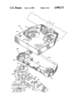
- FIG. 1 is an exploded top perspective view of the present invention showing a first typewriter ribbon cassette having a switch activating means thereon, a first correction tape cassette, a partial view of a shiftable bracket section which carries the ribbon cassette and correction tape thereon, and a partial view of the on-off switch mechanism;
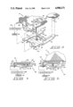
- FIG. 2 is an exploded top perspective view of the present invention showing a second typewriter ribbon cassette having a switch activating means thereon, a second correction tape cassette, a partial view of a shiftable bracket section which carries the ribbon cassette and correction tape thereon, and a partial view of the on-off switch;
- FIG. 3 is an exploded top perspective view of the present invention showing a partial view of the switch activating means located on the first typewriter ribbon cassette, a partial view of the shiftable bracket section which carries the ribbon cassette and correction tape thereon, and the on-off switch;
- FIG. 4 is a side elevational view of the present invention showing an on-off switch in its normally closed position whereby power cannot be supplied to the device;
- FIG. 5 is a side elevational view of the present invention showing an on-off switch in its normally opened position whereby power can be supplied to the device;
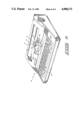
- FIG. 6 is a top perspective view of a conventional typewriter within which the present invention may be used.
- FIG. 1 a first typewriter ribbon cassette 2 having a housing 4 within which a first typewriter ribbon 6 (which may be of the single-strike carbon ribbon type), and various other components, are housed.
- a tab 8 extends from the right-hand portion of the bottom of the housing 4 for a purpose to be described hereinafter.
- a single-strike carbon ribbon is of the type which is incrementally fed in such a manner that upon a character being typed on a ribbon portion, the ribbon is advanced so that the next character is typed on a fresh portion of the ribbon.
- These components may include, among other things, a supply roll 5 upon which a typewriter ribbon supply is located, a mechanism 7 for assuring the uniform withdrawal of ribbon 6 from the supply roll 5 to the typewriter print point P (best seen in FIG. 6), and a take-up spool 9 on which the typed ribbon is located.
- a supply roll 5 upon which a typewriter ribbon supply is located may include, among other things, a mechanism 7 for assuring the uniform withdrawal of ribbon 6 from the supply roll 5 to the typewriter print point P (best seen in FIG. 6), and a take-up spool 9 on which the typed ribbon is located.
- a take-up spool 9 on which the typed ribbon is located.
- FIG. 1 there is disclosed a first correction tape cassette 10 which is functionally compatible with the first typewriter ribbon cassette 2, and within which a first correction tape 12 of, for example, the lift-off type, together with other components, is housed.
- a cassette is described in copending U.S. patent application Ser. No. 161,870 filed Feb. 29, 1988 by Hans W. Mueller, entitled “Tape Cassette for Metering Correction Tape Feed".
- the lift-off tape 12 is raised to the print point P (best seen in FIG. 6) over the character, and the unwanted character on the type element 11 of a typewriter 13 (best seen in FIG. 6) is positioned to strike the lift-off tape 12.
- Typewriter actuating means such as a typewriter key 15 (best seen in FIG. 6) causes the type element 11 to strike the lift-off tape 12 against the unwanted character on the document D, and the lift-off tape 12 withdraws the unwanted character from the document D.
- the components in the first correction tape cassette 10 may include a supply roll 17 of correcting tape 12, means 19 for assuring the uniform withdrawal of correcting tape 12 from the supply roll 17 and a take-up spool 21.
- the first correction tape cassette 10 also includes a flat portion 14 having an opening 16 in the right-hand portion, through which the tab 8 of the first typewriter ribbon cassette 2 extends when the cassettes 2, 10 are inserted into the typewriter 13.
- a functionally compatible cassette is one in which the ink ribbon in the first cassette is functionally compatible with the correction tape in the second cassette.
- FIG. 1 further discloses a shiftable bracket section 18 carrying the first typewriter ribbon cassette 2 and the first correction tape cassette 10.
- the shiftable bracket section 18 is pivotable about pivot points 20 by conventional typewriter means 23 and 25 for presenting either the first typewriter ribbon 6 or the lift-off first correction tape 12 to the typewriter print point P (best seen in FIG. 6).
- the shiftable bracket section 18 has an opening 22 and an opening 24 in a front portion 26.
- a clip 28 is clamped to the shiftable bracket section 18.
- An on-off switch rocker 30 (the operation of which will be described hereinafter) is assembled to the shiftable bracket section 18 by means of a first finger 32 of the on-off switch rocker 30 extending through the opening 24 of shiftable bracket section 18.
- a notch 34 in switch rocker 30 receives a wall portion 36 of the opening 24.
- the first finger 32 seated against the wall portion 36 provides a first pivot point for the on-off switch rocker 30.
- a second finger 38 of the on-off switch rocker 30 extends through the opening 22 in shiftable bracket section 18 and abuts against a wall portion 40 of the opening 22 to provide a second pivot point for the on-off switch rocker 30.
- the second finger 38 is integrally molded with the on-off switch rocker 30, being partially separated therefrom by a slot 39 in such a manner that the second finger 38 is laterally biased against the wall portion 40 and causes the first finger 32 to be biased against the wall portion 36 for holding the on-off switch rocker 30 assembled to the shiftable bracket section 18.
- the first pivot point of the first finger 32 is substantially in alignment with the second pivot point of the second finger 38 to provide a common axis 42 for pivoting the on-off switch rocker 30 relative to the shiftable bracket section 18.
- FIG. 2 shows a second typewriter ribbon cassette 2a and a second correction tape cassette 10a which are generally similar in construction to the first typewriter ribbon cassette 2 and the first correction tape cassette 10 shown in FIG. 1. Therefore, in large part, the same numerical reference numerals will be used in FIG. 2 as were used in FIG. 1, except that the letter "a" will be added to the reference numerals of FIG. 2.
- FIG. 2 There is shown in FIG. 2 the second typewriter ribbon cassette 2a having a housing 4a within which a second typewriter ribbon 6a, which may be of the multiple-strike carbon ribbon type, and various other components are housed.
- a tab 44 extends from the left-hand portion of the bottom of the housing 4a for the purpose to be hereinafter described.
- a multiple-strike carbon ribbon is of the type which is incrementally fed in such a manner that upon a character being typed on a ribbon portion, the ribbon is advanced so that the next character is typed on a ribbon portion comprising both a typed ribbon portion and a fresh ribbon portion.
- These components may include, among other things, a supply roll 5a upon which a typewriter ribbon supply is located, mechanism 7a for assuring the uniform withdrawal of ribbon 6a from the supply roll 5a to the typewriter print point P (best seen in FIG. 6); and a take-up spool 9a on which the typed ribbon is located.
- a supply roll 5a upon which a typewriter ribbon supply is located a supply roll 5a upon which a typewriter ribbon supply is located
- mechanism 7a for assuring the uniform withdrawal of ribbon 6a from the supply roll 5a to the typewriter print point P (best seen in FIG. 6); and a take-up spool 9a on which the typed ribbon is located.
- Such a cassette is presently being sold by Smith Corona Corporation under its "H Multi-Strike" mark.
- the second correction tape cassette 10a which is functionally compatible with the second typewriter ribbon cassette 2a, and within which a second correction tape 12a of, for example, the cover-up type, together with other components, is housed.
- a second correction tape 12a of, for example, the cover-up type together with other components.
- the cover-up tape 12a is raised to the print point P over the character, and the unwanted character on the type element 11 is positioned to strike the cover-up tape 12a.
- Typewriter actuating means 15 causes the type element 11 to strike the cover-up tape 12a against the unwanted character on document D, and the cover-up tape 12a is transferred to and covers up the unwanted character.
- the components in the second correction tape cassette 10a may include a supply roll 17a of correcting tape 12a, means 19a for assuring the uniform withdrawal of correcting tape 12a from the supply roll 17a and a take-up spool 21a.
- the second correction tape cassette 10a also includes a flat portion 14a having an opening 46 in the left-hand portion, through which the tab 44 of the second typewriter ribbon cassette 2a extends when the cassettes 2a, 10a are inserted into the typewriter 13.
- the shiftable bracket section 18 shown in FIG. 2 is the same bracket section shown in FIG. 1.
- the on-off switch rocker 30 shown in FIG. 3 includes a generally planar portion 48 having two rearwardly extending arms 50 on which an upwardly extending right-hand finger 52 and an upwardly extending left-hand finger 54 are located.
- a spring means 56 is connected at one end to the on-off switch rocker 30 and at its opposite end to the shiftable bracket section 18 at spring aperture 58. The spring 56 biases the on-off switch rocker 30 counterclockwise about the common axis 42.
- a switch 60 has a first switch contact 62 and a second switch contact 64.
- the first switch contact 62 is securely mounted on the on-off switch rocker 30.
- the first switch contact 62 has an elongated contact surface with the elongation arranged substantially parallel relative to the common axis 42.
- the second switch contact 64 is securely mounted on the clip 28 which is assembled to the shiftable bracket section 18.
- the second switch contact 64 has an elongated contact surface with the elongation arranged substantially perpendicular relative to the first switch contact 62.
- the contacts 62, 64 may be of different shapes, it has been found desirable to make the shapes elongated to reduce the manufacturing tolerances required to have the first switch contact 62 efficiently contact the second switch contact 64 during initial assembly and during continual typewriter operation thereafter.
- the first and second switch contacts 62 and 64 are connected to electronics 66 mounted in the typewriter 13 by lead lines 68.
- the electronics 66 is connected to a power source 69 for controlling the flow of electricity to the typewriter 13.
- the spring 56 biases the on-off switch rocker 30 counterclockwise relative to the shiftable bracket section 18 to bias the first switch contact 62 in contact with the second switch contact 64 for closing the switch 60.
- the switch 60 is closed when neither the first typewriter ribbon cassette 2 nor the second typewriter ribbon cassette 2a is inserted in the typewriter 13.
- the electronics 66 senses that the switch 60 is closed and thereby prevents the flow of electricity to the typewriter 13.
- the tab 8 conditions the switch 60 as it contacts the right-hand finger 52 and pivots the on-off switch rocker 30 clockwise relative to the shiftable bracket section 18 to open the switch 60.
- the tab 44 contacts the left-hand finger 54 and pivots the on-off switch rocker 30 clockwise to open the switch 60 (FIG. 2).
- the electronics 66 senses that the switch 60 is open, it permits the flow of electricity to the typewriter 13.
- the flow of electricity to the typewriter 13 will occur when the left-hand tab 44 can extend through the left-hand opening 46 in the flat portion 14a in compatible second correction tape cassette 10a. That is to say, the flow of electricity will occur when left-hand opening 46 permits left-hand tab 44 to open the switch 60. If, however, instead of second correction tape cassette 10a being present in the typewriter 13, incompatible first correction tape cassette 10 is present, which has only the right-hand opening 16 in the flat portion 14, the tab 44 cannot extend downwardly to pivot the on-off switch rocker 30 clockwise and the flow of electricity to the typewriter 13 cannot occur. Thus, it will be seen that with respect to the embodiment shown in FIGS.
- the flow of electricity will not occur when either the first typewriter ribbon cassette 2 and the second correction tape cassette 10a, or the second typewriter ribbon cassette 2a and the first correction tape cassette 10 are present in the typewriter 13.
- the combination of the right-hand tab 8 and the right-hand opening 16 or the combination of the left-hand tab 44 and the left-hand opening 46 will assure that the first and second cassettes which are inserted in the device are functionally compatible with each other.
Abstract
Description
Claims (23)
Priority Applications (15)
| Application Number | Priority Date | Filing Date | Title |
|---|---|---|---|
| US07/126,152 US4900171A (en) | 1987-11-30 | 1987-11-30 | Ink ribbon and correction tape cassette compatibility |
| JP63215341A JPH0739200B2 (en) | 1987-11-30 | 1988-08-31 | Cassette misuse prevention device and method |
| KR1019880011401A KR930004781B1 (en) | 1987-11-30 | 1988-09-03 | Ink ribbon and correction tape cassette having compatibility arrangement |
| CA000577035A CA1309371C (en) | 1987-11-30 | 1988-09-09 | Cassette compatibility |
| DE1988311368 DE319285T1 (en) | 1987-11-30 | 1988-11-30 | ADJUSTABLE CASSETTE. |
| MX013990A MX171119B (en) | 1987-11-30 | 1988-11-30 | SYSTEM AND METHOD FOR COMPATIBILITY OF INK RIBBONS AND CORRECTION RIBBONS |
| DE19883878853 DE3878853T2 (en) | 1987-11-30 | 1988-11-30 | ADJUSTABLE CASSETTE. |
| EP91201458A EP0448184B1 (en) | 1987-11-30 | 1988-11-30 | Correction tape cassette having compatibility arrangement |
| EP19880311368 EP0319285B1 (en) | 1987-11-30 | 1988-11-30 | Cassette having compatibility arrangement |
| DE19883850579 DE3850579T2 (en) | 1987-11-30 | 1988-11-30 | Correction tape cassette with compatibility device. |
| EP91201459A EP0449392B1 (en) | 1987-11-30 | 1988-11-30 | System including ink ribbon and correction tape cassettes having a compatibility arrangement |
| DE19883889673 DE3889673T2 (en) | 1987-11-30 | 1988-11-30 | System with ink ribbon and correction tape cartridges with compatibility device. |
| US07/430,107 US4971462A (en) | 1987-11-30 | 1989-11-01 | Plural cassettes having compatibility arrangement |
| US07/973,415 US5267803A (en) | 1987-11-30 | 1992-11-09 | Cassette having compatibility arrangement |
| SG62793A SG62793G (en) | 1987-11-30 | 1993-05-12 | Cassette having compatibility arrangement |
Applications Claiming Priority (1)
| Application Number | Priority Date | Filing Date | Title |
|---|---|---|---|
| US07/126,152 US4900171A (en) | 1987-11-30 | 1987-11-30 | Ink ribbon and correction tape cassette compatibility |
Related Child Applications (1)
| Application Number | Title | Priority Date | Filing Date |
|---|---|---|---|
| US21498288A Continuation-In-Part | 1987-11-30 | 1988-07-05 |
Publications (1)
| Publication Number | Publication Date |
|---|---|
| US4900171A true US4900171A (en) | 1990-02-13 |
Family
ID=22423251
Family Applications (1)
| Application Number | Title | Priority Date | Filing Date |
|---|---|---|---|
| US07/126,152 Expired - Lifetime US4900171A (en) | 1987-11-30 | 1987-11-30 | Ink ribbon and correction tape cassette compatibility |
Country Status (5)
| Country | Link |
|---|---|
| US (1) | US4900171A (en) |
| JP (1) | JPH0739200B2 (en) |
| KR (1) | KR930004781B1 (en) |
| CA (1) | CA1309371C (en) |
| MX (1) | MX171119B (en) |
Cited By (9)
| Publication number | Priority date | Publication date | Assignee | Title |
|---|---|---|---|---|
| US5069563A (en) * | 1990-06-29 | 1991-12-03 | General Ribbon Corporation | Ribbon cartridge mounting movable power switch tab |
| US5088845A (en) * | 1989-10-06 | 1992-02-18 | Brother Kogyo Kabushiki Kaisha | Ribbon cassette for mechanically unlocking a printing mechanism upon insertion of the ribbon cassette into a printing device |
| US5122002A (en) * | 1990-06-29 | 1992-06-16 | General Ribbon Corporation | Ribbon cartridge with correction cartridge lock-out circumvention power switch projection |
| US5131769A (en) * | 1991-06-28 | 1992-07-21 | Pelikan, Inc. | Ribbon cartridge |
| US5160204A (en) * | 1990-04-24 | 1992-11-03 | Canon Kabushiki Kaisha | Ribbon adapter and ribbon cassette capable of mounting the ribbon adapter and recording apparatus |
| US5490733A (en) * | 1990-04-24 | 1996-02-13 | Canon Kabushiki Kaisha | Recording apparatus and method of ink sheet type determination |
| US5533818A (en) * | 1993-12-09 | 1996-07-09 | Kroy, Inc. | Tape cartridge for a printing device |
| US20060165461A1 (en) * | 2002-12-24 | 2006-07-27 | Kris Vandermeulen | Identifying compatible combination for a thermal printer |
| USD823387S1 (en) * | 2016-08-08 | 2018-07-17 | Dover Europe Sàrl | Distance measuring guide for printer |
Citations (24)
| Publication number | Priority date | Publication date | Assignee | Title |
|---|---|---|---|---|
| US3731781A (en) * | 1968-07-16 | 1973-05-08 | Ibm | Ribbon supply cartridge |
| DE2705127A1 (en) * | 1976-04-01 | 1977-10-13 | Zentronik Veb K | CASSETTE SYSTEM, IN PARTICULAR FOR COLOR, CARBON AND CORRECTIVE TAPES |
| US4239107A (en) * | 1979-02-01 | 1980-12-16 | International Business Machines Corporation | Cartridge assembly apparatus for typewriters |
| US4247210A (en) * | 1979-10-30 | 1981-01-27 | International Business Machines Corporation | Ribbon feed and lift mechanism for a typewriter |
| JPS56144985A (en) * | 1980-04-15 | 1981-11-11 | Brother Ind Ltd | Typewriter |
| US4302118A (en) * | 1977-05-27 | 1981-11-24 | International Business Machines Corporation | Typewriter cartridge and feed mechanism therefor |
| US4329072A (en) * | 1979-10-30 | 1982-05-11 | International Business Machines Corporation | Ribbon feed and lift mechanism for a typewriter |
| US4347007A (en) * | 1977-05-27 | 1982-08-31 | International Business Machines Corporation | Typewriter cartridge and feed mechanism therefor |
| US4350453A (en) * | 1980-07-03 | 1982-09-21 | International Business Machines Corporation | Cartridge for correction media or tacky tape with a wrap spring |
| US4353651A (en) * | 1980-07-31 | 1982-10-12 | Moore William H | Method of mixing chemically bonded foundry sand by vibratory action |
| US4397575A (en) * | 1981-09-25 | 1983-08-09 | International Business Machines Corporation | Ribbon lift and feed mechanism for a typewriter |
| US4407593A (en) * | 1981-03-27 | 1983-10-04 | Nixdorf Computer Ag | Arrangement for monitoring the operation of the ink ribbon of an ink-ribbon magazine |
| JPS5978879A (en) * | 1982-10-28 | 1984-05-07 | Brother Ind Ltd | Ribbon cassette discriminator for printer |
| JPS5993376A (en) * | 1982-11-18 | 1984-05-29 | Matsushita Electric Ind Co Ltd | Printer |
| DE3346482A1 (en) * | 1982-12-28 | 1984-07-05 | Canon K.K., Tokio/Tokyo | Multi-colour recording apparatus |
| US4516137A (en) * | 1982-12-28 | 1985-05-07 | Brother Kogyo Kabushiki Kaisha | Thermal print head for heat or non-heat-sensitive paper |
| JPS6131284A (en) * | 1984-07-25 | 1986-02-13 | Hitachi Ltd | Thermal transfer printer |
| JPS61146576A (en) * | 1984-12-20 | 1986-07-04 | Ricoh Co Ltd | Line thermal transfer recorder |
| US4611936A (en) * | 1983-01-26 | 1986-09-16 | Brother Kogyo Kabushiki Kaisha | Thermal printer |
| US4611938A (en) * | 1983-01-21 | 1986-09-16 | Triumph Adler Ag | Mechanism for raising and feeding ink ribbons in typewriters and similar machines |
| US4616945A (en) * | 1985-01-31 | 1986-10-14 | International Business Machines Corporation | Correction feed mechanism in a correction tape cartridge |
| US4636097A (en) * | 1980-05-20 | 1987-01-13 | Monarch Marking Systems, Inc. | Replaceable inking cartridge with depletion counter |
| GB2179917A (en) * | 1985-09-10 | 1987-03-18 | Triumph Adler Ag | Ribbon cassette for a typewriter or other printing machines |
| US4747714A (en) * | 1985-11-07 | 1988-05-31 | Ta Triumph-Adler Aktiengesellschaft | Mechanisms for selectively raising and transporting print ribbons and correction tapes |
-
1987
- 1987-11-30 US US07/126,152 patent/US4900171A/en not_active Expired - Lifetime
-
1988
- 1988-08-31 JP JP63215341A patent/JPH0739200B2/en not_active Expired - Lifetime
- 1988-09-03 KR KR1019880011401A patent/KR930004781B1/en not_active IP Right Cessation
- 1988-09-09 CA CA000577035A patent/CA1309371C/en not_active Expired - Fee Related
- 1988-11-30 MX MX013990A patent/MX171119B/en unknown
Patent Citations (24)
| Publication number | Priority date | Publication date | Assignee | Title |
|---|---|---|---|---|
| US3731781A (en) * | 1968-07-16 | 1973-05-08 | Ibm | Ribbon supply cartridge |
| DE2705127A1 (en) * | 1976-04-01 | 1977-10-13 | Zentronik Veb K | CASSETTE SYSTEM, IN PARTICULAR FOR COLOR, CARBON AND CORRECTIVE TAPES |
| US4302118A (en) * | 1977-05-27 | 1981-11-24 | International Business Machines Corporation | Typewriter cartridge and feed mechanism therefor |
| US4347007A (en) * | 1977-05-27 | 1982-08-31 | International Business Machines Corporation | Typewriter cartridge and feed mechanism therefor |
| US4239107A (en) * | 1979-02-01 | 1980-12-16 | International Business Machines Corporation | Cartridge assembly apparatus for typewriters |
| US4329072A (en) * | 1979-10-30 | 1982-05-11 | International Business Machines Corporation | Ribbon feed and lift mechanism for a typewriter |
| US4247210A (en) * | 1979-10-30 | 1981-01-27 | International Business Machines Corporation | Ribbon feed and lift mechanism for a typewriter |
| JPS56144985A (en) * | 1980-04-15 | 1981-11-11 | Brother Ind Ltd | Typewriter |
| US4636097A (en) * | 1980-05-20 | 1987-01-13 | Monarch Marking Systems, Inc. | Replaceable inking cartridge with depletion counter |
| US4350453A (en) * | 1980-07-03 | 1982-09-21 | International Business Machines Corporation | Cartridge for correction media or tacky tape with a wrap spring |
| US4353651A (en) * | 1980-07-31 | 1982-10-12 | Moore William H | Method of mixing chemically bonded foundry sand by vibratory action |
| US4407593A (en) * | 1981-03-27 | 1983-10-04 | Nixdorf Computer Ag | Arrangement for monitoring the operation of the ink ribbon of an ink-ribbon magazine |
| US4397575A (en) * | 1981-09-25 | 1983-08-09 | International Business Machines Corporation | Ribbon lift and feed mechanism for a typewriter |
| JPS5978879A (en) * | 1982-10-28 | 1984-05-07 | Brother Ind Ltd | Ribbon cassette discriminator for printer |
| JPS5993376A (en) * | 1982-11-18 | 1984-05-29 | Matsushita Electric Ind Co Ltd | Printer |
| DE3346482A1 (en) * | 1982-12-28 | 1984-07-05 | Canon K.K., Tokio/Tokyo | Multi-colour recording apparatus |
| US4516137A (en) * | 1982-12-28 | 1985-05-07 | Brother Kogyo Kabushiki Kaisha | Thermal print head for heat or non-heat-sensitive paper |
| US4611938A (en) * | 1983-01-21 | 1986-09-16 | Triumph Adler Ag | Mechanism for raising and feeding ink ribbons in typewriters and similar machines |
| US4611936A (en) * | 1983-01-26 | 1986-09-16 | Brother Kogyo Kabushiki Kaisha | Thermal printer |
| JPS6131284A (en) * | 1984-07-25 | 1986-02-13 | Hitachi Ltd | Thermal transfer printer |
| JPS61146576A (en) * | 1984-12-20 | 1986-07-04 | Ricoh Co Ltd | Line thermal transfer recorder |
| US4616945A (en) * | 1985-01-31 | 1986-10-14 | International Business Machines Corporation | Correction feed mechanism in a correction tape cartridge |
| GB2179917A (en) * | 1985-09-10 | 1987-03-18 | Triumph Adler Ag | Ribbon cassette for a typewriter or other printing machines |
| US4747714A (en) * | 1985-11-07 | 1988-05-31 | Ta Triumph-Adler Aktiengesellschaft | Mechanisms for selectively raising and transporting print ribbons and correction tapes |
Non-Patent Citations (18)
| Title |
|---|
| IBM Technical Disclosure Bulletin, "Constant Head Wrap Tape Drive", Wenner, vol. 25, No. 4, Sep. 1982, p. 2068. |
| IBM Technical Disclosure Bulletin, "End-of-Ribbon Sensor and Cartridge-Present Indicator", Jenkins, vol. 27, No. 6, Nov. 1984, pp. 3645"3647. |
| IBM Technical Disclosure Bulletin, "Low Cost Cartridge Code Detector", Craft, vol. 25, No. 4, Sep. 1982, pp. 1980-1981. |
| IBM Technical Disclosure Bulletin, "Page Width Ribbon Cartridge and Drive Mechanism", Thorne, vol. 25, No. 4, Sep. 1982, pp. 2020-2022. |
| IBM Technical Disclosure Bulletin, "Protective Carton", Dunning et al., vol. 25, No. 4, Sep. 1982, pp. 1944-1945. |
| IBM Technical Disclosure Bulletin, "Stuffer Ribbon Cartridge", Purcell, vol. 25, No. 4, Sep. 1982, pp. 2153-2154. |
| IBM Technical Disclosure Bulletin, "Two-Color Cartridge Ribbon System With Correction", Schaefer, vol. 22, No. 6, Nov. 1979, pp. 2327-2329. |
| IBM Technical Disclosure Bulletin, "Web-Guiding Stress Functions", Winarski, vol. 25, No. 4, Sep. 1982, p. 2069. |
| IBM Technical Disclosure Bulletin, "Web-Tension Sensing Devices", Buchholz et al., vol. 25, No. 4, Sep. 1982, pp. 2066-2067. |
| IBM Technical Disclosure Bulletin, Constant Head Wrap Tape Drive , Wenner, vol. 25, No. 4, Sep. 1982, p. 2068. * |
| IBM Technical Disclosure Bulletin, End of Ribbon Sensor and Cartridge Present Indicator , Jenkins, vol. 27, No. 6, Nov. 1984, pp. 3645 3647. * |
| IBM Technical Disclosure Bulletin, Low Cost Cartridge Code Detector , Craft, vol. 25, No. 4, Sep. 1982, pp. 1980 1981. * |
| IBM Technical Disclosure Bulletin, Page Width Ribbon Cartridge and Drive Mechanism , Thorne, vol. 25, No. 4, Sep. 1982, pp. 2020 2022. * |
| IBM Technical Disclosure Bulletin, Protective Carton , Dunning et al., vol. 25, No. 4, Sep. 1982, pp. 1944 1945. * |
| IBM Technical Disclosure Bulletin, Stuffer Ribbon Cartridge , Purcell, vol. 25, No. 4, Sep. 1982, pp. 2153 2154. * |
| IBM Technical Disclosure Bulletin, Two Color Cartridge Ribbon System With Correction , Schaefer, vol. 22, No. 6, Nov. 1979, pp. 2327 2329. * |
| IBM Technical Disclosure Bulletin, Web Guiding Stress Functions , Winarski, vol. 25, No. 4, Sep. 1982, p. 2069. * |
| IBM Technical Disclosure Bulletin, Web Tension Sensing Devices , Buchholz et al., vol. 25, No. 4, Sep. 1982, pp. 2066 2067. * |
Cited By (10)
| Publication number | Priority date | Publication date | Assignee | Title |
|---|---|---|---|---|
| US5088845A (en) * | 1989-10-06 | 1992-02-18 | Brother Kogyo Kabushiki Kaisha | Ribbon cassette for mechanically unlocking a printing mechanism upon insertion of the ribbon cassette into a printing device |
| US5160204A (en) * | 1990-04-24 | 1992-11-03 | Canon Kabushiki Kaisha | Ribbon adapter and ribbon cassette capable of mounting the ribbon adapter and recording apparatus |
| US5490733A (en) * | 1990-04-24 | 1996-02-13 | Canon Kabushiki Kaisha | Recording apparatus and method of ink sheet type determination |
| US5069563A (en) * | 1990-06-29 | 1991-12-03 | General Ribbon Corporation | Ribbon cartridge mounting movable power switch tab |
| US5122002A (en) * | 1990-06-29 | 1992-06-16 | General Ribbon Corporation | Ribbon cartridge with correction cartridge lock-out circumvention power switch projection |
| US5131769A (en) * | 1991-06-28 | 1992-07-21 | Pelikan, Inc. | Ribbon cartridge |
| US5533818A (en) * | 1993-12-09 | 1996-07-09 | Kroy, Inc. | Tape cartridge for a printing device |
| US20060165461A1 (en) * | 2002-12-24 | 2006-07-27 | Kris Vandermeulen | Identifying compatible combination for a thermal printer |
| US7563044B2 (en) * | 2002-12-24 | 2009-07-21 | Dymo | Identifying compatible combination for a thermal printer |
| USD823387S1 (en) * | 2016-08-08 | 2018-07-17 | Dover Europe Sàrl | Distance measuring guide for printer |
Also Published As
| Publication number | Publication date |
|---|---|
| MX171119B (en) | 1993-10-01 |
| JPH01166980A (en) | 1989-06-30 |
| JPH0739200B2 (en) | 1995-05-01 |
| CA1309371C (en) | 1992-10-27 |
| KR930004781B1 (en) | 1993-06-08 |
| KR890007922A (en) | 1989-07-06 |
Similar Documents
| Publication | Publication Date | Title |
|---|---|---|
| US5424757A (en) | Thermal printer and cassette therefor | |
| US4900171A (en) | Ink ribbon and correction tape cassette compatibility | |
| EP0734878B1 (en) | A composite cassette including a tape cassette and a ribbon cassette | |
| JP4059282B2 (en) | Cassette and tape printer | |
| JPH09188050A (en) | Tape-ribbon complex cassette | |
| US4971462A (en) | Plural cassettes having compatibility arrangement | |
| EP0319285B1 (en) | Cassette having compatibility arrangement | |
| US3799315A (en) | Ribbon guide for typewriter ribbon cartridge | |
| US5267803A (en) | Cassette having compatibility arrangement | |
| US4422785A (en) | Ribbon cartridge construction | |
| US4729682A (en) | Document feed device with pin tractor assembly | |
| US5069563A (en) | Ribbon cartridge mounting movable power switch tab | |
| US3987885A (en) | Automatic single and repeat function mechanism for typewriters | |
| US4156573A (en) | Typewriter ribbon cartridge | |
| US5249874A (en) | Ribbon cartridge | |
| US5083877A (en) | Tape feed control apparatus for a correction tape cassette for a typewriter | |
| BR8900758A (en) | CARTRIDGE FOR PRINTING TAPE OR CORRECTION FOR WRITING MACHINES | |
| US4886385A (en) | Ribbon tensioning mechanism | |
| JPH09188051A (en) | Tape and ribbon composite cassette | |
| JPS62222872A (en) | Electronic typewriter | |
| US5122002A (en) | Ribbon cartridge with correction cartridge lock-out circumvention power switch projection | |
| GB2194217A (en) | Ink sheet cassette and recording apparatus usable with the cassette | |
| US5131769A (en) | Ribbon cartridge | |
| JPH09156188A (en) | Tape/ribbon composite cassette | |
| US3976182A (en) | Automatic function mechanism for typewriters |
Legal Events
| Date | Code | Title | Description |
|---|---|---|---|
| AS | Assignment |
Owner name: SMITH CORONA CORPORATION, A CORP. OF DE Free format text: ASSIGNMENT OF ASSIGNORS INTEREST.;ASSIGNORS:MUELLER, HANS W.;CAPPOTTO, SAMUEL D.;REEL/FRAME:004797/0849;SIGNING DATES FROM 19871124 TO 19871125 Owner name: SMITH CORONA CORPORATION, A CORP. OF,DELAWARE Free format text: ASSIGNMENT OF ASSIGNORS INTEREST;ASSIGNORS:MUELLER, HANS W.;CAPPOTTO, SAMUEL D.;SIGNING DATES FROM 19871124 TO 19871125;REEL/FRAME:004797/0849 Owner name: SMITH CORONA CORPORATION, A CORP. OF, DELAWARE Free format text: ASSIGNMENT OF ASSIGNORS INTEREST;ASSIGNORS:MUELLER, HANS W.;CAPPOTTO, SAMUEL D.;SIGNING DATES FROM 19871124 TO 19871125;REEL/FRAME:004797/0849 |
|
| STCF | Information on status: patent grant |
Free format text: PATENTED CASE |
|
| FEPP | Fee payment procedure |
Free format text: PAYOR NUMBER ASSIGNED (ORIGINAL EVENT CODE: ASPN); ENTITY STATUS OF PATENT OWNER: LARGE ENTITY |
|
| FPAY | Fee payment |
Year of fee payment: 4 |
|
| AS | Assignment |
Owner name: CHEMICAL BANK (AS AGENT), NEW YORK Free format text: SECURITY AGREEMENT;ASSIGNOR:SMITH CORONA CORPORATION;REEL/FRAME:007476/0796 Effective date: 19950407 |
|
| AS | Assignment |
Owner name: CONGRESS FINANCIAL CORPORATION, NEW YORK Free format text: SECURITY INTEREST;ASSIGNOR:SMITH CORONA CORPORATION;REEL/FRAME:008454/0131 Effective date: 19970228 |
|
| FPAY | Fee payment |
Year of fee payment: 8 |
|
| AS | Assignment |
Owner name: SMITH CORONA CORPORATION, NEW YORK Free format text: MEMORANDUM OF RELEASE;ASSIGNOR:CHASE MANHATTAN BANK, THE;REEL/FRAME:008698/0782 Effective date: 19970319 |
|
| REMI | Maintenance fee reminder mailed | ||
| FPAY | Fee payment |
Year of fee payment: 12 |
|
| SULP | Surcharge for late payment |
Year of fee payment: 11 |