US4900146A - Multiple channel optical flying spot triangulation ranger system - Google Patents
Multiple channel optical flying spot triangulation ranger system Download PDFInfo
- Publication number
- US4900146A US4900146A US07/169,707 US16970788A US4900146A US 4900146 A US4900146 A US 4900146A US 16970788 A US16970788 A US 16970788A US 4900146 A US4900146 A US 4900146A
- Authority
- US
- United States
- Prior art keywords
- light
- channels
- range
- detection channels
- ranger
- Prior art date
- Legal status (The legal status is an assumption and is not a legal conclusion. Google has not performed a legal analysis and makes no representation as to the accuracy of the status listed.)
- Expired - Fee Related
Links
Images


Classifications
-
- G—PHYSICS
- G01—MEASURING; TESTING
- G01C—MEASURING DISTANCES, LEVELS OR BEARINGS; SURVEYING; NAVIGATION; GYROSCOPIC INSTRUMENTS; PHOTOGRAMMETRY OR VIDEOGRAMMETRY
- G01C9/00—Measuring inclination, e.g. by clinometers, by levels
- G01C9/02—Details
- G01C9/06—Electric or photoelectric indication or reading means
-
- G—PHYSICS
- G01—MEASURING; TESTING
- G01S—RADIO DIRECTION-FINDING; RADIO NAVIGATION; DETERMINING DISTANCE OR VELOCITY BY USE OF RADIO WAVES; LOCATING OR PRESENCE-DETECTING BY USE OF THE REFLECTION OR RERADIATION OF RADIO WAVES; ANALOGOUS ARRANGEMENTS USING OTHER WAVES
- G01S17/00—Systems using the reflection or reradiation of electromagnetic waves other than radio waves, e.g. lidar systems
- G01S17/02—Systems using the reflection of electromagnetic waves other than radio waves
- G01S17/06—Systems determining position data of a target
- G01S17/46—Indirect determination of position data
- G01S17/48—Active triangulation systems, i.e. using the transmission and reflection of electromagnetic waves other than radio waves
-
- G—PHYSICS
- G01—MEASURING; TESTING
- G01S—RADIO DIRECTION-FINDING; RADIO NAVIGATION; DETERMINING DISTANCE OR VELOCITY BY USE OF RADIO WAVES; LOCATING OR PRESENCE-DETECTING BY USE OF THE REFLECTION OR RERADIATION OF RADIO WAVES; ANALOGOUS ARRANGEMENTS USING OTHER WAVES
- G01S17/00—Systems using the reflection or reradiation of electromagnetic waves other than radio waves, e.g. lidar systems
- G01S17/02—Systems using the reflection of electromagnetic waves other than radio waves
- G01S17/06—Systems determining position data of a target
- G01S17/42—Simultaneous measurement of distance and other co-ordinates
Definitions
- This invention relates to a time-based optical triangulation system and especially to improvements to increase the speed of acquiring range valves.
- a swept aperture flying spot optical ranging instrument has been developed and was offered as a product known as the MIG TRAK TM welding seam tracker. It is described in U.S. Pat. No. 4,645,917 --Penney, Roy and Thomas and U.S. Pat. No. 4,701,031 --Penney and Thomas. Although it provides the highest quality data among developed ranging systems, the maximum rate at which this type of system can acquire data is limited by the beam deflecting acousto-optic cell to less than 100,000 range elements per second, and in fact runs at about 20,000 range measurements per second. To our knowledge no other developed system runs significantly faster.
- the speed of measuring range points in a swept aperture flying spot triangulation ranger is increased by adding additional detector channels, each of which observes the surface at a different sensitive zone along the line which forms the intersection of the swept beam with the surface. Since all of the channels make use of the same swept beam, the beam source and deflector are used more efficiently, providing N range points per beam sweep, where N is the number of channels, rather than only one.
- the improved flying spot triangulation ranger system is comprised of: means for providing a light beam and rapidly sweeping this beam across a surface in a given direction; multiple light detection channels optically coupled to separate detectors; and receiving lens means for focusing images of the light spot onto the entrance faces of the adjacent detection channels.
- the respective detector As the light spot generated by the scanned beam crosses a small sensitive zone on the surface from which a detection channel can receive light, the respective detector generates an electrical signal pulse. These pulses are output at times that are a function of range to the surface; for every sweep of the light beam there are a plurality of range measurements equal to the number of detection channels.
- the detection channels are preferably separate noncoherent fiber optic bundles, but may be solid glass, and typically there are ten to twenty such channels.
- the entrance faces of the detection channels may be rectangular or square, and the sensitive zones "visible" to the channels have corresponding shapes.
- the detectors may be photomultipliers.
- Another aspect of the invention is a multiple channel flying spot triangulation ranger system comprised of a laser beam source and means for deflecting and sweeping the beam across the surface in the X direction; multiple fiber optic light detection channels each receiving light from a different sensitive zone along a scanned line; and a receiving lens.
- Separate detectors sense the light delivered by the fiber optic channels and generate signal pulses, one per channel, at times respectively related to range to the surface. Means are provided for processing these signal pulses in parallel and calculating multiple range values.
- an aperture stop plate between the receiving lens and light detection channels having a rectangular slit to limit passage of light and increase depth of focus.
- Mirror means such as polygons, may be provided to scan the laser beam in the Y direction coordinated with the X direction sweep.
- the processing means calculates range values after each beam sweep, covering a strip of the surface, before stepping a table to scan adjacent strips.
- FIG. 1 shows the prior art swept aperture flying spot ranging system.
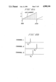
- FIG. 2 (prior art) are graphs illustrating the X direction scan and electrical signal pulses generated by the scanned beam at two surface heights.
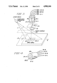
- FIG. 3 shows the improved flying spot triangulation ranger having a multiple channel light detector.
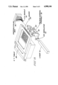
- FIG. 4 is a perspective view of the multichannel light detector assembly.
- FIGS. 5 and 6 show two embodiments of the light detector respectively having fiber optic and solid glass channels.
- FIG. 7 illustrates the scan motions used in scanning an object.
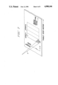
- FIG. 8 is a perspective view of an embodiment of the improved range camera to inspect printed circuit boards.
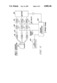
- FIG. 9 is a simplified block diagram showing parallel processing of the channel light detector signals to obtain range values.
- FIGS. 10a and 10b show the X direction acousto-optic deflector scan and the electrical pulses generated by each channel at times dependent on range.
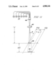
- FIG. 11 shows a portion of the multiple channel swept aperture ranger and the required increase in scan length.
- a beam of light L is swept by beam deflector 10 along a line across the observed surface 11 over the time t 0 to t 1 .
- the intersection point of the beam with the surface a spot of light, passes through the region 12 viewed by the lens 13 and aperture 14; the latter is at the focal point of the receiving lens. Consequently, the scattered light from the point reaches the detector, photomultiplier 15, which puts out a sharp signal pulse at the time t z .
- An electronic system analyzes this signal to derive a second signal encoding the time of the pulse.
- the time at which the pulse is observed is a function of the range to the surface, and in fact varies nearly linearly with this range.
- this system provides range information in the form of an encoded pulse time. If the surface is lowered by an amount ⁇ Z, then the position in time of the corresponding detected electrical signal pulse will shift to the left in time as is seen by comparing lines (b) and (c) in FIG. 2. By measuring the time shift ⁇ T the flying spot triangulation system can measure the change in range.
- the light beam is swept across the surface very rapidly at constant velocity, usually by an acousto-optic modulator beam deflector, such that range measurements can be obtained very rapidly, at rates at least up to 20,000 range measurements per second. Nevertheless, even this high speed is insufficient for some applications, including many that are motivating the development of 3-D cameras.
- FIG. 3 shows the multiple channel optical flying spot triangulation ranger of this invention.
- a significant increase in speed is achieved by adding additional detector channels, each of which observes the surface at a different point along the line which forms the intersection of the swept beam with the surface.
- Four light detection channels are illustrated, but ten to twenty channels are feasible and a reasonable upper limit is thirty to forty channels. All of the detection channels make use of the same swept beam L, but there are now N range points per beam sweep, where N is the number of channels. Only the receiver channels must be duplicated to achieve the increased speed.
- a laser (not shown) generates a narrow laser beam that is presented to acousto-optic beam deflector 16 and rapidly scanned across the surface 17 in the X direction.
- a single spherical receiving lens 18 or a compound lens serves all of the light detection channels 19-1 to 19-4, the ends of which are encapsulated in a plastic plug 20.
- the ends of the light transmitting channels extend out of the plug 20 and deliver light to four separate light detectors 21-1 to 21-4.
- These may be photomultipliers, certain types of photodiodes, or other solid state light detectors. Photomultipliers are a good choice because they have ideal light detection qualities, i.e. excellent sensitivity and wide dynamic range.
- an aperture stop plate 22 between the receiving lens 18 and the light detection channels having a rectangular slit 23 to pass light.
- This slit is relatively large, say 0.125" ⁇ 1.000", and functions to increase the depth of focus and limit passage of light, much like the f/stop on a camera.
- This slit does not serve the same purpose as aperture 14 in the prior art single channel instrument, and is not an essential part of the system.
- Light detection channel 19-1 receives light only from the sensitive zone 24-1 on surface 17, and the other three channels respectively from the sensitive zones 24-2, 24-3, and 24-4.
- the shape of these sensitive zones is approximately the same as the entrance faces of the light detection channels and the size of the zones is governed by the magnification of the optical system.
- a square or rectangular entrance face geometry is ideal; a small aperture is desired in the X direction and the longer Y dimension in the rectangular case gives freedom to align.
- FIG. 5 shows the use of fiber optic bundle technology to create the adjacent fiber optic channels 19-1 to 19-4.
- Each channel is comprised of a noncoherent fiber optic bundle, rectangular at the entrance and gathered together toward the other end to make a flexible, roughly circular bundle that can be routed to the photomultiplier box.
- FIG. 6 shows solid glass light transmitting channels 26-1 to 26-4.
- FST flying spot triangulation
- FIG. 7 The scanning of a larger area on an object by coordinated X and Y scans, followed by indexing of a table on which the object rests to scan other strips on the object surface, is illustrated in FIG. 7.
- the beam deflector 16 in FIG. 3 sweeps the laser beam L along a line in the X direction as was previously described. As the laser beam L enters and crosses the four sensitive zones 27, the respective light detection channels generate output signal pulses at times that are a function of range to the surface. Thus there are four range points per beam scan. Then a Y scan mirror 28 shown schematically in FIG.
- strip 3 scans the beam in the Y direction and a second X scan beam scan is made to obtain four more range measurements. If strip 1 has 500 X beam sweeps and there are 4 range points per sweep, the total from strip 1 is 2000 range points. The table is now stepped in the X direction and strip 2 on the object surface is scanned, and so on.
- FIG. 8 is a perspective drawing of the entire range camera and X-Y table arrangement to inspect a printed wiring board.
- These boards consist of a thin planar sheet on which are mounted electronic components such as integrated circuits, resistors and capacitors. These components are interconnected by conductors on the board surface or by sets of conductors within the plane of the board.
- the X-Y table 28 holds the printed circuit board 29 with the bottom, lead side facing down towards the optical head and parallel to the X-Y plane. The table scans the active measurement region over the entire surface of the printed circuit board.
- the polygon mirrors assembly 30 rotates at a constant velocity and operates to Y scan the laser beam and as a Y descanner for the receiving optics.
- the narrow beam generated by a laser 31 is deflected by the acousto-optic modulator 32 to perform the X scan.
- the swept beam is reflected by folding mirrors onto the first polygon mirror 33 and hence sweeps across the surface of board 29.
- the reflected beam is descanned by the second polygon mirror 34, focused by lens 50, and reflected by a mirror to the multichannel fiber optic bundles 35 which deliver light to the photomultiplier box 36.
- the signal processing electronics block diagram in FIG. 9 illustrates parallel processing of the detector output signals and computation of range values.
- the multichannel light detector assembly 37 has three channels and, looking at one channel, the others being the same, the signal pulse from photomultiplier 38 is converted to a voltage and conditioned in amplifier 39 and digitized at 40.
- Digital signal processor 41 produces the best estimate of the time signal after rejecting any possible range clutter and noise impulses, accounts for variations in surface reflectivity and luminance, and calculates range or height of the surface.
- the three computed range values are presented to buffer 42 and hence read out to the range computer 43. When all the range measurements are stored, a range image may be output.
- the range computer coordinates the timing of the system and acousto-optic beam deflector 44, and may have other functions such as coordinate conversion.
- the period T of one acousto-optic sweep is, for instance, 50-60 microseconds and is divided into time segments corresponding to beam angle.
- the start of sweep (SOS) and end of sweep (EOS) are sent to digital processor 41 as well as the sample clock (SC).
- SC sample clock
- the detector signal pulse occurs at times t 1 , t 2 and t 3 , respectively, measured from the start of sweep. These times are a function of range to the surface at those range points.
- this time determines the angle of the swept beam and knowing the angle of the reflected beam, optical triangulation yields the range.
- N range values are determined where N is the number of detection channels.
- a practical upper limit to the total number of channels may be in the order of 30-40 channels.
- One consideration is the complexity introduced by a large number of detectors and time analysis electronics.
- Another limit is the required increase in scan length. This derives from the relationship between scan length and stripe length.
- N 6
- the light beam L is shown scanned parallel and swept over the surface from time t 0 time to t 1 .
- the image of the multiple detection channels on the surface at the closest design range is shown at 48, and the image at farthest design range at 49.
- S is much smaller than L, such that an insignificant change in sweep length is required to accommodate the additional channels. But as N is increased, the sweep length must be increased substantially, according to equation (1). This spreads out the light, weakening the signal to each channel.
- fast scanners such as acousto-optic cells provide a limited number of resolution spots. If the scan is spread out too far, the scanned spot will have an instantaneous width greater than the resolved spot, further weakening the signal. Despite these limitations a very large improvement in data rate is realized within the scanned aperture configuration.
Abstract
Description
L.sub.N =L.sub.1 +S (1)
Claims (11)
Priority Applications (4)
| Application Number | Priority Date | Filing Date | Title |
|---|---|---|---|
| US07/169,707 US4900146A (en) | 1988-03-18 | 1988-03-18 | Multiple channel optical flying spot triangulation ranger system |
| KR1019890003155A KR970007040B1 (en) | 1988-03-18 | 1989-03-15 | Multiple cannel opitical flying spot triangulation ranger system |
| JP1063982A JPH01311206A (en) | 1988-03-18 | 1989-03-17 | Multichannel optical type flying spot triangulation distance measuring apparatus |
| EP19890302638 EP0333493A3 (en) | 1988-03-18 | 1989-03-17 | Triangulation system |
Applications Claiming Priority (1)
| Application Number | Priority Date | Filing Date | Title |
|---|---|---|---|
| US07/169,707 US4900146A (en) | 1988-03-18 | 1988-03-18 | Multiple channel optical flying spot triangulation ranger system |
Publications (1)
| Publication Number | Publication Date |
|---|---|
| US4900146A true US4900146A (en) | 1990-02-13 |
Family
ID=22616844
Family Applications (1)
| Application Number | Title | Priority Date | Filing Date |
|---|---|---|---|
| US07/169,707 Expired - Fee Related US4900146A (en) | 1988-03-18 | 1988-03-18 | Multiple channel optical flying spot triangulation ranger system |
Country Status (4)
| Country | Link |
|---|---|
| US (1) | US4900146A (en) |
| EP (1) | EP0333493A3 (en) |
| JP (1) | JPH01311206A (en) |
| KR (1) | KR970007040B1 (en) |
Cited By (19)
| Publication number | Priority date | Publication date | Assignee | Title |
|---|---|---|---|---|
| US5032023A (en) * | 1990-07-02 | 1991-07-16 | General Electric Company | Optical fiber based sensor for a variable depth range camera |
| US5088828A (en) * | 1989-02-28 | 1992-02-18 | Siemens Aktiengesellschaft | Method and apparatus for three-dimensional testing of printed circuitboards |
| US5570183A (en) * | 1995-04-24 | 1996-10-29 | Ati Systems, Inc. | Apparatus for measuring optical characteristics of a surface in two dimensions using a moving light source |
| US5615003A (en) * | 1994-11-29 | 1997-03-25 | Hermary; Alexander T. | Electromagnetic profile scanner |
| US5768461A (en) * | 1995-11-02 | 1998-06-16 | General Scanning, Inc. | Scanned remote imaging method and system and method of determining optimum design characteristics of a filter for use therein |
| US5831621A (en) * | 1996-10-21 | 1998-11-03 | The Trustees Of The University Of Pennyslvania | Positional space solution to the next best view problem |
| US5917600A (en) * | 1997-06-18 | 1999-06-29 | Cybo Robots, Inc | Displacement sensor |
| US5956134A (en) * | 1997-07-11 | 1999-09-21 | Semiconductor Technologies & Instruments, Inc. | Inspection system and method for leads of semiconductor devices |
| US6118540A (en) * | 1997-07-11 | 2000-09-12 | Semiconductor Technologies & Instruments, Inc. | Method and apparatus for inspecting a workpiece |
| DE19961955A1 (en) * | 1999-12-24 | 2001-07-05 | Hannover Laser Zentrum | Measuring method for gap between measurement device and measurement surface, involves computing gap between detector and radiation point of laser through trigonometrical calculation |
| US6654115B2 (en) | 2001-01-18 | 2003-11-25 | Orbotech Ltd. | System and method for multi-dimensional optical inspection |
| US6705526B1 (en) | 1995-12-18 | 2004-03-16 | Metrologic Instruments, Inc. | Automated method of and system for dimensioning objects transported through a work environment using contour tracing, vertice detection, corner point detection, and corner point reduction methods on two-dimensional range data maps captured by an amplitude modulated laser scanning beam |
| US6870611B2 (en) | 2001-07-26 | 2005-03-22 | Orbotech Ltd. | Electrical circuit conductor inspection |
| US6971580B2 (en) | 1999-06-07 | 2005-12-06 | Metrologic Instruments, Inc. | Automated method of and system for dimensioning objects over a conveyor belt structure by applying contouring tracing, vertice detection, corner point detection, and corner point reduction methods to two-dimensional range data maps of the space above the conveyor belt captured by an amplitude modulated laser scanning beam |
| US20060151604A1 (en) * | 2002-01-02 | 2006-07-13 | Xiaoxun Zhu | Automated method of and system for dimensioning objects over a conveyor belt structure by applying contouring tracing, vertice detection, corner point detection, and corner point reduction methods to two-dimensional range data maps of the space above the conveyor belt captured by an amplitude modulated laser scanning beam |
| US20070007432A1 (en) * | 2004-01-25 | 2007-01-11 | Man Roland Druckmaschinen Ag | Apparatus and method for acquiring and evaluating an image from a predetermined extract of a printed product |
| DE102009040990A1 (en) * | 2009-09-10 | 2011-03-17 | Carl Zeiss Ag | Device for measuring upper surface, comprises light control unit, which is arranged on upper surface to control optical signal in ray fan, where optical signal comprises cycle of light pulses with repetition rate |
| US20140009762A1 (en) * | 2012-06-21 | 2014-01-09 | Nikon Corporation | Measurement assembly with fiber optic array |
| US8812149B2 (en) | 2011-02-24 | 2014-08-19 | Mss, Inc. | Sequential scanning of multiple wavelengths |
Families Citing this family (2)
| Publication number | Priority date | Publication date | Assignee | Title |
|---|---|---|---|---|
| DE4422414A1 (en) * | 1994-06-29 | 1996-01-04 | Bfi Entsorgungstech | Optical monitoring arrangement |
| KR100940259B1 (en) * | 2008-01-21 | 2010-02-04 | (주)클래시스 | Laser apparatus able to output multi-laser beam |
Citations (9)
| Publication number | Priority date | Publication date | Assignee | Title |
|---|---|---|---|---|
| US3746454A (en) * | 1971-03-03 | 1973-07-17 | Us Navy | Infrared receiver for optical radar |
| US3953131A (en) * | 1973-03-02 | 1976-04-27 | Hans Ernst Britz | Opto-electronic antenna system for lasers |
| US4227812A (en) * | 1977-03-10 | 1980-10-14 | Centre De Recherches Metallurgiques Centrum Voor Research In De Metallurgie | Method of determining a dimension of an article |
| US4583857A (en) * | 1982-02-06 | 1986-04-22 | International Business Machines Corporation | Apparatus for automatic optical property testing |
| US4645917A (en) * | 1985-05-31 | 1987-02-24 | General Electric Company | Swept aperture flying spot profiler |
| US4701031A (en) * | 1986-05-29 | 1987-10-20 | General Electric Company | Prism telescope to match optical requirements for acousto-optic deflector |
| US4790660A (en) * | 1986-10-03 | 1988-12-13 | Ntt Technology Transfer Corporation | Shape measuring instrument |
| US4794262A (en) * | 1985-12-03 | 1988-12-27 | Yukio Sato | Method and apparatus for measuring profile of three-dimensional object |
| US4830485A (en) * | 1987-11-23 | 1989-05-16 | General Electric Company | Coded aperture light detector for three dimensional camera |
Family Cites Families (4)
| Publication number | Priority date | Publication date | Assignee | Title |
|---|---|---|---|---|
| JPS5745406A (en) * | 1980-09-03 | 1982-03-15 | Hitachi Ltd | Three-dimensional coordinate measuring device |
| DE3044831A1 (en) * | 1980-11-28 | 1982-06-24 | Fraunhofer-Gesellschaft zur Förderung der angewandten Forschung e.V., 8000 München | Automatic optical position detection system - uses coaxial scanning and measuring beams to form three=dimensional image |
| JPS59129809A (en) * | 1983-01-18 | 1984-07-26 | Asahi Optical Co Ltd | Automatic focusing device of camera |
| US4708483A (en) * | 1985-06-28 | 1987-11-24 | Rexnord Inc. | Optical measuring apparatus and method |
-
1988
- 1988-03-18 US US07/169,707 patent/US4900146A/en not_active Expired - Fee Related
-
1989
- 1989-03-15 KR KR1019890003155A patent/KR970007040B1/en active IP Right Grant
- 1989-03-17 JP JP1063982A patent/JPH01311206A/en active Pending
- 1989-03-17 EP EP19890302638 patent/EP0333493A3/en not_active Withdrawn
Patent Citations (9)
| Publication number | Priority date | Publication date | Assignee | Title |
|---|---|---|---|---|
| US3746454A (en) * | 1971-03-03 | 1973-07-17 | Us Navy | Infrared receiver for optical radar |
| US3953131A (en) * | 1973-03-02 | 1976-04-27 | Hans Ernst Britz | Opto-electronic antenna system for lasers |
| US4227812A (en) * | 1977-03-10 | 1980-10-14 | Centre De Recherches Metallurgiques Centrum Voor Research In De Metallurgie | Method of determining a dimension of an article |
| US4583857A (en) * | 1982-02-06 | 1986-04-22 | International Business Machines Corporation | Apparatus for automatic optical property testing |
| US4645917A (en) * | 1985-05-31 | 1987-02-24 | General Electric Company | Swept aperture flying spot profiler |
| US4794262A (en) * | 1985-12-03 | 1988-12-27 | Yukio Sato | Method and apparatus for measuring profile of three-dimensional object |
| US4701031A (en) * | 1986-05-29 | 1987-10-20 | General Electric Company | Prism telescope to match optical requirements for acousto-optic deflector |
| US4790660A (en) * | 1986-10-03 | 1988-12-13 | Ntt Technology Transfer Corporation | Shape measuring instrument |
| US4830485A (en) * | 1987-11-23 | 1989-05-16 | General Electric Company | Coded aperture light detector for three dimensional camera |
Cited By (25)
| Publication number | Priority date | Publication date | Assignee | Title |
|---|---|---|---|---|
| US5088828A (en) * | 1989-02-28 | 1992-02-18 | Siemens Aktiengesellschaft | Method and apparatus for three-dimensional testing of printed circuitboards |
| US5032023A (en) * | 1990-07-02 | 1991-07-16 | General Electric Company | Optical fiber based sensor for a variable depth range camera |
| US5986745A (en) * | 1994-11-29 | 1999-11-16 | Hermary; Alexander Thomas | Co-planar electromagnetic profile scanner |
| US5615003A (en) * | 1994-11-29 | 1997-03-25 | Hermary; Alexander T. | Electromagnetic profile scanner |
| US5570183A (en) * | 1995-04-24 | 1996-10-29 | Ati Systems, Inc. | Apparatus for measuring optical characteristics of a surface in two dimensions using a moving light source |
| US5768461A (en) * | 1995-11-02 | 1998-06-16 | General Scanning, Inc. | Scanned remote imaging method and system and method of determining optimum design characteristics of a filter for use therein |
| US5822486A (en) * | 1995-11-02 | 1998-10-13 | General Scanning, Inc. | Scanned remote imaging method and system and method of determining optimum design characteristics of a filter for use therein |
| US6705526B1 (en) | 1995-12-18 | 2004-03-16 | Metrologic Instruments, Inc. | Automated method of and system for dimensioning objects transported through a work environment using contour tracing, vertice detection, corner point detection, and corner point reduction methods on two-dimensional range data maps captured by an amplitude modulated laser scanning beam |
| US5831621A (en) * | 1996-10-21 | 1998-11-03 | The Trustees Of The University Of Pennyslvania | Positional space solution to the next best view problem |
| US5917600A (en) * | 1997-06-18 | 1999-06-29 | Cybo Robots, Inc | Displacement sensor |
| US5956134A (en) * | 1997-07-11 | 1999-09-21 | Semiconductor Technologies & Instruments, Inc. | Inspection system and method for leads of semiconductor devices |
| US6118540A (en) * | 1997-07-11 | 2000-09-12 | Semiconductor Technologies & Instruments, Inc. | Method and apparatus for inspecting a workpiece |
| US6971580B2 (en) | 1999-06-07 | 2005-12-06 | Metrologic Instruments, Inc. | Automated method of and system for dimensioning objects over a conveyor belt structure by applying contouring tracing, vertice detection, corner point detection, and corner point reduction methods to two-dimensional range data maps of the space above the conveyor belt captured by an amplitude modulated laser scanning beam |
| DE19961955A1 (en) * | 1999-12-24 | 2001-07-05 | Hannover Laser Zentrum | Measuring method for gap between measurement device and measurement surface, involves computing gap between detector and radiation point of laser through trigonometrical calculation |
| US7006212B2 (en) | 2000-10-04 | 2006-02-28 | Orbotech Ltd. | Electrical circuit conductor inspection |
| US20050134842A1 (en) * | 2000-10-04 | 2005-06-23 | Orbotech, Ltd. | Electrical circuit conductor inspection |
| US6654115B2 (en) | 2001-01-18 | 2003-11-25 | Orbotech Ltd. | System and method for multi-dimensional optical inspection |
| US6870611B2 (en) | 2001-07-26 | 2005-03-22 | Orbotech Ltd. | Electrical circuit conductor inspection |
| US20060151604A1 (en) * | 2002-01-02 | 2006-07-13 | Xiaoxun Zhu | Automated method of and system for dimensioning objects over a conveyor belt structure by applying contouring tracing, vertice detection, corner point detection, and corner point reduction methods to two-dimensional range data maps of the space above the conveyor belt captured by an amplitude modulated laser scanning beam |
| US7344082B2 (en) | 2002-01-02 | 2008-03-18 | Metrologic Instruments, Inc. | Automated method of and system for dimensioning objects over a conveyor belt structure by applying contouring tracing, vertice detection, corner point detection, and corner point reduction methods to two-dimensional range data maps of the space above the conveyor belt captured by an amplitude modulated laser scanning beam |
| US20070007432A1 (en) * | 2004-01-25 | 2007-01-11 | Man Roland Druckmaschinen Ag | Apparatus and method for acquiring and evaluating an image from a predetermined extract of a printed product |
| US7501647B2 (en) * | 2004-01-25 | 2009-03-10 | Manroland Ag | Apparatus and method for acquiring and evaluating an image from a predetermined extract of a printed product |
| DE102009040990A1 (en) * | 2009-09-10 | 2011-03-17 | Carl Zeiss Ag | Device for measuring upper surface, comprises light control unit, which is arranged on upper surface to control optical signal in ray fan, where optical signal comprises cycle of light pulses with repetition rate |
| US8812149B2 (en) | 2011-02-24 | 2014-08-19 | Mss, Inc. | Sequential scanning of multiple wavelengths |
| US20140009762A1 (en) * | 2012-06-21 | 2014-01-09 | Nikon Corporation | Measurement assembly with fiber optic array |
Also Published As
| Publication number | Publication date |
|---|---|
| EP0333493A3 (en) | 1991-07-03 |
| KR970007040B1 (en) | 1997-05-02 |
| KR890014994A (en) | 1989-10-28 |
| EP0333493A2 (en) | 1989-09-20 |
| JPH01311206A (en) | 1989-12-15 |
Similar Documents
| Publication | Publication Date | Title |
|---|---|---|
| US4900146A (en) | Multiple channel optical flying spot triangulation ranger system | |
| US4830485A (en) | Coded aperture light detector for three dimensional camera | |
| US5991040A (en) | Optical distance sensor | |
| KR950006035B1 (en) | Method and system for determining surface profile information | |
| US5177556A (en) | Three dimensional color imaging | |
| KR100706135B1 (en) | Method and system for imaging an object with a plurality of optical beams | |
| JP2919267B2 (en) | Shape detection method and device | |
| JP3213003B2 (en) | Validation method of optical distance measurement of target surface in disturbed environment | |
| US4899041A (en) | Light sensor for detecting an object in a certain distance | |
| US4983827A (en) | Linescan apparatus for detecting salient pattern of a product | |
| JP2510786B2 (en) | Object shape detection method and apparatus | |
| EP0498495A1 (en) | Device for optically measuring the height of a surface | |
| US5723869A (en) | Multichannel position sensing detector | |
| EP0882211A1 (en) | A method and apparatus for reducing the unwanted effects of noise present in a three-dimensional color imaging system | |
| US4629885A (en) | Scanning apparatus | |
| CA2003753A1 (en) | Multiple channel optical flying spot trianglation ranger system | |
| US4871910A (en) | Method and apparatus for measuring the size of wire rod with laser beam and reference rod | |
| US7212294B2 (en) | Method for determination of the level of two or more measurement points, and an arrangement for this purpose | |
| US4948967A (en) | Method for detecting a position receiving a light beam | |
| US5673111A (en) | Method and arrangement for measuring distance | |
| CA2043336C (en) | Three dimensional colour imaging | |
| US4533828A (en) | Arrangement for increasing the dynamic range of optical inspection devices to accommodate varying surface reflectivity characteristics | |
| DE19624751A1 (en) | Duration time measuring process using continuous light beam | |
| JPH07117395B2 (en) | Optical measuring device for measuring three-dimensional objects | |
| JP2510786C (en) |
Legal Events
| Date | Code | Title | Description |
|---|---|---|---|
| AS | Assignment |
Owner name: GENERAL ELECTRIC COMPANY, A NEW YORK CORP. Free format text: ASSIGNMENT OF ASSIGNORS INTEREST.;ASSIGNORS:PENNEY, CARL M.;CORBY, NELSON R. JR.;IRWIN, NANCY H.;REEL/FRAME:004854/0155;SIGNING DATES FROM 19880229 TO 19880314 Owner name: GENERAL ELECTRIC COMPANY, NEW YORK Free format text: ASSIGNMENT OF ASSIGNORS INTEREST;ASSIGNORS:PENNEY, CARL M.;CORBY, NELSON R. JR.;IRWIN, NANCY H.;SIGNING DATES FROM 19880229 TO 19880314;REEL/FRAME:004854/0155 |
|
| FEPP | Fee payment procedure |
Free format text: PAYOR NUMBER ASSIGNED (ORIGINAL EVENT CODE: ASPN); ENTITY STATUS OF PATENT OWNER: LARGE ENTITY |
|
| AS | Assignment |
Owner name: LINCOLN ELECTRIC COMPANY, THE, OHIO Free format text: ASSIGNMENT OF ASSIGNORS INTEREST.;ASSIGNOR:GENERAL ELECTRIC COMPANY, A CORP. OF NY;REEL/FRAME:006198/0610 Effective date: 19920716 |
|
| FEPP | Fee payment procedure |
Free format text: PAYER NUMBER DE-ASSIGNED (ORIGINAL EVENT CODE: RMPN); ENTITY STATUS OF PATENT OWNER: LARGE ENTITY Free format text: PAYOR NUMBER ASSIGNED (ORIGINAL EVENT CODE: ASPN); ENTITY STATUS OF PATENT OWNER: LARGE ENTITY |
|
| FPAY | Fee payment |
Year of fee payment: 4 |
|
| FPAY | Fee payment |
Year of fee payment: 8 |
|
| REMI | Maintenance fee reminder mailed | ||
| LAPS | Lapse for failure to pay maintenance fees | ||
| STCH | Information on status: patent discontinuation |
Free format text: PATENT EXPIRED DUE TO NONPAYMENT OF MAINTENANCE FEES UNDER 37 CFR 1.362 |
|
| FP | Lapsed due to failure to pay maintenance fee |
Effective date: 20020213 |