US4900130A - Method of scanning - Google Patents
Method of scanning Download PDFInfo
- Publication number
- US4900130A US4900130A US07/254,745 US25474588A US4900130A US 4900130 A US4900130 A US 4900130A US 25474588 A US25474588 A US 25474588A US 4900130 A US4900130 A US 4900130A
- Authority
- US
- United States
- Prior art keywords
- array
- raster lines
- medium
- elements
- lines
- Prior art date
- Legal status (The legal status is an assumption and is not a legal conclusion. Google has not performed a legal analysis and makes no representation as to the accuracy of the status listed.)
- Expired - Lifetime
Links
Images
Classifications
-
- H—ELECTRICITY
- H04—ELECTRIC COMMUNICATION TECHNIQUE
- H04N—PICTORIAL COMMUNICATION, e.g. TELEVISION
- H04N1/00—Scanning, transmission or reproduction of documents or the like, e.g. facsimile transmission; Details thereof
- H04N1/04—Scanning arrangements, i.e. arrangements for the displacement of active reading or reproducing elements relative to the original or reproducing medium, or vice versa
- H04N1/19—Scanning arrangements, i.e. arrangements for the displacement of active reading or reproducing elements relative to the original or reproducing medium, or vice versa using multi-element arrays
- H04N1/191—Scanning arrangements, i.e. arrangements for the displacement of active reading or reproducing elements relative to the original or reproducing medium, or vice versa using multi-element arrays the array comprising a one-dimensional array, or a combination of one-dimensional arrays, or a substantially one-dimensional array, e.g. an array of staggered elements
- H04N1/1911—Simultaneously or substantially simultaneously scanning picture elements on more than one main scanning line, e.g. scanning in swaths
- H04N1/1912—Scanning main scanning lines which are spaced apart from one another in the sub-scanning direction
-
- G—PHYSICS
- G06—COMPUTING; CALCULATING OR COUNTING
- G06K—GRAPHICAL DATA READING; PRESENTATION OF DATA; RECORD CARRIERS; HANDLING RECORD CARRIERS
- G06K15/00—Arrangements for producing a permanent visual presentation of the output data, e.g. computer output printers
- G06K15/02—Arrangements for producing a permanent visual presentation of the output data, e.g. computer output printers using printers
- G06K15/12—Arrangements for producing a permanent visual presentation of the output data, e.g. computer output printers using printers by photographic printing, e.g. by laser printers
- G06K15/1238—Arrangements for producing a permanent visual presentation of the output data, e.g. computer output printers using printers by photographic printing, e.g. by laser printers simultaneously exposing more than one point
- G06K15/1257—Arrangements for producing a permanent visual presentation of the output data, e.g. computer output printers using printers by photographic printing, e.g. by laser printers simultaneously exposing more than one point on more than one main scanning line
- G06K15/1261—Arrangements for producing a permanent visual presentation of the output data, e.g. computer output printers using printers by photographic printing, e.g. by laser printers simultaneously exposing more than one point on more than one main scanning line using an array of light sources
-
- G—PHYSICS
- G06—COMPUTING; CALCULATING OR COUNTING
- G06K—GRAPHICAL DATA READING; PRESENTATION OF DATA; RECORD CARRIERS; HANDLING RECORD CARRIERS
- G06K2215/00—Arrangements for producing a permanent visual presentation of the output data
- G06K2215/111—Arrangements for producing a permanent visual presentation of the output data with overlapping swaths
-
- Y—GENERAL TAGGING OF NEW TECHNOLOGICAL DEVELOPMENTS; GENERAL TAGGING OF CROSS-SECTIONAL TECHNOLOGIES SPANNING OVER SEVERAL SECTIONS OF THE IPC; TECHNICAL SUBJECTS COVERED BY FORMER USPC CROSS-REFERENCE ART COLLECTIONS [XRACs] AND DIGESTS
- Y10—TECHNICAL SUBJECTS COVERED BY FORMER USPC
- Y10S—TECHNICAL SUBJECTS COVERED BY FORMER USPC CROSS-REFERENCE ART COLLECTIONS [XRACs] AND DIGESTS
- Y10S359/00—Optical: systems and elements
- Y10S359/90—Methods
Definitions
- the present invention relates to a method of scanning in an optical device, and more particularly to such a method which is adapted to produce a high resolution image.
- Exposure systems for recording information on a light-sensitive recording medium often employ multiple radiation sources operating in parallel to decrease the aggregate amount of time required to complete the exposure.
- U. S. Pat. No. 4,389,655 there is shown an optical device for non-impact recording in which a recording head includes a linear array of optical fibers. A recording medium is moved relative to the recording head, and the fibers of the head are arranged with their output ends extending in a direction transverse to the direction of movement of the recording medium. A light source is connected to each of the fibers at an input end, and each of the light sources is modulated in accordance with an information signal to produce a desired image.
- a problem with devices of the type shown in this patent is that it is often desirable to expose a line pattern having a spacing between lines (called the raster spacing) which is smaller than the closest possible spacing of the sources, the closest spacing being determined by the physical size of the sources.
- U. S. Pat. No. 4,198,158 discloses a method for superposing a plurality of matrix display images on a record medium. Successive images presented on a plasma panel are caused to be offset from one another on the record medium by interposing a tilted plate of glass between the plama panel and the record medium.
- matrix displays are not suitable for use in many types of recording apparatus, such as, for example, drum recorders.
- a further problem is that the size of the image which can be exposed is limited by the size of the display.
- a method of scanning for use in a device having an array of operative elements which interact with an image storage medium, the method comprising the steps of: moving the medium and the array relative to each other to produce successive sets of raster lines, at least some of the raster lines in one set being interleaved with raster lines in another set; and producing relative movement between the array and the medium for a constant predetermined distance in a direction transverse to the raster lines after each set of lines is produced.
- an array of optical fibers is used to produce a set of raster lines on a recording medium which is supported on a rotatable drum.
- the array is advanced a constant distance after each set of raster lines, and the light sources for the optical fibers are controlled during the production of each set of raster lines to ensure that each source produces image points at appropriate locations.
- a principal advantage of the method of the present invention is that a scanning head having multiple elements can be advanced a constant distance after each set of raster lines is produced. As a result of this feature, a very precise spacing of the raster lines can be accomplished, and the timing of the various components in the recording device is greatly simplified.
- a further advantage of the present invention is that the scanning head can be driven at a constant velocity in certain embodiments of the invention.
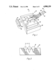
- FIG. 1 is a perspective view of apparatus which is suitable for use in performing the method of the present invention
- FIG. 2 is a partial elevational end view of the array of optical fibers
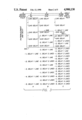
- FIG. 3 is diagram illustrating interleaved raster lines produced by an array of equally spaced elements
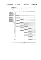
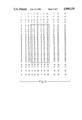
- FIG. 4 is a combined timing-location diagram showing interleaved raster lines produced by an array of five elements.
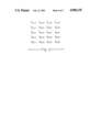
- FIGS. 5 and 6 are diagrams which illustrate the method of the present invention when used to perform two-dimensional interleaving.
- image storage medium is intended to include any medium on which an image can be formed as well as any medium which has an image formed thereon such as, for example, a photographic film, a photoconductor, or a document.
- a "set of raster lines” are traced on the image storage medium by one pass of a scanning head having multiple elements.
- Interleaving refers to the tracing of additional raster lines between raster lines traced in a previous pass, or passes, of the scanning head.
- raster refers to a completed pattern of raster lines, i. e., all of the raster lines are filled in, which provides substantially uniform coverage of an area of an image storage medium.
- Printer 10 which can be used to practice the method of the present invention.
- Printer 10 includes a scanning head in the form of a fiber optic array 12.
- Fiber optic array 12 is made up of three operative elements, each of which includes an optical fiber 14 supported on a substrate 16.
- Each optical fiber 14 is connected by means of an optical fiber connector 18 to another optical fiber 20.
- Optical fiber connector 18 can be of the type shown in commonly-assigned U.S. Pat. No. 4,723,830, entitled Optical Fiber Connectors, issued Feb. 9, 1988.
- Each of the optical fibers 20 is connected to a light source 22, such as a diode laser or a light-emitting diode.
- Each light source 22 in array 12 can be modulated according to an information signal in a well-known manner.
- Light from optical fibers 14 is focussed on a recording medium 32 by means of a lens 31.
- Both lens 31 and fiber optic array 12 are mounted on a carriage 33 which is supported for linear movement on a base 35.
- the number of operative elements in array 12 is shown as three in FIG. 1. It will be apparent, however, that the number of elements could be more or less than three.
- Recording medium 32 is supported on a drum 34 which is driven in the direction of arrow 36.
- the recording medium 32 can be, for example, photographic film.
- drum 34 As drum 34 is rotated, a set of raster lines 38 are formed on recording medium 32, and at the completion of each set of raster lines 38, carriage 33 is advanced a constant distance in the direction of arrow 40. Successive sets of raster lines 38 are traced on recording medium 32 until a desired image has been completed.
- k--an integer which is the interleaving factor that is, the number which determines the number of raster lines interleaved into a set of raster lines
- N raster lines are exposed simultaneously.
- the array is then translated a distance Nd in a direction transverse to the raster lines; and in a second pass, the next set of raster lines is written. It is also known to write rasters with spacings Y which are submultiples of d, i.e.,
- k is any integer
- the array must be translated across the recording medium a distance [N-1+(1/k)]d with respect to the recording medium to avoid exposing previously written raster lines a second time.
- the motion of an array in this process is an undesirable combination of several small steps alternating with a large step.
- the accuracy of the large steps must be the same as the accuracy of the small steps and the same as the accuracy of the spacing d of the elements in the array in order to maintain a requisite constancy of spacing of raster lines in the exposed raster pattern.
- an array of N elements can expose a raster of spacing Y which is a submultiple of the spacing d of the array elements, by translating the array a constant step size between the writing of successive sets of raster lines.
- An array step size S where
- N and k do not have any common factors other than one; in other words, this relationship holds as long as the least common multiple of N and k is Nk.
- N the number of elements in the array, should preferably be prime in order to produce the greatest variety of raster spacings, although primality of N is not a necessary condition for successful implementation of the present invention. If N and k have a common factor, interleaving of lines will produce multiple-exposure of some raster lines or skipping of other raster lines.
- FIG. 3 there is shown an implementation of a method of interleaving of raster lines using an array of equally spaced elements in which N, the number of elements, is equal to five and d is the spacing between elements.
- the raster spacing Y is equal to d/k where k is an integer.
- the first line of a raster in the image formed in columns A, B, and C is the first line in boxed areas 50A, 50B, and 50C, respectively.
- the second pass which produces the second set of raster lines, and in subsequent passes, all of the elements are actuated.
- certain of the elements will not be actuated, and the elements not actuated will be in reverse order to the nonactuated elements at the start of the image.
- elements 1 and 2 are not actuated in forming the first raster lines of the image and elements 4 and 5 would not be actuated in forming the last raster lines of the image.
- the boxed areas 50A, 50B, and 50C represent the repetitive order of elements for adjacent raster lines and the relative delays required.
- the delay D for an element n is the number of inactive passes that the element must make across the document before reaching the first line r in the raster to be exposed or read by that element, and is the largest integer satisfying the relation:
- the number of lines of delay D(n) is specific to element n for the combination of operating parameters N and k, and D(n) remains constant for that element n throughout the exposure or reading of the document.
- FIG. 4 Another illustration of the present invention is shown in FIG. 4.
- k is equal to 3
- the raster spacing Y is thus equal to d/3.
- FIG. 4 uses the same operating parameters as the arrangement shown in column C of FIG. 3.
- initiation of subsequent sets of raster lines are offset to the right, as viewed in FIG. 4, to facilitate recognition of the number of passes p by the array required for a specific element to arrive at a raster line which is exposed by that element.
- certain of the elements are inactivated during the forming of certain sets of raster lines.
- the elements which are inactivated and the order in which they are inactivated varies with the number N of elements used and with the interleaving factor k.
- a general statement of the number of elements inactivated and the order in which they are inactivated can be made for each N and k.
- An element n is inactivated on pass p of an N element array if
- FIGS. 5 and 6 diagrams are shown which illustrate the present invention when used to perform two-dimensional interleaving.
- FIG. 5 there is shown, diagrammatically, a pattern formed by individual scan areas which can be produced by an array having a matrix of N ⁇ M operative elements (not shown).
- each scan area is indicated by the number 1
- the relative location of the areas is indicated by the number in parentheses.
- the image storage medium (not shown) and the array are moved relative to each other in a first direction, and after the predetermined number of passes, the array and the storage medium are moved relative to each other in a direction transverse to the first direction.
- the predetermined number of passes is six
- the first direction is in a vertical direction
- the scan areas in the pattern can be exposures in a print mode or read areas in a read mode.
- the boxed-in area in FIG. 6 demarcates a raster in an image.
- interleaving raster lines by the method of the present invention does not require physical intervention with the array of elements, and the method can be accomplished by changes in the order of sending entire lines of data to the array elements and adjustment of the step size for translation of the array with respect to the image.
- a frame store for example, can be used.
- a frame store is an electronic storage device comprising, conceptually, a two-dimensional array of storage locations typically composed of shift registers.
- the number of storage locations in the frame store is substantially equal to the number of pixels in the visual image.
- the indices of each storage location in the frame store correspond to the spatial location of a pixel in the visual manifestation of the image.
- a common method of output scanning with a single element exposes the image in accordance with the sequence of locations in the frame store.
- This common system might be modified, for example, in either of two ways in order to implement the disclosed method of scanning interleaved raster lines with a multiple-source array.
- the data sequence sent to each element could be lengthened by an additional number of shift registers so that the output of that element would be delayed by the appropriate number of scanning passes of the multiple-source array.
- the electronic-data values for elements whose exposures must be delayed could be inserted into locations with higher line indices in the frame store to compensate for the requisite delay.
- Both the step size S of the array and the spacing d of the array elements should have the same absolute precision as the spacing desired in the final raster Y. Interleaving of lines with a constant step size of the array can be used in place of, or in addition to, tilt of the array (not shown) to generate narrowly spaced lines.
- the step size S for array translation is always equal to or less than half of the length Nd of the array, that is S ⁇ Nd/2, so that this method of interleaving avoids the large but precise steps required by the known method of filling in the raster with two different step sizes.
- Images of the array elements can be substituted for the original elements for exposure of photosensitive material.
- the disclosed method of interleaving raster lines can also be practiced in other physical systems utilizing multiple elements which do not operate upon the principle of emission of optical radiation, such as impact printing, electron-beam scanning, ion implantation, sputtering, or scratching with a stylus.
- the present invention is disclosed as being used with an output device, it will be apparent that the method could be practiced in an input scanner which is used to convert an image into an electrical signal.
- the image storage medium for storing information could be a document or photographic film, and the operative elements of the array could include photodiodes or charge-coupled devices.
Landscapes
- Engineering & Computer Science (AREA)
- Physics & Mathematics (AREA)
- Multimedia (AREA)
- Signal Processing (AREA)
- Optics & Photonics (AREA)
- General Engineering & Computer Science (AREA)
- General Physics & Mathematics (AREA)
- Theoretical Computer Science (AREA)
- Printers Or Recording Devices Using Electromagnetic And Radiation Means (AREA)
Abstract
Description
Y=d (1)
Y=d/k (2)
S=Nd/k (3)
r=Np-k(N-n) (4)
D≦k(1-n/N) (6)
D≦k(1-n/N)=3(1-3/5)=1 1/5
n≦N-Np/k (7)
Claims (11)
n≦N(1-p/k)
Priority Applications (1)
| Application Number | Priority Date | Filing Date | Title |
|---|---|---|---|
| US07/254,745 US4900130A (en) | 1988-10-07 | 1988-10-07 | Method of scanning |
Applications Claiming Priority (1)
| Application Number | Priority Date | Filing Date | Title |
|---|---|---|---|
| US07/254,745 US4900130A (en) | 1988-10-07 | 1988-10-07 | Method of scanning |
Publications (1)
| Publication Number | Publication Date |
|---|---|
| US4900130A true US4900130A (en) | 1990-02-13 |
Family
ID=22965430
Family Applications (1)
| Application Number | Title | Priority Date | Filing Date |
|---|---|---|---|
| US07/254,745 Expired - Lifetime US4900130A (en) | 1988-10-07 | 1988-10-07 | Method of scanning |
Country Status (1)
| Country | Link |
|---|---|
| US (1) | US4900130A (en) |
Cited By (31)
| Publication number | Priority date | Publication date | Assignee | Title |
|---|---|---|---|---|
| US4987450A (en) * | 1989-03-15 | 1991-01-22 | Minolta Camera Kabushiki Kaisha | Electrophotographic printer comprising aligned plural light emitting devices |
| US5015066A (en) * | 1990-05-29 | 1991-05-14 | Eastman Kodak Company | Multichannel waveguide print head with symmetric output |
| US5109476A (en) * | 1990-10-15 | 1992-04-28 | Eastman Kodak Company | Color printer with synchronous and asynchronous stages |
| US5160965A (en) * | 1989-01-30 | 1992-11-03 | Canon Kabushiki Kaisha | Image forming apparatus with small LED array |
| EP0538859A1 (en) * | 1991-10-22 | 1993-04-28 | Eastman Kodak Company | Technique for precise color-to-color registration in thermal printers |
| US5299014A (en) * | 1990-03-30 | 1994-03-29 | Rank Cintel Ltd. | Telecine method and apparatus for the production of high definition television signals |
| US5515097A (en) * | 1993-04-05 | 1996-05-07 | Eastman Kodak Company | Apparatus with beam shifting assembly means controlled to increase recording resolution |
| GB2300779A (en) * | 1995-05-12 | 1996-11-13 | Eastman Kodak Co | Interleaving thermal printing with discontiguous dye-transfer tracks on an individual multiple-source printhead pass |
| US5724086A (en) * | 1995-05-12 | 1998-03-03 | Eastman Kodak Company | Printhead having data channels with revisable addresses for interleaving scan lines |
| EP0947335A2 (en) | 1998-03-31 | 1999-10-06 | Eastman Kodak Company | Laser printer using multiple sets of lasers with multiple wavelengths |
| US6065822A (en) * | 1996-04-16 | 2000-05-23 | Eastman Kodak Company | Printer capable of producing continuous tone prints from multi-bit data signals |
| US6084626A (en) * | 1998-04-29 | 2000-07-04 | Eastman Kodak Company | Grating modulator array |
| WO2000057629A1 (en) * | 1999-03-19 | 2000-09-28 | Etec Systems, Inc. | Laser pattern generator |
| EP1040927A2 (en) | 1999-03-31 | 2000-10-04 | Eastman Kodak Company | Laser printer utilizing a spatial light modulator |
| US6181362B1 (en) | 1999-03-11 | 2001-01-30 | Creo Srl | Fault tolerant laser diode array |
| WO2001057580A2 (en) * | 2000-02-03 | 2001-08-09 | Kodak Polychrome Graphics Co. Ltd. | High power laser head system |
| EP1241013A1 (en) | 2001-03-13 | 2002-09-18 | Heidelberger Druckmaschinen Aktiengesellschaft | Imaging device for a printing plate with an array of VCSEL-light sources |
| US6597388B2 (en) | 2001-06-21 | 2003-07-22 | Kodak Polychrome Graphics, Llc | Laser-induced thermal imaging with masking |
| US6623894B2 (en) | 2001-03-14 | 2003-09-23 | Kodak Polychrome Graphics, Llc | Laser-induced thermal imaging with masking |
| US6765604B2 (en) * | 2001-02-22 | 2004-07-20 | Heidelberger Druckmaschinen Ag | Banding-reduced imaging of a printing form |
| US20040252181A1 (en) * | 2003-06-16 | 2004-12-16 | Heidelberger Druckmaschinen Ag | Imaging device for a printing form and method for arranging optical components in the imaging device |
| US6888558B2 (en) | 2001-12-19 | 2005-05-03 | Kodak Polychrome Graphics, Llc | Laser-induced thermal imaging with masking |
| US20060003262A1 (en) * | 2004-06-30 | 2006-01-05 | Eastman Kodak Company | Forming electrical conductors on a substrate |
| US20060263725A1 (en) * | 2005-05-17 | 2006-11-23 | Eastman Kodak Company | Forming a patterned metal layer using laser induced thermal transfer method |
| US20080316454A1 (en) * | 2006-02-22 | 2008-12-25 | Kleo Maschinenbau Ag | Exposure system |
| DE112007001551T5 (en) | 2006-06-30 | 2009-05-14 | Kodak Graphic Communications Canada Co., Burnaby | Method and apparatus for applying patterns of non-contiguous features |
| US20090309954A1 (en) * | 2006-06-30 | 2009-12-17 | Kodak Graphic Communications Canada Company | Methods and apparatus for selecting and applying non-contiguous features in a pattern |
| US20100128100A1 (en) * | 2007-04-26 | 2010-05-27 | Aldo Salvestro | Imaging features with a plurality of scans |
| US20120268548A1 (en) * | 2011-04-20 | 2012-10-25 | Coherent, Inc. | Laser printer with multiple laser-beam sources |
| US10399183B2 (en) | 2015-06-10 | 2019-09-03 | Ipg Photonics Corporation | Multiple beam additive manufacturing |
| WO2020023287A1 (en) | 2018-07-26 | 2020-01-30 | Eastman Kodak Company | Laser exposure head with reduced leakage |
Citations (7)
| Publication number | Priority date | Publication date | Assignee | Title |
|---|---|---|---|---|
| US4093964A (en) * | 1976-03-03 | 1978-06-06 | Crosfield Electronics Limited | Image reproducing systems |
| US4097846A (en) * | 1977-04-08 | 1978-06-27 | Energy Conversion Devices, Inc. | Data storage and retrieval system |
| US4198158A (en) * | 1978-04-14 | 1980-04-15 | Bell Telephone Laboratories, Incorporated | High resolution display |
| US4389655A (en) * | 1979-09-21 | 1983-06-21 | Siemens Aktiengesellschaft | Optical device for non-contact recording and particular facsimile reproduction of images and test |
| US4435064A (en) * | 1980-06-28 | 1984-03-06 | Ricoh Co., Ltd. | Optical exposure unit for electrophotographic printing device |
| US4566015A (en) * | 1984-06-07 | 1986-01-21 | Polaroid Corporation | Image recording apparatus with adjustable mask |
| US4723830A (en) * | 1984-06-22 | 1988-02-09 | Eastman Kodak Company | Optical fiber connectors |
-
1988
- 1988-10-07 US US07/254,745 patent/US4900130A/en not_active Expired - Lifetime
Patent Citations (7)
| Publication number | Priority date | Publication date | Assignee | Title |
|---|---|---|---|---|
| US4093964A (en) * | 1976-03-03 | 1978-06-06 | Crosfield Electronics Limited | Image reproducing systems |
| US4097846A (en) * | 1977-04-08 | 1978-06-27 | Energy Conversion Devices, Inc. | Data storage and retrieval system |
| US4198158A (en) * | 1978-04-14 | 1980-04-15 | Bell Telephone Laboratories, Incorporated | High resolution display |
| US4389655A (en) * | 1979-09-21 | 1983-06-21 | Siemens Aktiengesellschaft | Optical device for non-contact recording and particular facsimile reproduction of images and test |
| US4435064A (en) * | 1980-06-28 | 1984-03-06 | Ricoh Co., Ltd. | Optical exposure unit for electrophotographic printing device |
| US4566015A (en) * | 1984-06-07 | 1986-01-21 | Polaroid Corporation | Image recording apparatus with adjustable mask |
| US4723830A (en) * | 1984-06-22 | 1988-02-09 | Eastman Kodak Company | Optical fiber connectors |
Cited By (44)
| Publication number | Priority date | Publication date | Assignee | Title |
|---|---|---|---|---|
| US5160965A (en) * | 1989-01-30 | 1992-11-03 | Canon Kabushiki Kaisha | Image forming apparatus with small LED array |
| US4987450A (en) * | 1989-03-15 | 1991-01-22 | Minolta Camera Kabushiki Kaisha | Electrophotographic printer comprising aligned plural light emitting devices |
| US5299014A (en) * | 1990-03-30 | 1994-03-29 | Rank Cintel Ltd. | Telecine method and apparatus for the production of high definition television signals |
| US5015066A (en) * | 1990-05-29 | 1991-05-14 | Eastman Kodak Company | Multichannel waveguide print head with symmetric output |
| US5109476A (en) * | 1990-10-15 | 1992-04-28 | Eastman Kodak Company | Color printer with synchronous and asynchronous stages |
| EP0538859A1 (en) * | 1991-10-22 | 1993-04-28 | Eastman Kodak Company | Technique for precise color-to-color registration in thermal printers |
| US5515097A (en) * | 1993-04-05 | 1996-05-07 | Eastman Kodak Company | Apparatus with beam shifting assembly means controlled to increase recording resolution |
| GB2300779A (en) * | 1995-05-12 | 1996-11-13 | Eastman Kodak Co | Interleaving thermal printing with discontiguous dye-transfer tracks on an individual multiple-source printhead pass |
| US5724086A (en) * | 1995-05-12 | 1998-03-03 | Eastman Kodak Company | Printhead having data channels with revisable addresses for interleaving scan lines |
| US5808655A (en) * | 1995-05-12 | 1998-09-15 | Eastman Kodak Company | Interleaving thermal printing with discontiguous dye-transfer tracks on an individual multiple-source printhead pass |
| GB2300779B (en) * | 1995-05-12 | 2000-03-22 | Eastman Kodak Co | Interleaving thermal printing with discontiguous dye-transfer tracks on an individual multiple source printhead pass |
| US6065822A (en) * | 1996-04-16 | 2000-05-23 | Eastman Kodak Company | Printer capable of producing continuous tone prints from multi-bit data signals |
| US6064417A (en) * | 1998-03-31 | 2000-05-16 | Eastman Kodak Company | Laser printer using multiple sets of lasers with multiple wavelengths |
| EP0947335A2 (en) | 1998-03-31 | 1999-10-06 | Eastman Kodak Company | Laser printer using multiple sets of lasers with multiple wavelengths |
| US6084626A (en) * | 1998-04-29 | 2000-07-04 | Eastman Kodak Company | Grating modulator array |
| US6181362B1 (en) | 1999-03-11 | 2001-01-30 | Creo Srl | Fault tolerant laser diode array |
| WO2000057629A1 (en) * | 1999-03-19 | 2000-09-28 | Etec Systems, Inc. | Laser pattern generator |
| EP1040927A2 (en) | 1999-03-31 | 2000-10-04 | Eastman Kodak Company | Laser printer utilizing a spatial light modulator |
| US6169565B1 (en) | 1999-03-31 | 2001-01-02 | Eastman Kodak Company | Laser printer utilizing a spatial light modulator |
| WO2001057580A2 (en) * | 2000-02-03 | 2001-08-09 | Kodak Polychrome Graphics Co. Ltd. | High power laser head system |
| WO2001057580A3 (en) * | 2000-02-03 | 2002-04-04 | Kodak Polychrome Graphics Co | High power laser head system |
| US6765604B2 (en) * | 2001-02-22 | 2004-07-20 | Heidelberger Druckmaschinen Ag | Banding-reduced imaging of a printing form |
| EP1241013A1 (en) | 2001-03-13 | 2002-09-18 | Heidelberger Druckmaschinen Aktiengesellschaft | Imaging device for a printing plate with an array of VCSEL-light sources |
| US6798438B2 (en) | 2001-03-13 | 2004-09-28 | Heidelberger Druckmaschinen Ag | Image-recording device for a printing form, having an array of VCSEL light sources |
| US6943816B2 (en) | 2001-03-14 | 2005-09-13 | Kodak Polychrome Graphics Llc | Laser-induced thermal imaging with masking |
| US6623894B2 (en) | 2001-03-14 | 2003-09-23 | Kodak Polychrome Graphics, Llc | Laser-induced thermal imaging with masking |
| US20040027448A1 (en) * | 2001-03-14 | 2004-02-12 | Kodak Polychrome Graphics | Laser-induced thermal imaging with masking |
| US6597388B2 (en) | 2001-06-21 | 2003-07-22 | Kodak Polychrome Graphics, Llc | Laser-induced thermal imaging with masking |
| US6888558B2 (en) | 2001-12-19 | 2005-05-03 | Kodak Polychrome Graphics, Llc | Laser-induced thermal imaging with masking |
| US7317470B2 (en) * | 2003-06-16 | 2008-01-08 | Heidelberger Druckmaschinen Ag | Imaging device for a printing form and method for arranging optical components in the imaging device |
| US20040252181A1 (en) * | 2003-06-16 | 2004-12-16 | Heidelberger Druckmaschinen Ag | Imaging device for a printing form and method for arranging optical components in the imaging device |
| US20060003262A1 (en) * | 2004-06-30 | 2006-01-05 | Eastman Kodak Company | Forming electrical conductors on a substrate |
| US7648741B2 (en) | 2005-05-17 | 2010-01-19 | Eastman Kodak Company | Forming a patterned metal layer using laser induced thermal transfer method |
| US20060263725A1 (en) * | 2005-05-17 | 2006-11-23 | Eastman Kodak Company | Forming a patterned metal layer using laser induced thermal transfer method |
| US20080316454A1 (en) * | 2006-02-22 | 2008-12-25 | Kleo Maschinenbau Ag | Exposure system |
| US8248581B2 (en) * | 2006-02-22 | 2012-08-21 | Kleo Ag | Exposure system |
| DE112007001551T5 (en) | 2006-06-30 | 2009-05-14 | Kodak Graphic Communications Canada Co., Burnaby | Method and apparatus for applying patterns of non-contiguous features |
| US20090309954A1 (en) * | 2006-06-30 | 2009-12-17 | Kodak Graphic Communications Canada Company | Methods and apparatus for selecting and applying non-contiguous features in a pattern |
| US20100128100A1 (en) * | 2007-04-26 | 2010-05-27 | Aldo Salvestro | Imaging features with a plurality of scans |
| US20120268548A1 (en) * | 2011-04-20 | 2012-10-25 | Coherent, Inc. | Laser printer with multiple laser-beam sources |
| US8558859B2 (en) * | 2011-04-20 | 2013-10-15 | Coherent, Inc. | Laser printer with multiple laser-beam sources |
| US10399183B2 (en) | 2015-06-10 | 2019-09-03 | Ipg Photonics Corporation | Multiple beam additive manufacturing |
| WO2020023287A1 (en) | 2018-07-26 | 2020-01-30 | Eastman Kodak Company | Laser exposure head with reduced leakage |
| US10761399B2 (en) | 2018-07-26 | 2020-09-01 | Eastman Kodak Company | Laser exposure head with reduced leakage |
Similar Documents
| Publication | Publication Date | Title |
|---|---|---|
| US4900130A (en) | Method of scanning | |
| EP0620676B1 (en) | Process for digital micromirror printer | |
| US3742129A (en) | Apparatus and method for generating halftones for image reproduction | |
| EP0088555B1 (en) | Dot matrix printing method and printer therefor | |
| US6784912B2 (en) | Compact multibeam laser light source and interleaving raster scan line method for exposing printing plates | |
| US4135212A (en) | Printing methods and apparatus | |
| US4344677A (en) | Laser printer with multiple scanning beams | |
| EP0783223A2 (en) | Method and apparatus for interleaving raster scan lines in a multi-beam laser imaging device | |
| EP0375429B1 (en) | Digital printers | |
| US4819018A (en) | High-speed broad-brush laser photocomposition | |
| GB2043392A (en) | Half-tone facsimile reproduction | |
| KR100305290B1 (en) | Printing plate exposure apparatus using image modification | |
| US5274394A (en) | Electronic adjustment of slow scan image registration in an image recording apparatus | |
| US4905025A (en) | Method of and apparatus for recording image on photosensitive material with a plurality of photobeams | |
| US7190435B2 (en) | Pattern writing apparatus and pattern writing method | |
| US4975728A (en) | Flying spot scanner-printer | |
| US3273476A (en) | Photocomposing system | |
| KR20080059415A (en) | Plotting device and image data creation method | |
| JP3246754B2 (en) | Optical recording device and information processing system | |
| JP3179680B2 (en) | Image recording device | |
| US4265509A (en) | High speed holographic optical printing system | |
| JPH0537750A (en) | Laser recording device | |
| EP2334498B1 (en) | Improvements in semiconductor lasers | |
| US5548408A (en) | Image processing system | |
| JPH07111508B2 (en) | Laser exposure method for image scanning recording apparatus |
Legal Events
| Date | Code | Title | Description |
|---|---|---|---|
| AS | Assignment |
Owner name: EASTMAN KODAK COMPANY, ROCHESTER, NEW YORK, A NEW Free format text: ASSIGNMENT OF ASSIGNORS INTEREST.;ASSIGNOR:HAAS, DANIEL D.;REEL/FRAME:004970/0127 Effective date: 19880926 Owner name: EASTMAN KODAK COMPANY, NEW YORK Free format text: ASSIGNMENT OF ASSIGNORS INTEREST;ASSIGNOR:HAAS, DANIEL D.;REEL/FRAME:004970/0127 Effective date: 19880926 |
|
| FEPP | Fee payment procedure |
Free format text: PAYOR NUMBER ASSIGNED (ORIGINAL EVENT CODE: ASPN); ENTITY STATUS OF PATENT OWNER: LARGE ENTITY |
|
| STCF | Information on status: patent grant |
Free format text: PATENTED CASE |
|
| CC | Certificate of correction | ||
| FPAY | Fee payment |
Year of fee payment: 4 |
|
| FEPP | Fee payment procedure |
Free format text: PAYER NUMBER DE-ASSIGNED (ORIGINAL EVENT CODE: RMPN); ENTITY STATUS OF PATENT OWNER: LARGE ENTITY Free format text: PAYOR NUMBER ASSIGNED (ORIGINAL EVENT CODE: ASPN); ENTITY STATUS OF PATENT OWNER: LARGE ENTITY |
|
| FPAY | Fee payment |
Year of fee payment: 8 |
|
| FPAY | Fee payment |
Year of fee payment: 12 |