US4899807A - Engine coolant flush-filtering using external gas pressure and blocked radiator fill port - Google Patents

Engine coolant flush-filtering using external gas pressure and blocked radiator fill port Download PDF

Info

Publication number
US4899807A
US4899807A US07/248,172 US24817288A US4899807A US 4899807 A US4899807 A US 4899807A US 24817288 A US24817288 A US 24817288A US 4899807 A US4899807 A US 4899807A
Authority
US
United States
Prior art keywords
coolant
cooling system
radiator
coolant liquid
liquid
Prior art date
Legal status (The legal status is an assumption and is not a legal conclusion. Google has not performed a legal analysis and makes no representation as to the accuracy of the status listed.)
Expired - Fee Related
Application number
US07/248,172
Inventor
Marcel Vataru
James L. Baylor
Current Assignee (The listed assignees may be inaccurate. Google has not performed a legal analysis and makes no representation or warranty as to the accuracy of the list.)
Illinois Tool Works Inc
Original Assignee
Wynn Oil Co
Priority date (The priority date is an assumption and is not a legal conclusion. Google has not performed a legal analysis and makes no representation as to the accuracy of the date listed.)
Filing date
Publication date
Priority claimed from US07/087,696 external-priority patent/US4793403A/en
Assigned to WYNN OIL COMPANY, 2600 EAST NUTWOOD AVE., FULLERTON, CA 92631, A CORP. OF CA. reassignment WYNN OIL COMPANY, 2600 EAST NUTWOOD AVE., FULLERTON, CA 92631, A CORP. OF CA. ASSIGNMENT OF ASSIGNORS INTEREST. Assignors: BAYLOR, JAMES L., VATARU, MARCEL
Priority to US07/248,172 priority Critical patent/US4899807A/en
Application filed by Wynn Oil Co filed Critical Wynn Oil Co
Priority to EP89116208A priority patent/EP0360057A3/en
Priority to NZ23061889A priority patent/NZ230618A/en
Priority to MX1759089A priority patent/MX164369B/en
Priority to AU41716/89A priority patent/AU626217B2/en
Priority to JP24784789A priority patent/JPH02185616A/en
Publication of US4899807A publication Critical patent/US4899807A/en
Application granted granted Critical
Priority to US07/535,049 priority patent/US5078866A/en
Assigned to ILLINOIS TOOL WORKS INC. reassignment ILLINOIS TOOL WORKS INC. ASSIGNMENT OF ASSIGNORS INTEREST (SEE DOCUMENT FOR DETAILS). Assignors: WYNN OIL COMPANY
Anticipated expiration legal-status Critical
Expired - Fee Related legal-status Critical Current

Links

Images

Classifications

    • FMECHANICAL ENGINEERING; LIGHTING; HEATING; WEAPONS; BLASTING
    • F01MACHINES OR ENGINES IN GENERAL; ENGINE PLANTS IN GENERAL; STEAM ENGINES
    • F01PCOOLING OF MACHINES OR ENGINES IN GENERAL; COOLING OF INTERNAL-COMBUSTION ENGINES
    • F01P11/00Component parts, details, or accessories not provided for in, or of interest apart from, groups F01P1/00 - F01P9/00
    • F01P11/06Cleaning; Combating corrosion
    • F01P2011/065Flushing

Definitions

  • This invention relates generally to cleaning of an internal combustion engine cooling system, more particularly to treatment of used coolant exteriorly of such a system for subsequent return to the system.
  • the method of the invention embodies the steps:
  • said forcing step including supplying a pressurized gas to the cooling system to drive coolant liquid therefrom,
  • the cooling system including a heat radiator including a container having a coolant liquid fill opening
  • said forcing step including employing said gas to drive coolant liquid from the radiator via said container fill opening
  • Another objective is to provide a siphoning probe insertible into the radiator associated with the engine to provide a path for coolant to exit the radiator from its lower interior, for external treatment.
  • the probe is associated with a closure for the radiator fill port, to keep that port closed during performance of the steps a)-f) referred to, preventing ejection of hot fluid which could harm the operator.
  • Additional steps include filtering contaminant particulate from the coolant as it flows to the external treatment zone; adding fresh chemicals to the radiator after completion of service; employing gas pressure to drive the coolant from the holding zone back to the coolant system at the engine, and filtering the returning coolant.
  • a further objective is to employ the driving gas pressure to test the coolant system for any leakage.
  • FIG. 1 is a schematic view of apparatus employing the invention
  • FIG. 2 is an enlarged section showing details of a radiator fill port closure at a by-pass valve
  • FIG. 3 is a front view of a control console.
  • FIG. 1 there is schematically shown an internal combustion engine 10 having a block 11 defining coolant passages through which liquid coolant (such as water, and anti-freeze additive including polyethylene glycol, etc.) is adapted to pass; a radiator 12; and a coolant pump 13 connected to pump coolant between the block and radiator, as via lines or ducts 14 and 14a. Also shown is a heater 15 connected at 17 with the block, as for use in a vehicle to be heated. From the heater, coolant may pass at 18 to the engine block 11. During continued operation of the engine, the coolant tends to become contaminated with particulate such as rust particles and precipitate (calcium salts, etc.), and the additive degenerates. In the past, the coolant was drained from the system as to sewer lines, and the system flushed with liquid which was also drained. The present invention eliminates such environmentally objectionable draining, and also protects the operator.
  • liquid coolant such as water, and anti-freeze additive including polyethylene glycol, etc.
  • apparatus generally designated at 20 is provided, and comprises:
  • the method and apparatus makes possible the re-use of the coolant by withdrawing it from the coolant system, treating it externally of that system, and re-circulating the rejuvenated coolant back into the system so as to avoid need for disposal of the coolant as by drainage to the environment.
  • the first means for forcing the liquid coolant from the coolant system may advantageously include an elongated tube or tubular probe 21 insertible endwise into the outer container or shell 22 incorporated by the radiator, and via the usual fill opening 23a of that shell to extract coolant from the lower interior or extent of the radiator, for passage from the radiator as via duct 23.
  • Means 24 associated with, and typically carried by that tubular probe 21, is provided for maintaining the fill opening otherwise closed during removal of coolant from the radiator.
  • Such means may comprise a screw-on cap 24 which is annular to pass the elongated tube 21.
  • Cap is screwed onto the neck 25 of the radiator fill-opening, the probe then reaching or extending to the bottom interior of the radiator so that substantially all liquid may be removed, extracted or siphoned from the radiator, to the line 23.
  • liquid in the heater and block flows to the radiator for such removal, and typically under pressure within the radiator so as to flow up the tubular probe to the external line 23 and then to a treatment zone.
  • FIG. 2 shows cap details.
  • the second means for treating the removed coolant may advantageously comprise a liquid receiver, such as for example a holding tank 27 to which liquid flows via line 23, filter 28 connected in series with that line, and valve 29 in the line. Particulate and congealed substances in the flowing liquid are removed by the filter 28, which may be replaced at intervals; the used-up filter then being disposed of in accordance with environmentally acceptably safe procedures.
  • the normally aqueous liquid received into the holding tank interior zone 31, as via inlet 30 may then be treated, as by addition of chemical agent or agents introduced via port 32.
  • chemicals may include corrosion inhibitor i.e. anti-rust compound, pH adjustment chemicals, and fresh anti-freeze compound (glycol, for example). If any sludge develops in tank 27 after prolonged use, it may be removed to a container 34 and disposed of, environmentally safely. See line 35 and valve 36.
  • the third means for returning the treated coolant to the engine cooling system includes a line or duct 37 extending from tank 27 to a connection 38 with the cooling system.
  • Connection 38 is advantageously located in the line 17 from the block 11 to the heater.
  • a clamp 39 may be located on or at that line for stopping liquid passing from 38 to the block, via line 17.
  • a control valve 40 and a filter 41 are connected in series with line 37, valve 40 being opened when return of coolant to the system is desired. Filter 41 removes any further contaminant.
  • An important feature of the invention is the provision, in association with the first means referred to above, of a pressurized gas (as for example air pressure) source 43 connectible via a main valve 44 in duct 45 and a control valve 46, connected via duct 47 with the coolant systems for forcing coolant from that system and to tank 27 (as via the probe 21 and line 23).
  • Line 47 may be connected to duct 17, at 48, as shown.
  • Air pressure then drives coolant from the heater to the radiator, as via line 18, and the pump 13, coolant also flowing from the block to the radiator lower interior extent 12a, for pick-up by the probe 21.
  • Valve 46 is advantageously a three-way valve, and is thus controllable to alternatively supply air under pressure via line 52 to the holding tank interior for application to treated liquid 31 in the tank for return supply under pressure to the engine cooling system, along the flow path described above.
  • the engine Prior to initial operation of the system, the engine is operated to heat the coolant in the system, and as a result a thermostat controlled valve in that system, indicated at 60, is opened when the coolant reaches a predetermined temperature. Rust loosening or cleaning chemical additive (such as detergent solution) may be initially added to the coolant in the radiator to circulate during warm-up. The probe 21 is then inserted in the radiator, and operation of the apparatus is begun. Note that the apparatus is quickly connectible to the cooling system, as via hoses or lines 23, 37 and 47.
  • Rust loosening or cleaning chemical additive such as detergent solution
  • a pressure gauge 63 is connected to air line 45 to indicate the pressure in that line.
  • the radiator fill opening 23a is closed as by returning the radiator cap to neck 25, and tightening it to seal the opening 23a.
  • air pressure from supply 43 pressurizes the entire coolant system, and gauge 63 is observed to note the pressure.
  • Air pressure regulator 45a in line 45 regulates the pressure to a safe level.
  • Valve 44 is then closed, and the gauge 63 is again observed to note any relatively rapid fall-off of pressure. If that does not occur, the pressure test indicates a non-leaking system; however, if the pressure falls-off, the test indicates that a leak has developed in the coolant system, and should be attended to. For example, a STOP-LEAK solution may be added to the contents of the radiator in an effort to arrest the pressure leak.
  • the modified cap 24a has a domed wall 90 with a central through opening 91 to pass tubular probe 21.
  • a seal 92 carried by the cap seals off against the outer surface of the probe (which may be plastic) when threaded fitting 150 is tightened in threaded bore 151.
  • the probe is axially shiftable, endwise, relative to opening 91, when fitting 150 is loosened.
  • the cap has a lower lip 93 that tightens on the annular lip 94 of the radiator container, as shown, at which time an annular extension 152 fits in radiator bore 153, sealing at 154.
  • An off-set through port 95 has a by-pass duct 96 connected therewith at 97, and a manually controllable by-pass valve 98 in duct 96 controls escape of pressurized fluid from the radiator upper interior 12b, and to an over-flow tank 100.
  • By-pass valve 98 is opened as during air pressure induced return of treated coolant fluid to the system, that fluid allowed to rise in the radiator, to level 101, above indicator core 104. Any excess fluid (air or coolant or both) rising in the radiator exits via the by-pass duct and valve 98, to tank 100.
  • Duct 96 is transparent so that any loss of coolant can be visually monitored. Coolant collected in tank 100 can be returned to tank 27, as by siphoning. See siphon 106.
  • the radiator container or shell appears at 109.
  • connection 48 Open valve 44 and adjust valve 46 to direct air pressure to connection 48, which causes air pressure to drive coolant from the system to holding tank 27, via probe 21, filter 28, and valve 29, which is OPEN;
  • connections to line 17 may take the form of those described in U.S. Pat. No. 4,109,703, FIG. 12.
  • FIG. 3 shows valve controls on a console panel 105, along with gauge 63.

Abstract

A method for rapid and efficient cleaning of an internal combustion engine cooling system includes:
(a) forcing the coolant liquid from the cooling system to the exterior of that system,
(b) treating the coolant liquid from the cooling system to the exterior of that system,
(b) treating the coolant liquid in a zone or zones outside the cooling system, such treating including removing contaminant from the coolant liquid,
(c) returning the treated coolant liquid to the cooling system,
(d) the forcing step including supplying pressurized gas to the cooling system to drive coolant liquid therefrom,
(e) the cooling system including a heat radiator including a container having a coolant liquid fill opening, and the forcing step including employing the gas to drive coolant liquid from the radiator via the container fill opening,
(f) and including the step of controllably venting fluid including gas from the container via the fill opening, during the step of returning the treated coolant liquid to the cooling system.

Description

This application is a continuation-in-part of Serial No. 087,696 filed Aug. 20, 1987, now U.S. Pat. No. 4,793,403.
BACKGROUND OF THE INVENTION
This invention relates generally to cleaning of an internal combustion engine cooling system, more particularly to treatment of used coolant exteriorly of such a system for subsequent return to the system.
Studies show that over-heating is a major cause of vehicle breakdowns on highways. Engine cooling systems must operate efficiently at all times to avoid costly repairs that result from excessive temperature. In this regard, cooling systems contaminated by rust, scale build-up and sludge cannot provide adequate heat transfer and cooling system efficiency; in addition, thermostats fail to open, hoses deteriorate, impellers bind or break-off, and engine blocks can become distorted or crack. Accordingly, there is a need for efficient engine cooling system flushing methods and apparatus; however, flushing of such systems in the past required draining of the removed liquid to sewer or waste lines, which was environmentally objectionable. Accordingly, need has developed for apparatus and method to clean engine coolant systems without such drainage. No way was known for accomplishing this objective in the unusually advantageous manner as is now provided by this invention.
SUMMARY OF THE INVENTION
It is a major object of the invention to provide procedures and apparatus characterized as overcoming the above objections and as meeting the above needs, whereby rapid and efficient cleaning of the engine coolant system may be accomplished in an environmentally non-objectionable manner.
Basically, the method of the invention embodies the steps:
a) forcing the liquid coolant from the cooling system to the exterior of that system,
b) treating the coolant liquid in a zone or zones outside the cooling system, said treating including removing contaminant from the coolant liquid,
c) returning the treated coolant liquid to the cooling system,
d) said forcing step including supplying a pressurized gas to the cooling system to drive coolant liquid therefrom,
e) the cooling system including a heat radiator including a container having a coolant liquid fill opening, and said forcing step including employing said gas to drive coolant liquid from the radiator via said container fill opening,
f) and including the step of controllably venting fluid including gas from said contained via said fill opening, during said step of returning the treated coolant liquid to the cooling system.
It is another objective of the invention to supply a pressurized gas such as air to the cooling system in such a way as to drive coolant therefrom, for external treatment as in a holding tank zone.
Another objective is to provide a siphoning probe insertible into the radiator associated with the engine to provide a path for coolant to exit the radiator from its lower interior, for external treatment. The probe is associated with a closure for the radiator fill port, to keep that port closed during performance of the steps a)-f) referred to, preventing ejection of hot fluid which could harm the operator.
Additional steps include filtering contaminant particulate from the coolant as it flows to the external treatment zone; adding fresh chemicals to the radiator after completion of service; employing gas pressure to drive the coolant from the holding zone back to the coolant system at the engine, and filtering the returning coolant.
A further objective is to employ the driving gas pressure to test the coolant system for any leakage.
These and other objects and advantages of the invention, as well as the details of an illustrative embodiment, will be more fully understood from the following specification and drawings, in which;
DRAWING DESCRIPTION
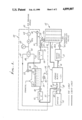
FIG. 1 is a schematic view of apparatus employing the invention;
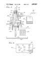
FIG. 2 is an enlarged section showing details of a radiator fill port closure at a by-pass valve; and
FIG. 3 is a front view of a control console.
DETAILED DESCRIPTION
In FIG. 1, there is schematically shown an internal combustion engine 10 having a block 11 defining coolant passages through which liquid coolant (such as water, and anti-freeze additive including polyethylene glycol, etc.) is adapted to pass; a radiator 12; and a coolant pump 13 connected to pump coolant between the block and radiator, as via lines or ducts 14 and 14a. Also shown is a heater 15 connected at 17 with the block, as for use in a vehicle to be heated. From the heater, coolant may pass at 18 to the engine block 11. During continued operation of the engine, the coolant tends to become contaminated with particulate such as rust particles and precipitate (calcium salts, etc.), and the additive degenerates. In the past, the coolant was drained from the system as to sewer lines, and the system flushed with liquid which was also drained. The present invention eliminates such environmentally objectionable draining, and also protects the operator.
In accordance with the invention, apparatus generally designated at 20 is provided, and comprises:
a) first means for forcing the coolant liquid from the cooling system to the exterior of that system,
b) second means in communication with said first means for receiving the coolant liquid at the exterior of the cooling system, for treatment thereof, and
c) third means in communication with said second means for returning the treated coolant liquid to the cooling system.
While specific means are shown within the overall block 20, it will be understood that other, or equivalent means are usable to perform the following steps:
a) forcing the liquid coolant from the cooling system to the exterior of that system,
b) treating the coolant liquid in a zone or zones outside the cooling system, said treating including removing contaminant from the coolant liquid, and
c) returning the treated coolant liquid to the cooling system.
In this regard, it will be noted that the method and apparatus makes possible the re-use of the coolant by withdrawing it from the coolant system, treating it externally of that system, and re-circulating the rejuvenated coolant back into the system so as to avoid need for disposal of the coolant as by drainage to the environment.
The specific means illustrated incorporates multiple and unusual advantages in terms of simplicity, effectiveness and rapidity of employment and operation; for example, the first means for forcing the liquid coolant from the coolant system may advantageously include an elongated tube or tubular probe 21 insertible endwise into the outer container or shell 22 incorporated by the radiator, and via the usual fill opening 23a of that shell to extract coolant from the lower interior or extent of the radiator, for passage from the radiator as via duct 23. Means 24 associated with, and typically carried by that tubular probe 21, is provided for maintaining the fill opening otherwise closed during removal of coolant from the radiator. Such means may comprise a screw-on cap 24 which is annular to pass the elongated tube 21. Cap is screwed onto the neck 25 of the radiator fill-opening, the probe then reaching or extending to the bottom interior of the radiator so that substantially all liquid may be removed, extracted or siphoned from the radiator, to the line 23. As will appear, liquid in the heater and block flows to the radiator for such removal, and typically under pressure within the radiator so as to flow up the tubular probe to the external line 23 and then to a treatment zone. FIG. 2 shows cap details.
The second means for treating the removed coolant may advantageously comprise a liquid receiver, such as for example a holding tank 27 to which liquid flows via line 23, filter 28 connected in series with that line, and valve 29 in the line. Particulate and congealed substances in the flowing liquid are removed by the filter 28, which may be replaced at intervals; the used-up filter then being disposed of in accordance with environmentally acceptably safe procedures. The normally aqueous liquid received into the holding tank interior zone 31, as via inlet 30 may then be treated, as by addition of chemical agent or agents introduced via port 32. Such chemicals may include corrosion inhibitor i.e. anti-rust compound, pH adjustment chemicals, and fresh anti-freeze compound (glycol, for example). If any sludge develops in tank 27 after prolonged use, it may be removed to a container 34 and disposed of, environmentally safely. See line 35 and valve 36.
The third means for returning the treated coolant to the engine cooling system includes a line or duct 37 extending from tank 27 to a connection 38 with the cooling system. Connection 38 is advantageously located in the line 17 from the block 11 to the heater. A clamp 39 may be located on or at that line for stopping liquid passing from 38 to the block, via line 17. A control valve 40 and a filter 41 are connected in series with line 37, valve 40 being opened when return of coolant to the system is desired. Filter 41 removes any further contaminant.
An important feature of the invention is the provision, in association with the first means referred to above, of a pressurized gas (as for example air pressure) source 43 connectible via a main valve 44 in duct 45 and a control valve 46, connected via duct 47 with the coolant systems for forcing coolant from that system and to tank 27 (as via the probe 21 and line 23). Line 47 may be connected to duct 17, at 48, as shown. Air pressure then drives coolant from the heater to the radiator, as via line 18, and the pump 13, coolant also flowing from the block to the radiator lower interior extent 12a, for pick-up by the probe 21.
Valve 46 is advantageously a three-way valve, and is thus controllable to alternatively supply air under pressure via line 52 to the holding tank interior for application to treated liquid 31 in the tank for return supply under pressure to the engine cooling system, along the flow path described above.
Prior to initial operation of the system, the engine is operated to heat the coolant in the system, and as a result a thermostat controlled valve in that system, indicated at 60, is opened when the coolant reaches a predetermined temperature. Rust loosening or cleaning chemical additive (such as detergent solution) may be initially added to the coolant in the radiator to circulate during warm-up. The probe 21 is then inserted in the radiator, and operation of the apparatus is begun. Note that the apparatus is quickly connectible to the cooling system, as via hoses or lines 23, 37 and 47.
Finally, a pressure gauge 63 is connected to air line 45 to indicate the pressure in that line. After air pressure has returned the treated coolant to the system, the radiator fill opening 23a is closed as by returning the radiator cap to neck 25, and tightening it to seal the opening 23a. Thereafter air pressure from supply 43 pressurizes the entire coolant system, and gauge 63 is observed to note the pressure. Air pressure regulator 45a in line 45 regulates the pressure to a safe level. Valve 44 is then closed, and the gauge 63 is again observed to note any relatively rapid fall-off of pressure. If that does not occur, the pressure test indicates a non-leaking system; however, if the pressure falls-off, the test indicates that a leak has developed in the coolant system, and should be attended to. For example, a STOP-LEAK solution may be added to the contents of the radiator in an effort to arrest the pressure leak.
In FIG. 2, the modified cap 24a has a domed wall 90 with a central through opening 91 to pass tubular probe 21. A seal 92 carried by the cap seals off against the outer surface of the probe (which may be plastic) when threaded fitting 150 is tightened in threaded bore 151. The probe is axially shiftable, endwise, relative to opening 91, when fitting 150 is loosened. The cap has a lower lip 93 that tightens on the annular lip 94 of the radiator container, as shown, at which time an annular extension 152 fits in radiator bore 153, sealing at 154. An off-set through port 95 has a by-pass duct 96 connected therewith at 97, and a manually controllable by-pass valve 98 in duct 96 controls escape of pressurized fluid from the radiator upper interior 12b, and to an over-flow tank 100. By-pass valve 98 is opened as during air pressure induced return of treated coolant fluid to the system, that fluid allowed to rise in the radiator, to level 101, above indicator core 104. Any excess fluid (air or coolant or both) rising in the radiator exits via the by-pass duct and valve 98, to tank 100. Thus, hot fluid under pressure cannot discharge in direction 102, outside probe 21, since the radiator fill port 23a is closed by cap or closure 24a. Duct 96 is transparent so that any loss of coolant can be visually monitored. Coolant collected in tank 100 can be returned to tank 27, as by siphoning. See siphon 106. The radiator container or shell appears at 109.
SUMMARY OF OPERATION
The following is a summary of steps that may be carried out during performance of the method of the invention:
1) Add cleaning or flushing chemicals to engine coolant system after preliminary testing the system for leaks;
2) Connect apparatus 20 to the cooling system as shown in FIG. 1, and as described above;
3) Operate engine for about ten minutes to circulate the chemicals for loosening dirt, rust, sludge, etc., and also to warm up coolant solution so that thermostat controlled valve 60 opens, at about 190°205° F.;
4) Insert probe 26 into radiator and tighten its cap means 24a to the lip 94;
5) Open valve 44 and adjust valve 46 to direct air pressure to connection 48, which causes air pressure to drive coolant from the system to holding tank 27, via probe 21, filter 28, and valve 29, which is OPEN;
6) Close valve 44;
7) Leave probe 21 in the radiator, and leave fill-opening 23a closed by cap 24a. Open by-pass valve 98;
8) Open valve 44 and adjust valve 46 to direct air pressure to tank 27, via line 52. Inlet 32 should be closed. This drives coolant from the tank, through filter 41, and to the coolant system at line 17. Excess air or fluid vents via valve 98;
9) When all coolant has been returned to the system (as can be viewed via line 37 which is transparent), the by-pass valve 98 is closed;
10) Pressurize the coolant system, and close valve 44;
11) Observe gauge 63 for any pressure leaks;
12) Relieve pressure in the system as by slowly opening the overflow valve attached to the cap at the radiator neck 25;
13) Disconnect the hoses or lines from the line 17; and replace the standard radiator cap to neck 25, after withdrawing probe 21.
The connections to line 17 may take the form of those described in U.S. Pat. No. 4,109,703, FIG. 12.
FIG. 3 shows valve controls on a console panel 105, along with gauge 63. A flow indicator (spinner) connected into line 17, is shown at 106.

Claims (31)

We claim:
1. For use with an internal combustion engine cooling system, the combination comprising:
a) first means for forcing the coolant liquid from the cooling system to the exterior of that system,
b) second means in communication with said first means for receiving the coolant liquid at the exterior of the cooling system, for treatment thereof, and
c) third means in communication with said second means for returning the treated coolant liquid to the cooling system,
d) the cooling system including a heat radiator including a container having a coolant liquid fill opening, and said first means includes an elongated tube insertible into the container via said fill opening to extract coolant liquid from the lower extent of the radiator for passage from the radiator, and means associated with the tube for maintaining the fill opening otherwise closed during said passage of coolant from the radiator,
e) said last named means comprising a closure having a through opening in communication with said elongated tube, the closure attachable to the container proximate the fill opening, said closure having a bypass opening to pass pressurized fluid from the container interior outside the tube and proximate the fill opening, and including a means for controllably venting said pressurized fluid via bypass opening.
2. The combination of claim 1 including an overflow tank outside the container, and ducting extending from said by-pass opening to said overflow tank.
3. The combination of claim 1 wherein said means for controllably venting said pressurized fluid compresses a manually operable shut-off valve associated with said by-pass opening.
4. The combination of claim 3 wherein said shut-off valve is mounted on the closure.
5. The combination of claim 4 wherein said closure is a metallic cap which has a dome shaped wall defining said through opening at the center of said wall, the by-pass opening located in said wall, in off-set relation to said through opening.
6. The combination of claim 1 wherein said elongated tube extends through said through opening.
7. The combination of claim 5 wherein said elongated tube is a plastic tube that extends through said through opening and there being means carried by the cap for sealing off about the elongated plastic tube.
8. The combination of claim 1 wherein said second means includes a holding tank for collecting said coolant liquid in a holding zone.
9. The combination of claim 8 wherein said second means includes a filter connected to pass coolant liquid flowing to said holding zone.
10. The combination of claim 8 wherein said third means includes a filter connected to pass coolant liquid being returned from the holding zone to the cooling system.
11. The combination of claim 8 wherein the cooling system includes cooling passages in an engine block and in a heater, there being a coolant flow connection passage between said coolant passages in the block and heater, and wherein said third means includes a coolant return flow duct in communication with said flow connection passage.
12. The combination of claim 11 wherein said first means includes a valve and ducting, and a pressurized gas source connectible via said valve and ducting with said flow connection passage.
13. The combination of claim 8 wherein said third means includes a valve and ducting in communication with said holding tank, and a pressurized gas source connectible via said valve and ducting with said tank for driving liquid from the tank to return the liquid to the cooling system.
14. The combination of claim 13 wherein the cooling system includes cooling passages in an engine block and in a heater, there being a coolant flow connection passage between said coolant passages in the block and heater, and wherein said third means includes a coolant return flow duct in communication with said flow connection passage.
15. The combination of claim 1 wherein said third means includes a source of pressurized gas connected to drive treated coolant back into the coolant system at a location spaced from the radiator, spent gas leaving the system via said by-pass opening.
16. The combination of claim 15 wherein the spent gas consists of air.
17. In the method of treating coolant liquid in an internal combustion engine cooling system, the steps that include:
a) forcing the coolant liquid from the cooling system to the exterior of that system,
b) treating the coolant liquid in a zone or zones outside the cooling system, said treating including removing contaminant from the coolant liquid, and
c) returning the treated coolant liquid to the cooling system,
d) said forcing step includes supplying a pressurized gas to the cooling system to drive coolant liquid therefrom,
e) the cooling system including a heat radiator including a container having a coolant liquid fill opening, and said forcing step including employing said gas to drive coolant liquid from the radiator via said container fill opening,
f) and including the step of controllably venting fluid including gas from said container via a closure at said fill opening, during said step of returning the treated coolant liquid to the cooling system.
18. The method of claim 17 including providing an elongated tube and inserting the tube into the radiator via said fill opening to extract said coolant liquid from the lower extent of the radiator for said passage from the radiator, and maintaining said fill opening otherwise closed during said passage of coolant liquid from the radiator.
19. The method of claim 18 wherein an overflow tank is provided in association with the radiator, and including discharging into said tank fluid vented via said by-pass valve, and controlling said valve to control said venting.
20. The method of claim 19 wherein an overflow tank is provided in association with the radiator, and including discharging into said tank fluid vented via said by-pass valve, and controlling said valve to control said venting.
21. The method of claim 17 wherein said treating step includes filtering contaminant particles from the cooling liquid.
22. The method of claim 17 wherein said treating step includes collecting said coolant liquid in a holding zone, and adding chemical agent or agents to the collected liquid in the holding zone.
23. The method of claim 22 wherein said returning step includes filtering the liquid while returning the liquid from the holding zone to the cooling system.
24. The method of claim 23 wherein the cooling system includes cooling passages in an engine block and in a heater, there being a coolant flow connection passage between said coolant passages in the block and heater, and wherein said returning step includes returning the treated liquid to said flow connection passage.
25. The method of claim 17 wherein said returning step includes supplying pressurized gas to drive treated coolant into the cooling system.
26. The method of claim 23 wherein said returning step includes supplying pressurized gas to the holding zone to drive treated liquid therefrom and to the cooling system.
27. The method of claim 17 wherein said forcing step includes supplying pressurized gas to drive coolant from the radiator via said fill opening.
28. The method of claim 27 including providing an elongated tube and inserting the tube into the radiator via said fill opening and said closure to extract said coolant liquid from the lower extent of the radiator for said passage from the radiator, and maintaining said fill opening otherwise closed during said passage of coolant liquid from the radiator.
29. The method of claim 17 wherein said gas comprises compressed air.
30. The method of claim 17 wherein the cooling system includes a thermostat controlled valve that only opens when the coolant liquid has reached a predetermined temperature during initial operation of the engine, and including the initial step of operating the engine to heat the coolant to effect opening of said valve, prior to said forcing step.
31. The method of claim 25 including the step of employing said pressurized gas to pressurize the coolant in the system after said return of treated coolant into the system, and monitoring the pressure of the coolant in the system to detect any reduction thereof that would indicate the existence of a leak.
US07/248,172 1987-08-20 1988-09-23 Engine coolant flush-filtering using external gas pressure and blocked radiator fill port Expired - Fee Related US4899807A (en)

Priority Applications (7)

Application Number Priority Date Filing Date Title
US07/248,172 US4899807A (en) 1987-08-20 1988-09-23 Engine coolant flush-filtering using external gas pressure and blocked radiator fill port
EP89116208A EP0360057A3 (en) 1988-09-23 1989-09-01 Engine coolant flush filtering apparatus and method
NZ23061889A NZ230618A (en) 1988-09-23 1989-09-12 Method and apparatus for treating the coolant and cooling system of an ic engine
MX1759089A MX164369B (en) 1988-09-23 1989-09-19 IMPROVEMENTS IN THE EXTRACTION AND FILTER SYSTEM OF MOTOR COOLING LIQUID, WITH EXTERNAL AIR PRESSURE AND VALVES IN THE RADIATOR
AU41716/89A AU626217B2 (en) 1988-09-23 1989-09-21 Engine coolant flush-filtering using external gas pressure and blocked radiator fill port
JP24784789A JPH02185616A (en) 1988-09-23 1989-09-22 Method and apparatus for filtering refrigerant for internal combustion engine
US07/535,049 US5078866A (en) 1987-08-20 1990-06-08 Engine coolant flush-filtering externally of engine with ion precipitation

Applications Claiming Priority (2)

Application Number Priority Date Filing Date Title
US07/087,696 US4793403A (en) 1987-08-20 1987-08-20 Engine coolant flush-filtering, using external gas pressure
US07/248,172 US4899807A (en) 1987-08-20 1988-09-23 Engine coolant flush-filtering using external gas pressure and blocked radiator fill port

Related Parent Applications (1)

Application Number Title Priority Date Filing Date
US07/087,696 Continuation-In-Part US4793403A (en) 1987-08-20 1987-08-20 Engine coolant flush-filtering, using external gas pressure

Related Child Applications (2)

Application Number Title Priority Date Filing Date
US07/308,639 Continuation-In-Part US5021152A (en) 1987-08-20 1989-02-10 Engine coolant flush-filtering externally of engine with ion precipitation
US07/535,049 Continuation-In-Part US5078866A (en) 1987-08-20 1990-06-08 Engine coolant flush-filtering externally of engine with ion precipitation

Publications (1)

Publication Number Publication Date
US4899807A true US4899807A (en) 1990-02-13

Family

ID=26777285

Family Applications (1)

Application Number Title Priority Date Filing Date
US07/248,172 Expired - Fee Related US4899807A (en) 1987-08-20 1988-09-23 Engine coolant flush-filtering using external gas pressure and blocked radiator fill port

Country Status (1)

Country Link
US (1) US4899807A (en)

Cited By (16)

* Cited by examiner, † Cited by third party
Publication number Priority date Publication date Assignee Title
US4996874A (en) * 1989-01-04 1991-03-05 Colomer John T Method and apparatus for treating coolant for internal combustion engine
US5021152A (en) * 1988-10-03 1991-06-04 Wynn Oil Company Engine coolant flush-filtering externally of engine with ion precipitation
US5078866A (en) * 1987-08-20 1992-01-07 Wynn Oil Company Engine coolant flush-filtering externally of engine with ion precipitation
US5174902A (en) * 1990-02-27 1992-12-29 Bg Products, Inc. Method for removing cations and anions from an engine coolant liquid
US5306430A (en) * 1992-07-27 1994-04-26 Wynn Oil Company Engine coolant pressure relief method and apparatus
US5318700A (en) * 1992-08-07 1994-06-07 Wynn Oil Company Engine and radiator coolant treatment and handling, enabling coolant reuse
US5390636A (en) * 1994-02-14 1995-02-21 Wynn Oil Company Coolant transfer apparatus and method, for engine/radiator cooling system
US5425333A (en) * 1994-02-14 1995-06-20 Wynn Oil Company Aspiration controlled collant transfer apparatus and method, for engine/radiator cooling systems
US5441101A (en) * 1993-01-08 1995-08-15 Johnsson; John C. S. Recycling machine
WO1996019411A1 (en) 1994-12-22 1996-06-27 Century Manufacturing Company Vehicle coolant recycling
US5681456A (en) * 1995-10-31 1997-10-28 Delport; Wes Pressure-vacuum fluid handling system and method of removing and replacing engine coolant
US5692461A (en) * 1990-02-27 1997-12-02 Bg Products, Inc. Apparatus and method for removing cations and anions from an engine coolant liquid
US6193895B1 (en) 1999-08-31 2001-02-27 Century Mfg. Co. Multipurpose vehicle coolant recycling device and method for recycling vehicle coolant
US6637468B1 (en) 1999-07-20 2003-10-28 Derek Chen-Chien Wu High speed engine coolant flush and filtration system and method
US20140083377A1 (en) * 2012-09-24 2014-03-27 Hyundai Motor Company System and method for cooling engine of vehicle
US9803545B1 (en) 2013-07-25 2017-10-31 David Coleman Whitmer Engine coolant forward flushing apparatus and method

Citations (19)

* Cited by examiner, † Cited by third party
Publication number Priority date Publication date Assignee Title
US1742281A (en) * 1928-03-09 1930-01-07 Leslie L Steindler Filtering method and apparatus
FR1028634A (en) * 1950-11-30 1953-05-26 Improvement in cooling systems, water, explosion engines
US3002909A (en) * 1959-07-10 1961-10-03 Keystone Shipping Company Method of inhibiting corrosion
US3034521A (en) * 1960-04-12 1962-05-15 Stanley Sollins Closure fitting
US3540528A (en) * 1967-11-14 1970-11-17 White Motor Corp Coolant filter for internal combustion engine
US3540588A (en) * 1967-12-13 1970-11-17 Barnes Drill Co Method and apparatus for cleaning liquid
US3653430A (en) * 1969-04-08 1972-04-04 Leonard L Kinast Radiator construction
US3776384A (en) * 1972-07-12 1973-12-04 Tenneco Inc Replaceable element coolant filter
US3954611A (en) * 1975-01-29 1976-05-04 Reedy Elvie L Portable apparatus and method for purifying lubricating oil in various devices
US3960208A (en) * 1974-02-04 1976-06-01 Swiss Aluminium Ltd. Process for providing heat transfer with resistance to erosion-corrosion in aqueous environment
US4083399A (en) * 1976-11-11 1978-04-11 Wynn Oil Company Valving for engine cooling system flushing apparatus and method
US4128140A (en) * 1976-03-25 1978-12-05 The Post Office Apparatus for recycling engine lubricating oil
US4161979A (en) * 1977-04-25 1979-07-24 Stearns Earl J Method of and apparatus for flushing an automobile cooling system
US4176708A (en) * 1975-09-30 1979-12-04 Wynn Oil Company Flushing of liquid circulation systems
GB2086488A (en) * 1980-10-28 1982-05-12 Ass Sprayers Ltd Apparatus for dispensing liquids under pressure from containers
US4343353A (en) * 1980-11-26 1982-08-10 John Tsopelas Automobile radiator filter
US4366069A (en) * 1981-04-16 1982-12-28 Donaldson Company, Inc. Coolant recovery system
US4390049A (en) * 1978-05-22 1983-06-28 Albertson Robert V Apparatus for reciprocating liquid in a cooling system of an internal combustion engine
US4606363A (en) * 1984-09-19 1986-08-19 Scales Frank J Automotive air conditioning system flushing apparatus

Patent Citations (19)

* Cited by examiner, † Cited by third party
Publication number Priority date Publication date Assignee Title
US1742281A (en) * 1928-03-09 1930-01-07 Leslie L Steindler Filtering method and apparatus
FR1028634A (en) * 1950-11-30 1953-05-26 Improvement in cooling systems, water, explosion engines
US3002909A (en) * 1959-07-10 1961-10-03 Keystone Shipping Company Method of inhibiting corrosion
US3034521A (en) * 1960-04-12 1962-05-15 Stanley Sollins Closure fitting
US3540528A (en) * 1967-11-14 1970-11-17 White Motor Corp Coolant filter for internal combustion engine
US3540588A (en) * 1967-12-13 1970-11-17 Barnes Drill Co Method and apparatus for cleaning liquid
US3653430A (en) * 1969-04-08 1972-04-04 Leonard L Kinast Radiator construction
US3776384A (en) * 1972-07-12 1973-12-04 Tenneco Inc Replaceable element coolant filter
US3960208A (en) * 1974-02-04 1976-06-01 Swiss Aluminium Ltd. Process for providing heat transfer with resistance to erosion-corrosion in aqueous environment
US3954611A (en) * 1975-01-29 1976-05-04 Reedy Elvie L Portable apparatus and method for purifying lubricating oil in various devices
US4176708A (en) * 1975-09-30 1979-12-04 Wynn Oil Company Flushing of liquid circulation systems
US4128140A (en) * 1976-03-25 1978-12-05 The Post Office Apparatus for recycling engine lubricating oil
US4083399A (en) * 1976-11-11 1978-04-11 Wynn Oil Company Valving for engine cooling system flushing apparatus and method
US4161979A (en) * 1977-04-25 1979-07-24 Stearns Earl J Method of and apparatus for flushing an automobile cooling system
US4390049A (en) * 1978-05-22 1983-06-28 Albertson Robert V Apparatus for reciprocating liquid in a cooling system of an internal combustion engine
GB2086488A (en) * 1980-10-28 1982-05-12 Ass Sprayers Ltd Apparatus for dispensing liquids under pressure from containers
US4343353A (en) * 1980-11-26 1982-08-10 John Tsopelas Automobile radiator filter
US4366069A (en) * 1981-04-16 1982-12-28 Donaldson Company, Inc. Coolant recovery system
US4606363A (en) * 1984-09-19 1986-08-19 Scales Frank J Automotive air conditioning system flushing apparatus

Non-Patent Citations (1)

* Cited by examiner, † Cited by third party
Title
See also U.S. application Ser. No. 33,576, filed Apr. 2, 1987 by Assignee of Applicants Herein. *

Cited By (18)

* Cited by examiner, † Cited by third party
Publication number Priority date Publication date Assignee Title
US5078866A (en) * 1987-08-20 1992-01-07 Wynn Oil Company Engine coolant flush-filtering externally of engine with ion precipitation
US5021152A (en) * 1988-10-03 1991-06-04 Wynn Oil Company Engine coolant flush-filtering externally of engine with ion precipitation
US4996874A (en) * 1989-01-04 1991-03-05 Colomer John T Method and apparatus for treating coolant for internal combustion engine
US5692461A (en) * 1990-02-27 1997-12-02 Bg Products, Inc. Apparatus and method for removing cations and anions from an engine coolant liquid
US5174902A (en) * 1990-02-27 1992-12-29 Bg Products, Inc. Method for removing cations and anions from an engine coolant liquid
US5306430A (en) * 1992-07-27 1994-04-26 Wynn Oil Company Engine coolant pressure relief method and apparatus
US5318700A (en) * 1992-08-07 1994-06-07 Wynn Oil Company Engine and radiator coolant treatment and handling, enabling coolant reuse
US5441101A (en) * 1993-01-08 1995-08-15 Johnsson; John C. S. Recycling machine
US5390636A (en) * 1994-02-14 1995-02-21 Wynn Oil Company Coolant transfer apparatus and method, for engine/radiator cooling system
US5425333A (en) * 1994-02-14 1995-06-20 Wynn Oil Company Aspiration controlled collant transfer apparatus and method, for engine/radiator cooling systems
WO1996019411A1 (en) 1994-12-22 1996-06-27 Century Manufacturing Company Vehicle coolant recycling
US5549832A (en) * 1994-12-22 1996-08-27 Century Manufacturing Company Vehicle coolant recycling
US5681456A (en) * 1995-10-31 1997-10-28 Delport; Wes Pressure-vacuum fluid handling system and method of removing and replacing engine coolant
US6637468B1 (en) 1999-07-20 2003-10-28 Derek Chen-Chien Wu High speed engine coolant flush and filtration system and method
US6193895B1 (en) 1999-08-31 2001-02-27 Century Mfg. Co. Multipurpose vehicle coolant recycling device and method for recycling vehicle coolant
US20140083377A1 (en) * 2012-09-24 2014-03-27 Hyundai Motor Company System and method for cooling engine of vehicle
US8893668B2 (en) * 2012-09-24 2014-11-25 Hyundai Motor Company System and method for cooling engine of vehicle
US9803545B1 (en) 2013-07-25 2017-10-31 David Coleman Whitmer Engine coolant forward flushing apparatus and method

Similar Documents

Publication Publication Date Title
US4793403A (en) Engine coolant flush-filtering, using external gas pressure
US4901786A (en) Engine coolant flush-filtering using external gas pressure and radiator valving
US4899807A (en) Engine coolant flush-filtering using external gas pressure and blocked radiator fill port
US5021152A (en) Engine coolant flush-filtering externally of engine with ion precipitation
US4809769A (en) Engine coolant flush-filtering using external gas pressure
US5078866A (en) Engine coolant flush-filtering externally of engine with ion precipitation
US5390636A (en) Coolant transfer apparatus and method, for engine/radiator cooling system
US5094757A (en) Radiator cooling system cleaner/refiner
US5242273A (en) Method and apparatus for internal combustion engine coolant extractor/injector
GB2457988A (en) Flushing apparatus for connection to a heating system
US5103878A (en) Appartaus and method for flushing and draining the coolant system of a vehicle
US4209063A (en) Engine cooling system flushing apparatus and method
US3180759A (en) Automotive cooling system flushing method
US5306430A (en) Engine coolant pressure relief method and apparatus
US5337774A (en) Marine engine maintenance
EP0360057A2 (en) Engine coolant flush filtering apparatus and method
US3188006A (en) Apparatus for cleaning and filling engine cooling systems
US2458333A (en) Method and apparatus for cleansing water-cooling systems and the like
US3834355A (en) Steam systems equipped with an exchange reservoir
USRE31274E (en) Engine cooling system flushing apparatus and method
US5267606A (en) Vehicular flushing and draining apparatus and method
US5441101A (en) Recycling machine
US4614226A (en) Vehicle heater repair apparatus and method
US2650602A (en) Cleaner for engine cooling systems
US2894861A (en) Method and apparatus for removing tank sealants

Legal Events

Date Code Title Description
AS Assignment

Owner name: WYNN OIL COMPANY, 2600 EAST NUTWOOD AVE., FULLERTO

Free format text: ASSIGNMENT OF ASSIGNORS INTEREST.;ASSIGNORS:VATARU, MARCEL;BAYLOR, JAMES L.;REEL/FRAME:004950/0720

Effective date: 19880915

Owner name: WYNN OIL COMPANY, 2600 EAST NUTWOOD AVE., FULLERTO

Free format text: ASSIGNMENT OF ASSIGNORS INTEREST;ASSIGNORS:VATARU, MARCEL;BAYLOR, JAMES L.;REEL/FRAME:004950/0720

Effective date: 19880915

FPAY Fee payment

Year of fee payment: 4

REMI Maintenance fee reminder mailed
LAPS Lapse for failure to pay maintenance fees
FP Lapsed due to failure to pay maintenance fee

Effective date: 19980218

AS Assignment

Owner name: ILLINOIS TOOL WORKS INC., ILLINOIS

Free format text: ASSIGNMENT OF ASSIGNORS INTEREST;ASSIGNOR:WYNN OIL COMPANY;REEL/FRAME:015698/0950

Effective date: 20041230

STCH Information on status: patent discontinuation

Free format text: PATENT EXPIRED DUE TO NONPAYMENT OF MAINTENANCE FEES UNDER 37 CFR 1.362