US4894503A - Packages materials for shielded food containers used in microwave ovens - Google Patents
Packages materials for shielded food containers used in microwave ovens Download PDFInfo
- Publication number
- US4894503A US4894503A US07/113,171 US11317187A US4894503A US 4894503 A US4894503 A US 4894503A US 11317187 A US11317187 A US 11317187A US 4894503 A US4894503 A US 4894503A
- Authority
- US
- United States
- Prior art keywords
- package
- conductive sheet
- dielectric support
- dielectric
- microwave
- Prior art date
- Legal status (The legal status is an assumption and is not a legal conclusion. Google has not performed a legal analysis and makes no representation as to the accuracy of the status listed.)
- Expired - Lifetime
Links
- 235000013305 food Nutrition 0.000 title claims abstract description 133
- 239000000463 material Substances 0.000 title claims abstract description 118
- 238000010438 heat treatment Methods 0.000 claims abstract description 98
- 230000005684 electric field Effects 0.000 claims abstract description 84
- 239000005022 packaging material Substances 0.000 claims abstract description 70
- 238000000034 method Methods 0.000 claims abstract description 23
- -1 polypropylene Polymers 0.000 claims description 58
- 239000000126 substance Substances 0.000 claims description 33
- 239000004698 Polyethylene Substances 0.000 claims description 29
- 229920000573 polyethylene Polymers 0.000 claims description 29
- 239000004743 Polypropylene Substances 0.000 claims description 28
- 229920001155 polypropylene Polymers 0.000 claims description 28
- 238000002844 melting Methods 0.000 claims description 26
- 230000008018 melting Effects 0.000 claims description 26
- 239000003989 dielectric material Substances 0.000 claims description 16
- 230000005855 radiation Effects 0.000 claims description 13
- 229920001903 high density polyethylene Polymers 0.000 claims description 12
- 239000004700 high-density polyethylene Substances 0.000 claims description 12
- 229910052782 aluminium Inorganic materials 0.000 claims description 10
- XAGFODPZIPBFFR-UHFFFAOYSA-N aluminium Chemical compound [Al] XAGFODPZIPBFFR-UHFFFAOYSA-N 0.000 claims description 10
- 229920001577 copolymer Polymers 0.000 claims description 8
- 238000000354 decomposition reaction Methods 0.000 claims description 8
- 230000005484 gravity Effects 0.000 claims description 7
- 238000010411 cooking Methods 0.000 claims description 6
- 238000004519 manufacturing process Methods 0.000 claims description 3
- 230000001419 dependent effect Effects 0.000 claims 1
- 229910052751 metal Inorganic materials 0.000 abstract description 74
- 239000002184 metal Substances 0.000 abstract description 74
- 239000011888 foil Substances 0.000 description 42
- 239000000523 sample Substances 0.000 description 37
- 229920008651 Crystalline Polyethylene terephthalate Polymers 0.000 description 23
- 238000002564 cardiac stress test Methods 0.000 description 23
- 230000000694 effects Effects 0.000 description 18
- 238000002474 experimental method Methods 0.000 description 11
- XLYOFNOQVPJJNP-UHFFFAOYSA-N water Substances O XLYOFNOQVPJJNP-UHFFFAOYSA-N 0.000 description 11
- 239000004793 Polystyrene Substances 0.000 description 10
- 229920002223 polystyrene Polymers 0.000 description 10
- 235000012467 brownies Nutrition 0.000 description 8
- 238000005259 measurement Methods 0.000 description 8
- 239000000203 mixture Substances 0.000 description 8
- 238000004806 packaging method and process Methods 0.000 description 8
- 241001047198 Scomberomorus semifasciatus Species 0.000 description 7
- 230000008859 change Effects 0.000 description 6
- 235000013824 polyphenols Nutrition 0.000 description 6
- 230000008901 benefit Effects 0.000 description 5
- 238000004364 calculation method Methods 0.000 description 5
- 230000007423 decrease Effects 0.000 description 5
- 239000004020 conductor Substances 0.000 description 4
- KXGFMDJXCMQABM-UHFFFAOYSA-N 2-methoxy-6-methylphenol Chemical compound [CH]OC1=CC=CC([CH])=C1O KXGFMDJXCMQABM-UHFFFAOYSA-N 0.000 description 3
- 238000013459 approach Methods 0.000 description 3
- 235000015173 baked goods and baking mixes Nutrition 0.000 description 3
- 229920002301 cellulose acetate Polymers 0.000 description 3
- 238000000576 coating method Methods 0.000 description 3
- 235000015243 ice cream Nutrition 0.000 description 3
- ISWSIDIOOBJBQZ-UHFFFAOYSA-N phenol group Chemical group C1(=CC=CC=C1)O ISWSIDIOOBJBQZ-UHFFFAOYSA-N 0.000 description 3
- 229920001568 phenolic resin Polymers 0.000 description 3
- 239000005011 phenolic resin Substances 0.000 description 3
- 229920003023 plastic Polymers 0.000 description 3
- 239000004033 plastic Substances 0.000 description 3
- 239000000047 product Substances 0.000 description 3
- 238000010257 thawing Methods 0.000 description 3
- 238000004861 thermometry Methods 0.000 description 3
- 238000010521 absorption reaction Methods 0.000 description 2
- 239000000853 adhesive Substances 0.000 description 2
- 230000001070 adhesive effect Effects 0.000 description 2
- 230000002411 adverse Effects 0.000 description 2
- 238000011088 calibration curve Methods 0.000 description 2
- 239000011248 coating agent Substances 0.000 description 2
- 150000001875 compounds Chemical class 0.000 description 2
- 238000007334 copolymerization reaction Methods 0.000 description 2
- 230000001627 detrimental effect Effects 0.000 description 2
- 238000002845 discoloration Methods 0.000 description 2
- 235000013611 frozen food Nutrition 0.000 description 2
- 229920001684 low density polyethylene Polymers 0.000 description 2
- 239000004702 low-density polyethylene Substances 0.000 description 2
- 235000013372 meat Nutrition 0.000 description 2
- 229920001179 medium density polyethylene Polymers 0.000 description 2
- 239000004701 medium-density polyethylene Substances 0.000 description 2
- 239000011140 metalized polyester Substances 0.000 description 2
- 238000012986 modification Methods 0.000 description 2
- 230000004048 modification Effects 0.000 description 2
- 150000002894 organic compounds Chemical class 0.000 description 2
- 229920000728 polyester Polymers 0.000 description 2
- 238000012546 transfer Methods 0.000 description 2
- QTBSBXVTEAMEQO-UHFFFAOYSA-M Acetate Chemical compound CC([O-])=O QTBSBXVTEAMEQO-UHFFFAOYSA-M 0.000 description 1
- RYGMFSIKBFXOCR-UHFFFAOYSA-N Copper Chemical compound [Cu] RYGMFSIKBFXOCR-UHFFFAOYSA-N 0.000 description 1
- 101100386054 Saccharomyces cerevisiae (strain ATCC 204508 / S288c) CYS3 gene Proteins 0.000 description 1
- 241000245026 Scoliopus bigelovii Species 0.000 description 1
- 229910000831 Steel Inorganic materials 0.000 description 1
- ATJFFYVFTNAWJD-UHFFFAOYSA-N Tin Chemical compound [Sn] ATJFFYVFTNAWJD-UHFFFAOYSA-N 0.000 description 1
- 230000001154 acute effect Effects 0.000 description 1
- 239000012080 ambient air Substances 0.000 description 1
- 238000004458 analytical method Methods 0.000 description 1
- 230000004888 barrier function Effects 0.000 description 1
- 125000004432 carbon atom Chemical group C* 0.000 description 1
- 238000006243 chemical reaction Methods 0.000 description 1
- 239000002131 composite material Substances 0.000 description 1
- 239000012611 container material Substances 0.000 description 1
- 238000001816 cooling Methods 0.000 description 1
- 229910052802 copper Inorganic materials 0.000 description 1
- 239000010949 copper Substances 0.000 description 1
- 230000003247 decreasing effect Effects 0.000 description 1
- 238000011161 development Methods 0.000 description 1
- 229920001971 elastomer Polymers 0.000 description 1
- 238000010891 electric arc Methods 0.000 description 1
- 230000005670 electromagnetic radiation Effects 0.000 description 1
- HQQADJVZYDDRJT-UHFFFAOYSA-N ethene;prop-1-ene Chemical group C=C.CC=C HQQADJVZYDDRJT-UHFFFAOYSA-N 0.000 description 1
- 239000012467 final product Substances 0.000 description 1
- 238000009472 formulation Methods 0.000 description 1
- PCHJSUWPFVWCPO-UHFFFAOYSA-N gold Chemical compound [Au] PCHJSUWPFVWCPO-UHFFFAOYSA-N 0.000 description 1
- 229910052737 gold Inorganic materials 0.000 description 1
- 239000010931 gold Substances 0.000 description 1
- 239000004519 grease Substances 0.000 description 1
- 229920000092 linear low density polyethylene Polymers 0.000 description 1
- 239000004707 linear low-density polyethylene Substances 0.000 description 1
- 238000012417 linear regression Methods 0.000 description 1
- 238000000691 measurement method Methods 0.000 description 1
- 239000000155 melt Substances 0.000 description 1
- 150000002739 metals Chemical class 0.000 description 1
- 229910052755 nonmetal Inorganic materials 0.000 description 1
- 238000010943 off-gassing Methods 0.000 description 1
- 230000010287 polarization Effects 0.000 description 1
- 238000002360 preparation method Methods 0.000 description 1
- 230000008569 process Effects 0.000 description 1
- QQONPFPTGQHPMA-UHFFFAOYSA-N propylene Natural products CC=C QQONPFPTGQHPMA-UHFFFAOYSA-N 0.000 description 1
- 230000004044 response Effects 0.000 description 1
- 235000015067 sauces Nutrition 0.000 description 1
- 229910052709 silver Inorganic materials 0.000 description 1
- 239000004332 silver Substances 0.000 description 1
- 229910001220 stainless steel Inorganic materials 0.000 description 1
- 239000010935 stainless steel Substances 0.000 description 1
- 239000010959 steel Substances 0.000 description 1
- 101150035983 str1 gene Proteins 0.000 description 1
- KKEYFWRCBNTPAC-UHFFFAOYSA-L terephthalate(2-) Chemical compound [O-]C(=O)C1=CC=C(C([O-])=O)C=C1 KKEYFWRCBNTPAC-UHFFFAOYSA-L 0.000 description 1
- 238000012360 testing method Methods 0.000 description 1
- 239000010409 thin film Substances 0.000 description 1
- 239000011135 tin Substances 0.000 description 1
- 229910052718 tin Inorganic materials 0.000 description 1
- 235000013311 vegetables Nutrition 0.000 description 1
- 238000010792 warming Methods 0.000 description 1
Images


Classifications
-
- B—PERFORMING OPERATIONS; TRANSPORTING
- B65—CONVEYING; PACKING; STORING; HANDLING THIN OR FILAMENTARY MATERIAL
- B65D—CONTAINERS FOR STORAGE OR TRANSPORT OF ARTICLES OR MATERIALS, e.g. BAGS, BARRELS, BOTTLES, BOXES, CANS, CARTONS, CRATES, DRUMS, JARS, TANKS, HOPPERS, FORWARDING CONTAINERS; ACCESSORIES, CLOSURES, OR FITTINGS THEREFOR; PACKAGING ELEMENTS; PACKAGES
- B65D81/00—Containers, packaging elements, or packages, for contents presenting particular transport or storage problems, or adapted to be used for non-packaging purposes after removal of contents
- B65D81/34—Containers, packaging elements, or packages, for contents presenting particular transport or storage problems, or adapted to be used for non-packaging purposes after removal of contents for packaging foodstuffs or other articles intended to be cooked or heated within the package
- B65D81/3446—Containers, packaging elements, or packages, for contents presenting particular transport or storage problems, or adapted to be used for non-packaging purposes after removal of contents for packaging foodstuffs or other articles intended to be cooked or heated within the package specially adapted to be heated by microwaves
- B65D81/3453—Rigid containers, e.g. trays, bottles, boxes, cups
-
- B—PERFORMING OPERATIONS; TRANSPORTING
- B65—CONVEYING; PACKING; STORING; HANDLING THIN OR FILAMENTARY MATERIAL
- B65D—CONTAINERS FOR STORAGE OR TRANSPORT OF ARTICLES OR MATERIALS, e.g. BAGS, BARRELS, BOTTLES, BOXES, CANS, CARTONS, CRATES, DRUMS, JARS, TANKS, HOPPERS, FORWARDING CONTAINERS; ACCESSORIES, CLOSURES, OR FITTINGS THEREFOR; PACKAGING ELEMENTS; PACKAGES
- B65D2581/00—Containers, packaging elements, or packages, for contents presenting particular transport or storage problems, or adapted to be used for non-packaging purposes after removal of contents
- B65D2581/34—Containers, packaging elements, or packages, for contents presenting particular transport or storage problems, or adapted to be used for non-packaging purposes after removal of contents for packaging foodstuffs or other articles intended to be cooked or heated within
- B65D2581/3401—Cooking or heating method specially adapted to the contents of the package
- B65D2581/3429—Packages containing a secondary product to be cooked and discharged over the primary product
- B65D2581/3431—Packages containing a secondary product to be cooked and discharged over the primary product the secondary product, e.g. fudge, being heated over ice-cream
-
- B—PERFORMING OPERATIONS; TRANSPORTING
- B65—CONVEYING; PACKING; STORING; HANDLING THIN OR FILAMENTARY MATERIAL
- B65D—CONTAINERS FOR STORAGE OR TRANSPORT OF ARTICLES OR MATERIALS, e.g. BAGS, BARRELS, BOTTLES, BOXES, CANS, CARTONS, CRATES, DRUMS, JARS, TANKS, HOPPERS, FORWARDING CONTAINERS; ACCESSORIES, CLOSURES, OR FITTINGS THEREFOR; PACKAGING ELEMENTS; PACKAGES
- B65D2581/00—Containers, packaging elements, or packages, for contents presenting particular transport or storage problems, or adapted to be used for non-packaging purposes after removal of contents
- B65D2581/34—Containers, packaging elements, or packages, for contents presenting particular transport or storage problems, or adapted to be used for non-packaging purposes after removal of contents for packaging foodstuffs or other articles intended to be cooked or heated within
- B65D2581/3437—Containers, packaging elements, or packages, for contents presenting particular transport or storage problems, or adapted to be used for non-packaging purposes after removal of contents for packaging foodstuffs or other articles intended to be cooked or heated within specially adapted to be heated by microwaves
- B65D2581/3471—Microwave reactive substances present in the packaging material
- B65D2581/3472—Aluminium or compounds thereof
-
- B—PERFORMING OPERATIONS; TRANSPORTING
- B65—CONVEYING; PACKING; STORING; HANDLING THIN OR FILAMENTARY MATERIAL
- B65D—CONTAINERS FOR STORAGE OR TRANSPORT OF ARTICLES OR MATERIALS, e.g. BAGS, BARRELS, BOTTLES, BOXES, CANS, CARTONS, CRATES, DRUMS, JARS, TANKS, HOPPERS, FORWARDING CONTAINERS; ACCESSORIES, CLOSURES, OR FITTINGS THEREFOR; PACKAGING ELEMENTS; PACKAGES
- B65D2581/00—Containers, packaging elements, or packages, for contents presenting particular transport or storage problems, or adapted to be used for non-packaging purposes after removal of contents
- B65D2581/34—Containers, packaging elements, or packages, for contents presenting particular transport or storage problems, or adapted to be used for non-packaging purposes after removal of contents for packaging foodstuffs or other articles intended to be cooked or heated within
- B65D2581/3437—Containers, packaging elements, or packages, for contents presenting particular transport or storage problems, or adapted to be used for non-packaging purposes after removal of contents for packaging foodstuffs or other articles intended to be cooked or heated within specially adapted to be heated by microwaves
- B65D2581/3486—Dielectric characteristics of microwave reactive packaging
- B65D2581/3489—Microwave reflector, i.e. microwave shield
-
- Y—GENERAL TAGGING OF NEW TECHNOLOGICAL DEVELOPMENTS; GENERAL TAGGING OF CROSS-SECTIONAL TECHNOLOGIES SPANNING OVER SEVERAL SECTIONS OF THE IPC; TECHNICAL SUBJECTS COVERED BY FORMER USPC CROSS-REFERENCE ART COLLECTIONS [XRACs] AND DIGESTS
- Y10—TECHNICAL SUBJECTS COVERED BY FORMER USPC
- Y10S—TECHNICAL SUBJECTS COVERED BY FORMER USPC CROSS-REFERENCE ART COLLECTIONS [XRACs] AND DIGESTS
- Y10S99/00—Foods and beverages: apparatus
- Y10S99/14—Induction heating
Definitions
- metal shielding can be advantageously used in a food package intended to be heated in a microwave oven.
- a shielded cylindrical shaped container may be used to produce desirable differential heating in food.
- a brownie may be heated in an unshielded portion of the package, while ice cream in a shielded zone of the package remains frozen.
- Metal foil is used to create a shielded zone in the package by wrapping the foil around the cylindrically shaped container.
- packaging materials have been selected for use in a microwave oven based upon the heat stability of the packaging material.
- such packaging materials had a rate of heating in the microwave oven that was low relative to the food being heated in the microwave oven.
- the length of time for microwave heating is determined by the particular food substance involved. During this predetermined period of time for microwave heating, depending upon the food material that was being heated, typical packaging materials would have a rate of heating which was insufficient to cause adverse effects upon the packaging material itself.
- Materials selected for packaging should not melt, soften, deform or decompose due to the temperature of the heated food product. In the past, this was the primary concern for the selection of microwavable packaging materials.
- metal shielding in a package intended for heating in a microwave oven creates additional unexpected concerns. It has been discovered that the metal foil creates electrical fields, particularly concentrated around the edge of the metal foil, that intensifies the electrical field strength in the microwave oven. This intensification can be as great as 50 times the average field strength. In the intense fields which may occur when metal shielding is employed in a food package during microwave cooking, some packaging materials which normally have insignificant microwave absorption have been observed to melt or decompose in a matter of seconds.
- Packaging materials which are compatible with metal shielding in a microwave environment.
- Packaging materials must be selected which can be used in close proximity to metal shielding and which will remain stable during a reasonable heating time in a microwave oven.
- the present invention relates to a package for heating of food material in a microwave environment employing a conductive sheet, typically metal foil, in close proximity to a dielectric material.
- the composition of the dielectric material is selected to reduce or minimize failure of the dielectric material during microwave heating.
- the packaging system includes a conductive sheet or metal sheet that is formed around a portion of the food material containing zone of the package.
- the conductive sheet is typically employed as a shield to accomplish differential heating of the food substance.
- a metal foil patch top lid may be used.
- foil may be a desirable component in a food package to enhance graphics, for its barrier properties, or to actively modify the microwave field in a microwave oven.
- a dielectric support is selected for use in close proximity with the conductive sheet, or in contact therewith, which is composed of material selected to avoid failure of the dielectric support during microwave heating.
- Dielectric support materials are selected to have a low dielectric loss factor, a high heat capacity, and a high density.
- the dielectric support material preferably has a dielectric loss factor less than 0.005.
- a dielectric loss factor less than or equal to 0.002 is more preferred.
- the dielectric support material preferably has a melting or decomposition temperature greater than 101° C.
- a melting temperature greater than or equal to about 149° C. is more preferred.
- the present invention further includes the selection of a dielectric material for use with metal shielding or a conductive member, so that the material has a combination of features which results in a failure time that is greater than the microwave heating time determined by the food substance which is to be heated.
- the advantages of the present invention are particularly applicable where metal shielding or other conductive members result in a gain in the electric field which occurs during microwave cooking. Gain typically occurs when the dimensions of metal shielding approach resonance. Gains in excess of 40, and even 50, have been observed. In microwave packages which include metal components, gain is sometimes difficult to avoid. In instances where gain cannot be avoided, it is necessary to select a suitable material for the other packaging components which can effectively perform in the presence of such gain due to metal components included in the package. In other applications, gain may be intentionally introduced. For example, metal components may be added to a microwave package in order to modify the electric fields. Where gain is intentionally introduced into a microwave package, non-metal package materials must be selected so that they can effectively survive the intensified electric fields which result. The present invention is particularly applicable where the gain is greater than or equal to about 3, and is especially applicable where the gain is greater than or equal to about 9.
- FIG. 1 is a cut-away side view of a package employing a metal shield.
- FIG. 2 is a perspective view of an empty cylindrical container having a shield.
- FIG. 3 is a computer generated graph illustrating the electrical field around a shielded container.
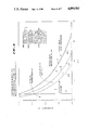
- FIG. 4 is a graph depicting the gain in electrical field strength for various lengths of metal foil and at various distances from the metal foil.
- FIG. 5 is a graph illustrating field strength for a cylindrical shield as a function of the geometry of the shield.
- FIG. 6 is a graph depicting the heating effects of microwave radiation upon wet paper as compared with water.
- FIG. 7 is a graph depicting contour plots showing voltage gain as a function of thickness and dielectric properties.
- FIG. 8 is a graph depicting contour plots showing temperature gains as a function of thickness and dielectric properties.
- FIG. 9 is a graph depicting performance of an idealized food and package combination.
- FIG. 10 is a side view of a probe used to measure electrical field strength.
- FIG. 11 is a graph depicting a calibration curve for the probe of FIG. 10.
- FIG. 1 shows a cut-away view of a microwave food package 1 employing a metal shield 2 wrapped around a dielectric support, member or container 3.
- the package 1 includes a removable top 4 that is also covered by a metal shield 2'.
- FIG. 2 is a perspective view of the container 3 with the shield 2 wrapped around it in the form of a foil label 2.
- the food substances include an ice cream layer 5, a sauce layer 6, and a baked good layer 7.
- the baked good layer 7 may be a brownie layer 7.
- the metal shielding 2 and 2' forms a shielded zone in the container 3 which keeps the ice cream 5 freon while the baked good 7 is heated by microwave radiation.
- metal shielding 2 or a conductive sheet 2 around the container 3 has resulted in unexpected problems during microwave heating. It has been discovered that the metal foil 2 creates regenerated electrical fields, particularly concentrated around the edge 8 of the metal foil 2, that intensify the electrical field strength during microwave heating. This intensification can be as great as 50 times the average field strength where metal shielding is not used. In the intense fields which may occur when metal shielding 2 is employed around a food container 3 during microwave heating, some packaging materials used for the container 3 which normally have insignificant microwave absorption have been observed to melt or decompose in a matter of seconds.
- FIG. 3 illustrates a computer generated graph of electrical field lines which may result during microwave heating. As shown in FIG. 3, the maximum electrical field strength tends to occur near the edge 8 of the shield 2.
- FIG. 4 represents the results of an experiment where strips of aluminum foil taped to paper were exposed to microwave energy.
- the heating rate of the paper was measured at the foil edge (i.e., 0.05 inch), 0.1 inch from the foil, and 0.5 inch from the foil. This was then compared to the heating rate of paper without any foil. Temperatures were measured with a Luxtron probe taped to the paper. The ratio of temperature with the metal strip versus temperature without the metal strip is expressed as "gain" in FIG. 4.
- the amount of gain is virtually negligible at distances greater than 1/2 inch from the edge of the metal foil 2.
- the gain in electrical field strength can be quite high, especially where the length of the metal shield 2 approaches resonance.
- curve 9 represents the gain as a function of the length of a metal strip of foil at a distance of 0.5 inch from the edge of the foil.
- Curve 10 represents the gain at a distance of 0.1 inch from the edge of the metal foil strip. At this distance, the effect of gain upon a dielectric packaging material becomes appreciable, and the present invention is particularly applicable.
- Curve 11 represents the gain at a distance of 0.05 inch from the edge of the metal foil strip.
- the metal shields 2 and 2' have a greater effect upon the dielectric material of the support 3 and top 4 when the metal shields 2 and 2', respectively, have a resonant length. At resonance, the strength of the electric field around the edges 8 of the metal shield 2 increases dramatically.
- FIG. 5 is a graph illustrating the results of experiments upon a variety of cylindrically shaped paper containers 3 having shields 2 wrapped around the containers 3.
- the cylinders 3 were tested for hot spots by coating the package with cellulose acetate.
- the particular cellulose acetate compound employed turned dark at 290° F.
- the graph of FIG. 5 illustrates the amount of blackening that occurred over the aluminum foil shielded cylinder 3, as observed by the reaction of the acetate material to the heating of the paper.
- This experiment provides further information showing the effects of resonance and gain in electrical fields which may occur when metal shielding 2 is used in a package 1.
- the intense electrical field at the base 8 of the metal foil label 2 caused paper to brown and char.
- the intense electrical field also caused crystallized polyester terephthalate ("CPET"), which is normally considered to be a high heat stability plastic, to melt.
- CPET crystallized polyester terephthalate
- Phenolic a material that normally remains intact to 1000° F., decomposed in the presence of the metal foil 2 during microwave heating.
- the effect of electrical field strength in a microwave oven that is "loaded” with a food to be heated can be calculated from the rate of temperature rise of the food.
- the relevant relationship may be expressed as: ##EQU1## where ⁇ is the angular frequency in radians per second, Eo is the dielectric constant of free space, E" is the dielectric loss factor of the material that is being heated, Erms is the root mean square electrical field strength of the microwave energy heating the material, C p is the heat capacity of the material, and ⁇ is the density of the material.
- dT represents the change in temperature
- dt represents the microwave heating time.
- the ratio of dT/dt is the rate of heating.
- the term "dielectric loss factor", represented by the symbol E" will be understood by those skilled in the art to be expressed relative to the dielectric of free space.
- Table I lists relevant properties of six materials which were evaluated for possible use as material for the container 3.
- E' represents the dielectric constant of the material.
- E" represents the dielectric loss factor of the material. Of course, E" should always be measured at the frequency of interest, i.e., the frequency of the microwave oven.
- C p is the heat capacity of the material, and ⁇ is the density of the material.
- the melting temperature, or decomposition temperature, is also listed where applicable. The information for Table I was taken, in part, from Plastics Materials & Processes, by Seymour S. Schwartz and Sidney H. Goodman (1982), published by Van Nostrand Reinhold Co.
- the melting temperature for CPET is relatively high, and the decomposition temperature for paper and phenolic resin are relatively high, it has surprisingly been found that polypropylene and high density polyethylene are especially preferred materials for the composition of the container 3, particularly in the area near the edge 8 of the shield 2, while phenolic resin, paper and CPET are unsuitable.
- Equation 1 was used to calculate the theoretical temperature rise for the packaging materials listed in Table I.
- failing temperature or “failure temperature” are used herein to refer to the melting temperature, if the material 3 is a material that melts, or the decomposition temperature, if the material 3 is a material that decomposes. "Failure temperature” also includes the temperature at which any undesirable change occurs in the package material 3, such as deformation, discoloration, charring, detrimental outgassing, or detrimental softening.
- the actual temperature rise may depend upon changes in dielectric loss which may occur during heating, and changes in Erms which may occur.
- FIG. 6 is a graph illustrating the heating rate of wet paper as compared with the heating rate of water. Although wet paper initially heats very rapidly, in the experiment represented in FIG. 6, the heating rate of the wet paper rapidly leveled off at about 60° C. This is shown by curve 12 in FIG. 6. Curve 13 represents the heating rate of water.
- Polystyrene also lasted longer than six minutes. Polystyrene, however, has a tendency to fail if an arc occurs. In one experiment, the occurrence of an arc resulted in a fire. In some applications, polystyrene may be an undesirable microwave packaging material for use in connection with a metal shield 2, because arcing can sometimes occur when a metal shield 2 is employed. Formulations for polystyrene may be developed which overcome such problems.
- the time to failure of the packaging materials listed in Table V generally follows the calculated results based upon experimental measurements. The actual time to failure was also believed to be a function of heat transfer rate. To some extent, the dielectric constant and/or dielectric loss factor of the material was believed to change with temperature in some cases.
- high density polyethylene and polypropylene are especially preferred materials for a microwave shielded container 3.
- Other preferred materials include copolymers of polypropylene and polyethylene.
- Copolymers of polypropylene and polyethylene are either a blend or copolymerization of polypropylene, polyethylene and EPR (an ethylene/propylene rubber formed during copolymerization).
- the final product used in packaging is generally 12-14% EPR, about 2% polyethylene and the balance polypropylene.
- the percentage of polyethylene may be varied. As more polyethylene is added to the blended composition, impact strength increases and temperature resistance decreases. Thus, the amount of polyethylene added to the composition involves a tradeoff between impact strength and temperature resistance. For example, about 20% polyethylene is used in copolymers from which automobile parts are fashioned where impact strength is an important consideration. EPR levels of up to 21% have been used in some applications, but such large percentages of EPR are not typically utilized in food applications.
- a suitable copolymer that has given good results in practice is made by Himont U.S.A., Inc., under the trademark PROFAX 7531, intermediate impact propylene copolymer for food packaging.
- copolymers of polypropylene and polyethylene oftentimes perform with equivalent results as polypropylene alone, with the exception of melting temperature.
- the essential characteristics of specific gravity, heat capacity and dielectric loss factor are not significantly affected in most copolymer compositions.
- High density polyethylene having a specific gravity of about 0.95 or greater and a melting temperature of about 115° C. or higher is believed to give satisfactory results.
- a high density polyethylene having a crystallinity of about 90% or greater may give good results.
- a high density polyethylene having a softening temperature of about 266° F. and a density of about 0.952 to about 0.958 g/cc has been used in practice with good results.
- the dielectric support 3 should be preferably composed of a material having a heat capacity of about 0.5 calories per gram degrees centigrade, or greater. A dielectric support 3 having a density of about 0.89 grams per cubic centimeter, or greater, is preferred.
- the metal shields or conductive sheets 2 and 2' preferably are composed of aluminum.
- the metal shields 2 and 2' could generally be any type of conductive sheets. Any metal may be used for the shields 2 and 2' if it is a good conductor. Suitable metals include gold, silver, steel, copper and tin.
- the conductive sheets 2 and 2' preferably are in contact with the support 3.
- contact includes examples or embodiments where the conductive sheets 2 and 2' are adhesively bonded to the container 3, even though a thin layer of adhesive may actually be interposed between the conductive sheet 2 or 2' and the container 3.
- the illustrated conductive sheets 2 and 2' are uncoated.
- metal foil used in a microwave oven has been coated with insulating plastics in an effort to control arcing. Such coatings tend to reduce the electrical field strength Erms which impinges upon the packaging material. Such coating techniques are relatively expensive, and are unnecessary using the present invention.
- polyethylene is considered to be a suitable packaging material for many applications. Table VI below lists the properties for polyethylene in terms of density, melting temperature, and percent crystallinity:
- packaging materials normally have an insignificant rate of heating in a microwave oven as compared to the heating rate of food.
- metal foil shielding 2 to intensify the electrical field at the edges 8 of the foil shield 2 by as much as 50 times the average field strength.
- selecting a packaging material for heat stability is an insufficient basis for making a selection.
- a low microwave loss factor has been discovered to be a necessary requirement when a dielectric container 3 includes metal shielding 2.
- the time to failure of packaging materials may be expressed as: ##EQU2## where t f is the time to failure for the packaging material, measured in seconds. T f is the failure temperature in degrees centigrade for the packaging material. For most materials, this is the melting temperature. For some materials, it is the decomposition temperature. T i is the initial package temperature, expressed in degrees centigrade. ⁇ is the density of the packaging material, expressed in kilograms per cubic meter. C p is the heat capacity of the packaging material, expressed in joules per kilogram degree centigrade. Eo is the dielectric constant of free space, which is equal to about 8.8 ⁇ 10 -12 farads per meter.
- ⁇ is the angular frequency of electromagnetic radiation, which in the case of a typical microwave oven is 2 ⁇ 2.45 ⁇ 10 9 per second.
- E is the dielectric loss factor of the packaging material.
- Erms is the root means square electric field strength, expressed in volts per meter, which is applied to the packaging material. Erms is the local field intensity measured at, or as near as possible to the edge 8 of the shield 2. Erms can be measured using a probe, such as shown in FIG. 10 and described below.
- packaging materials may be evaluated to determine whether they will be suitable when subjected to the high Erms electric fields which may result when metal shielding is used in a microwave oven.
- the packaging material is selected so that the heating of the dielectric packaging material is such that the period of time necessary to properly heat the food substance which is to be heated is less than the time to failure.
- a suitable packaging material is selected which has a combination of density, heat capacity, and dielectric loss factor so that the time to failure will not be less than the necessary heating time for the food which is to be heated in a microwave oven.
- the microwave heating time before failure of the container 3 can be calculated.
- High density polyethylene and polypropylene have been discovered to be good materials for the dielectric container 3. These materials have both a high heat stability and a low dielectric loss factor.
- CPET which has a higher heat stability, will actually reach its melting point faster because it has a higher dielectric loss factor.
- paper has a very high decomposition temperature, paper will brown or even char at the edges 8 of the foil shield 2 because its loss factor is orders of magnitude higher than most other packaging materials.
- a good packaging material is determined by a combination of material characteristics. One factor may be varied, and a second factor may also be simultaneously varied, so that the two factors equally offset each other. The net result would be two different packaging materials which were equivalent for purposes of this invention.
- a good packaging material depends on a combination of density, heat capacity, and dielectric loss factor. The density could be reduced, and the loss factor could be simultaneously reduced by an equal factor or a proportionate amount, to result in an equivalent packaging material. Similarly, the heat capacity could be reduced, and the density could be increased by an amount so that the product of the two was the same, to yield equivalent results. What is important is the ratio of the dielectric loss factor divided by the product of the heat capacity times the density. Any combination of these three factors which yields an identical answer should produce equivalent results.
- the dielectric loss factor is the most important factor.
- the dielectric loss factors of the various materials may vary by orders of magnitude, whereas typical densities and heat capacities may not vary as widely.
- FIG. 7 is a graph which shows a contour plot for voltage gain as a function of thickness and dielectric properties of the packaging material. These contour plots illustrate the effect of dielectric loss and material thickness on voltage gain. FIG. 7 shows that gain generally increases as dielectric loss factor decreases.
- FIG. 8 is a graph showing contour plots for temperature gain as a function of thickness and dielectric properties of the packaging material. The information graphed in FIG. 8 was measured with an infrared camera.
- FIG. 8 it may be seen that, at higher dielectric loss factors, thickness of the packaging material 3 makes more of a difference. At the lowest dielectric loss factor shown in FIG. 8, thickness makes less of a difference.
- the graph of FIG. 8 also shows that, at high loss factors, the rate of temperature rise is limited by the fact that the high dielectric loss tends to reduce the electrical field strength. In other words, the loading tends to "damp" the system. This may be better understood by considering FIG. 7 in conjunction with FIG. 8. At low values for the dielectric loss factor, the heating effects of the electrical field are not as significant because of the lower dielectric loss. In an intermediate range of dielectric loss factors, generally shown in FIG.
- the rate of temperature rise may be expressed as follows: ##EQU3##
- a procedure or method has been developed for measuring a value for Erms to be used in the above calculations.
- the preferred procedure uses a Luxtron fluoroptic thermometry system. This system is preferred because it is a non-field-perturbing method of measurement in a microwave electrical field.
- Two probes are set up as shown in FIG. 10 to form a probe assembly 21.
- an active Luxtron temperature probe 14 is constructed having a square piece of susceptor material 15 attached to the end thereof.
- the susceptor 15 is preferably made from a 1.5 mm ⁇ 1.5 mm square of susceptor material having a resistivity of about 1200 ohms per square.
- the susceptor 15 preferably comprises a sheet of metallized polyester.
- a thin film of stainless steel was sputtered on a sheet of 92 gauge polyester material. It is preferred that the sheet of metallized polyester not be bonded to a sheet of paper or other material, in order to minimize the effect upon thermal mass which such a sheet of paper or other material would have.
- the susceptor 15 is preferably attached to the probe 14 with vacuum grease, or other suitable adhesive.
- a second ambient Luxtron temperature probe 16 is attached to the active Luxtron probe 14, or may be disposed in close proximity thereto.
- the second ambient probe 16 measures ambient air temperature near the active probe 14.
- the ambient Luxtron probe is spaced 3 millimeters from the end of the active Luxtron probe having the susceptor 15 attached thereto.
- the illustrated Luxtron probes 14 and 16 have a diameter of 1.3 millimeters.
- the calibration procedure preferably uses an adjustable microwave power source having a known or measurable power output. This may be used in conjunction with a wave guide having known characteristics.
- a Gerling Moore high power microwave source sold under the trademark of "Genisys" is used in conjunction with a rectangular WR-284 wave guide.
- a known power input is placed into the wave guide.
- the electric field strength Erms can be calculated based upon the following formula: ##EQU4## where P is the known power transmitted into the wave guide, expressed in watts; a is the width of the wave guide, in this example 0.0721 meters; b is the height of the wave guide, in this example 0.034 meters; ⁇ 0 is the wavelength of the microwaves, in this example 0.124 meters; k is equal to 2 ⁇ divided by ⁇ 0 ; ⁇ 0 is the impedance of free space, in this example 376.7 ohms; Erms is the electrical field strength expressed in volts per meter; k' is the wave number of the wave guide, in this example it is equal to: ##EQU5##
- the Luxtron probe assembly 21 illustrated in FIG. 10 is placed in the wave guide described above for calibration. A known microwave power level is then transmitted into the wave guide. The active Luxtron probe 14 is allowed to reach a steady state temperature. This usually occurs within seconds. Thus, a steady state temperature differential may be measured between the active Luxtron probe 14 and the ambient Luxtron probe 16. This temperature differential may be measured for several power settings. The temperature differential, expressed as ⁇ T, may be plotted versus Erms on a graph. Such a calibration plot of ⁇ T versus electric field strength Erms is shown in FIG. 11.
- the probe assembly 21 may be inserted into a microwave oven to measure the actual electrical field strength in the oven.
- the calibration curve shown in FIG. 11 is used to determine the electrical field strength Erms at the measured point.
- the composite Luxtron probe assembly 21 may be advantageously used to measure electrical field strength Erms adjacent a metal shield 2 on a microwave container 3.
- the active Luxtron probe 14 shown in FIG. 10 is sensitive to electric fields in the plane of the susceptor 15. This particular probe has a minimal response to electric fields which are perpendicular to the plane of the susceptor 15. Thus, measurements may be affected by the orientation of the susceptor 15. Multiple measurements using different probe orientations may be taken to determine an average electrical field strength. In some cases, for example where a shield 2 is responsive to microwave energy having a particular polarization, the probe 14 may offer the advantage of measuring only the electrical field strength of interest.
- Luxtron model MIC-02-10093 probes 14 and 16 were used.
- the probes 14 and 16 are connected to a Luxtron fluoroptic thermometry system, Model No. 750.
- the angular frequency w was equal to 2 ⁇ 2.45 ⁇ 10 9 cycles per second.
- the dielectric of free space Eo was equal to 8.8 ⁇ 10 -12 farads per meter.
- a packaging material will fail if the time to failure t f is less than the product preparation time required in order to properly heat or cook the particular food product in a microwave oven.
- a more preferred criteria for selecting a suitable package material is that the dielectric container 3 should not heat more than the food substance 5, 6 or 7 within the container 3.
- the temperature rise in the packaging material 3 may be measured using a Luxtron temperature probe.
- the temperature rise in the package material 3 may be calculated as follows: ##EQU8## where ⁇ T p is the temperature rise in the package material or container 3; ⁇ t is the heating time for the food product in seconds; Erms is the maximum local electrical field strength, typically at the edge 8 of the shield 2; ⁇ p is the density of the package material 3; (C p ) p is the heat capacity of the package material 3; and, E p " is the dielectric loss factor for the package material 3.
- the temperature rise in each food substance 5, 6 or 7 may be measured using a Luxtron temperature probe.
- the temperature rise in each food substance 5, 6 or 7 may also be separately calculated.
- the temperature rise in each food substance may be calculated using techniques disclosed in application Ser. No. 922,573, filed Oct. 23, 1986, by John R. Weimer, entitled “Food Product and Method of Manufacture", which is incorporated herein by reference.
- a simplified approach may be effectively utilized.
- the food substance which heats the most is of primary interest, and may be used for purposes of this criteria in selecting a suitable package material.
- only the temperature rise in the food substance 7 which is heated the most need be considered for purposes of this criteria. In many applications, only one food substance 7 will be desired to be heated.
- the temperature rise of the food substance 7 may be calculated from the following equation: ##EQU9## where ⁇ T F is the temperature rise of the food substance 7; ⁇ t is the heating time for the food, expressed in seconds; E F " is the dielectric loss factor for the food substance 7; ⁇ F is the density of the food substance 7; (C p ) F is the heat capacity for the food substance 7; Erms' is the local electrical field strength within the food substance 7. The average electrical field strength is utilized in this calculation.
- the temperature rise in both the package 3 material and the food substance 7 may be calculated.
- the temperature rise in the package ⁇ T p should not be greater than the temperature rise ⁇ T F in the food substance 7.
- An additional criteria for selecting an even more preferred packaging material may be based upon selecting a package material 3 which does not exceed a maximum temperature of 60° C. during the heating time ⁇ t utilized to heat the food substance 7.
- ⁇ F 400 kilograms per cubic meter
- C p 1256 J/kg°C.
- E" F 0.5.
- an electrical field strength Erms of 3000 volts per meter is present.
- a temperature rise of about 72.7° C. results.
- the brownie food substance 7 reaches a maximum temperature of about 93.7° C. during this one minute heating time.
- a preferable container material 3 should be selected so that the package 3 does not have a temperature rise greater than the temperature rise of the food substance 7.
- the package material should not rise more than 72.7° C. for a one minute heating time. (Of course, it is also necessary that the packaging material 3 not exceed its failure temperature during this time.)
- the above-described principles may also be used, in connection with the relationships described below, to determine the maximum gain of the shield 2 which is permissible based upon the criteria used for selecting a suitable packaging material 3. That is, the maximum gain may be determined to avoid failure of the packaging material 3, or alternatively, the maximum gain may be determined for a preferred packaging material 3 which does not heat faster than the food product.
- the equation below may be used to calculate Erms for a package using CPET to determine maximum allowable gain which would comply with each of the three criteria discussed above: ##EQU10##
- the maximum field strength in order to satisfy the above three criteria may be calculated.
- the maximum field strength which may be reached to prevent failure of the packaging material 3 may be calculated.
- the maximum field strength to ensure that the package material 3 remains cooler than the food substance 7 may be determined for a preferred packaging material.
- the maximum electrical field strength for an even more preferred packaging material 3 which does not exceed 60° C. may also be calculated.
- the electrical field strength Erms may be measured for an identical package 1 which does not have a shield 2. If the measured Erms is 3000 volts per meter, then the gain may be calculated as follows:
- the gain in electrical field strength at the edge 8 of the shield 2 cannot exceed 11.8 if the package material 3 is not to reach a temperature hotter than the brownie 7.
- a less preferred condition, but a necessary condition, is that the package material 3 be selected so that the package material 3 does not reach a temperature sufficient to melt the package material 3.
- the melting point or failure temperature T f equals 235° C.
- the temperature rise for the package material 3 may be calculated as follows, assuming an initial temperature T i of 21° C.:
- the value of the electrical field Erms may be calculated.
- the Erms value which will cause melting of the CPET is 60,627 volts per meter.
- a container 3 composed of CPET will fail in this example if the gain is greater than 20.2.
- the package 3 should not exceed a temperature of 60° C. during the heating time ⁇ t.
- the maximum electrical field strength Erms may be calculated. In this case, Erms equals 25,880 volts per meter.
- the gain in the electrical field strength due to the presence of the shield 2 may not be greater than 8.6 for this more preferred region of operation.
- the gain required to make polyethylene fail Using the above analysis, one can also determine the gain required to make polyethylene fail. Using a melting or failure temperature of 115° C., the gain must equal 43.6 in order for polyethylene to fail. One can also calculate the maximum gain for a preferred package which does not become hotter than the food product. The maximum permissible gain for polyethylene to still attain this preferred condition is 38.4.
- the gain in this example would equal 9.
- FIG. 9 is a graph depicting gain versus the dielectric loss factor for an example of a food and package combination.
- FIG. 9 used an example which employed typical ranges for heat capacity, specific gravity, and microwave heating time.
- the vertical axis shows log 10 (E").
- FIG. 9 illustrates the general relationship between dielectric loss factor E" and gain.
- the actual oven, food and package characteristics may be used to produce a graph which accurately reflects the characteristics for that particular example.
- a graph similar to that shown in FIG. 9 may be plotted to determine the acceptable gain for the three given criteria for selecting a packaging material for the container 3.
- a graph such as shown in FIG. 9 may be plotted where curve 17 represents the maximum gain for any given dielectric loss factor which would result in failure of the container 3.
- Curve 18 represents the maximum gain permissible, as a function of dielectric loss factor, to maintain the container 3 at a temperature less than the food 7.
- Curve 19 represents the maximum gain, as a function of dielectric loss factor E", necessary to maintain the temperature of the container 3 less than 60° C.
- Curve 20 represents a region of operation where package failure is unlikely to occur regardless of the material selected for the container 3, due to the low gain. It has been discovered that the benefits of the present invention are not as significant in the region where the gain is less than about 3.
- the present invention involves nonarcing packages or containers 3, 4 for heating food in a microwave oven.
- intrinsically nonarcing it is meant that the package does not itself arc, e.g., result in arc discharges from one package component to another, or to the food, or to the floor of the oven.
- An "intrinsically nonarcing" package can sometimes be made to arc if placed too closely to adjacent food packages or metallic oven components other than the floor of the oven. Arcs which result in that manner are not considered for purposes of defining an "intrinsically nonarcing" package.
- an "intrinsically nonarcing" package can be made to arc if it is brought too closely to metallic oven components or to another package.
- the present invention arose as a result of the successful development of intrinsically nonarcing packages. It was only after such nonarcing packages had been developed that the problems solved by the present invention were recognized.
- the gain resulting from metal components may be adjusted, for example, by changing the dimensions of the metal sheet 2. In some instances, the geometry of the metal components may be changed, such as by providing overlapping edges. Other techniques for adjusting the gain of the package are disclosed in application Ser. No. 922,287, filed Oct. 23, 1986.
- the tolerance and reproducibility of the heating effects upon the food are an important consideration. Tolerance and reproducibility of results depends significantly upon the dimensional stability of the container 3 and shield configuration. This may be broken down into two considerations: first the shield 2 must remain dimensionally stable during microwave heating in order to maintain a consistent modification of electric field, or else reproducibility of microwave heating effects on the food will be difficult; and, second the food containing cavity defined by the container 3, 4 must be dimensionally stable and essentially rigid. A variation in the configuration of the food containing cavity may affect the reproducibility and consistency of the heating effects upon the food from one package to another.
- a rigid, dimensionally stable dielectric container 3 is preferred.
- the container 3 supports the conductive sheet 2, which is wrapped around the container 3.
- the dimensional stability of the conductive sheet 2 is also maintained by the rigidity of the container 3.
- the present invention is particularly concerned with package materials 3 which are formed from organic compounds, i.e., compounds containing carbon atoms.
- Organic compounds are more likely to be affected adversely by undue levels of microwave heating when exposed to relatively high electric field strengths resulting from gain due to conductive elements in the microwave package 1.
- the present invention is also particularly concerned with microwave environments of the type encountered in microwave ovens.
- the selection of suitable dielectric materials 3 for packages 1 which may only be exposed to extremely low field strength levels is not critical.
- the present invention is particularly applicable in microwave environments where the average electric field strength Erms is greater than 1 v/cm.
- the package 1 is designed to survive microwave radiation in the enclosed cavity of a microwave oven having a power input of at least 10 watts, more typically in excess of 400 watts.
- the present invention is concerned with microwave packaging systems where the food material involved presents a low load to the microwave oven.
- the average electric field strength Erms will depend upon the particular load which is placed in the microwave oven. In a heavily loaded oven, the electric field strength will be lower. In a food package using a heavy load such as a meat roast, the oven will be so heavily loaded that the electric field strength Erms will be so low as to virtually eliminate the possibility of causing the packaging material to exceed its failure temperature.
- the present invention is applicable for food materials which present a low load to the microwave oven, because in such instances, the electric field strength Erms can reach sufficiently high levels to cause the packaging material to fail if it is not properly selected in accordance with the present invention.
- the term "low load” means that the average electric field strength in the immediate vicinity of the package or food can reach 10 volts per centimeter or greater. This condition may be shown to be satisfied by using two measurement techniques.
- a Luxtron probe assembly 21 as illustrated in FIG. 10 may be used to measure the electric field strength in the immediate vicinity of the package 1. In making such a measurement, it is important to measure the average electric field strength around the package by taking measurements at several locations spaced approximately 1/2 inch to 1 inch from the surface of the package 1. In some instances, reflections from metal components 2 in the package 1 may produce spurious readings.
- the temperature rise ⁇ T in the food may be measured using a Luxtron temperature probe.
- the density ⁇ , heat capacity C p and dielectric loss factor E" for the food may also be measured.
- the microwave heating time ⁇ t is also known, as well as the angular frequency ⁇ of the microwave radiation and the dielectric constant of free space Eo. These values may be substituted into the equation for calculating Erms as follows: ##EQU13##
- a low load food product may result from two different factors.
- the food may be a low loss food, i.e., the dielectric loss factor E" for the food may be a relatively low value.
- the dielectric loss factor E for the food may be a relatively low value.
- relatively glossy foods may constitute a low load where only small amounts of the food are present in the microwave oven. For example, quantities of food less than 200 grams may present a low load in a microwave oven even if the food has a relatively high dielectric loss factor E".
- the temperature of the food will typically be elevated to 100° C. or greater. In applications where the food is reheated, the temperature of the food will typically be elevated to 60° C. or greater.
- Other applications may include thawing frozen food. Although some thawing applications may not involve a significant elevation of the food temperature, the package 1 is exposed to a significant level of microwave radiation for purposes of thawing the food, which does involve an appreciable amount of energy transfer as latent heat in order to change the state of water molecules in the food. Other applications may involve warming frozen food to room temperature, which typically involves a change of food temperature from about 0° C. or less to about 21° C.
- conductive members 2 in a package 1 result in a gain.
- susceptor material is not considered to be "conductive.” It is believed that gain within the meaning of the present invention does not result for susceptor members or sheets having a resistivity greater than 10 ohms per square.
- a conductive sheet member or element 2 means a conductive material which has a resistivity of less than 1 ohm per square, more preferably less than 0.1 ohm per square.
- a conductive material is a material in which a relatively large current flows when a potential is applied between two points on or in a body constructed from the material.
- Metal foil is considered to be conductive material for purposes of this invention. Typical metal foil thicknesses range between 0.000275 inch and 0.006 inch.
Abstract
Description
                                  TABLE I
__________________________________________________________________________
MATERIAL TESTED
          E'
            E"  C.sub.p cal/g °C.
                       ρ g/cc
                           Melting °C.
                                 Decomposition
__________________________________________________________________________
H.D. Polyethylene
          2.2
            0.0013
                0.5    0.92
                           115
Polypropylene
          2.2
            0.0011
                0.5    0.9 176
CPET      3.0
            0.015
                0.5    1.0 235
Polystyrene
          2.5
            0.00083
                0.32   1.07
                           100
Phenolic Resin
          3.5
            0.148
                0.4    1.1       540° C.
Paper     2.7
            0.15
                0.5    0.3       200-250° C.
__________________________________________________________________________
              TABLE II
______________________________________
PREDICTED TEMPERATURE RISE
                  Temperature Rise
                  °C./sec
______________________________________
Water               0.559
H.D. Polyethylene   0.00013
Polypropylene       0.00020
CPET                0.00139
Polystyrene         0.00013
Phenolics           0.0156
Paper               0.0467
______________________________________
              TABLE III
______________________________________
OBSERVED HEATING RATES
            Temperature Rise
            °C./sec
                         Erms V/M
______________________________________
Water         0.572          1,200
H.D. Polyethylene
              0.0878         30,992
Polypropylene 0.078          23,410
CPET          0.1245         11,327
Phenolics     0.38           5,909
Paper         1.069          5,748
Wet Paper     2.612          3,957
______________________________________
              TABLE IV
______________________________________
EFFECT OF RESONANCE IN FOIL
         °C./sec RATEHEATING
                 KV/mErms
                         ##STR1##
______________________________________
H.D.      0.695     87.2    7.91
Polyethylene
Polypropylene
          1.355     97.6    17.37
CPET      1.611     40.7    12.94
Phenolics 1.574     12.0    4.14
Paper     7.11      14.8    6.65
Wet Paper 38.3      15.1    14.66
______________________________________
              TABLE V
______________________________________
PACKAGING MATERIALS TIME TO FAILURE
                   PREDICTED  OBSERVED
           FAILURE FAILURE    FAILURE
           TEMP °C.
                   TIME       TIME
______________________________________
H.D. Polyethylene
             115       551 sec.   >6 min.
Polypropylene
             176       390 sec.   >6 min.
CPET         235       146 sec.   27 sec.
Phenolic     540       20.5 sec.  27 sec.
Paper        500       1.1 sec    18 sec.
Polystyrene  100       --         >6 min.
______________________________________
              TABLE VI
______________________________________
                              %
              ρ g/cc
                     T.sub.m °C.
                              Crystallinity
______________________________________
Polypropylene   .89-.92  149-180  50-70%
Linear low density
                .91-.93  120-130  35-45%
polyethylene
Low density polyethylene
                 .91-.927
                         105-115  40-65%
Medium density polyethylene
                .928-.94 115-127  55-75%
High density polyethylene
                .94-.97  127-138  65-90%
______________________________________
Gain=35,336÷3,000=11.8
ΔT.sub.p =T.sub.f -T.sub.i
ΔT.sub.p =235° C.-21° C.
ΔT.sub.p =214° C.
Claims (39)
Priority Applications (1)
| Application Number | Priority Date | Filing Date | Title |
|---|---|---|---|
| US07/113,171 US4894503A (en) | 1987-10-23 | 1987-10-23 | Packages materials for shielded food containers used in microwave ovens |
Applications Claiming Priority (1)
| Application Number | Priority Date | Filing Date | Title |
|---|---|---|---|
| US07/113,171 US4894503A (en) | 1987-10-23 | 1987-10-23 | Packages materials for shielded food containers used in microwave ovens |
Publications (1)
| Publication Number | Publication Date |
|---|---|
| US4894503A true US4894503A (en) | 1990-01-16 |
Family
ID=22347954
Family Applications (1)
| Application Number | Title | Priority Date | Filing Date |
|---|---|---|---|
| US07/113,171 Expired - Lifetime US4894503A (en) | 1987-10-23 | 1987-10-23 | Packages materials for shielded food containers used in microwave ovens |
Country Status (1)
| Country | Link |
|---|---|
| US (1) | US4894503A (en) |
Cited By (33)
| Publication number | Priority date | Publication date | Assignee | Title |
|---|---|---|---|---|
| US5256846A (en) * | 1991-09-05 | 1993-10-26 | Advanced Dielectric Technologies, Inc. | Microwaveable barrier films |
| US5300747A (en) * | 1989-07-17 | 1994-04-05 | Campbell Soup Company | Composite material for a microwave heating container and container formed therefrom |
| US5317119A (en) * | 1988-10-17 | 1994-05-31 | Nu-Tech & Engineering, Inc. | Oven safe disposable food container |
| US5387404A (en) * | 1988-04-21 | 1995-02-07 | Flexiclave, Inc. | Process and apparatus for heat disinfecting soft contact lenses |
| US5416304A (en) * | 1990-11-13 | 1995-05-16 | Kraft General Foods, Inc. | Microwave-reflective device and method of use |
| US5593610A (en) * | 1995-08-04 | 1997-01-14 | Hormel Foods Corporation | Container for active microwave heating |
| US5718370A (en) * | 1996-05-23 | 1998-02-17 | Fort James Corporation | Partially shielded microwave heating container |
| US6222168B1 (en) | 1995-10-27 | 2001-04-24 | Medical Indicators, Inc. | Shielding method for microwave heating of infant formulate to a safe and uniform temperature |
| US20040108313A1 (en) * | 2002-12-10 | 2004-06-10 | Mars Incorporated | Differential temperature microwavable container |
| US6781101B1 (en) | 2003-02-05 | 2004-08-24 | General Mills, Inc. | Reconfigurable microwave package for cooking and crisping food products |
| US20050136167A1 (en) * | 2002-04-29 | 2005-06-23 | Kraklow Harry K. | Frozen microwaveable bakery products |
| US20060096978A1 (en) * | 2004-11-10 | 2006-05-11 | Graphic Packaging International, Inc | Insulated packages for microwaveable foods |
| US20070228036A1 (en) * | 2006-03-31 | 2007-10-04 | Marie-Line Noyelle | Microwavable construct for heating, browning, and crisping rounded food items |
| WO2007113545A1 (en) | 2006-04-03 | 2007-10-11 | H J Heinz Company Limited | Microwavable packaging for food products |
| US20080023469A1 (en) * | 2006-07-27 | 2008-01-31 | Fitzwater Kelly R | Microwave heating construct |
| EP1965607A1 (en) | 2007-02-27 | 2008-09-03 | BARILLA G. E R. FRATELLI S.p.A. | Microwave oven and apparatus for preparing ready-to-eat meals including said microwave oven |
| US20080248168A1 (en) * | 2006-04-20 | 2008-10-09 | John Mark Black | Frozen microwaveable dough products |
| US20080260926A1 (en) * | 2003-04-29 | 2008-10-23 | First Products, Inc. | Frozen Microwavable Bakery Products |
| US20090039076A1 (en) * | 2007-08-09 | 2009-02-12 | Albert Vincent Maslowski | Multi-Compartment Microwaveable Food Container |
| US7514659B2 (en) | 2005-01-14 | 2009-04-07 | Graphic Packaging International, Inc. | Package for browning and crisping dough-based foods in a microwave oven |
| US20100038359A1 (en) * | 2008-08-14 | 2010-02-18 | Vicki Laubhan | Microwave Heating construct with elevatable bottom |
| US20100213191A1 (en) * | 2009-02-23 | 2010-08-26 | Middleton Scott W | Low Crystallinity Susceptor Films |
| US20100230403A1 (en) * | 2009-03-11 | 2010-09-16 | Jay Daniel Hodson | Microwave cooking containers with shielding |
| US20110011854A1 (en) * | 2009-02-23 | 2011-01-20 | Middleton Scott W | Low crystallinity susceptor films |
| EP2459624A2 (en) * | 2009-07-30 | 2012-06-06 | Graphic Packaging International, Inc. | Low crystallinity susceptor films |
| US20130087556A1 (en) * | 2011-10-05 | 2013-04-11 | Kathyrn Marie Birchmeier | Method for Preparing a Multi-Texture Food Product Using Microwave Interactive Packaging |
| US8445043B2 (en) | 2009-12-30 | 2013-05-21 | H.J. Heinz Company | Multi-temperature and multi-texture frozen food microwave heating tray |
| WO2013136102A1 (en) * | 2012-03-12 | 2013-09-19 | Coneinn Marketing, B.V. | Packaging having field modifiers for improved microwave heating of cone-shaped products |
| US20140014316A1 (en) * | 2012-07-13 | 2014-01-16 | Harris Corporation | Apparatus for transporting and upgrading a hydrocarbon resource through a pipeline and related methods |
| US8853601B2 (en) | 2006-03-31 | 2014-10-07 | Graphic Packaging International, Inc. | Microwavable construct for heating, browning, and crisping rounded food items |
| US20150274400A1 (en) * | 2012-10-12 | 2015-10-01 | General Mills, Inc. | Microwavable food packaging, and related products and methods |
| US9284108B2 (en) | 2009-02-23 | 2016-03-15 | Graphic Packaging International, Inc. | Plasma treated susceptor films |
| EP2974528A4 (en) * | 2013-03-14 | 2016-11-02 | Graphic Packaging Int Inc | Low crystallinity susceptor films |
Citations (30)
| Publication number | Priority date | Publication date | Assignee | Title |
|---|---|---|---|---|
| US3219460A (en) * | 1962-11-20 | 1965-11-23 | Lever Brothers Ltd | Frozen food package and method for producing same |
| US3271552A (en) * | 1963-02-01 | 1966-09-06 | Litton Prec Products Inc | Microwave heating apparatus |
| US3271169A (en) * | 1963-02-01 | 1966-09-06 | Litton Prec Products Inc | Food package for microwave heating |
| US3547661A (en) * | 1968-10-07 | 1970-12-15 | Teckton Inc | Container and food heating method |
| US3615713A (en) * | 1969-09-12 | 1971-10-26 | Teckton Inc | Selective cooking apparatus |
| US3941967A (en) * | 1973-09-28 | 1976-03-02 | Asahi Kasei Kogyo Kabushiki Kaisha | Microwave cooking apparatus |
| US3946188A (en) * | 1975-06-19 | 1976-03-23 | Raytheon Company | Microwave heating apparatus with browning feature |
| US4144438A (en) * | 1977-09-28 | 1979-03-13 | The Procter & Gamble Company | Microwave energy moderating bag |
| US4183435A (en) * | 1978-08-24 | 1980-01-15 | Champion International Corporation | Polymeric multiple-layer sheet material |
| US4190757A (en) * | 1976-10-08 | 1980-02-26 | The Pillsbury Company | Microwave heating package and method |
| US4196331A (en) * | 1978-07-17 | 1980-04-01 | The Procter & Gamble Company | Microwave energy cooking bag |
| US4204105A (en) * | 1978-04-14 | 1980-05-20 | The Procter & Gamble Company | Microwave energy moderating bag |
| US4210674A (en) * | 1978-12-20 | 1980-07-01 | American Can Company | Automatically ventable sealed food package for use in microwave ovens |
| US4228334A (en) * | 1978-11-27 | 1980-10-14 | The Procter & Gamble Company | Dynamic microwave energy moderator |
| US4230924A (en) * | 1978-10-12 | 1980-10-28 | General Mills, Inc. | Method and material for prepackaging food to achieve microwave browning |
| US4233325A (en) * | 1979-09-13 | 1980-11-11 | International Flavors & Fragrances Inc. | Ice cream package including compartment for heating syrup |
| US4268738A (en) * | 1977-09-28 | 1981-05-19 | The Procter & Gamble Company | Microwave energy moderator |
| US4306133A (en) * | 1979-02-14 | 1981-12-15 | Levinson Melvin L | Microwave pie baking |
| US4316070A (en) * | 1979-08-21 | 1982-02-16 | Prosise Robert L | Cookware with liquid microwave energy moderator |
| US4330696A (en) * | 1978-04-17 | 1982-05-18 | Plastics, Inc. | Portable turntable for ovens |
| US4351997A (en) * | 1979-08-27 | 1982-09-28 | Societe d'Assistance Technique pour Porduits Nestle S.A. | Food package |
| US4390554A (en) * | 1975-04-28 | 1983-06-28 | Levinson Melvin L | Microwave heating of certain frozen foods |
| US4398077A (en) * | 1980-10-06 | 1983-08-09 | Raytheon Company | Microwave cooking utensil |
| US4416907A (en) * | 1981-07-13 | 1983-11-22 | Golden Valley Foods Inc. | Process for preparing food packages for microwave heating |
| US4518651A (en) * | 1983-02-16 | 1985-05-21 | E. I. Du Pont De Nemours And Company | Microwave absorber |
| US4626641A (en) * | 1984-12-04 | 1986-12-02 | James River Corporation | Fruit and meat pie microwave container and method |
| US4656325A (en) * | 1984-02-15 | 1987-04-07 | Keefer Richard M | Microwave heating package and method |
| US4661672A (en) * | 1985-01-14 | 1987-04-28 | House Food Industrial Company, Limited | Container for use in heating by microwave oven |
| US4703148A (en) * | 1986-10-17 | 1987-10-27 | General Mills, Inc. | Package for frozen foods for microwave heating |
| US4777053A (en) * | 1986-06-02 | 1988-10-11 | General Mills, Inc. | Microwave heating package |
-
1987
- 1987-10-23 US US07/113,171 patent/US4894503A/en not_active Expired - Lifetime
Patent Citations (30)
| Publication number | Priority date | Publication date | Assignee | Title |
|---|---|---|---|---|
| US3219460A (en) * | 1962-11-20 | 1965-11-23 | Lever Brothers Ltd | Frozen food package and method for producing same |
| US3271552A (en) * | 1963-02-01 | 1966-09-06 | Litton Prec Products Inc | Microwave heating apparatus |
| US3271169A (en) * | 1963-02-01 | 1966-09-06 | Litton Prec Products Inc | Food package for microwave heating |
| US3547661A (en) * | 1968-10-07 | 1970-12-15 | Teckton Inc | Container and food heating method |
| US3615713A (en) * | 1969-09-12 | 1971-10-26 | Teckton Inc | Selective cooking apparatus |
| US3941967A (en) * | 1973-09-28 | 1976-03-02 | Asahi Kasei Kogyo Kabushiki Kaisha | Microwave cooking apparatus |
| US4390554A (en) * | 1975-04-28 | 1983-06-28 | Levinson Melvin L | Microwave heating of certain frozen foods |
| US3946188A (en) * | 1975-06-19 | 1976-03-23 | Raytheon Company | Microwave heating apparatus with browning feature |
| US4190757A (en) * | 1976-10-08 | 1980-02-26 | The Pillsbury Company | Microwave heating package and method |
| US4144438A (en) * | 1977-09-28 | 1979-03-13 | The Procter & Gamble Company | Microwave energy moderating bag |
| US4268738A (en) * | 1977-09-28 | 1981-05-19 | The Procter & Gamble Company | Microwave energy moderator |
| US4204105A (en) * | 1978-04-14 | 1980-05-20 | The Procter & Gamble Company | Microwave energy moderating bag |
| US4330696A (en) * | 1978-04-17 | 1982-05-18 | Plastics, Inc. | Portable turntable for ovens |
| US4196331A (en) * | 1978-07-17 | 1980-04-01 | The Procter & Gamble Company | Microwave energy cooking bag |
| US4183435A (en) * | 1978-08-24 | 1980-01-15 | Champion International Corporation | Polymeric multiple-layer sheet material |
| US4230924A (en) * | 1978-10-12 | 1980-10-28 | General Mills, Inc. | Method and material for prepackaging food to achieve microwave browning |
| US4228334A (en) * | 1978-11-27 | 1980-10-14 | The Procter & Gamble Company | Dynamic microwave energy moderator |
| US4210674A (en) * | 1978-12-20 | 1980-07-01 | American Can Company | Automatically ventable sealed food package for use in microwave ovens |
| US4306133A (en) * | 1979-02-14 | 1981-12-15 | Levinson Melvin L | Microwave pie baking |
| US4316070A (en) * | 1979-08-21 | 1982-02-16 | Prosise Robert L | Cookware with liquid microwave energy moderator |
| US4351997A (en) * | 1979-08-27 | 1982-09-28 | Societe d'Assistance Technique pour Porduits Nestle S.A. | Food package |
| US4233325A (en) * | 1979-09-13 | 1980-11-11 | International Flavors & Fragrances Inc. | Ice cream package including compartment for heating syrup |
| US4398077A (en) * | 1980-10-06 | 1983-08-09 | Raytheon Company | Microwave cooking utensil |
| US4416907A (en) * | 1981-07-13 | 1983-11-22 | Golden Valley Foods Inc. | Process for preparing food packages for microwave heating |
| US4518651A (en) * | 1983-02-16 | 1985-05-21 | E. I. Du Pont De Nemours And Company | Microwave absorber |
| US4656325A (en) * | 1984-02-15 | 1987-04-07 | Keefer Richard M | Microwave heating package and method |
| US4626641A (en) * | 1984-12-04 | 1986-12-02 | James River Corporation | Fruit and meat pie microwave container and method |
| US4661672A (en) * | 1985-01-14 | 1987-04-28 | House Food Industrial Company, Limited | Container for use in heating by microwave oven |
| US4777053A (en) * | 1986-06-02 | 1988-10-11 | General Mills, Inc. | Microwave heating package |
| US4703148A (en) * | 1986-10-17 | 1987-10-27 | General Mills, Inc. | Package for frozen foods for microwave heating |
Cited By (53)
| Publication number | Priority date | Publication date | Assignee | Title |
|---|---|---|---|---|
| US5387404A (en) * | 1988-04-21 | 1995-02-07 | Flexiclave, Inc. | Process and apparatus for heat disinfecting soft contact lenses |
| US5317119A (en) * | 1988-10-17 | 1994-05-31 | Nu-Tech & Engineering, Inc. | Oven safe disposable food container |
| US5569514A (en) * | 1988-10-17 | 1996-10-29 | Nu-Tech & Engineering, Inc. | Method of forming a sand base article using a decomposable binder and the article formed thereby |
| US5300747A (en) * | 1989-07-17 | 1994-04-05 | Campbell Soup Company | Composite material for a microwave heating container and container formed therefrom |
| US5416304A (en) * | 1990-11-13 | 1995-05-16 | Kraft General Foods, Inc. | Microwave-reflective device and method of use |
| US5256846A (en) * | 1991-09-05 | 1993-10-26 | Advanced Dielectric Technologies, Inc. | Microwaveable barrier films |
| US5593610A (en) * | 1995-08-04 | 1997-01-14 | Hormel Foods Corporation | Container for active microwave heating |
| US6222168B1 (en) | 1995-10-27 | 2001-04-24 | Medical Indicators, Inc. | Shielding method for microwave heating of infant formulate to a safe and uniform temperature |
| US5718370A (en) * | 1996-05-23 | 1998-02-17 | Fort James Corporation | Partially shielded microwave heating container |
| US20050136167A1 (en) * | 2002-04-29 | 2005-06-23 | Kraklow Harry K. | Frozen microwaveable bakery products |
| US20080220122A1 (en) * | 2002-04-29 | 2008-09-11 | First Products, Inc., A Minnesota Corporation | Frozen Microwavable Bakery Products |
| US20080226780A1 (en) * | 2002-04-29 | 2008-09-18 | First Products, Inc., A Minnesota Corporation | Frozen Microwavable Bakery Products |
| US20040108313A1 (en) * | 2002-12-10 | 2004-06-10 | Mars Incorporated | Differential temperature microwavable container |
| US6903320B2 (en) | 2002-12-10 | 2005-06-07 | Mars, Incorporated | Differential temperature microwavable container |
| US6781101B1 (en) | 2003-02-05 | 2004-08-24 | General Mills, Inc. | Reconfigurable microwave package for cooking and crisping food products |
| US20080260926A1 (en) * | 2003-04-29 | 2008-10-23 | First Products, Inc. | Frozen Microwavable Bakery Products |
| US20060096978A1 (en) * | 2004-11-10 | 2006-05-11 | Graphic Packaging International, Inc | Insulated packages for microwaveable foods |
| US20080067169A1 (en) * | 2004-11-10 | 2008-03-20 | Lafferty Terrence P | Insulated packages for microwaveable foods |
| US7514659B2 (en) | 2005-01-14 | 2009-04-07 | Graphic Packaging International, Inc. | Package for browning and crisping dough-based foods in a microwave oven |
| US20090120929A1 (en) * | 2005-01-14 | 2009-05-14 | Lafferty Terrence P | Package for browning and crisping dough-based foods in a microwave oven |
| US8071924B2 (en) | 2005-01-14 | 2011-12-06 | Graphic Packaging International, Inc. | Package for browning and crisping dough-based foods in a microwave oven |
| US8853601B2 (en) | 2006-03-31 | 2014-10-07 | Graphic Packaging International, Inc. | Microwavable construct for heating, browning, and crisping rounded food items |
| US20070228036A1 (en) * | 2006-03-31 | 2007-10-04 | Marie-Line Noyelle | Microwavable construct for heating, browning, and crisping rounded food items |
| US8008609B2 (en) | 2006-03-31 | 2011-08-30 | Graphic Packaging International, Inc. | Microwavable construct for heating, browning, and crisping rounded food items |
| WO2007113545A1 (en) | 2006-04-03 | 2007-10-11 | H J Heinz Company Limited | Microwavable packaging for food products |
| AU2007232327B2 (en) * | 2006-04-03 | 2013-07-18 | H J Heinz Company Limited | Microwavable packaging for food products |
| US20080248168A1 (en) * | 2006-04-20 | 2008-10-09 | John Mark Black | Frozen microwaveable dough products |
| US8183506B2 (en) | 2006-07-27 | 2012-05-22 | Graphic Packaging International, Inc. | Microwave heating construct |
| US9278795B2 (en) | 2006-07-27 | 2016-03-08 | Graphic Packaging International, Inc. | Microwave heating construct |
| US20080023469A1 (en) * | 2006-07-27 | 2008-01-31 | Fitzwater Kelly R | Microwave heating construct |
| EP1965607A1 (en) | 2007-02-27 | 2008-09-03 | BARILLA G. E R. FRATELLI S.p.A. | Microwave oven and apparatus for preparing ready-to-eat meals including said microwave oven |
| US20090039076A1 (en) * | 2007-08-09 | 2009-02-12 | Albert Vincent Maslowski | Multi-Compartment Microwaveable Food Container |
| US20100038359A1 (en) * | 2008-08-14 | 2010-02-18 | Vicki Laubhan | Microwave Heating construct with elevatable bottom |
| US8686322B2 (en) | 2008-08-14 | 2014-04-01 | Graphic Packaging International, Inc. | Microwave heating construct with elevatable bottom |
| US8395100B2 (en) | 2008-08-14 | 2013-03-12 | Graphic Packaging International, Inc. | Microwave heating construct with elevatable bottom |
| US9284108B2 (en) | 2009-02-23 | 2016-03-15 | Graphic Packaging International, Inc. | Plasma treated susceptor films |
| US20100213191A1 (en) * | 2009-02-23 | 2010-08-26 | Middleton Scott W | Low Crystallinity Susceptor Films |
| US20110011854A1 (en) * | 2009-02-23 | 2011-01-20 | Middleton Scott W | Low crystallinity susceptor films |
| EP2398847A4 (en) * | 2009-02-23 | 2014-04-16 | Graphic Packaging Int Inc | Low crystallinity susceptor films |
| EP2398847A2 (en) * | 2009-02-23 | 2011-12-28 | Graphic Packaging International, Inc. | Low crystallinity susceptor films |
| US20100230403A1 (en) * | 2009-03-11 | 2010-09-16 | Jay Daniel Hodson | Microwave cooking containers with shielding |
| US8497455B2 (en) | 2009-03-11 | 2013-07-30 | Bemis Company, Inc. | Microwave cooking containers with shielding |
| EP2459624A4 (en) * | 2009-07-30 | 2014-04-16 | Graphic Packaging Int Inc | Low crystallinity susceptor films |
| EP2937378A1 (en) * | 2009-07-30 | 2015-10-28 | Graphic Packaging International, Inc. | Low crystallinity susceptor films |
| EP2459624A2 (en) * | 2009-07-30 | 2012-06-06 | Graphic Packaging International, Inc. | Low crystallinity susceptor films |
| US8445043B2 (en) | 2009-12-30 | 2013-05-21 | H.J. Heinz Company | Multi-temperature and multi-texture frozen food microwave heating tray |
| US20130087556A1 (en) * | 2011-10-05 | 2013-04-11 | Kathyrn Marie Birchmeier | Method for Preparing a Multi-Texture Food Product Using Microwave Interactive Packaging |
| WO2013136102A1 (en) * | 2012-03-12 | 2013-09-19 | Coneinn Marketing, B.V. | Packaging having field modifiers for improved microwave heating of cone-shaped products |
| CN104302558A (en) * | 2012-03-12 | 2015-01-21 | 科南市场营销私人有限公司 | Packaging having field modifiers for improved microwave heating of cone-shaped products |
| US20140014316A1 (en) * | 2012-07-13 | 2014-01-16 | Harris Corporation | Apparatus for transporting and upgrading a hydrocarbon resource through a pipeline and related methods |
| US9200506B2 (en) * | 2012-07-13 | 2015-12-01 | Harris Corporation | Apparatus for transporting and upgrading a hydrocarbon resource through a pipeline and related methods |
| US20150274400A1 (en) * | 2012-10-12 | 2015-10-01 | General Mills, Inc. | Microwavable food packaging, and related products and methods |
| EP2974528A4 (en) * | 2013-03-14 | 2016-11-02 | Graphic Packaging Int Inc | Low crystallinity susceptor films |
Similar Documents
| Publication | Publication Date | Title |
|---|---|---|
| US4894503A (en) | Packages materials for shielded food containers used in microwave ovens | |
| US5177332A (en) | Microwave energy susceptible conformable laminate packaging materials | |
| US4816634A (en) | Method and apparatus for measuring strong microwave electric field strengths | |
| US5021293A (en) | Composite material containing microwave susceptor material | |
| US4876423A (en) | Localized microwave radiation heating | |
| CA1316992C (en) | Susceptors for heating in a microwave oven having metallized layer deposited on paper | |
| GB2046060A (en) | Food receptacle for microwave cooking | |
| US5019681A (en) | Reflective temperature compensating microwave susceptors | |
| AU598989B2 (en) | Microwave susceptor packaging material | |
| EP0242952B1 (en) | Composite material containing microwave susceptor materials | |
| EP0340037B1 (en) | Microwave energy susceptible conformable laminate packaging materials | |
| EP0543956B1 (en) | Microwave package having a microwave field modifier of discrete electrically conductive elements disposed thereon | |
| EP0161739A2 (en) | Microwave heating package | |
| CA1304046C (en) | Microwave interactive package containing stainless steel and method ofmaking same | |
| US4934829A (en) | Method of determining resonant lengths of microwave shielding material | |
| EP0344839A1 (en) | A bi-functionally active packaging material for microwave food products | |
| US5225287A (en) | Nickel, chromium, iron alloy type susceptor structure | |
| US5182425A (en) | Thick metal microwave susceptor | |
| CA2048353A1 (en) | Pattern coated microwave field modifier of discrete electrically conductive elements | |
| CA1228126A (en) | Microwave heating package and method |
Legal Events
| Date | Code | Title | Description |
|---|---|---|---|
| AS | Assignment |
Owner name: PILLSBURY COMPANY, THE, MINNESOTA Free format text: ASSIGNMENT OF ASSIGNORS INTEREST.;ASSIGNOR:WENDT, DAN J.;REEL/FRAME:005139/0256 Effective date: 19890908 |
|
| STCF | Information on status: patent grant |
Free format text: PATENTED CASE |
|
| CC | Certificate of correction | ||
| FEPP | Fee payment procedure |
Free format text: PAYOR NUMBER ASSIGNED (ORIGINAL EVENT CODE: ASPN); ENTITY STATUS OF PATENT OWNER: LARGE ENTITY |
|
| FPAY | Fee payment |
Year of fee payment: 4 |
|
| FPAY | Fee payment |
Year of fee payment: 8 |
|
| FPAY | Fee payment |
Year of fee payment: 12 |
|
| AS | Assignment |
Owner name: GENERAL MILLS MARKETING, INC., MINNESOTA Free format text: ASSIGNMENT OF ASSIGNORS INTEREST;ASSIGNOR:PILLSBURY COMPANY, THE;REEL/FRAME:016480/0847 Effective date: 20050707 |