US4892338A - Plural point door lock and flush-mountable operating mechanism with detent - Google Patents
Plural point door lock and flush-mountable operating mechanism with detent Download PDFInfo
- Publication number
- US4892338A US4892338A US07/257,837 US25783788A US4892338A US 4892338 A US4892338 A US 4892338A US 25783788 A US25783788 A US 25783788A US 4892338 A US4892338 A US 4892338A
- Authority
- US
- United States
- Prior art keywords
- back wall
- slide
- housing
- opening
- handle
- Prior art date
- Legal status (The legal status is an assumption and is not a legal conclusion. Google has not performed a legal analysis and makes no representation as to the accuracy of the status listed.)
- Expired - Lifetime
Links
Images


Classifications
-
- E—FIXED CONSTRUCTIONS
- E05—LOCKS; KEYS; WINDOW OR DOOR FITTINGS; SAFES
- E05C—BOLTS OR FASTENING DEVICES FOR WINGS, SPECIALLY FOR DOORS OR WINDOWS
- E05C9/00—Arrangements of simultaneously actuated bolts or other securing devices at well-separated positions on the same wing
- E05C9/04—Arrangements of simultaneously actuated bolts or other securing devices at well-separated positions on the same wing with two sliding bars moved in opposite directions when fastening or unfastening
- E05C9/046—Arrangements of simultaneously actuated bolts or other securing devices at well-separated positions on the same wing with two sliding bars moved in opposite directions when fastening or unfastening with two interconnected mechanisms each driving one rod
-
- E—FIXED CONSTRUCTIONS
- E05—LOCKS; KEYS; WINDOW OR DOOR FITTINGS; SAFES
- E05B—LOCKS; ACCESSORIES THEREFOR; HANDCUFFS
- E05B13/00—Devices preventing the key or the handle or both from being used
- E05B13/002—Devices preventing the key or the handle or both from being used locking the handle
-
- E—FIXED CONSTRUCTIONS
- E05—LOCKS; KEYS; WINDOW OR DOOR FITTINGS; SAFES
- E05B—LOCKS; ACCESSORIES THEREFOR; HANDCUFFS
- E05B5/00—Handles completely let into the surface of the wing
-
- E—FIXED CONSTRUCTIONS
- E05—LOCKS; KEYS; WINDOW OR DOOR FITTINGS; SAFES
- E05B—LOCKS; ACCESSORIES THEREFOR; HANDCUFFS
- E05B7/00—Handles pivoted about an axis parallel to the wing
-
- Y—GENERAL TAGGING OF NEW TECHNOLOGICAL DEVELOPMENTS; GENERAL TAGGING OF CROSS-SECTIONAL TECHNOLOGIES SPANNING OVER SEVERAL SECTIONS OF THE IPC; TECHNICAL SUBJECTS COVERED BY FORMER USPC CROSS-REFERENCE ART COLLECTIONS [XRACs] AND DIGESTS
- Y10—TECHNICAL SUBJECTS COVERED BY FORMER USPC
- Y10S—TECHNICAL SUBJECTS COVERED BY FORMER USPC CROSS-REFERENCE ART COLLECTIONS [XRACs] AND DIGESTS
- Y10S292/00—Closure fasteners
- Y10S292/31—Lever operator, flush
-
- Y—GENERAL TAGGING OF NEW TECHNOLOGICAL DEVELOPMENTS; GENERAL TAGGING OF CROSS-SECTIONAL TECHNOLOGIES SPANNING OVER SEVERAL SECTIONS OF THE IPC; TECHNICAL SUBJECTS COVERED BY FORMER USPC CROSS-REFERENCE ART COLLECTIONS [XRACs] AND DIGESTS
- Y10—TECHNICAL SUBJECTS COVERED BY FORMER USPC
- Y10T—TECHNICAL SUBJECTS COVERED BY FORMER US CLASSIFICATION
- Y10T292/00—Closure fasteners
- Y10T292/08—Bolts
- Y10T292/0801—Multiple
- Y10T292/0834—Sliding
- Y10T292/0836—Operating means
- Y10T292/0838—Lever and push or pull rod
-
- Y—GENERAL TAGGING OF NEW TECHNOLOGICAL DEVELOPMENTS; GENERAL TAGGING OF CROSS-SECTIONAL TECHNOLOGIES SPANNING OVER SEVERAL SECTIONS OF THE IPC; TECHNICAL SUBJECTS COVERED BY FORMER USPC CROSS-REFERENCE ART COLLECTIONS [XRACs] AND DIGESTS
- Y10—TECHNICAL SUBJECTS COVERED BY FORMER USPC
- Y10T—TECHNICAL SUBJECTS COVERED BY FORMER US CLASSIFICATION
- Y10T292/00—Closure fasteners
- Y10T292/08—Bolts
- Y10T292/096—Sliding
- Y10T292/0969—Spring projected
- Y10T292/097—Operating means
- Y10T292/0972—Lever and push or pull rod
Definitions
- the present invention relates to latches and locks for use on swinging doors of vehicles, industrial cabinets, electrical equipment enclosures and the like wherein there is a need for a closure to be held in its closed position by a plurality of latch bolts that are positioned in spaced relationship about the periphery of the closure, and that are operated concurrently by a remotely located, flush-mounted operating mechanism.
- the present invention relates to a plural point latch or lock that has a flush-mountable operating mechanism for concurrently operating a plurality of remotely located latch bolts, with the operating mechanism having a pan-shaped housing that defines a recess that extends forwardly from a back wall of the housing, a paddle handle that is positioned forwardly with respect to the back wall and is mounted on the housing for pivotal movement between a nested position and an extended position, a slide that is positioned rearwardly with respect to the back wall and is track-mounted for sliding movement relative to the housing between first and second positions, a pair of operating arms that are positioned rearwardly with respect to the back wall and are pivotally connected to the housing for movement between latched and unlatched positions in response to movement of the side between its first and second positions, and a detent that is interposed between the housing and the slide for assisting to releasably retain the slide in its first and second positions, whereby the detent also serves to releasably retain the paddle handle in its nes
- Plural point latch and lock systems of a variety of types have been proposed for use with a closure to releasably retain the closure in its closed position through the use of a plurality of latch bolts that are positioned at spaced locations about the periphery of the closure, with the latch bolts being operated concurrently by a remotely located operating mechanism that includes a movable handle.
- the referenced Multiple Slide Bolt Patent discloses one such system wherein a plurality of latch bolt assemblies are located at positions spaced about the perimeter of a door, and are operated concurrently by a centrally located device that is coupled by elongate rods to the latch bolt assemblies.
- the referenced Multiple Bolt Patent discloses a plural-point locking system, including spring-projected latch bolt assemblies that have a capability to be "slammed” into engagement with suitably configured strikes--whereby it is possible to latch the latch bolt assemblies into engagement with associated strikes without having to operate a centrally located operating handle in order to retract the latch bolts.
- the locking system of the referenced Multiple Bolt Patent includes a paddle-type operating handle that is a pivotally mounted paddle-type handle that is movable between nested and extended positions with respect to a pan-type housing that defines a forwardly-fainting recess.
- Pivotal movement of the handle between its nested and extended positions causes a housing-mounted latch bolt to slide between first and second positions, and to concurrently move a pair of rods that are connected to the latch bolt assemblies, whereby all of the latch bolts of the locking system are operated concurrently as the result of pivoting the handle from its nested to its extended position.
- Detent devices of a variety of types have been proposed for use with relatively movable latch and lock components to facilitate releasably retaining relatively movable latch and lock components in predetermined relative positions.
- the referenced Detent Patent discloses a variety of ways in which a spring-clip mounted detent member can be positioned in a hole that is formed in one of two relatively movable components to assist in providing a "detent" action that will releasably retain the two relatively movable components in a predetermined position when the detent engages a detent receiving formation that is provided on the other of the components.
- the referenced Detent Patent provides a variety of examples of ways in which the described detent system can be utilized in conjunction with latch and lock components, including an example wherein the detent is used with a pair of opposed, projectable-retractable rod-like deadbolt members that are concurrently operated by rotating a handle that can be folded so as to nest in a housing recess.
- the referenced Paddle Lock With Detent Patent relates to a flush-mountable latch or lock having a spring-projected slide bolt that is operated by a paddle-type handle.
- the handle is pivotally mounted for movement between a nested position within a forwardly facing recess that is defined by a pan-type housing, and an extended position.
- a spring-projected detent element in the form of a hardened steel ball is carried in a transversely extending passage that is formed in the slide bolt, and is engageable with a pair of spaced detent receiving formations that are defined in a wall of a stamping that is mounted on a back wall of the housing.
- the invention of this patent does not provide a plural-point latch or lock; nor does it provide a mechanism for operating a remotely located latch bolt.
- the operating mechanism has a housing that defines a recess that extends forwardly from a back wall of the housing, a paddle handle that is positioned forwardly with respect to the back wall and is mounted on the housing for pivotal movement between a nested position and an extended position, a slide that is positioned rearwardly with respect to the back wall and is carried within a slide channel for movement relative to the housing between first and second positions, and a pair of operating arms that are positioned rearwardly with respect to the back wall and are pivotally connected to the housing for movement between latched and unlatched positions in response to movement of the side between its first and second positions.
- the referenced Grooved Slide Bolt Patent discloses the use of a slide member, namely a spring projected slide bolt, that has grooves in opposed side portions thereof that receive in mating engagement therewith a pair of opposed housing formations, by which arrangement with slide bolt is mounted for linear, sliding movement relative to the housing.
- the referenced Design Patent is cited herewith inasmuch as it is a "companion case" to the referenced Grooved Slide Bolt Patent and discloses features of the handle and housing that are used in the preferred practice of the invention of the referenced Grooved Slide Bolt Patent.
- the present invention addresses the foregoing and other drawbacks of the prior art, and provides a novel and improved plural point latch or lock having a flush mountable operating mechanism for concurrently operating a plurality of latch bolts, and for providing a detent that is operable to releasably retain various relatively movable components of the latch or lock in predetermined positions.
- a feature of the present invention resides in the provision of a flush-mountable operating mechanism for concurrently operating a plurality of remotely located latch bolts, with the operating mechanism having a housing that defines a recess that extends forwardly from a back wall of the housing, a paddle handle that is positioned forwardly with respect to the back wall and is mounted on the housing for pivotal movement between a nested position and an extended position, a slide that is positioned rearwardly with respect to the back wall and is track-mounted for sliding movement relative to the housing between first and second positions, a pair of operating arms that are positioned rearwardly with respect to the back wall and are pivotally connected to the housing for movement between latched and unlatched positions in response to movement of the side between its first and second positions, and a detent that is interposed between the housing and the slide for assisting to releasably retain the slide in its first and second positions, whereby the detent also serves to releasably retain the paddle handle in its nested and extended positions, and to
- a feature of the present invention reside in the provision of a flush-mountable operating mechanism for a plural point latch or lock, with the operating mechanism addressing needs that are not addressed by prior proposals that are embodied in Eberhard products that are designated by the numbers 4972 and 4974.
- Other features reside in the provision of latch and lock products that, in the preferred practice of the present invention, incorporate the improved operating mechanism so as to provide latch and lock products that offer structural improvements over the configurations and arrangements of parts that are utilized in prior Eberhard products.
- Latches and locks that embody the preferred practice of the present invention include a plurality of latch bolt assemblies for attachment to a closure at spaced locations about the periphery of the closure, a flush-mountable operating mechanism of the type described above, and elongate linkage elements for drivingly interconnecting the operating mechanism with the latch bolt assemblies.
- the operating mechanism is a relatively compact, relatively thin unit that can be mounted in an opening that is formed through at least a front panel of a door, including a housing that has side and back walls that cooperate to define a forwardly facing recess. An opening is formed through the back wall.
- a slide mounting plate is mounted to extend along the back wall of the housing.
- An elongate slide is positioned in a track that is defined by the mounting plate, and is thereby slidably supported on the housing at a location behind a portion of the back wall. The slide is movable between first and second positions relative to the housing.
- a key control may be mounted on the housing at a location near one end of the slide track.
- the key control carries a cam that is movable between a locked position wherein the cam prevents movement of the slide away from its first position, and an unlocked position wherein the cam permits movement of the slide between its first and second positions.
- a paddle-type handle is mounted on the housing and is movable between a nested position wherein the handle is nested within the recess, and an extended position wherein a substantial portion of the handle projects from the recess.
- a detent is interposed between the housing and the slide for selectively releasably retaining the slide in its first and second positions. The detent also preferably serves the function of assisting in effecting final movements of the slide toward and into its first and second positions as the slide approaches these positions.
- a driving connection is formed between the handle and the slide by a projecting portion of the handle that extends rearwardly from within the housing recess, through the opening formed in the back wall of the housing, and into a receiving formation that is provided on the slide.
- the driving connection that is established between the housing projection and the slide is operable to move the slide toward its second position when the handle is pivoted toward its extended position, to move the slide toward its first position when the handle is pivoted toward its nested position, to releasably retain the handle in its nested position when the slide is releasably retained in its first position by the detent, and to releasably retain the handle in its extended position when the slide is releasably retained in its second position by the detent.
- a feature of this combination and arrangement of parts is that very few if any of the parts require precision machining. Any play which occurs between the relatively movable parts tends to be compensated for by the operation of the detent. None of the relatively movable parts are free to rattle when the lock is subjected to vibration. When the handle is nested and the slide is in its first position, the biasing action of the detent tends to maintain rattle-free engagement between the handle and housing, and a rattle-free mounting of the slide in its slide track.
- the detent preferably includes a hardened steel ball that is carried in a closed-ended hole that is formed directly in the material of the slide.
- a compression coil spring is carried in the closed-ended hole and biases the ball outwardly toward the back wall of the housing. Spaced dimple-like depressions are formed in the back wall of the housing to receive the ball when the slide is in either of its first or second positions.
- the biasing action of the compression coil spring tends to force the ball into one of the dimple-lie depressions as the slide approaches either of its first or second positions. This biasing action is quite strong and is utilized to assist in effecting final movement of the slide to its first and second positions.
- the spaced dimple-like depressions that are formed in the back wall of the housing to receive the detent ball may be of differing configuration to provide greater and lesser degrees of retention force depending on which of the formations is engaged by the detent ball.
- FIG. 1 is a front side elevational view of one embodiment of a plural-point door lock that has a flush-mountable operating mechanism that incorporates features of the present invention, with portions of two elongate cables that interconnect the operating mechanism with a pair of remotely located slide bolt assemblies being foreshortened, and with portions of a door on which the lock is mounted being outlined in phantom;
- FIG. 2 is a rear side elevational view of another embodiment of a plural-point door lock that utilizes the flush-type operating mechanism of FIG. 1, with portions of two elongate rods that interconnect the operating mechanism with a pair of remotely located slide bolt assemblies being foreshortened, and with portions of a door on which the lock is mounted being outlined in phantom;
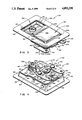
- FIG. 3 is a perspective view, on an enlarged scale, of the operating mechanism that is utilized with the locks of FIGS. 1 and 2, with the operating handle of the mechanism in its nested position, and with components of the operating mechanism being "locked,” and with the view showing principally front portions of the operating mechanism;
- FIG. 4 is a perspective view thereof, but showing principally rear portions of the operating mechanism
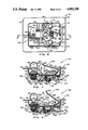
- FIG. 5 is a rear side elevational view thereof
- FIG. 6 is a sectional view as seen from a plane indicated by, a line 6--6 in FIG. 5;
- FIG. 7 is a bottom plan view thereof
- FIG. 8 is a rear side elevational view similar to FIG. 5 but with components of the mechanism being "unlocked” and with the handle being shown in an extended position;
- FIG. 9 is a sectional view as seen from a plane indicated by a line 9--9 in FIG. 8;
- FIG. 10 is a bottom plan view thereof
- FIG. 11 is a sectional view similar to FIG. 9, but with the view showing illustrating the positioning of components of the mechanism when the handle is between its nested and its operating positions;
- FIG. 12 is an exploded perspective view of selected components of the lock operating mechanism, with the view showing principally rear portions thereof;
- FIG. 13 is a front side elevational view, on an enlarged scale, of one of the latch bolt assemblies that is depicted in FIG. 2, together with portions of an associated strike and portions of a door frame on which the strike is mounted, with portions thereof broken away to permit underlying features to be seen; and,
- FIG. 14 is a perspective view similar to FIG. 3 but depicting an operating mechanism that does not feature a key-locking capability.
- the lock 50 includes an operating mechanism 100 that is located substantially “centrally” between a pair of relatively “remotely” located latch bolt mechanisms 90.
- FIG. 2 another embodiment of a plural-point flush type door lock that incorporates features of the preferred practice of the present invention is indicated generally by the numeral 50'.
- the lock 50' is identical to the lock 50 insofar as it includes the operating mechanism 100 at a central location between the latch bolt mechanisms 90.
- a pair of cables 80 flexibly connect the operating mechanism 100 with the latch bolt mechanisms 90 for selectively providing tension in directions that are indicated by arrows 81 for operating the latch bolt mechanisms 90 to retract latch bolts 94 that normally project from housings 92 of the latch bolt mechanisms 90, as will be explained.
- the lock embodiment 50' of FIG. 2 differs from the lock embodiment 50 of FIG.
- a pair of elongate rod members 80' are provided to rigidly interconnect the operating mechanism 100 with the latch bolt mechanisms 90 for selectively providing tension in directions that are indicated by arrows 81' for operating the latch bolt mechanisms 90 to retract the latch bolts 94.
- the latch bolt mechanisms 90 can take any of a variety of commercially available forms, including slide bolt assemblies such as are depicted in the referenced Multiple Bolt Patent or the referenced Multiple Slide Bolt Patent, or such slide bolt assemblies as are sold by the Eberhard Manufacturing Company division of The Eastern Company, Cleveland, Ohio 44136 under product designations 10-5597, 4974-52 or 5638U. Referring to FIG. 13, one of the latch bolt assemblies 90 that is utilized in the lock 50' of FIG. 2 is depicted as taking the form of Eberhard product 4974-52.
- the assembly 90 has a welded casing 92 that houses portions of a latch bolt 94.
- a compression coil spring 96 is carried within the confines of the casing 92 and biases the latch bolt 94 toward an extended position that is depicted in FIG. 13.
- the rod member 80' that connects with the depicted latch bolt assembly 90 functions in response to operation of the centrally located mechanism 100 to retract the latch bolt 94 (in the direction of the arrow 81') so that the latch bolt 94 will disengage a conventional strike 98 that is provided to latchingly receive the latch bolt 94 when the door on which the latch bolt assembly 90 is mounted is closed.
- the lock operating mechanism 100 is a key-controlled, paddle-handle, flush-mountable unit that is adapted to be supported on such structures as a swinging door (not shown) for relative movement therewith to bring the latch bolt assemblies 90 of such latch or lock units as the locks 50, 50' into and out of juxtaposition with suitably configured conventional strikes (such as the strike 98 that is depicted in FIG. 13).
- suitably configured conventional strikes such as the strike 98 that is depicted in FIG. 13
- a separate strike is associated with each of the latch assemblies 90 that are supported on a door frame or on other structure (not shown) that extends about the perimeter of the closed door.
- the manner in which locks of this general type are mounted on doors is well known to those skilled in the art, and is described and illustrated in such patents as the referenced Multiple Bolt Patent and the referenced Multiple Slide Bolt Patent.
- the operating mechanism 100 includes a pan-shaped housing 120 that nests and pivotally mounts a handle 220.
- the handle 220 is movable relative to the housing 120 between a normally nested position (shown in FIGS. 1, 3, 6 and 7) and an extended position (shown in FIGS. 9 and 10) to effect movement of a slide 180 along a linear track 160 that is defined by a mounting plate 150. Movement of the slide 180, in turn, effects counter-rotation of a pair of arms 270 (compare FIGS. 5 and 8) that are connected to the elongate linkage members 80 or 80' (see FIG. 2) to operate the latch bolt assemblies 90 of the lock 50 or 50'.
- the operating mechanism 100 that is depicted in FIGS. 3-11 is of a key-locking type, meaning that it includes a key operated locking device 300 that is mounted on the right back wall portion 126.
- the locking device 300 includes a cam member 302 that is movable between a locked position, shown in FIGS. 5 and 7, and an unlocked position, shown in FIGS. 8 and 9.
- the cam member 302 presents an obstacle to movement of the slide 180 from a first position (shown in FIGS. 3-7) to a second position (shown in FIGS. 8-10) when the cam member 302 is in its locked position.
- FIGS. 8 and 9 when the cam 302 is in its unlocked position, the slide 180 is free to move to its second position.
- the operating mechanism 100' that is depicted in FIG. 14 is identical to the operating mechanism 100 except that the operating mechanism 100' includes no key operated locking device 300, and the housing 120' includes no mounting hole 146 for mounting the locking device 300 therein.
- the operating mechanism 100' is said to be of a "lock” or “locking” type, while the operating mechanism 100' is said to be of a "latch” or “latching” type.
- the body 120 is a rectangular, pan-shaped metal stamping having a perimetrically extending mounting flange 122 which surrounds a forwardly facing recess 124.
- Left and right back wall portions 126, 128 (as viewed in FIGS. 3-12) define levels of different depths in opposite end portions of the recess 124.
- an inclined back wall portion 130 interconnects with left and right back wall portions 126, 128.
- Forwardly extending end walls 132 and side walls 134 connect the back wall portions 126, 128, 139 with the perimetrically extending mounting flange 122.
- FIGS. 6, 7 and 12 Other features of the body 120 include a pair of raised stop formations 136 (see FIGS. 6, 7 and 12) that are formed along opposite side regions of the right back wall portion 128, and a pair of dimple-like detent receiving formations 140, 142 (see FIGS. 6 and 12) that are formed in the right back wall portion 128 at spaced locations along the track 160.
- the stops 136 project into the recess 124 at locations that are near the side walls 134.
- the stops 136 are engaged by the handle 120 when the handle 120 is in its nested position.
- a pair of rivet holes 144 are formed through the right back wall portion 128 at locations that are between the rectangular opening 138 and each of the stops 136.
- a key-cylinder mounting hole 146 is formed through the left back wall portion 126. Opposite sides of the hole 146 have flat, parallel-extending surfaces 147. Aligned holes 148 are formed through the side walls 134 near their left ends.
- the mounting plate 150 has opposite side portions 152 that extend in a common plane and are arranged to extend in intimate contact with the right back wall portion 128 of the housing 120 to reinforce the back wall portion 128.
- the mounting plate 150 has a U-shaped, rearwardly-extending right end region 154, and an inclined, forwardly-extending left end region 156.
- a pair of opposed, rearwardly and inwardly turned rail formations 158 connect with the side portions 152 and cooperate with the right end formation 154 to define the track 160.
- a stop surface 162 is defined by the right end formation 154 near the right end of the track 160.
- a pair of rivet holes 164 are formed through the side portions 152 in alignment with the rivet holes 144.
- a pair of shoulder rivets 170 are provided for assembling several of the components of the locking mechanism 100.
- the rivets 170 each have a relatively large diameter portion 172, a relatively small diameter portion 174, and a shoulder 176 that forms a transition between the relatively large and small diameter portions 172, 174.
- the relatively large diameter portions 172 extend from headed ends 178 of the rivets 170 to the shoulders 176.
- the relatively small diameter portions 174 extend from the shoulders 176 to define the remainder of the lengths of the rivets 170.
- the relatively large diameter portions 172 are inserted through holes 272 that are formed in the arms 270, and through sleeves 282, whereafter (1) the relatively small diameter portions 174 are inserted through the rivet holes 164, 144 that are formed in the plate 150 and in the back wall portion 128, and (2) end regions of the small diameter portions 174 are swaged to provide flattened head formations 179 (see FIGS. 6, 9 and 11).
- the flattened head formations 179 overlie front surface portions of the back wall 128 and extend into the forwardly-facing recess 124 of the housing 120.
- the mounting plate 150 and the back wall portion 128 of the housing 120 are clamped tightly into overlying relationship between the shoulders 176 and the head formations 179; the relatively large diameter portions 172 of the rivets 170 are rigidly connected to the housing 120 and are caused to extend rearwardly from the mounting plate 150; and the arms 270 are mounted on the relatively large diameter portions 172 for pivotal movement relative to the housing 120 about the axes of the rivets 170.
- the arms 270 are not tightly clamped between the rivet heads 178 and the sleeves 282. Stated in another way, the ability of the arms 270 to pivot about the axes of the rivets 170 is not restricted by the swaging of the ends of the rivet portions 174 to provide the head formations 179, whereby the arms 270 remain free to pivot about the axes of the rivets 170.
- the slide 180 is a solid member which can be formed from plastics material as by injection molding techniques, or from metal utilizing conventional casting or powder metallurgy techniques.
- the slide 180 has a relatively large left end region 184 with a leftwardly projecting tab 186 that is arranged to overlie the cam member 302 when the key operated locking device 300 is "locked" (see FIGS. 4-7); a central region 188 that has about half the cross-sectional area of the left end region 184; and a rightwardly projecting tab 190 that is configured to extend alongside the right end formation 154 of the mounting plate 150 (see FIGS. 4 and 6).
- a pair of grooves 192 are formed along opposite sides of the slide 180 to receive the rail formations 158 of the mounting plate 150 to mount the slide 180 for linear movement along the track 160.
- the opening 182 that receives the handle projection 232 extends through the slide 180 near where the rightwardly extending tab 190 joins the central region 188.
- a closed-ended hole 194 is formed in the central region 186 and opens forwardly toward the back wall portion 128.
- a cylindrical projection 196 extends rearwardly from the central region 188 for establishing a pivotal connection with the arms 270, as will be explained.
- slide 180 includes the provision of a stop surface 198 that is engageable with the stop surface 162 on the mounting plate 150 to limit the extent of rightward movement of the slide 180 along the track 160, and the provision of a locking surface 200 that is defined by the left end region 184 of the slide 180 at a location that is forward with respect to the tab 186 (for engaging the cam 302 of the locking device 300, as will be explained).
- the slide 180 is movable along the track 160 between first and second positions.
- the first position of the slide 180 is a position that is assumed by the slide 180 when the handle 220 is nested, as is shown in FIGS. 5-7.
- the second position of the slide 180 is a position that is assumed by the slide 180 when the handle 220 is extended, as is shown in FIGS. 8-10.
- the exact locations of the slide 180 relative to the housing 120 when the slide 180 is in its first and second positions is determined in part by the locations of the closed-ended hole 194 and the dimple-like depressions 140, 142, for, as will be explained, the operation of the detent 250 is governed by the locations of the three formations 140, 142, 194.
- the paddle handle 220 is a sheet metal stamping having a generally rectangular, substantially flat plate portion 222 and a pair of opposed, inwardly-turned side flanges 224.
- An outwardly-turned gripping flange 228 is provided at the left end of the handle 220 (as viewed in FIGS. 3-12), and an inwardly-turned operating flange 230 is provided at the right end.
- the projecting portion 232 that extends through the back wall opening 138 and into the slide formation 182 is formed as an integral part of the operating flange 230.
- the handle 22 has aligned mounting holes 233 formed through its side flanges 224.
- a headed pin 236 extends through the housing holes 148 and through the handle mounting holes 233 to pivotally mount the handle 220 on the housing 120 at a location between the housing's side walls 234. While the headed pin 236 can be swaged at both ends to retain it in position relative to the housing 120, fasteners such as the cotter pin 237 that is illustrated in FIGS. 7 and 10 also can be used to secure the pin 236 in place.
- the projecting formation 232 of the handle 220 is matingly received in a slip fit within the receiving formation 182 of the slide 180 such that there is a minimum of "play" therebetween, by which arrangement the handle 220 and the slide 180 are drivingly interconnected for smooth, play-free, concurrent movement.
- the slide 180 is releasably retained in its first and second positions relative to the housing 120 (as by a detent 250 that is shown in FIGS. 6, 7 and 9 that is interposed between the slide 180 and the housing 120, as will be explained)
- the handle 220 is likewise retained in its nested and extended positions, respectively, relative to the housing 120.
- the detent 250 includes a hardened steel ball 252 that is carried in a closed-ended passage 194 that is formed in the slide 180.
- a compression coil spring 254 is inserted into the passage 192 before the ball 252 is inserted, whereby the spring 254 operates to bias the ball 252 outwardly with respect to the passage 192 (i.e., in a direction that is "forward" with respect to the housing 120) so as to cause the ball 252 to engage the left back wall portion 128 of the housing 120.
- the slide 180 is in its first position (i.e., when the handle 220 is nested)
- the closed-ended hole 194 aligns with the depression 140 (see FIG.
- the detent ball 252 is received within the dimple-like depression 140 that is formed in the back wall portion 128.
- the slide 180 is in its second position (i.e., when the handle 220 is extended), the closed-ended hole 194 aligns with the depression 142 (see FIG. 9), and the detent ball 252 is received within the dimple-like depression 142 that is formed in the back wall portion 128.
- the operating arms 270 are of generally L-shaped configuration, with inwardly extending leg portions 274 and rightwardly extending leg portions 276 that join in the vicinity of the openings 272 that are formed through the arms 270 to receive the rivets 170.
- Slot-like elongate openings 278 are provided in overlapping portions of the inwardly extending legs 274 to receive the cylindrical formation 196 of the slide 180 therein--by which arrangement the arms 270 are caused to be counter-rotated about the axes of the rivets 170 in response to movement of the slide 180 between its first and second positions (i.e., the arms 270 pivot about the axes of the rivets 170 in opposite clockwise and counterclockwise directions so as to either pivot the leg portions 276 toward each other and toward the slide track 160, or to pivot the leg portions 276 relative away from each other and away from the slide track 160).
- Holes 280 are provided through the leg portions 276 near the rightwardly extending ends thereof to receive pins (not shown) that connect the operating arms 270 with the elongate linkage members 80 of the lock 50 (or the elongate linkage members 80' of the lock 50').
- the arms 270 are depicted in their normal, non-operating positions. Referring to FIGS. 8-10, the arms 270 are depicted in their operating positions wherein the arms 270 serve to move the elongate linkage members 80, 80' in directions that are indicated in FIGS. 1 and 2, respectively, by arrows 81, 81'.
- the key control device 300 includes a lock cylinder 310 into which a key 312 (see FIGS. 6, 7 and 9-11) may be inserted.
- the key 312 is configured to cooperate with tumblers (not shown) that are housed within the cylinder 310 to permit the cam locking member 302 to be rotated between its locked position (shown in FIGS. 2 and 4-7) and its unlocked position (shown in FIGS. 8-11).
- the cylinder 310 is provided with an enlarged head 320 and a threaded body 322.
- a pair of flats 324 are formed on opposite sides of the threaded body 322.
- a groove 326 extends perimetrically about the body 322 in the vicinity of the juncture of the body 322 with the head 320.
- the cylinder 310 is positioned with its head 320 engaging the forward surface of the left back wall portion 126 of the housing 120, with its body 322 extending through the hole 146 and with its flats 324 engaging the flat surfaces 147.
- the key locking control device 300 is of a conventional, commercially available type, it is selected from among various commercially available key controls which have particular operational characteristics. These operational characteristics should include key removal capability when the locking cam 302 is positioned in either of its locked and unlocked positions. Once the locking cam 302 has been positioned in either of its locked or unlocked positions and the key 312 has been removed from the cylinder 310, the key control 300 maintains the locking cam 302 in such position. When the cam member 302 is in its locked position, it extends into engagement (or nearly into engagement) with the locking formation 200 that is provided on the left end region of the slide 180 to prevent the slide 180 from moving out of its normal "first" position.
- the described combination and arrangement of operating mechanism components provides an operating mechanism 100 which comprises a relatively small number of parts, very few of which require precision machining.
- the detent system 250 releasably holds the slide 180 in position relative to the housing 120 and prevents the slide 180 from rattling in the presence of vibration.
- the detent system 250 also operates to releasably hold the handle 220 in each of its nested and extended positions. Also, the detent system 250 functions to assist in effecting final movement of the slide 180 to its first and second positions.
- the strong biasing action of the spring 254 will tend to project the ball 252 rapidly into the depression 140 or 142, thereby causing the slide 180 to move as is needed to permit maximum projection of the ball 252 into the depression 140 or 142.
- the leftwardly extending slide projection 186 overlies the locking cam 302 so as to prevent forcing and bending of the cam 302 which might permit unauthorized operation of the operating mechanism 100 when the key locking device 300 has oriented the cam 302 to "lock" the slide 180 against translation along the track 160.
Abstract
Description
Claims (20)
Priority Applications (1)
| Application Number | Priority Date | Filing Date | Title |
|---|---|---|---|
| US07/257,837 US4892338A (en) | 1988-10-13 | 1988-10-13 | Plural point door lock and flush-mountable operating mechanism with detent |
Applications Claiming Priority (1)
| Application Number | Priority Date | Filing Date | Title |
|---|---|---|---|
| US07/257,837 US4892338A (en) | 1988-10-13 | 1988-10-13 | Plural point door lock and flush-mountable operating mechanism with detent |
Publications (1)
| Publication Number | Publication Date |
|---|---|
| US4892338A true US4892338A (en) | 1990-01-09 |
Family
ID=22977965
Family Applications (1)
| Application Number | Title | Priority Date | Filing Date |
|---|---|---|---|
| US07/257,837 Expired - Lifetime US4892338A (en) | 1988-10-13 | 1988-10-13 | Plural point door lock and flush-mountable operating mechanism with detent |
Country Status (1)
| Country | Link |
|---|---|
| US (1) | US4892338A (en) |
Cited By (73)
| Publication number | Priority date | Publication date | Assignee | Title |
|---|---|---|---|---|
| US5042853A (en) * | 1990-06-06 | 1991-08-27 | Tri-Mark | Paddle latch assembly |
| FR2687428A1 (en) * | 1992-02-18 | 1993-08-20 | Bricard Sa | MULTI-POINT LOCK WITH SECONDARY PEN CONDAMNABLE INDEPENDENTLY FROM THE MAIN PIPE. |
| US5265450A (en) * | 1992-03-05 | 1993-11-30 | Pat Doyle | Latch handle lock for tailgates |
| US5413391A (en) * | 1993-07-12 | 1995-05-09 | Hartwell Corporation | Self-closing latch |
| WO1995013445A1 (en) * | 1993-11-09 | 1995-05-18 | Oskar Suomi Oy | Door locking mechanism |
| US5419167A (en) * | 1992-08-17 | 1995-05-30 | Takigen Manufacturing Co., Ltd. | Door grip assembly |
| US5439260A (en) * | 1993-10-29 | 1995-08-08 | The Eastern Company | Handle operable rotary latch and lock |
| US5586458A (en) * | 1993-10-29 | 1996-12-24 | The Eastern Company | Handle operable rotary latch and lock |
| US5586795A (en) * | 1993-03-01 | 1996-12-24 | Takigen Manufacturing Co. Ltd. | Embedded-type handle assembly |
| US5595076A (en) * | 1993-10-29 | 1997-01-21 | The Eastern Company | Handle operable two-point latch and lock |
| US5611224A (en) * | 1993-10-29 | 1997-03-18 | The Eastern Company | Handle operable rotary latch and lock |
| US5670025A (en) * | 1995-08-24 | 1997-09-23 | Saturn Machine & Welding Co., Inc. | Coke oven door with multi-latch sealing system |
| US5681066A (en) * | 1995-09-22 | 1997-10-28 | Hartwell Corporation | Two-point self-closing latch |
| US5820174A (en) * | 1997-04-18 | 1998-10-13 | Cleveland Hardware & Forging Company | Lockable slammable paddle latch |
| US5820175A (en) * | 1996-09-23 | 1998-10-13 | Hartwell Corporation | Self-closing latch |
| US5884948A (en) * | 1993-10-29 | 1999-03-23 | The Eastern Company | Rotary latch and lock |
| US5927773A (en) * | 1997-02-19 | 1999-07-27 | Tri/Mark Corporation | Latch assembly for movable closure |
| US6023953A (en) * | 1998-01-30 | 2000-02-15 | Southco, Inc. | Slam latch with opposing slides |
| US6086121A (en) * | 1998-04-02 | 2000-07-11 | Southco, Inc. | Rod roller system for multi-point latch |
| US6101853A (en) * | 1998-12-28 | 2000-08-15 | Monaco Coach Corporation | Door and latch mechanism |
| KR20000070002A (en) * | 1997-01-08 | 2000-11-25 | 스티븐 제이. 켈리 | Locking slide latch |
| US6231091B1 (en) * | 1998-06-09 | 2001-05-15 | Tri/Mark Corporation | Control mechanism for operating a latch |
| US6354638B1 (en) * | 1997-09-26 | 2002-03-12 | Emka Beschlagteile Gmbh & Co Kg | Bar-shaped closure with operating travel moving away from the door leaf |
| US6357806B1 (en) * | 1998-11-13 | 2002-03-19 | Jamco Corporation | Door latch device |
| US6427500B1 (en) | 1998-11-09 | 2002-08-06 | The Eastern Company | Latch, lock and hinge system for use with closures such as tonneau covers |
| US6490895B1 (en) * | 1999-01-12 | 2002-12-10 | The Eastern Company | Versatile paddle handle operating mechanism for latches and locks |
| EP1270854A1 (en) * | 2001-06-29 | 2003-01-02 | Justrite Manufacturing Company, L.L.C. | Safety cabinet with improved latch and handle |
| US20030020287A1 (en) * | 2001-07-10 | 2003-01-30 | Knorr-Bremse Ag | Commercial vehicle, rail or bus vehicle entry door |
| US20030227239A1 (en) * | 2002-06-05 | 2003-12-11 | Chih-Chung Wang | Lockable bezel |
| US6666053B2 (en) | 2001-12-19 | 2003-12-23 | Randall C. Hansen | Reversible spring-loaded lock slide |
| US20040066122A1 (en) * | 2002-10-04 | 2004-04-08 | Justrite Manufacturing Company Llc | Aerosol container storage cabinet |
| US6758503B2 (en) | 2001-12-19 | 2004-07-06 | Randall C. Hansen | Paddle lock having slim profile |
| US20040177443A1 (en) * | 2002-09-06 | 2004-09-16 | Scott Simmonds | Bed siderail having a latch |
| US20040222647A1 (en) * | 2003-05-07 | 2004-11-11 | Smith Kelly K. | Low profile mechanical assist hood latch |
| US6899362B1 (en) | 1999-10-28 | 2005-05-31 | The Eastern Company | Linkage assembly for operating one or more latches |
| US6957979B2 (en) | 2001-06-01 | 2005-10-25 | Southco, Inc. | Latch with bail-type mounting |
| US20060082161A1 (en) * | 2004-10-18 | 2006-04-20 | Minix C R | Push button latch release assembly |
| US7040675B1 (en) | 2003-02-12 | 2006-05-09 | The Eastern Company | Linkage operated latching system |
| US20060137275A1 (en) * | 2004-12-17 | 2006-06-29 | Eran Vashdi | Safety device |
| US20070273158A1 (en) * | 2006-05-16 | 2007-11-29 | Securitech Group, Inc. | Multi-point exit door lock and method of installation |
| US20080099160A1 (en) * | 2006-11-01 | 2008-05-01 | Chin-Fu Chen | Regulation structure for shutter slats |
| US20080106174A1 (en) * | 2006-11-06 | 2008-05-08 | Justrite Manufacturing Company | Safety cabinet |
| US20080148790A1 (en) * | 2006-12-22 | 2008-06-26 | C. R. Laurence Company, Inc. | Door lock system and method |
| US7398664B1 (en) | 2005-03-14 | 2008-07-15 | The Eastern Company | Handle and housing assembly |
| US7454933B1 (en) | 2005-03-14 | 2008-11-25 | The Eastern Company | Handle and housing assembly |
| US20090014590A1 (en) * | 2007-07-09 | 2009-01-15 | Airbus France | Hatch equipped with at least one locking socket capable of being actuated on each side of the hatch |
| US7526933B2 (en) | 2006-10-18 | 2009-05-05 | Master Lock Company Llc | Multipoint door lock |
| US20090113955A1 (en) * | 2007-11-06 | 2009-05-07 | Blumcraft Of Pittsburgh | Deadbolt device for a door |
| US20090146449A1 (en) * | 2007-12-07 | 2009-06-11 | Steffens Enterprises, Inc. | Folding cargo bay cover for pickup truck |
| WO2009087692A2 (en) | 2007-12-19 | 2009-07-16 | Cisa S.P.A. | Antipanic kit for doors |
| US20110126598A1 (en) * | 2009-11-30 | 2011-06-02 | Bacon Bruce C | Remotely operated locking paddle handle latch assembly for closures and the like |
| US20110181055A1 (en) * | 2010-01-26 | 2011-07-28 | Trimark Corporation | Free floating paddle handle for vehicle doors |
| US20120272695A1 (en) * | 2011-04-27 | 2012-11-01 | Trimark Corporation | Door handle assembly for vehicle compartment |
| US20120319411A1 (en) * | 2009-11-30 | 2012-12-20 | Mueller Matthias | Cabinet latch |
| US8393187B2 (en) | 2008-12-22 | 2013-03-12 | Bauer Products, Inc. | Remotely operated locking paddle handle latch assembly |
| US8465062B2 (en) | 2007-08-20 | 2013-06-18 | The Eastern Company | Armored vehicle door hardware providing access, egress, rescue and security |
| US20130214544A1 (en) * | 2012-02-20 | 2013-08-22 | Kung-Cheng Chen | One hand operable cabinet latch |
| US8621901B2 (en) | 2010-07-20 | 2014-01-07 | Bauer Products, Inc. | Lock system for vehicles and the like |
| US20140110953A1 (en) * | 2012-10-23 | 2014-04-24 | Stéfane Leib | Horizontal latch operating system |
| US9085919B2 (en) | 2008-12-22 | 2015-07-21 | Bauer Products, Inc. | Touch pad lock assembly |
| US20170009489A1 (en) * | 2012-12-07 | 2017-01-12 | Capitol Development Llc | Locking system with multiple latches |
| US9630036B2 (en) | 2012-02-01 | 2017-04-25 | Justrite Manufacturing Company Llc | Safety cabinet with interlock mechanism |
| WO2017127774A3 (en) * | 2016-01-22 | 2017-09-08 | Centrix Aero, LLC | Bin latch system |
| US9814311B2 (en) | 2012-02-08 | 2017-11-14 | Justrite Manufacturing Company, Llc | Safety cabinet with sequential door-closing system |
| US9940767B2 (en) | 2008-12-22 | 2018-04-10 | Bauer Products, Inc. | Touch pad lock assembly |
| US10005510B2 (en) * | 2014-01-07 | 2018-06-26 | Honda Motor Co., Ltd. | Saddle bag lock device for saddle-ride type vehicle |
| US10246914B2 (en) * | 2012-03-21 | 2019-04-02 | Schlage Lock Company Llc | Two point lock for bi-fold windows and doors |
| US10378237B2 (en) | 2008-12-22 | 2019-08-13 | Bauer Products, Inc. | Touch pad lock assembly with clutch system |
| US20190315259A1 (en) * | 2018-04-12 | 2019-10-17 | Hyundai Motor Company | Console apparatus with variable table |
| US20200283119A1 (en) * | 2019-03-06 | 2020-09-10 | Bell Helicopter Textron Inc. | Aircraft Door Structure |
| US20210230908A1 (en) * | 2018-05-24 | 2021-07-29 | Hawa Sliding Solutions Ag | Lock, fitting, strike plate and closing device for sliding doors and sliding door system |
| US11351846B2 (en) * | 2018-05-31 | 2022-06-07 | Oakmoore Pty Ltd | Lock system for a roll cover |
| EP4290036A1 (en) * | 2022-06-09 | 2023-12-13 | B/E Aerospace, Inc. | Integrated door lock for an aircraft galley container |
Citations (6)
| Publication number | Priority date | Publication date | Assignee | Title |
|---|---|---|---|---|
| US1593435A (en) * | 1923-05-24 | 1926-07-20 | Louis E Carter | Lock mechanism |
| US2560459A (en) * | 1947-09-10 | 1951-07-10 | Briggs Mfg Co | Locking mechanism for convertible tops |
| US4138869A (en) * | 1977-09-26 | 1979-02-13 | The Eastern Company | Self-locking key-controlled door lock |
| US4320642A (en) * | 1979-12-28 | 1982-03-23 | The Eastern Company | Paddle locks with handle disconnect features |
| US4321812A (en) * | 1979-12-28 | 1982-03-30 | The Eastern Company | Paddle lock with pivotally mounted handle disconnect member |
| US4438964A (en) * | 1981-06-18 | 1984-03-27 | Pierce Manufacturing, Inc. | Paddle operated vehicle latch |
-
1988
- 1988-10-13 US US07/257,837 patent/US4892338A/en not_active Expired - Lifetime
Patent Citations (6)
| Publication number | Priority date | Publication date | Assignee | Title |
|---|---|---|---|---|
| US1593435A (en) * | 1923-05-24 | 1926-07-20 | Louis E Carter | Lock mechanism |
| US2560459A (en) * | 1947-09-10 | 1951-07-10 | Briggs Mfg Co | Locking mechanism for convertible tops |
| US4138869A (en) * | 1977-09-26 | 1979-02-13 | The Eastern Company | Self-locking key-controlled door lock |
| US4320642A (en) * | 1979-12-28 | 1982-03-23 | The Eastern Company | Paddle locks with handle disconnect features |
| US4321812A (en) * | 1979-12-28 | 1982-03-30 | The Eastern Company | Paddle lock with pivotally mounted handle disconnect member |
| US4438964A (en) * | 1981-06-18 | 1984-03-27 | Pierce Manufacturing, Inc. | Paddle operated vehicle latch |
Cited By (103)
| Publication number | Priority date | Publication date | Assignee | Title |
|---|---|---|---|---|
| US5042853A (en) * | 1990-06-06 | 1991-08-27 | Tri-Mark | Paddle latch assembly |
| FR2687428A1 (en) * | 1992-02-18 | 1993-08-20 | Bricard Sa | MULTI-POINT LOCK WITH SECONDARY PEN CONDAMNABLE INDEPENDENTLY FROM THE MAIN PIPE. |
| EP0557183A1 (en) * | 1992-02-18 | 1993-08-25 | Bricard S.A. | Multipoint lock with secondary bolts being operable independently from the main bolt |
| US5265450A (en) * | 1992-03-05 | 1993-11-30 | Pat Doyle | Latch handle lock for tailgates |
| US5419167A (en) * | 1992-08-17 | 1995-05-30 | Takigen Manufacturing Co., Ltd. | Door grip assembly |
| US5586795A (en) * | 1993-03-01 | 1996-12-24 | Takigen Manufacturing Co. Ltd. | Embedded-type handle assembly |
| US5413391A (en) * | 1993-07-12 | 1995-05-09 | Hartwell Corporation | Self-closing latch |
| US5884948A (en) * | 1993-10-29 | 1999-03-23 | The Eastern Company | Rotary latch and lock |
| US5439260A (en) * | 1993-10-29 | 1995-08-08 | The Eastern Company | Handle operable rotary latch and lock |
| US5564295A (en) * | 1993-10-29 | 1996-10-15 | The Eastern Company | Handle operable rotary latch and lock |
| US5586458A (en) * | 1993-10-29 | 1996-12-24 | The Eastern Company | Handle operable rotary latch and lock |
| US5595076A (en) * | 1993-10-29 | 1997-01-21 | The Eastern Company | Handle operable two-point latch and lock |
| US5611224A (en) * | 1993-10-29 | 1997-03-18 | The Eastern Company | Handle operable rotary latch and lock |
| WO1995013445A1 (en) * | 1993-11-09 | 1995-05-18 | Oskar Suomi Oy | Door locking mechanism |
| US5670025A (en) * | 1995-08-24 | 1997-09-23 | Saturn Machine & Welding Co., Inc. | Coke oven door with multi-latch sealing system |
| US5681066A (en) * | 1995-09-22 | 1997-10-28 | Hartwell Corporation | Two-point self-closing latch |
| US5820175A (en) * | 1996-09-23 | 1998-10-13 | Hartwell Corporation | Self-closing latch |
| KR20000070002A (en) * | 1997-01-08 | 2000-11-25 | 스티븐 제이. 켈리 | Locking slide latch |
| US5927773A (en) * | 1997-02-19 | 1999-07-27 | Tri/Mark Corporation | Latch assembly for movable closure |
| US5820174A (en) * | 1997-04-18 | 1998-10-13 | Cleveland Hardware & Forging Company | Lockable slammable paddle latch |
| US6354638B1 (en) * | 1997-09-26 | 2002-03-12 | Emka Beschlagteile Gmbh & Co Kg | Bar-shaped closure with operating travel moving away from the door leaf |
| US6023953A (en) * | 1998-01-30 | 2000-02-15 | Southco, Inc. | Slam latch with opposing slides |
| US6086121A (en) * | 1998-04-02 | 2000-07-11 | Southco, Inc. | Rod roller system for multi-point latch |
| US6231091B1 (en) * | 1998-06-09 | 2001-05-15 | Tri/Mark Corporation | Control mechanism for operating a latch |
| US6427500B1 (en) | 1998-11-09 | 2002-08-06 | The Eastern Company | Latch, lock and hinge system for use with closures such as tonneau covers |
| US6357806B1 (en) * | 1998-11-13 | 2002-03-19 | Jamco Corporation | Door latch device |
| US6101853A (en) * | 1998-12-28 | 2000-08-15 | Monaco Coach Corporation | Door and latch mechanism |
| US6490895B1 (en) * | 1999-01-12 | 2002-12-10 | The Eastern Company | Versatile paddle handle operating mechanism for latches and locks |
| US6899362B1 (en) | 1999-10-28 | 2005-05-31 | The Eastern Company | Linkage assembly for operating one or more latches |
| US6957979B2 (en) | 2001-06-01 | 2005-10-25 | Southco, Inc. | Latch with bail-type mounting |
| EP1270854A1 (en) * | 2001-06-29 | 2003-01-02 | Justrite Manufacturing Company, L.L.C. | Safety cabinet with improved latch and handle |
| US6729701B2 (en) | 2001-06-29 | 2004-05-04 | Justrite Manufacturing Company Llc | Safety cabinet |
| US20030020287A1 (en) * | 2001-07-10 | 2003-01-30 | Knorr-Bremse Ag | Commercial vehicle, rail or bus vehicle entry door |
| US6729675B2 (en) * | 2001-07-10 | 2004-05-04 | Knorr-Bremse Systeme Fur Schienenfahrzeuge Gmbh | Commercial vehicle, rail or bus vehicle entry door |
| US6666053B2 (en) | 2001-12-19 | 2003-12-23 | Randall C. Hansen | Reversible spring-loaded lock slide |
| US6758503B2 (en) | 2001-12-19 | 2004-07-06 | Randall C. Hansen | Paddle lock having slim profile |
| US6729662B2 (en) * | 2002-06-05 | 2004-05-04 | Quanta Computer, Inc. | Lockable bezel |
| US20030227239A1 (en) * | 2002-06-05 | 2003-12-11 | Chih-Chung Wang | Lockable bezel |
| US20040177443A1 (en) * | 2002-09-06 | 2004-09-16 | Scott Simmonds | Bed siderail having a latch |
| US7073220B2 (en) * | 2002-09-06 | 2006-07-11 | Hill-Rom Services, Inc. | Bed siderail having a latch |
| US20040066122A1 (en) * | 2002-10-04 | 2004-04-08 | Justrite Manufacturing Company Llc | Aerosol container storage cabinet |
| US7040675B1 (en) | 2003-02-12 | 2006-05-09 | The Eastern Company | Linkage operated latching system |
| US20040222647A1 (en) * | 2003-05-07 | 2004-11-11 | Smith Kelly K. | Low profile mechanical assist hood latch |
| US20080061563A1 (en) * | 2003-05-07 | 2008-03-13 | Hewlett-Packard Development Company, L.P. | Low profile mechanical assist hood latch |
| US7614672B2 (en) | 2003-05-07 | 2009-11-10 | Hewlett-Packard Development Company, L.P. | Low profile mechanical assist hood latch |
| US7325846B2 (en) | 2003-05-07 | 2008-02-05 | Hewlett-Packard Development Company, L.P. | Low profile mechanical assist hood latch |
| US20060082161A1 (en) * | 2004-10-18 | 2006-04-20 | Minix C R | Push button latch release assembly |
| US7261328B2 (en) | 2004-10-18 | 2007-08-28 | Fastec Industrial Corp. | Push button latch release assembly |
| US20060137275A1 (en) * | 2004-12-17 | 2006-06-29 | Eran Vashdi | Safety device |
| US7398664B1 (en) | 2005-03-14 | 2008-07-15 | The Eastern Company | Handle and housing assembly |
| US7454933B1 (en) | 2005-03-14 | 2008-11-25 | The Eastern Company | Handle and housing assembly |
| US8052182B1 (en) | 2005-03-14 | 2011-11-08 | The Eastern Company | Handle and housing assembly with skirted seal |
| US7748246B1 (en) | 2005-03-14 | 2010-07-06 | The Eastern Company | Handle and housing assembly |
| US9074392B2 (en) * | 2006-05-16 | 2015-07-07 | Securitech Group, Inc. | Multi-point exit door lock and method of installation |
| US20070273158A1 (en) * | 2006-05-16 | 2007-11-29 | Securitech Group, Inc. | Multi-point exit door lock and method of installation |
| US20090193860A1 (en) * | 2006-10-18 | 2009-08-06 | Master Lock Company Llc | Multipoint door lock |
| US7526933B2 (en) | 2006-10-18 | 2009-05-05 | Master Lock Company Llc | Multipoint door lock |
| US20080099160A1 (en) * | 2006-11-01 | 2008-05-01 | Chin-Fu Chen | Regulation structure for shutter slats |
| US20080106174A1 (en) * | 2006-11-06 | 2008-05-08 | Justrite Manufacturing Company | Safety cabinet |
| US9309696B2 (en) | 2006-12-22 | 2016-04-12 | C.R. Laurence Company, Inc. | Door lock system and method |
| US20080148790A1 (en) * | 2006-12-22 | 2008-06-26 | C. R. Laurence Company, Inc. | Door lock system and method |
| US20090014590A1 (en) * | 2007-07-09 | 2009-01-15 | Airbus France | Hatch equipped with at least one locking socket capable of being actuated on each side of the hatch |
| US8100363B2 (en) * | 2007-07-09 | 2012-01-24 | Airbus Operations Sas | Hatch equipped with at least one locking socket capable of being actuated on each side of the hatch |
| US8844982B2 (en) | 2007-08-20 | 2014-09-30 | The Eastern Company | Armored vehicle door hardware providing access, egress, rescue and security |
| US8465062B2 (en) | 2007-08-20 | 2013-06-18 | The Eastern Company | Armored vehicle door hardware providing access, egress, rescue and security |
| US20090113955A1 (en) * | 2007-11-06 | 2009-05-07 | Blumcraft Of Pittsburgh | Deadbolt device for a door |
| US7849718B2 (en) * | 2007-11-06 | 2010-12-14 | C.R. Laurence Company, Inc. | Deadbolt device for a door |
| US8205928B2 (en) | 2007-12-07 | 2012-06-26 | Steffans Enterprises, Inc. | Folding cargo bay cover for pickup truck |
| US20090146449A1 (en) * | 2007-12-07 | 2009-06-11 | Steffens Enterprises, Inc. | Folding cargo bay cover for pickup truck |
| US7735881B2 (en) * | 2007-12-07 | 2010-06-15 | Steffens Enterprises, Inc. | Folding cargo bay cover for pickup truck |
| US20100219658A1 (en) * | 2007-12-07 | 2010-09-02 | Steffens Enterprises, Inc. | Folding cargo bay cover for pickup truck |
| CN101903609B (en) * | 2007-12-19 | 2013-02-27 | 西莎股份公司 | Antipanic kit for doors |
| WO2009087692A2 (en) | 2007-12-19 | 2009-07-16 | Cisa S.P.A. | Antipanic kit for doors |
| WO2009087692A3 (en) * | 2007-12-19 | 2009-11-12 | Cisa S.P.A. | Antipanic kit for doors |
| RU2471052C2 (en) * | 2007-12-19 | 2012-12-27 | Чиза С.П.А. | Set of evacuation exit for doors |
| US9085919B2 (en) | 2008-12-22 | 2015-07-21 | Bauer Products, Inc. | Touch pad lock assembly |
| US10378237B2 (en) | 2008-12-22 | 2019-08-13 | Bauer Products, Inc. | Touch pad lock assembly with clutch system |
| US8393187B2 (en) | 2008-12-22 | 2013-03-12 | Bauer Products, Inc. | Remotely operated locking paddle handle latch assembly |
| US9940767B2 (en) | 2008-12-22 | 2018-04-10 | Bauer Products, Inc. | Touch pad lock assembly |
| US20110126598A1 (en) * | 2009-11-30 | 2011-06-02 | Bacon Bruce C | Remotely operated locking paddle handle latch assembly for closures and the like |
| US8186191B2 (en) * | 2009-11-30 | 2012-05-29 | Bauer Products, Inc. | Remotely operated locking paddle handle latch assembly for closures and the like |
| US20120319411A1 (en) * | 2009-11-30 | 2012-12-20 | Mueller Matthias | Cabinet latch |
| US8579337B2 (en) * | 2010-01-26 | 2013-11-12 | Trimark Corporation | Free floating paddle handle for vehicle doors |
| US20110181055A1 (en) * | 2010-01-26 | 2011-07-28 | Trimark Corporation | Free floating paddle handle for vehicle doors |
| US8621901B2 (en) | 2010-07-20 | 2014-01-07 | Bauer Products, Inc. | Lock system for vehicles and the like |
| US20120272695A1 (en) * | 2011-04-27 | 2012-11-01 | Trimark Corporation | Door handle assembly for vehicle compartment |
| US9816299B2 (en) * | 2011-04-27 | 2017-11-14 | Trimark Corporation | Door handle assembly for vehicle compartment |
| US9630036B2 (en) | 2012-02-01 | 2017-04-25 | Justrite Manufacturing Company Llc | Safety cabinet with interlock mechanism |
| US9814311B2 (en) | 2012-02-08 | 2017-11-14 | Justrite Manufacturing Company, Llc | Safety cabinet with sequential door-closing system |
| US20130214544A1 (en) * | 2012-02-20 | 2013-08-22 | Kung-Cheng Chen | One hand operable cabinet latch |
| US10246914B2 (en) * | 2012-03-21 | 2019-04-02 | Schlage Lock Company Llc | Two point lock for bi-fold windows and doors |
| US20140110953A1 (en) * | 2012-10-23 | 2014-04-24 | Stéfane Leib | Horizontal latch operating system |
| US20170009489A1 (en) * | 2012-12-07 | 2017-01-12 | Capitol Development Llc | Locking system with multiple latches |
| US10655364B2 (en) * | 2012-12-07 | 2020-05-19 | Capitol Development, Llc | Locking system with multiple latches |
| US11643846B2 (en) | 2012-12-07 | 2023-05-09 | Capital Development, Llc | Locking system with multiple latches |
| US10005510B2 (en) * | 2014-01-07 | 2018-06-26 | Honda Motor Co., Ltd. | Saddle bag lock device for saddle-ride type vehicle |
| WO2017127774A3 (en) * | 2016-01-22 | 2017-09-08 | Centrix Aero, LLC | Bin latch system |
| US20190315259A1 (en) * | 2018-04-12 | 2019-10-17 | Hyundai Motor Company | Console apparatus with variable table |
| US11225182B2 (en) * | 2018-04-12 | 2022-01-18 | Hyundai Motor Company | Console apparatus with variable table |
| US20210230908A1 (en) * | 2018-05-24 | 2021-07-29 | Hawa Sliding Solutions Ag | Lock, fitting, strike plate and closing device for sliding doors and sliding door system |
| US11351846B2 (en) * | 2018-05-31 | 2022-06-07 | Oakmoore Pty Ltd | Lock system for a roll cover |
| US20200283119A1 (en) * | 2019-03-06 | 2020-09-10 | Bell Helicopter Textron Inc. | Aircraft Door Structure |
| EP4290036A1 (en) * | 2022-06-09 | 2023-12-13 | B/E Aerospace, Inc. | Integrated door lock for an aircraft galley container |
Similar Documents
| Publication | Publication Date | Title |
|---|---|---|
| US4892338A (en) | Plural point door lock and flush-mountable operating mechanism with detent | |
| US4683736A (en) | Cabinet lock with recessed handle | |
| US4320642A (en) | Paddle locks with handle disconnect features | |
| US4309884A (en) | Paddle lock with guard-protected handle disconnect member | |
| US4706478A (en) | Rotary handle operated door lock | |
| US4321812A (en) | Paddle lock with pivotally mounted handle disconnect member | |
| US4312202A (en) | Paddle lock with bolt-carried handle disconnect member | |
| US7748246B1 (en) | Handle and housing assembly | |
| US4335595A (en) | Paddle lock with handle disconnect | |
| US4231597A (en) | Flush-type door lock | |
| US6543821B1 (en) | Slam capable latch and lock system | |
| US4735447A (en) | Three-part vehicle-door latch | |
| US6264252B1 (en) | Multi-point sliding door latch | |
| US6755449B2 (en) | Locking system and components thereof | |
| US4911487A (en) | Rotary paddle latch | |
| US4138869A (en) | Self-locking key-controlled door lock | |
| US5586458A (en) | Handle operable rotary latch and lock | |
| US6513353B1 (en) | Lockable paddle handle with disconnect feature for operating remotely located latches | |
| US4312203A (en) | Flush-mountable lock with actuator disconnect feature | |
| CA1235452A (en) | Cabinet lock with recessed handle | |
| US6196599B1 (en) | Push/pull door latch | |
| US4850208A (en) | Latch and lock assemblies with spring-biased pivot bolts | |
| US5308128A (en) | Vehicle door latch | |
| US4986576A (en) | Locking door latch | |
| US4413849A (en) | Tool-operated flush-mountable latch |
Legal Events
| Date | Code | Title | Description |
|---|---|---|---|
| AS | Assignment |
Owner name: EASTERN COMPANY, 21944 DRAKE RD., CLEVELAND, OH 44 Free format text: ASSIGNMENT OF ASSIGNORS INTEREST.;ASSIGNOR:WEINERMAN, LEE S.;REEL/FRAME:004995/0141 Effective date: 19881013 |
|
| AS | Assignment |
Owner name: EASTERN COMPANY, THE, 21944 DRAKE ROAD, CLEVELAND, Free format text: ASSIGNMENT OF ASSIGNORS INTEREST.;ASSIGNORS:WEINERMAN, LEE S.;SPINELLI, JOSEPH P. JR.;RACHOCKI, MICHAEL J.;REEL/FRAME:004984/0029;SIGNING DATES FROM 19881130 TO 19881202 Owner name: EASTERN COMPANY, THE, A CT. CORP., OHIO Free format text: ASSIGNMENT OF ASSIGNORS INTEREST;ASSIGNORS:WEINERMAN, LEE S.;SPINELLI, JOSEPH P. JR.;RACHOCKI, MICHAEL J.;SIGNING DATES FROM 19881130 TO 19881202;REEL/FRAME:004984/0029 |
|
| STCF | Information on status: patent grant |
Free format text: PATENTED CASE |
|
| FPAY | Fee payment |
Year of fee payment: 4 |
|
| FPAY | Fee payment |
Year of fee payment: 8 |
|
| FEPP | Fee payment procedure |
Free format text: PAYOR NUMBER ASSIGNED (ORIGINAL EVENT CODE: ASPN); ENTITY STATUS OF PATENT OWNER: LARGE ENTITY |
|
| FPAY | Fee payment |
Year of fee payment: 12 |