US4889437A - Ticket issuing machines - Google Patents
Ticket issuing machines Download PDFInfo
- Publication number
- US4889437A US4889437A US07/219,798 US21979888A US4889437A US 4889437 A US4889437 A US 4889437A US 21979888 A US21979888 A US 21979888A US 4889437 A US4889437 A US 4889437A
- Authority
- US
- United States
- Prior art keywords
- circuit board
- information
- ticket issuing
- machine
- board module
- Prior art date
- Legal status (The legal status is an assumption and is not a legal conclusion. Google has not performed a legal analysis and makes no representation as to the accuracy of the status listed.)
- Expired - Fee Related
Links
Images


Classifications
-
- G—PHYSICS
- G07—CHECKING-DEVICES
- G07B—TICKET-ISSUING APPARATUS; FARE-REGISTERING APPARATUS; FRANKING APPARATUS
- G07B1/00—Machines for printing and issuing tickets
-
- G—PHYSICS
- G06—COMPUTING; CALCULATING OR COUNTING
- G06Q—INFORMATION AND COMMUNICATION TECHNOLOGY [ICT] SPECIALLY ADAPTED FOR ADMINISTRATIVE, COMMERCIAL, FINANCIAL, MANAGERIAL OR SUPERVISORY PURPOSES; SYSTEMS OR METHODS SPECIALLY ADAPTED FOR ADMINISTRATIVE, COMMERCIAL, FINANCIAL, MANAGERIAL OR SUPERVISORY PURPOSES, NOT OTHERWISE PROVIDED FOR
- G06Q30/00—Commerce
- G06Q30/02—Marketing; Price estimation or determination; Fundraising
- G06Q30/0283—Price estimation or determination
- G06Q30/0284—Time or distance, e.g. usage of parking meters or taximeters
Definitions
- This invention has reference to ticket issuing machines and has particular but not exclusive reference to tickets to be issued for travel by public transport more especially by omnibus or by railway.
- variable data to be printed on the ticket could relate to the kind of ticket (single, return period); the fare stage (either the stage of boarding or the stage at which the passenger was required to alight), the value of the ticket issued etc.
- static information was printed on the ticket and this information might refer to the issuing authority and the sequence of the ticket and perhaps the date of issue of the ticket.
- ticket machines included registers to enable accumulative information, such as the total number of tickets or the total value of tickets issued during a predetermined period to be displayed.
- Such registers usually showed an accumulative number which was checked as the conductor was issued with the ticket issuing machine at the start of a duty period and was rechecked at the end of the duty period also some ticket issuing machines were provided to issue preprinted tickets of predetermined denominations.
- a series of webs of tickets were arranged in a machine each web being printed in a distinctive colour and each representing a certain ticket value on depression of a selected lever a single ticket of a predetermined value (depending upon which lever was depressed) was issued.
- the machine also included counter mechanisms to indicate the number of tickets of each value issued.
- the amount of information which could be printed on the ticket or displayed on counter mechanisms was limited by the number of print wheels or display wheels which could be arranged in the ticket issuing machine as well as by the number of items which could be accommodated on each of the print wheels or display wheels.
- Ticket Issuing Machine for issuing tickets for totalizator betting applications and this machine includes a wire printer mechanism as well as a keyboard, a microprocessor and a matrix display.
- a ticket issuing machine for transport undertakings and which comprise a ticket printing device a paper feed device for feeding a ticket web past the printing device, a microprocessor means, a keyboard for entering data into the microprocessor means, a store for retaining information about information to be printed on a ticket which information can be transferred to the microprocessor means to control the ticket printing device under the control of the microprocessor means to determine the information to be printed on the ticket web, and a display panel for displaying information to be entered on the keyboard and information to be printed on the ticket and power means for driving the parts of the ticket issuing machine.
- a ticket issuing machine system includes a keyboard to enter into the machine details of a ticket to be issued, a printer to print out ticket information on the ticket depending on the data entered into the keyboard and means for storing information about the tickets issued by the machine characterised by the provision of a store circuit board module capable of storing data about the tickets issued and which is readily capable of being inserted into and removed from the machine to have the details of the tickets issued transferred to an exterior store.
- the ticket issuing machine and the store circuit board module each have an optical emitting means and an optical responsive means to enable signals about the tickets issued to be passed from the ticket issuing machine to the store circuit board module and vice versa.
- the optical emitting means comprises an infra red light emitter and the optical responsive means comprises an infra red light receiver.
- the ticket issuing machine system includes a recorder to enable details of tickets issued and recorded on the store circuit board module to be processed and recorded.
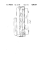
- FIG. 1 is a side view of the Ticket Issuing Machine simplified with top cover removed
- FIG. 2 is a simplified plan view of the ticket issuing machine with the cover keyboard and display and processor circuit board removed
- FIG. 3 is a sectional/front view of the machine with cover removed
- FIG. 4 is a detailed plan/view of the store circuit board and module compartment of the ticket issuing machine
- FIG. 5 is a front view of the compartment of FIG. 4
- FIG. 6 is a simplified circuit diagram of the store circuit board module
- FIG. 7 is a circuit diagram of part of the interface circuit between the store circuit board module and the ticket issuing machine
- FIGS. 1, 2 and 3 of the drawings there is shown a Ticket Issuing Machine suitable for use with a Transport undertaking for example for use on an omnibus when the machine is secured to a counter adjacent to the omnibus driver.
- the Machine includes a Print Unit 1 mounted at the rear of the machine and having two print rollers 2 and 3 (FIG. 2) each having an associated needle print head located/beneath the web guide 4 and web feed means for feeding a ticket web through the printer unit and which are conveniently of the kind described in the specification of our British Patent No. 2058674.
- a keyboard 6 (FIG. 1) is mounted on the upper front part of the machine and a display unit is associated with the keyboard and is arranged to display data entered into the machine (referring for example to the kind of ticket or the value of ticket to be issued) It also displays information or instructions about the kind of data next required to be entered into the machine.
- the ticket issuing machine is a microprocessor type of ticket issuing machine of the kind described in the Specification of European Patent application No. 0057080/and British Patent No. 2140952 on which the keyboard is operated to effect certain control functions. First of all the driver of the vehicle enters his code number into the machine and any other additional information about the time of start of his shift, the route number of his omnibus etc.
- a series of cable assembly terminals 7 are arranged in the machine with connections to and from the processor board 8 (FIG. 3) and the power board 9 which boards 8 and 9 are connected by a ribbon cable 10. Further ribbon cables connect the board 8 and 9 to the keyboard 6, and the processor board to the display unit.
- the cable assembly terminals are connected to the main cable assembly and to the respective print head circuits as well as to the "paper out” detector responsive to the ticket web supply being nearly exhausted and to the inch button for feeding the ticket web slowly through the print unit when for example a fresh web is being loaded into the machine.
- Beneath the processor board 8 and power board 9 in the ticket issuing machine is a compartment 11 to receive a store circuit board module 12 (FIG. 4) on which details of journeys taken by the vehicle including the details of tickets issued are recorded.
- This circuit board device includes a circuit board to be hereinafter described and secured within a casing.
- a latch mechanism 13 is provided at one side of the compartment 11 and this latch mechanism 13 is associated with a release solenoid 14.
- the latch which includes a fork end member protrudes into a slot in the adjacent side of the circuit board module casing 12 to secure the casing firmly in the ticket issuing machine but on the energisation of the solenoid the latch mechanism is released to enable the circuit board module to be withdrawn.
- circuit board module 12 When the circuit board module 12 is inserted into the compartment 11 its leading end carries a pair of electrical contacts 15 which make electrical contact with a pair of electric supply contacts 16 within the ticket issuing machine.
- the leading end of the circuit board module also carries a pair of infra red photo electric optical emitter (light emitting diode) 17 and optical receiver 18 devices and these emit 17 and receiver 18 devices cooperate with respective optical receiver 19 and emit 20 (light emitting diode) devices in the ticket issuing machine.
- These emit 17, 20 devices and receive 18, 19 devices serve to transfer trains of pulses from the ticket issuing machine to the circuit board module through the optical emit device 20 and optical receive device 18 of the circuit board module and to transmit trains of pulses from the circuit board through the optical emit device 17 and the optical receive device 19 even when the ticket issuing machine and module may be rendered unstable due to traffic conditions.
- the module casing 12 and the compartment 11 are so shaped as to prevent the module being inserted into the compartment 11 in an upside down condition or back to front.
- FIG. 6 of the drawings there is shown a circuit diagram of the store circuit board module.
- This includes a connection 15 from the ticket issuing machine whereby an electric supply voltage connection is made from the ticket issuing machine and comprises a 5 volt D.C. supply the positive terminal being connected to the V C C connection and the negative terminal being connected to the O.V. connection.
- a further connection is made to the V CC connection with a reversed bias rectifier between the V Batt and VCC connections.
- a battery 34 is also connected between the OV and V Batt via a diode connection to maintain signals applied to the memory store circuits to be hereinafter described when the module is disconnected from the voltage supply of the ticket issuing machine or in the event of a power failure.
- a main processor chip circuit 21 which constitutes a central processing unit, an operational programme memory circuit 22 and a control device circuit 23 as well as four memory store circuits 24 are included.
- the store circuits store information and data and for example the store circuits may store information about the following :
- the main processor circuit and the operational programme memory circuit are connected to the VCC supply whereas the control device circuit and the memory circuits are connected to the V Batt supply.
- Each of these circuits are chip circuits and have appropriate address bus etc. connections.
- a receiver circuit 25 including an infra red receiving device 18 is arranged to receive an infra red signal from the ticket issuing machine and an emitter circuit 26 including an infra red emitter device 17 are each connected to the main processor circuit 21.
- a reset circuit 27 is included to ensure that the signals in the circuit board module are retained during power down for example when the module is being removed from the ticket issuing machine compartment.
- a terminal plate 28 being part of the central processing unit of circuit board module has electrical 5 volt supply connections from the ticket issuing machine through contacts 15 and 16.
- the emitter (light emitting diode) 17 is connected in a circuit 29 to convert an electrical signal into a light signal and this circuit is associated with a receiver circuit 30.
- the receiver 18 is connected in a circuit 31 to change light signals into electrical signals and this circuit 31 is connected to an amplifier and filter circuit 32 as well as a signal level converter circuit.
- a recorder unit is arranged to initialise modules at the commencement of a drivers duty period and a non-initialised module is not permitted to be accepted by the ticket issuing machine thus ensuring that unauthorized ticket issue cannot take place.
- the recorder circuit includes a compartment similar to the compartment 11 of the ticket issuing machine as shown in FIG. 4 and which is capable of receiving a store circuit board module so that data and information can be recorded in the recorder unit.
- the compartment includes latch mechanism and electrical contacts as well as infra red photo electric optical emitter and receiver devices to cooperate with respective emitter and receiver devices in the store circuit board module to transfer data and information into the recorder. These operate in a similar way to the devices etc. shown in FIG. 4.
- the recorder unit is linked to a tally roll printer for immediate printing of details of all transactions and this may be transferred to a computer for detailed analysis of the data.
- the driver inserts his store circuit board module into the ticket issuing machine, he keys his code number into the machine and follows his simple sign-on routine. Once the sign on routine including the routing have been entered the machine is ready to issue tickets. The date entered on to the keyboard is processed by the ticket issuing machine and in relation to ticket issuing data such data entered on the display and printed by the print unit 1 on the ticket issued.
- the module is then taken by the driver to the depot at the end of his shift when he inserts the module into the recorder which gives the driver a receipt and by transferring a train of pulses from the module to the recorder to print out details of the data stored in the memory store circuits 21 of the module and to transfer details of such data stored into the recorder store for processing.
- the ticket issuing machine includes a buffer memory information about the previous removals and replacements of the module are recorded. Thus an accumulating grand total of tickets issued and cash received is held permanently in the ticket issuing machines memory.
Abstract
Description
Claims (11)
Applications Claiming Priority (2)
| Application Number | Priority Date | Filing Date | Title |
|---|---|---|---|
| GB858522843A GB8522843D0 (en) | 1985-09-16 | 1985-09-16 | Ticket issuing machines |
| GB8522843 | 1985-09-16 |
Related Parent Applications (1)
| Application Number | Title | Priority Date | Filing Date |
|---|---|---|---|
| US06898111 Continuation | 1986-08-19 |
Publications (1)
| Publication Number | Publication Date |
|---|---|
| US4889437A true US4889437A (en) | 1989-12-26 |
Family
ID=10585229
Family Applications (1)
| Application Number | Title | Priority Date | Filing Date |
|---|---|---|---|
| US07/219,798 Expired - Fee Related US4889437A (en) | 1985-09-16 | 1988-07-15 | Ticket issuing machines |
Country Status (5)
| Country | Link |
|---|---|
| US (1) | US4889437A (en) |
| EP (1) | EP0215571B1 (en) |
| AT (1) | ATE72711T1 (en) |
| DE (1) | DE3683921D1 (en) |
| GB (1) | GB8522843D0 (en) |
Families Citing this family (1)
| Publication number | Priority date | Publication date | Assignee | Title |
|---|---|---|---|---|
| GB2370402A (en) * | 2000-12-20 | 2002-06-26 | Sema Group Uk Ltd | Portable data processing apparatus |
Citations (22)
| Publication number | Priority date | Publication date | Assignee | Title |
|---|---|---|---|---|
| US3472447A (en) * | 1968-06-06 | 1969-10-14 | Anker Werke Ag | Printing and calculating machine controlled by label supplying devices |
| US3855457A (en) * | 1973-06-18 | 1974-12-17 | Ibm | Machine for processing merchandising tickets in both roll and individual form |
| US3932730A (en) * | 1973-05-02 | 1976-01-13 | Electronic Memories & Magnetics Corporation | Point-of-action billing transactor |
| US4110606A (en) * | 1975-10-15 | 1978-08-29 | Prince Leland S | Utility meter readout system |
| US4133034A (en) * | 1977-07-27 | 1979-01-02 | Etter Berwyn E | Method and means of assimilating utility meter data |
| GB1547984A (en) * | 1975-12-02 | 1979-07-04 | Control Systems Ltd | Modaic printers |
| GB1553570A (en) * | 1975-12-02 | 1979-09-26 | Control Systems Ltd | Data terminals |
| US4257187A (en) * | 1976-10-04 | 1981-03-24 | Waters John R | Toy glider |
| GB2058674A (en) * | 1979-09-11 | 1981-04-15 | Control Systems Ltd | Ticket printing machine |
| DE3113175A1 (en) * | 1980-04-09 | 1982-01-28 | Ricardo Buenos Aires Cibert | Appliance for issuing travel tickets |
| EP0057080A2 (en) * | 1981-01-22 | 1982-08-04 | Control Systems Limited | Improvements in or relating to ticket issuing machines |
| US4381705A (en) * | 1980-12-01 | 1983-05-03 | Cubic Western Data | Modularized ticket handling system for use in automatic ticket preparation system |
| GB2138984A (en) * | 1982-11-29 | 1984-10-31 | Microsystem Design Ltd | Electronic ticket issuing machines |
| EP0125526A2 (en) * | 1983-04-19 | 1984-11-21 | Pitney Bowes Inc. | Postage meter device and postage meter system |
| GB2140952A (en) * | 1983-04-22 | 1984-12-05 | Control Systems Ltd | Ticket issuing machines |
| US4519048A (en) * | 1982-12-08 | 1985-05-21 | Pitney Bowes Inc. | Postage meter system for communicating platen movement to a microprocessor to signal completion of printing |
| US4523087A (en) * | 1981-04-07 | 1985-06-11 | Benton William M | Transaction verification system using optical coupling data communication link |
| EP0168836A2 (en) * | 1984-07-20 | 1986-01-22 | Oki Electric Industry Company, Limited | IC card and IC card reader |
| US4609295A (en) * | 1979-04-10 | 1986-09-02 | Seiko Epson Corporation | Hand-held printing calculator |
| US4634304A (en) * | 1983-09-12 | 1987-01-06 | Tokyo Electric Co., Ltd. | Printer |
| US4674056A (en) * | 1976-11-25 | 1987-06-16 | Immediate Business Systems Inc. | Portable billing machine |
| US4734710A (en) * | 1985-04-26 | 1988-03-29 | Kabushiki Kaisha Sato | Thermal label printer |
-
1985
- 1985-09-16 GB GB858522843A patent/GB8522843D0/en active Pending
-
1986
- 1986-08-11 AT AT86306187T patent/ATE72711T1/en not_active IP Right Cessation
- 1986-08-11 EP EP86306187A patent/EP0215571B1/en not_active Expired
- 1986-08-11 DE DE8686306187T patent/DE3683921D1/en not_active Expired - Fee Related
-
1988
- 1988-07-15 US US07/219,798 patent/US4889437A/en not_active Expired - Fee Related
Patent Citations (23)
| Publication number | Priority date | Publication date | Assignee | Title |
|---|---|---|---|---|
| US3472447A (en) * | 1968-06-06 | 1969-10-14 | Anker Werke Ag | Printing and calculating machine controlled by label supplying devices |
| US3932730A (en) * | 1973-05-02 | 1976-01-13 | Electronic Memories & Magnetics Corporation | Point-of-action billing transactor |
| US3855457A (en) * | 1973-06-18 | 1974-12-17 | Ibm | Machine for processing merchandising tickets in both roll and individual form |
| US4110606A (en) * | 1975-10-15 | 1978-08-29 | Prince Leland S | Utility meter readout system |
| GB1553570A (en) * | 1975-12-02 | 1979-09-26 | Control Systems Ltd | Data terminals |
| GB1547984A (en) * | 1975-12-02 | 1979-07-04 | Control Systems Ltd | Modaic printers |
| US4257187A (en) * | 1976-10-04 | 1981-03-24 | Waters John R | Toy glider |
| US4674056A (en) * | 1976-11-25 | 1987-06-16 | Immediate Business Systems Inc. | Portable billing machine |
| US4133034B1 (en) * | 1977-07-27 | 1986-08-19 | ||
| US4133034A (en) * | 1977-07-27 | 1979-01-02 | Etter Berwyn E | Method and means of assimilating utility meter data |
| US4609295A (en) * | 1979-04-10 | 1986-09-02 | Seiko Epson Corporation | Hand-held printing calculator |
| GB2058674A (en) * | 1979-09-11 | 1981-04-15 | Control Systems Ltd | Ticket printing machine |
| DE3113175A1 (en) * | 1980-04-09 | 1982-01-28 | Ricardo Buenos Aires Cibert | Appliance for issuing travel tickets |
| US4381705A (en) * | 1980-12-01 | 1983-05-03 | Cubic Western Data | Modularized ticket handling system for use in automatic ticket preparation system |
| EP0057080A2 (en) * | 1981-01-22 | 1982-08-04 | Control Systems Limited | Improvements in or relating to ticket issuing machines |
| US4523087A (en) * | 1981-04-07 | 1985-06-11 | Benton William M | Transaction verification system using optical coupling data communication link |
| GB2138984A (en) * | 1982-11-29 | 1984-10-31 | Microsystem Design Ltd | Electronic ticket issuing machines |
| US4519048A (en) * | 1982-12-08 | 1985-05-21 | Pitney Bowes Inc. | Postage meter system for communicating platen movement to a microprocessor to signal completion of printing |
| EP0125526A2 (en) * | 1983-04-19 | 1984-11-21 | Pitney Bowes Inc. | Postage meter device and postage meter system |
| GB2140952A (en) * | 1983-04-22 | 1984-12-05 | Control Systems Ltd | Ticket issuing machines |
| US4634304A (en) * | 1983-09-12 | 1987-01-06 | Tokyo Electric Co., Ltd. | Printer |
| EP0168836A2 (en) * | 1984-07-20 | 1986-01-22 | Oki Electric Industry Company, Limited | IC card and IC card reader |
| US4734710A (en) * | 1985-04-26 | 1988-03-29 | Kabushiki Kaisha Sato | Thermal label printer |
Also Published As
| Publication number | Publication date |
|---|---|
| GB8522843D0 (en) | 1985-10-23 |
| EP0215571A3 (en) | 1987-09-16 |
| DE3683921D1 (en) | 1992-03-26 |
| ATE72711T1 (en) | 1992-03-15 |
| EP0215571A2 (en) | 1987-03-25 |
| EP0215571B1 (en) | 1992-02-19 |
Similar Documents
| Publication | Publication Date | Title |
|---|---|---|
| US4635053A (en) | Apparatus for supervising access to individual items | |
| AU659136B2 (en) | Apparatus and method for generating a receipt | |
| US4108361A (en) | Universal mark sense betting terminal system and method | |
| US3958103A (en) | Automatic ticket vending system | |
| EP0376576B1 (en) | Postage stamp printing machine | |
| US4547781A (en) | Device for recording distances traveled on personal and business use | |
| EP0432123B1 (en) | Improvements in and relating to pay machines | |
| GB2191029A (en) | Electronic pass | |
| EP0262768B1 (en) | Improvements in ticket issuing machines | |
| US4889437A (en) | Ticket issuing machines | |
| EP0057080A2 (en) | Improvements in or relating to ticket issuing machines | |
| US4755832A (en) | Device for recording distances traveled on personal and business use | |
| EP0224616A1 (en) | Device for recording distances traveled on personal and business use | |
| GB2262635A (en) | Betting terminal. | |
| GB2140952A (en) | Ticket issuing machines | |
| JP2517308B2 (en) | Fare collection and ticket issuing method using ticket issuing device | |
| JP2661049B2 (en) | Parking management device | |
| CA1228672A (en) | Device for recording distances traveled on personal and business use | |
| GB2035646A (en) | Improvements in and relating to revenue recording and processing systems and apparatus therefor | |
| JP2626690B2 (en) | Ball rental equipment for pachinko | |
| GB2235413A (en) | Postage meter systems | |
| JP2530463B2 (en) | Ticket issuing device | |
| JP2588543Y2 (en) | Receipt issuing device | |
| JPS5847075B2 (en) | Toll collection method on toll roads | |
| JPS62175891A (en) | Riding medium processor |
Legal Events
| Date | Code | Title | Description |
|---|---|---|---|
| AS | Assignment |
Owner name: ALMEX CONTROL SYSTEMS LIMITED, THE ISLAND, ST. JOH Free format text: ASSIGNMENT OF ASSIGNORS INTEREST.;ASSIGNORS:SCHOFIELD, PAUL;SEWELL, GRAHAM P.;REEL/FRAME:005072/0831;SIGNING DATES FROM |
|
| AS | Assignment |
Owner name: ALMEX CONTROL SYSTEM LIMITED Free format text: ASSIGNMENT OF ASSIGNORS INTEREST.;ASSIGNOR:LAKECALM LIMITED;REEL/FRAME:005953/0896 Effective date: 19911126 |
|
| FEPP | Fee payment procedure |
Free format text: PAYOR NUMBER ASSIGNED (ORIGINAL EVENT CODE: ASPN); ENTITY STATUS OF PATENT OWNER: LARGE ENTITY |
|
| AS | Assignment |
Owner name: METRIC GROUP LIMITED, ENGLAND Free format text: CHANGE OF NAME;ASSIGNOR:ALMEX CONTROL SYSTEMS LIMITED;REEL/FRAME:006385/0384 Effective date: 19921109 |
|
| FPAY | Fee payment |
Year of fee payment: 4 |
|
| REMI | Maintenance fee reminder mailed | ||
| LAPS | Lapse for failure to pay maintenance fees | ||
| FP | Lapsed due to failure to pay maintenance fee |
Effective date: 19971231 |
|
| STCH | Information on status: patent discontinuation |
Free format text: PATENT EXPIRED DUE TO NONPAYMENT OF MAINTENANCE FEES UNDER 37 CFR 1.362 |