US4887578A - On board refueling vapor recovery system - Google Patents
On board refueling vapor recovery system Download PDFInfo
- Publication number
- US4887578A US4887578A US07/101,069 US10106987A US4887578A US 4887578 A US4887578 A US 4887578A US 10106987 A US10106987 A US 10106987A US 4887578 A US4887578 A US 4887578A
- Authority
- US
- United States
- Prior art keywords
- vapor
- tank
- fuel
- refueling
- canister
- Prior art date
- Legal status (The legal status is an assumption and is not a legal conclusion. Google has not performed a legal analysis and makes no representation as to the accuracy of the status listed.)
- Expired - Lifetime
Links
Images


Classifications
-
- F—MECHANICAL ENGINEERING; LIGHTING; HEATING; WEAPONS; BLASTING
- F02—COMBUSTION ENGINES; HOT-GAS OR COMBUSTION-PRODUCT ENGINE PLANTS
- F02M—SUPPLYING COMBUSTION ENGINES IN GENERAL WITH COMBUSTIBLE MIXTURES OR CONSTITUENTS THEREOF
- F02M25/00—Engine-pertinent apparatus for adding non-fuel substances or small quantities of secondary fuel to combustion-air, main fuel or fuel-air mixture
- F02M25/08—Engine-pertinent apparatus for adding non-fuel substances or small quantities of secondary fuel to combustion-air, main fuel or fuel-air mixture adding fuel vapours drawn from engine fuel reservoir
- F02M25/0872—Details of the fuel vapour pipes or conduits
-
- B—PERFORMING OPERATIONS; TRANSPORTING
- B60—VEHICLES IN GENERAL
- B60K—ARRANGEMENT OR MOUNTING OF PROPULSION UNITS OR OF TRANSMISSIONS IN VEHICLES; ARRANGEMENT OR MOUNTING OF PLURAL DIVERSE PRIME-MOVERS IN VEHICLES; AUXILIARY DRIVES FOR VEHICLES; INSTRUMENTATION OR DASHBOARDS FOR VEHICLES; ARRANGEMENTS IN CONNECTION WITH COOLING, AIR INTAKE, GAS EXHAUST OR FUEL SUPPLY OF PROPULSION UNITS IN VEHICLES
- B60K15/00—Arrangement in connection with fuel supply of combustion engines or other fuel consuming energy converters, e.g. fuel cells; Mounting or construction of fuel tanks
- B60K15/03—Fuel tanks
- B60K15/035—Fuel tanks characterised by venting means
- B60K15/03504—Fuel tanks characterised by venting means adapted to avoid loss of fuel or fuel vapour, e.g. with vapour recovery systems
-
- B—PERFORMING OPERATIONS; TRANSPORTING
- B60—VEHICLES IN GENERAL
- B60K—ARRANGEMENT OR MOUNTING OF PROPULSION UNITS OR OF TRANSMISSIONS IN VEHICLES; ARRANGEMENT OR MOUNTING OF PLURAL DIVERSE PRIME-MOVERS IN VEHICLES; AUXILIARY DRIVES FOR VEHICLES; INSTRUMENTATION OR DASHBOARDS FOR VEHICLES; ARRANGEMENTS IN CONNECTION WITH COOLING, AIR INTAKE, GAS EXHAUST OR FUEL SUPPLY OF PROPULSION UNITS IN VEHICLES
- B60K15/00—Arrangement in connection with fuel supply of combustion engines or other fuel consuming energy converters, e.g. fuel cells; Mounting or construction of fuel tanks
- B60K15/03—Fuel tanks
- B60K15/035—Fuel tanks characterised by venting means
- B60K15/03519—Valve arrangements in the vent line
-
- B—PERFORMING OPERATIONS; TRANSPORTING
- B60—VEHICLES IN GENERAL
- B60K—ARRANGEMENT OR MOUNTING OF PROPULSION UNITS OR OF TRANSMISSIONS IN VEHICLES; ARRANGEMENT OR MOUNTING OF PLURAL DIVERSE PRIME-MOVERS IN VEHICLES; AUXILIARY DRIVES FOR VEHICLES; INSTRUMENTATION OR DASHBOARDS FOR VEHICLES; ARRANGEMENTS IN CONNECTION WITH COOLING, AIR INTAKE, GAS EXHAUST OR FUEL SUPPLY OF PROPULSION UNITS IN VEHICLES
- B60K15/00—Arrangement in connection with fuel supply of combustion engines or other fuel consuming energy converters, e.g. fuel cells; Mounting or construction of fuel tanks
- B60K15/03—Fuel tanks
- B60K15/04—Tank inlets
- B60K2015/0458—Details of the tank inlet
- B60K2015/048—Arrangements for sealing the fuel inlet during filling
-
- F—MECHANICAL ENGINEERING; LIGHTING; HEATING; WEAPONS; BLASTING
- F02—COMBUSTION ENGINES; HOT-GAS OR COMBUSTION-PRODUCT ENGINE PLANTS
- F02M—SUPPLYING COMBUSTION ENGINES IN GENERAL WITH COMBUSTIBLE MIXTURES OR CONSTITUENTS THEREOF
- F02M25/00—Engine-pertinent apparatus for adding non-fuel substances or small quantities of secondary fuel to combustion-air, main fuel or fuel-air mixture
- F02M25/08—Engine-pertinent apparatus for adding non-fuel substances or small quantities of secondary fuel to combustion-air, main fuel or fuel-air mixture adding fuel vapours drawn from engine fuel reservoir
- F02M2025/0845—Electromagnetic valves
-
- Y—GENERAL TAGGING OF NEW TECHNOLOGICAL DEVELOPMENTS; GENERAL TAGGING OF CROSS-SECTIONAL TECHNOLOGIES SPANNING OVER SEVERAL SECTIONS OF THE IPC; TECHNICAL SUBJECTS COVERED BY FORMER USPC CROSS-REFERENCE ART COLLECTIONS [XRACs] AND DIGESTS
- Y10—TECHNICAL SUBJECTS COVERED BY FORMER USPC
- Y10T—TECHNICAL SUBJECTS COVERED BY FORMER US CLASSIFICATION
- Y10T137/00—Fluid handling
- Y10T137/8593—Systems
- Y10T137/86292—System with plural openings, one a gas vent or access opening
- Y10T137/86324—Tank with gas vent and inlet or outlet
- Y10T137/86332—Vent and inlet or outlet in unitary mounting
Definitions
- the canister outlet is connected to the intake manifold of the vehicle engine through a normally closed purge valve.
- a computer which monitors various vehicle operating conditions controls opening and closing of the purge valve to assure that the fuel mixture established by the carburetor is not overly enriched by the addition of fuel vapor from the canister to the mixture.
- the canister is intermittently subjected to intake manifold vacuum.
- the atmospheric vent of the canister is relatively restricted to enable the development of a pressure differential withdrawing vapor from the canister when it is connected to the intake manifold.
- the flow and storage capacities of such a system which will be referred to as a "running vapor recovery system" are totally inadequate to cope with the massive surge of fuel vapor displaced from the fuel tank during a refueling operation.
- the present invention is directed to an on board refueling vapor recovery system which may be operated in parallel with the running vapor recovery system described above to prevent the discharge of the relatively large quantities of fuel vapor displaced from the fuel tank during refueling into the atmosphere and to store fuel vapors so recovered for combustion at a controlled rate by the vehicle engine.
- the filler pipe of the fuel tank is provided near its inlet end with a nozzle receiving passage defined by an annular seal dimensioned to slidably and sealingly receive a tubular fuel dispensing nozzle of a standard outer diameter.
- a trap door type seal is mounted at the inner side of the annular seal and is spring biassed to a normally closed position. The inlet to the fuel tank filler pipe is thus sealed at all times in that the trap door seal is not opened until a sliding seal has been established with a fuel dispensing nozzle inserted axially through the annular seal.
- a charcoal filled refueling vapor canister having a capacity substantially greater than that of the canister of the running vapor recovery system, is mounted at a suitable location on the vehicle and a conduit of an internal diameter large enough to permit substantially unrestricted flow of vapor is connected between the head space of the vehicle fuel tank and the refuel vapor canister. Flow of vapor through this conduit is normally prohibited by a normally closed valve in the conduit.
- the normally closed valve is automatically shifted to an open position in response to the insertion of a fuel dispensing nozzle through the annular seal at the inlet end of the fuel tank filler pipe and remains open until the nozzle is withdrawn at the conclusion of the refueling operation. Fuel vapor displaced from the tank by incoming fuel thus freely flows through the conduit from the fuel tank into the refueling vapor canister.
- a float valve is located within the fuel tank to close the inlet to the vapor conduit when the level of fuel in the tank reaches a predetermined "tank full" level. Closure of the float valve blocks further escape of fuel vapor from the tank to the refuel vapor canister, and the resultant increase in pressure in the head space of the tank will normally trigger the automatic shutoff mechanism conventionally employed in the fuel dispensing nozzle.
- the system includes an audible signal actuated upon an increase in pressure in the head space of the tank above a selected pressure, and if fuel continues to flow from the nozzle into the tank, a further increase in pressure will open a bypass valve at the inlet end of the filler pipe to let the excess fuel spill from the filler pipe.
- the refuel vapor canister is also connected to the outlet of the running vapor canister so that fuel vapor can be withdrawn for combustion in the engine under the control of the purge valve as described above.
- FIG. 1 is a schematic diagram of an on board refueling vapor recovery system embodying the present invention
- FIG. 2 is a detail cross-sectional view of the inlet end of the filler pipe portion of the system of FIG. 1;
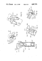
- FIG. 3 is a side elevational view of a tank valve employed in the system of FIG. 1;
- FIG. 4 is a detail cross-sectional view of the tank valve taken on line 4--4 of FIG. 3;
- FIG. 5 is a top plan view of the tank valve of FIG. 3;
- FIG. 6 is a cross-sectional view taken on line 6--6 of FIG. 5;
- FIG. 7 is a cross-sectional view taken on line 7--7 of FIG. 5;
- FIG. 8 is a schematic diagram of a second embodiment of a refueling vapor recovery system embodying the present invention.
- FIG. 9 is a detail cross-sectional view of the inlet end of the fuel tank filler pipe of the system of FIG. 8;
- FIG. 10 is a side elevational view of a portion of the filler pipe of the system of FIG. 8 taken approximately from a plane 10--10 of FIG. 9;
- FIG. 11 is a detail cross-sectional view taken on line 11--11 of FIG. 10;
- FIG. 12 is a detail cross-sectional view taken on line 12--12 of FIG. 10;
- FIG. 13 is a side elevational view, partially in section, of a tank valve employed in the system of FIG. 8;
- FIG. 14 is a top plan view of the tank valve of the system of FIG. 8.
- FIG. 15 is a cross-sectional view taken on line 15--15 of FIG. 14.
- the fuel tank 20 of a vehicle is provided, in a conventional manner, with a fill pipe 22 connected at its upper end to a fill neck assembly designated generally 24 normally closed by a cap 26.
- a tank valve designated generally 28 is sealingly mounted in the top wall of fuel tank 20 and is connected externally of the tank via a conduit 32 to a refueling vapor canister 34 and via a second conduit 36 to a running vapor canister 38.
- Running vapor canister 38 is vented to atmosphere by a vent 42 which functions as a vent to the head space of fuel tank 20 via the canister 38, conduit 36 and passage means in tank valve 28 to be described in more detail below.
- Running vapor canister 38 is provided with an outlet which is connected via conduit 44, T fitting 46, purge valve 48 and conduit 50 to the intake manifold 52 of the internal combustion engine 54 which powers the vehicle.
- purge valve 48 When engine 54 is running and purge valve 48 is open, the vacuum existing in intake manifold 52 will draw fuel vapor from running vapor canister 38 via conduits 44, 50 into the intake manifold to be mixed with the fuel mixture supplied to the manifold via the carburetor or fuel injection pump, not shown. Opening and closing of purge valve 48 is under the control of a computer 56 which is programmed to open and close purge valve 48 in response to variations in various characteristics and parameters of engine operating conditions to assure that the fuel mixture in manifold 52 will not be overly enriched by the addition of fuel vapor.
- Running vapor recovery systems employing a running vapor canister 38 and a computer controlled purge valve 48 as described above have been employed for several years to minimize the escape of fuel vapor to the atmosphere through the fuel tank vent.
- Vapor pressure in the head space of fuel tank 20 is variable and dependent primarily upon temperature and the volatility of the fuel contained in tank 20. Because consumption of fuel during normal operation of the engine does not require any substantial inflow of pressure equalizing air into the head space of the tank via the vent, the vapor flow passages of the running vapor recovery system are relatively restricted so that discharge of fuel vapor through the vent in response to short term increases of vapor pressure in the tank is minimized.
- the present invention provides a refueling vapor recovery system which acts in parallel conjunction with the present day running vapor recovery system described above.
- FIG. 1 In addition to the refueling vapor canister 34 and tank valve 28, the system of FIG. 1 includes a fill neck assembly best shown in FIG. 2.
- fill neck assembly 24 includes a main housing 56 of generally hollow tubular configuration formed from a suitable plastic or non-magnetic material.
- the lower end of housing 56 is sealingly received in the upper end of fill pipe 22 and a cup shaped insert 58 is snugly received within the upper end of housing 56 to provide an internal thread for receiving the closure cap 26 and to provide a transverse partition or bulk head 60 extending across the interior of the tubular housing 56.
- a circular opening through partition 60 mounts an annular seal 62 which defines a passage through partition 60.
- a plate like trap door seal 64 hingedly mounted as at 66 on the under side of partition 60 is spring biassed to the closed position shown in full line in FIG. 2 in which plate 60 engages the under or inner side of annular seal 62 to act as a one-way valve preventing flow of liquid or vapor upwardly from fill pipe 22 through the passage defined by the annular seal 62.
- annular seal 62 The internal diameter of annular seal 62 is such that the seal will slidably and sealingly receive the tubular fuel dispensing nozzle of a conventional service station fuel pump, such nozzles being constructed to an industry standard outer diameter.
- Suitable portions of fill neck assembly 24 which will be contacted by the fuel dispensing nozzle are provided with means, not shown, for electrically grounding the nozzle to the vehicle frame during the refueling operation.
- the trap door plate 64 Upon removal of closure cap 26 and the insertion of the fuel dispensing nozzle through seal 62, the trap door plate 64 will be hinged by the nozzle to the broken line position shown in FIG. 2 at which time a magnet 68 carried on trap door plate 64 will be in close enough proximity to a magnetically actuated reed switch 70 to close the contacts of the switch. Although the trap door seal plate 64 is opened by the insertion of the fuel dispensing nozzle, the interior of fill pipe 22 remains sealed from the atmosphere by the engagement of the annular seal 62 with the outer side of the inserted nozzle.
- tank valve 28 includes a housing 80 which, as best seen in FIG. 4, is fixedly and sealingly mounted within an opening 82 through the top wall of fuel tank 20.
- a hollow tubular float valve-rollover valve housing 84 is fixedly secured to the bottom of main housing 80 to project vertically downwardly into the interior of tank 20.
- Housing 84 is formed with various openings 86, 88 through its side wall and the interior of housing 88 constitutes an inlet from the interior of tank 20 to an inlet passage 90 (FIGS. 4 and 6) of housing 80.
- a combination float-rollover valve member 94 mounted for vertical sliding movement within housing 84 (FIG. 4) is a combination float-rollover valve member 94 guided for vertical movement within housing 84 as by inwardly projecting ribs 96. Ribs 96 are spaced circumferentially about the interior of housing 84 so that vapor can flow freely upwardly through housing 84 from openings such as 88 located at the bottom of the housing as well as through openings 86.
- a downwardly facing frusto-conical valve seat 98 is formed in the interior of housing 84 to cooperate with a hemispherical valve head portion 100 on the float-rollover valve member 94.
- Valve member 94 is normally gravitationally maintained in the position shown in FIG. 4 spaced clear of valve seat 98, however when the level of fuel in tank 20 rises to a predetermined level the float member 94 is elevated by the rising fuel to seat against valve seat 98 and block fluid communication between the interior of tank 20 and inlet passage 90 of the main valve housing 80. Valve member 94 is provided with a sealed internal buoyancy chamber 102.
- a metal ball 104 is engaged between a frusto-conical recess in the bottom of valve member 94 and a similar oppositely oriented frusto-conical surface 108 fixedly mounted at the bottom of housing 84.
- housing 84 is tilted more than approximately 20° from the vertical, ball 104 will move out of a centered relationship with the opposed frusto-conical surfaces and cam valve member 94 upwardly into seated engagement with valve seat 98.
- inlet passage 90 in housing 80 opens at its upper end into an internal chamber 110 in housing 80 which in turn opens at its left side as viewed in FIG. 6 into a main outlet passage 112 which extends outwardly through a projecting hose coupling 114 formed on housing 28.
- Communication between chamber 110 and outlet passage 112 is controlled by a valve head 116 carried on the armature 118 of solenoid 76, valve head 116 being movable from the open position shown in FIG. 6 to a closed position in seated engagement with a valve seat 120 at the entrance to passage 112.
- Armature 110 is resiliently biassed to the left as viewed in FIG.
- valve head 116 is maintained by spring 122 in seated engagement with its seat 120 at all times when solenoid 76 is not energized.
- solenoid 76 is energized by the closure of reed switch 70 as described above, armature 118 is withdrawn to the right to the position shown in FIG. 6 to place the head space in fuel tank 20 in communication with conduit 32 mounted on hose coupling 20 via inlet passage 90, chamber 110 and passage 112. As described above, this communication is established by the insertion of the fuel dispensing nozzle into fill neck assembly 24 through annular seal 62 and the consequent closure of the contacts of reed switch 70 by the displacement of the trap door in the fill neck.
- Termination of the refueling operation is made known to the system either by withdrawing the fuel dispensing nozzle from the fill neck, thus de-energizing solenoid 76 and engaging valve head 116 on seat 120 or by the filling of the tank to a level such that float valve member 94 is seated on its valve seat 98. Either of these two latter events blocks communication between the head space of fuel tank 20 and refueling vapor canister 34 via conduit 32.
- Fluid communication between the head space of tank 20 and running vapor canister 38 via conduit 36 is established through tank valve 28 via an inlet passage 122 (FIG. 4) which extends through housing 80 from an inlet 124 opening into the head space of the tank to a chamber 126 and from chamber 126 through an outlet passage 128 extending through a projecting hose coupling 130 formed on housing 80.
- running vapor canister 38 is in direct communication with the head space of fuel tank 20 at all times via conduit 36, passage 128, chamber 126, inlet passage 122 and inlet opening 124.
- a normally open rollover valve designated generally 132 is located near the lower end of inlet passage 122 to block inlet passage 122 in the event of a vehicle rollover condition.
- Valve 132 includes a rounded valve head 134 which rests upon the top of a relatively light compression spring 136.
- Spring 136 is so calibrated that it is normally unable to lift valve head 134 vertically, but is strong enough to move valve head 134 upwardly into engagement with a valve seat and passage 122 along a path inclined from the vertical by about 20° or more to close the valve in the event of a vehicle rollover.
- a combination vacuum/pressure relief valve designated generally 138 is also incorporated in tank valve 28. Details of valve 138 are best shown in FIG. 4.
- tank valve housing 80 is formed with a chamber 140 located above chamber 126.
- a passage 142 leads from chamber 140 into the main outlet passage 112 of tank valve 28, see FIG. 6, the course of this passage 142 lying generally beneath valve cover 144 as shown in the plan view of FIG. 5.
- chamber 126 is in communication at all times with running vapor canister 38 via conduit 36, while chamber 140 is in communication at all times with refueling vapor canister 34 via passage 142, passage 112 (FIG. 6) and conduit 32.
- Communication between chambers 126 and 140 is normally blocked by a main valve head 146 which is biassed downwardly by a spring 148 to close and seal the open upper end of chamber 126.
- a second valve head 150 is normally biassed upwardly against the bottom of valve head 146 by a spring 152 to close a passage 154 which extends centrally upwardly through valve head 146.
- vacuum/pressure relief valve 138 The primary purpose of vacuum/pressure relief valve 138 is to provide such relief to the head space of tank 20 during normal operation of the vehicle in the event the vent 42 of running vapor canister 38 malfunctions, as by a blockage of the vent.
- the head space of fuel tank 20 is vented to atmosphere through the running vapor canister vent 42 to provide pressure compensation for the withdrawal of fuel from the tank by operation of the vehicle engine 54.
- vapor is discharged from the head space of tank 20 into running vapor canister 38.
- vent 42 may result in either an undesirable increase or decrease of pressure in the head space of tank 20.
- Refueling vapor canister 34 is provided with a vent 156 (FIG. 1) which may incorporate a one-way check valve oriented to block discharge of vapor from canister 34 into the atmosphere while accommodating flow of air into canister 34 if the pressure within the canister falls below atmospheric pressure.
- the head space of tank 20 may thus be vented via the refueling vapor canister.
- the system of FIG. 1 includes two emergency devices operable in the event the fuel dispensing nozzle is not shut off when the tank is filled.
- Present day fuel nozzles are almost universally equipped with an automatic shutoff device which will shut off the nozzle in response to the backing up of fuel in the filler pipe.
- the system will first produce an audible warning signal from a whistle device designated generally 160 incorporated in tank valve 28. If this signal is ignored, continued flow of fuel into the tank will open an emergency liquid relief valve designated generally 162 (FIG. 2) to allow liquid fuel in fill pipe 22 to bypass nozzle seal 62 and spill from the fill pipe.
- Whistle device 160 is actuated in response to an increase in pressure in the head space of fuel tank 20 above a preselected pressure.
- housing 80 is formed with an inlet 164 opening directly into the head space of the fuel tank. Communication between inlet 164 and a chamber 166 in housing 80 is normally blocked by a valve head 168 held against a valve seat 170 by a compression spring 172. An outlet 174 of chamber 166 communicates with a whistle located within a housing 176, the whistle being vented to atmosphere.
- the emergency liquid relief valve 162 is best shown in FIG. 2.
- An opening 178 through the wall of fill neck 24 is normally closed by a valve head 180 biassed to the closed position by a spring 182, the valve head and spring being located within a housing 184 at one side of fill neck 24.
- Housing 184 also encloses a second opening 186 through the wall of fill neck 24 located at the inlet side of annular seal 62.
- valve head 180 will be forced clear of opening 178 to permit liquid to flow through opening 178, the interior of housing 184 and into the open inlet end of fill neck 24 to spill from the fill neck.
- whistle device 160 While operation of whistle device 160 will vent fuel vapor from tank 20 directly into the atmosphere and operation of the emergency liquid relief valve 162 will spill raw fuel from the vehicle, these devices are operable only in an emergency situation which might otherwise lead to rupture of fuel tank 20 or associated components from excessive internal pressure.
- Actuation of the fuel dispensing nozzle to dispense fuel into tank 20 will cause a consequent displacement of fuel vapor from the head space of tank 20 past the open float valve and open solenoid valve and thence through conduit 32 to the refueling vapor canister.
- Fuel vapor from the head space of tank 20 can also at this time flow to the running vapor canister 38 via the normally open passage 122 (FIG. 4), chamber 126, outlet passage 128 and conduit 36.
- this latter flow path from tank 20 to the running vapor canister 38 is relatively restricted as compared to the flow path from tank 20 to refueling vapor canister 34 and by far the major portion of fuel vapor displaced from tank 20 by the incoming fuel will flow into refueling vapor canister 34.
- the head space in tank 20 is vented via the vent 42 in running vapor canister 38 to provide pressure compensation for the consumption of fuel from tank 20 by the engine.
- purge valve 48 is opened and closed under the control of computer 56 so that fuel vapor can be withdrawn at a controlled rate from running vapor canister 38 and refueling vapor canister 34 for combustion in engine 58.
- FIG. 8 a modified form of refueling vapor recovery system is shown.
- the system of FIG. 8 differs from that of FIG. 1 primarily in the employment of a mechanically actuated valve, as opposed to the solenoid actuated valve of the FIG. 1 system, to establish communication between the head space of the fuel tank and the refueling vapor canister during the refueling operation.
- various parts of the system of FIG. 8 are similar in construction and function to corresponding parts of the system of FIG. 1 described above.
- a vehicle fuel tank 200 is connected in a conventional manner to a fill pipe connected at its upper end to a fill neck assembly designated generally 204 which is normally closed by a conventional closure cap 206.
- a tank valve designated generally 208 is sealingly mounted in and projects through the upper wall of tank 200 to control, in a manner to be described in greater detail below, fluid communication between the head space of tank 200, a running vapor canister 210 and a refueling vapor canister 212.
- Outlets 214 and 216, respectively, of running vapor canister 210 and refueling vapor canister 212 are commonly connected to a computer controlled purge valve 218 whose outlet in turn is connected to the intake manifold of the vehicle engine designated generally 220.
- the computer controlled purge valve functions in the same manner as purge valve 48 of the FIG. 1 embodiment to enable the vehicle engine, when running, to withdraw fuel vapor at a controlled rate from canisters 210 and 212 for combustion in engine 220.
- fill neck 204 includes a generally tubular housing 222 having a cup-shaped insert 224 seated in its upper end to provide an internal thread for cap 206.
- the bottom of insert 224 is formed with a circular opening 226 within which is mounted an annular nozzle seal 228 normally closed at its lower or inner end by a spring biassed trap door seal designated generally 230.
- the insert 224, seal 228 and trap door seal 230 are constructionally and functionally equivalent to the corresponding elements of fill neck 24 described above.
- An emergency liquid relief valve designated generally 232 of the same construction and function as the emergency relief valve 162 of fill neck 24 of the FIG. 1 embodiment is mounted on fill neck 204.
- Suitable portions of fill neck assembly 24 which will be contacted by the fuel dispensing nozzle are provided with means, not shown, for electrically grounding the nozzle to the vehicle frame during the refueling operation.
- valve housing 236 is formed with an inner chamber 238 which opens at its right-hand end as viewed in FIG. 9 into a chamber 240 of somewhat larger dimensions which defines an annular shoulder 242 around the open end of chamber 238.
- a valve head 244 is normally biassed against shoulder 242 by a spring 246 to block communication between chambers 238 and 240.
- valve stem 248 fixed to valve head 244 slidably projects through a bore 250 in housing 236 and into the interior of main housing 222.
- valve stem 248 Upon hinging movement of the trap door valve 230 to its open position, indicated in broken line in FIG. 9, by the insertion of a fuel dispensing nozzle N through annular seal 228, valve stem 248 will be driven to the right as viewed in FIG. 9 by the trap door to lift valve head 244 clear of shoulder 242 to place chambers 238 and 240 in communication with each other.
- An inlet 252 to chamber 238 communicates with a hose coupling 254 which is in turn (FIG. 8) connected by a hose or other suitable conduit schematically indicated at 256 to a hose coupling 258 on tank valve 208.
- Fuel vapor from the head space of tank 200 can, under conditions to be described below, flow from tank 200 through conduit 256 into chamber 238 and, when valve head 244 is unseated, pass through chamber 240 to an outlet 260 (FIG. 11) of chamber 240 and thence through a conduit 262 connected to a coupling 264 communicating with outlet 260 to refueling vapor canister 212.
- Vapor can flow from tank 200 to refueling canister 212 through the foregoing path only when refueling valve 234 is held open by the insertion of a refueling nozzle through annular seal 228.
- a fuel vapor vent for venting fuel vapor from that portion of fill neck 204 at the tank side of seal 228 is also provided in housing 236.
- the vapor vent valve is best shown in FIG. 12 and includes a passage having successive sections 266a, 266b, 266c, which extend from the interior of housing 222 through housing 236 into chamber 240. Fluid communication between sections 266a and 266b of this passage is controlled by a cage 268 which retains a relatively lightweight ball 272 which can seat in either of two openings 273, 274 at opposite ends of the cage to block communication between passage sections 266a and 266b when so seated.
- the weight of the ball is such that it may be easily lifted from the lower seat 273 if the vapor pressure within fill neck housing 222 exceeds the pressure in chamber 240 to vent vapor from the fill neck into chamber 266b and thence to the refueling vapor canister.
- Tank valve 208 of the system in FIG. 8 includes many of the same components utilized in tank valve 28 of the system of FIG. 1. Components of tank valve 208 which are common with components of tank valve 28 are identified by primed reference numerals corresponding to the reference numerals employed for tank valve 28.
- tank valve 208 includes a float-rollover valve assembly of the same construction as that employed in tank valve 28, including a float-rollover valve member 94' guided for movement within the float-rollover housing 84' as by ribs, 96'.
- a downwardly facing frusto-conical valve seat within housing 84' is located to be engaged and sealed by the hemispherical valve head portion 100' of the float-rollover member 94' when this member is elevated either by a rise of fuel level within tank 200 or cammed upwardly by ball 104' in the event of a vehicle rollover.
- tank valve 28 included a solenoid actuated valve controlling communication between its inlet 90 and outlet passage 112.
- the function of the solenoid valve of the FIG. 1 embodiment is performed by the refuel valve 234 located at the vehicle fill neck.
- the inlet 90' is in direct communication at all times with the outlet passage 212'.
- a combination vacuum/pressure relief valve 142' incorporating a rollover valve 132' in its inlet from the tank are also employed in tank valve 208.
- the valves 142' and 132' of tank valve 208 are identical in structure to the respective valves 142 and 132 of the FIG. 1 embodiment.
- vacuum/pressure relief valve 142' communicates with the running vapor canister 210 via a hose coupling 130' and conduit 36'. Communication between valve 142' and the refueling vapor canister 212 of the FIG. 8 embodiment is via a hose coupling 276 and conduit 278.
- refueling vapor canister 210 of the FIG. 8 embodiment is provided with a vent 42' and refueling vapor canister 212 may also be provided with a vent 156.
- valve which places the refueling vapor canister in communication with the head space of the fuel tank only during a refueling operation.
- this valve is constituted by the solenoid valve on tank valve 28 which includes valve head 116 and seat 120.
- the refuel valve 234 is located on the fill neck. Space limitations in the particular vehicle in which the system is employed may make one of these systems preferable to the other.
- the system of FIG. 8 provides a fill neck vent valve operable to vent fuel vapor from the fill neck to the refueling vapor canister at all times during the refueling event when the vapor pressure in the fill neck is sufficient to lift ball 272 (FIG. 12) off its seat.
- a fill neck vent valve operable to vent fuel vapor from the fill neck to the refueling vapor canister at all times during the refueling event when the vapor pressure in the fill neck is sufficient to lift ball 272 (FIG. 12) off its seat.
- Such a valve might be incorporated in the system of FIG. 1 if desired.
Landscapes
- Engineering & Computer Science (AREA)
- Chemical & Material Sciences (AREA)
- Combustion & Propulsion (AREA)
- Mechanical Engineering (AREA)
- Life Sciences & Earth Sciences (AREA)
- Sustainable Development (AREA)
- Sustainable Energy (AREA)
- Transportation (AREA)
- General Engineering & Computer Science (AREA)
- Cooling, Air Intake And Gas Exhaust, And Fuel Tank Arrangements In Propulsion Units (AREA)
Abstract
Description
Claims (27)
Priority Applications (1)
| Application Number | Priority Date | Filing Date | Title |
|---|---|---|---|
| US07/101,069 US4887578A (en) | 1987-09-25 | 1987-09-25 | On board refueling vapor recovery system |
Applications Claiming Priority (1)
| Application Number | Priority Date | Filing Date | Title |
|---|---|---|---|
| US07/101,069 US4887578A (en) | 1987-09-25 | 1987-09-25 | On board refueling vapor recovery system |
Publications (1)
| Publication Number | Publication Date |
|---|---|
| US4887578A true US4887578A (en) | 1989-12-19 |
Family
ID=22282928
Family Applications (1)
| Application Number | Title | Priority Date | Filing Date |
|---|---|---|---|
| US07/101,069 Expired - Lifetime US4887578A (en) | 1987-09-25 | 1987-09-25 | On board refueling vapor recovery system |
Country Status (1)
| Country | Link |
|---|---|
| US (1) | US4887578A (en) |
Cited By (90)
| Publication number | Priority date | Publication date | Assignee | Title |
|---|---|---|---|---|
| US5027780A (en) * | 1988-02-18 | 1991-07-02 | Toyota Jidosha Kabushiki Kaisha | Air-fuel control device for an internal combustion engine |
| US5054455A (en) * | 1989-12-18 | 1991-10-08 | Siemens-Bendix Automotive Electronics Limited | Regulated flow canister purge system |
| US5067468A (en) * | 1989-04-03 | 1991-11-26 | Toyota Jidosha Kabushiki Kaisha | Apparatus for preventing discharge of fuel vapor |
| US5085197A (en) * | 1989-07-31 | 1992-02-04 | Siemens Aktiengesellschaft | Arrangement for the detection of deficiencies in a tank ventilation system |
| US5103877A (en) * | 1991-04-15 | 1992-04-14 | General Motors Corporation | Vapor-liquid separator for evaporative emissions control system |
| US5110010A (en) * | 1990-09-21 | 1992-05-05 | Gilbarco, Inc. | Automatic fuel dispenser actuator |
| US5111795A (en) * | 1991-08-09 | 1992-05-12 | Ford Motor Company | Fluidic controller for automotive fuel tank vapor collection system |
| US5143041A (en) * | 1989-06-28 | 1992-09-01 | Robert Bosch Gmbh | Venting device for a fuel tank of an internal combustion engine |
| US5148793A (en) * | 1991-05-20 | 1992-09-22 | General Motors Corporation | Compartmental evaporative canister and pressure control valve assembly |
| WO1992018764A1 (en) * | 1991-04-09 | 1992-10-29 | Robert Bosch Gmbh | Process and device for testing a fuel tank ventilation system |
| US5165379A (en) * | 1991-08-09 | 1992-11-24 | Ford Motor Company | Automotive fuel tank vapor control system |
| US5170765A (en) * | 1991-02-01 | 1992-12-15 | Honda Giken Kogyo Kabushiki Kaisha | Canister for storing fuel |
| US5194075A (en) * | 1991-04-01 | 1993-03-16 | Toyota Jidosha Kabushiki Kaisha | Evaporative fuel recovery apparatus |
| US5195498A (en) * | 1991-03-19 | 1993-03-23 | Robert Bosch Gmbh | Tank-venting apparatus as well as a method and arrangement for checking the tightness thereof |
| US5235955A (en) * | 1991-06-21 | 1993-08-17 | Kyosan Denki Kabushiki Kaisha | Fuel evaporative emission control system |
| US5259412A (en) * | 1992-08-14 | 1993-11-09 | Tillotson, Ltd. | Fuel tank vapor recovery control |
| US5261379A (en) * | 1991-10-07 | 1993-11-16 | Ford Motor Company | Evaporative purge monitoring strategy and system |
| US5277168A (en) * | 1992-03-12 | 1994-01-11 | Aisan Kogyo Kabushiki Kaisha | Fuel outflow preventing apparatus of fuel tank for vehicle |
| US5280775A (en) * | 1991-04-27 | 1994-01-25 | Toyo Denso Kabushiki Kaisha | Fuel vapor control valve device |
| US5305807A (en) * | 1993-04-22 | 1994-04-26 | Healy Systems, Inc. | Auxiliary vapor recovery device for fuel dispensing system |
| US5318069A (en) * | 1992-01-17 | 1994-06-07 | Stant Manufacturing Inc. | Tank venting and vapor recovery system |
| EP0648637A1 (en) * | 1993-09-15 | 1995-04-19 | General Motors Corporation | Vapour recovery system |
| US5456237A (en) * | 1993-10-04 | 1995-10-10 | Honda Giken Kogyo Kabushiki Kaisha | Evaporative fuel processing device |
| US5477836A (en) * | 1994-02-02 | 1995-12-26 | Toyota Jidosha Kabushiki Kaisha | Fuel vapor emission control system for an engine |
| US5524662A (en) * | 1990-01-25 | 1996-06-11 | G.T. Products, Inc. | Fuel tank vent system and diaphragm valve for such system |
| US5592922A (en) * | 1994-03-16 | 1997-01-14 | Robert Bosch Gmbh | Venting apparatus for a fuel system of an internal combustion engine |
| US5603349A (en) * | 1992-01-17 | 1997-02-18 | Stant Manufacturing Inc. | Tank venting system |
| US5632252A (en) * | 1995-02-13 | 1997-05-27 | Toyota Jidosha Kabushiki Kaisha | Apparatus for controlling fuel evaporated from internal combustion engine |
| WO1997021561A1 (en) * | 1995-12-11 | 1997-06-19 | Alfmeier Corporation | Vapor recovery fuel tank system |
| EP0781677A1 (en) * | 1995-12-27 | 1997-07-02 | Hyundai Motor Company | Vent valve for vehicle fuel tank |
| US5676116A (en) * | 1996-07-09 | 1997-10-14 | Kia Motors Corporation | Vapor pressure control system |
| US5782275A (en) * | 1996-05-17 | 1998-07-21 | Gilbarco Inc. | Onboard vapor recovery detection |
| US5809976A (en) * | 1995-11-29 | 1998-09-22 | Siemens Canada Limited | Vent control valving for fuel vapor recovery system |
| US5850819A (en) * | 1994-12-09 | 1998-12-22 | Mitsubishi Jidosha Kogyo Kabushiki Kaisha | Fuel evaporative emission treatment system |
| US5868179A (en) * | 1997-03-04 | 1999-02-09 | Gilbarco Inc. | Precision fuel dispenser |
| US5890520A (en) * | 1997-09-26 | 1999-04-06 | Gilbarco Inc. | Transponder distinction in a fueling environment |
| US5956259A (en) * | 1995-12-08 | 1999-09-21 | Gilbarco Inc. | Intelligent fueling |
| US6012434A (en) * | 1998-07-20 | 2000-01-11 | Outboard Marine Corporation | Fuel system vapor separator for an internal combustion engine |
| US6026866A (en) * | 1997-08-11 | 2000-02-22 | Gilbarco Inc. | Onboard vapor recovery detection nozzle |
| US6070156A (en) * | 1997-09-26 | 2000-05-30 | Gilbarco Inc. | Providing transaction estimates in a fueling and retail system |
| US6073840A (en) * | 1997-09-26 | 2000-06-13 | Gilbarco Inc. | Fuel dispensing and retail system providing for transponder prepayment |
| US6078888A (en) * | 1997-07-16 | 2000-06-20 | Gilbarco Inc. | Cryptography security for remote dispenser transactions |
| US6089284A (en) * | 1998-09-24 | 2000-07-18 | Marconi Commerce Systems Inc. | Preconditioning a fuel dispensing system using a transponder |
| US6095204A (en) * | 1996-03-20 | 2000-08-01 | Healy Systems, Inc. | Vapor recovery system accommodating ORVR vehicles |
| US6098879A (en) * | 1997-09-26 | 2000-08-08 | Gilbarco, Inc. | Fuel dispensing system providing customer preferences |
| US6102085A (en) * | 1998-11-09 | 2000-08-15 | Marconi Commerce Systems, Inc. | Hydrocarbon vapor sensing |
| US6169938B1 (en) | 1995-12-08 | 2001-01-02 | Marconi Commerce Systems Inc. | Transponder communication of ORVR presence |
| US6167920B1 (en) * | 1999-05-28 | 2001-01-02 | Borgwarner Inc. | Electromechanical refueling control system |
| US6253802B1 (en) * | 1999-05-28 | 2001-07-03 | Borgwarner Inc. | Electromechanically controlled refueling valve |
| US6263319B1 (en) | 1997-09-26 | 2001-07-17 | Masconi Commerce Systems Inc. | Fuel dispensing and retail system for providing a shadow ledger |
| US20010020198A1 (en) * | 1997-09-26 | 2001-09-06 | Wilson Amy Hetz | Fuel dispensing system for cash customers |
| US6313737B1 (en) | 1998-06-23 | 2001-11-06 | Marconi Commerce Systems Inc. | Centralized transponder arbitration |
| US6363299B1 (en) | 1998-08-25 | 2002-03-26 | Marconi Commerce Systems Inc. | Dispenser system for preventing unauthorized fueling |
| US6470233B1 (en) | 1997-09-26 | 2002-10-22 | Gilbarco Inc. | Fuel dispensing and retail system for preventing use of stolen transponders |
| US6574603B1 (en) | 1997-09-26 | 2003-06-03 | Gilbarco Inc. | In-vehicle ordering |
| FR2844486A1 (en) * | 2002-09-13 | 2004-03-19 | Inergy Automotive Systems Res | Sealing safety device for filling fuel tank comprises annular joint surrounding filling gun and elastomer valve comprising annular lip, which only opens to create passage to atmosphere in event of overpressure in tank |
| US6708713B1 (en) | 1999-04-16 | 2004-03-23 | Tesma International Inc. | Fill limit control valve assembly having a liquid fuel trap |
| EP1426225A1 (en) * | 2002-12-03 | 2004-06-09 | Eaton Corporation | Electrically controlled refueling vapor vent shutoff |
| US6882900B1 (en) | 1997-09-26 | 2005-04-19 | Gilbarco Inc. | Fuel dispensing and retail system for providing customer selected guidelines and limitations |
| US20050279406A1 (en) * | 2004-06-22 | 2005-12-22 | Atwood Jeffrey M | Vehicle fuel system |
| US20080041348A1 (en) * | 2006-04-12 | 2008-02-21 | Grant Jeffrey P | Fuel tank with integrated evaporative emissions system |
| US7431021B1 (en) | 2007-09-19 | 2008-10-07 | Federal - Mogul World Wide, Inc. | Fuel vapor separator |
| US20090063027A1 (en) * | 2005-08-23 | 2009-03-05 | Inergy Automotive Systems Research | Fuel or Additive Pump Controller |
| US20090056680A1 (en) * | 2005-04-01 | 2009-03-05 | Inergy Automotive Sys. Research (Societe Anonyme ) | Electronic venting and mechanical roll over valve |
| US20090078239A1 (en) * | 2006-01-31 | 2009-03-26 | Inergy Automotive Systems Research (S.A.) | Method For Recovering Vapor During An Onboard Refueling Operation |
| US20090099795A1 (en) * | 2006-02-07 | 2009-04-16 | Inergy Automotive Systems Research (S.A.) | Leak detection method and associated valve and fuel system |
| US20090139783A1 (en) * | 2007-12-04 | 2009-06-04 | Dr. Ing. H.C.F. Porsche Aktiengesellschaft | Hybrid Vehicle |
| US20090139989A1 (en) * | 2007-11-30 | 2009-06-04 | Wolfgang Mai | Tank venting device for a motor vehicle |
| US20090150041A1 (en) * | 2004-10-28 | 2009-06-11 | Inergy Auto. Systems Research (Societe Anonyme) | Refuelling system and method |
| US20090187327A1 (en) * | 2005-08-22 | 2009-07-23 | Inergy Automotive Systems Research | Liquid Pump Control System |
| WO2009111942A1 (en) * | 2008-03-14 | 2009-09-17 | 无锡开普动力有限公司 | Canister-connecting structure for portable electric generating set |
| US8167003B1 (en) | 2008-08-19 | 2012-05-01 | Delaware Capital Formation, Inc. | ORVR compatible refueling system |
| US20120138169A1 (en) * | 2010-12-06 | 2012-06-07 | Hyundai Motor Company | Fuel tank vaporization gas purge system |
| DE102011001310A1 (en) * | 2011-03-16 | 2012-09-20 | Dr. Ing. H.C. F. Porsche Aktiengesellschaft | Tank system for a motor vehicle |
| US20130174800A1 (en) * | 2005-03-09 | 2013-07-11 | Rem Technology Inc. | Apparatus for providing diluted fugitive gases as a fuel to an engine |
| US20140007963A1 (en) * | 2011-03-23 | 2014-01-09 | Audi Ag | Tank ventilation device for a motor vehicle |
| US20140144411A1 (en) * | 2012-11-28 | 2014-05-29 | Mitsubishi Jidosha Kogyo Kabushiki Kaisha | Fuel evaporation gas discharge suppressing device of internal combustion engine |
| US20160123280A1 (en) * | 2014-10-29 | 2016-05-05 | Aisan Kogyo Kabushiki Kaisha | Vaporized fuel processing apparatus |
| US20160215714A1 (en) * | 2015-01-27 | 2016-07-28 | Ford Global Technologies, Llc | Systems and methods for inferring fuel vapor canister loading rate |
| US20160215715A1 (en) * | 2015-01-27 | 2016-07-28 | Ford Global Technologies, Llc | Systems and methods for inferring fuel vapor canister loading rate |
| US9404446B2 (en) | 2013-12-04 | 2016-08-02 | Nissan North America, Inc. | Vehicle fuel vapor recovery system |
| US9457649B2 (en) | 2013-12-04 | 2016-10-04 | Nissan North America, Inc. | Vehicle fuel vapor recovery system |
| US20170129329A1 (en) * | 2015-11-10 | 2017-05-11 | Hamanakodenso Co., Ltd. | Fuel Vapor Gas Purge System |
| US20170137022A1 (en) * | 2015-11-12 | 2017-05-18 | Ford Global Technologies, Llc | Systems and methods for detection and mitigation of liquid fuel carryover in an evaporative emissions system |
| US9745907B2 (en) * | 2015-01-27 | 2017-08-29 | Ford Global Technologies, Llc | Systems and methods for inferring fuel vapor canister loading rate |
| US10364762B2 (en) | 2015-01-27 | 2019-07-30 | Ford Global Technologies, Llc | Systems and methods for inferring fuel vapor canister loading rate |
| US11186166B2 (en) * | 2018-09-27 | 2021-11-30 | Kyosan Denki Co., Ltd. | Fuel tank ventilation valve |
| US11236708B1 (en) * | 2020-08-28 | 2022-02-01 | Hyundai Motor Company | Fuel odor control system for vehicle |
| US11518237B2 (en) | 2020-01-27 | 2022-12-06 | Cnh Industrial America Llc | Fluid tank system |
| US11584221B2 (en) * | 2018-06-11 | 2023-02-21 | Eaton Intelligent Power Limited | Evaporative emissions fuel tank venting system positioned in vapor line |
Citations (7)
| Publication number | Priority date | Publication date | Assignee | Title |
|---|---|---|---|---|
| US3957025A (en) * | 1974-11-04 | 1976-05-18 | Rohr Industries, Inc. | Method and apparatus for controlling displaced vapor emissions in motor vehicles |
| US4000727A (en) * | 1973-09-14 | 1977-01-04 | Brooks Walker | Vehicle retrofit gasoline evaporation control device |
| US4701198A (en) * | 1984-03-24 | 1987-10-20 | Toyota Jidosha Kabushiki Kaisha | Fuel tank for use in a motor vehicle |
| US4706708A (en) * | 1986-06-23 | 1987-11-17 | General Motors Corporation | Fuel tank venting |
| US4724861A (en) * | 1986-08-18 | 1988-02-16 | General Motors Corporation | Fuel tank venting |
| US4760863A (en) * | 1986-06-16 | 1988-08-02 | Broer Peter C | Pressure vacuum valve, more particularly to the storage tanks for volatile liquids |
| US4768566A (en) * | 1986-02-21 | 1988-09-06 | Toyota Jidosha Kabushiki Kaisha | Fuel tank having an inlet pipe with a guide and venturi restriction |
-
1987
- 1987-09-25 US US07/101,069 patent/US4887578A/en not_active Expired - Lifetime
Patent Citations (7)
| Publication number | Priority date | Publication date | Assignee | Title |
|---|---|---|---|---|
| US4000727A (en) * | 1973-09-14 | 1977-01-04 | Brooks Walker | Vehicle retrofit gasoline evaporation control device |
| US3957025A (en) * | 1974-11-04 | 1976-05-18 | Rohr Industries, Inc. | Method and apparatus for controlling displaced vapor emissions in motor vehicles |
| US4701198A (en) * | 1984-03-24 | 1987-10-20 | Toyota Jidosha Kabushiki Kaisha | Fuel tank for use in a motor vehicle |
| US4768566A (en) * | 1986-02-21 | 1988-09-06 | Toyota Jidosha Kabushiki Kaisha | Fuel tank having an inlet pipe with a guide and venturi restriction |
| US4760863A (en) * | 1986-06-16 | 1988-08-02 | Broer Peter C | Pressure vacuum valve, more particularly to the storage tanks for volatile liquids |
| US4706708A (en) * | 1986-06-23 | 1987-11-17 | General Motors Corporation | Fuel tank venting |
| US4724861A (en) * | 1986-08-18 | 1988-02-16 | General Motors Corporation | Fuel tank venting |
Cited By (138)
| Publication number | Priority date | Publication date | Assignee | Title |
|---|---|---|---|---|
| US5027780A (en) * | 1988-02-18 | 1991-07-02 | Toyota Jidosha Kabushiki Kaisha | Air-fuel control device for an internal combustion engine |
| US5067468A (en) * | 1989-04-03 | 1991-11-26 | Toyota Jidosha Kabushiki Kaisha | Apparatus for preventing discharge of fuel vapor |
| US5143041A (en) * | 1989-06-28 | 1992-09-01 | Robert Bosch Gmbh | Venting device for a fuel tank of an internal combustion engine |
| US5085197A (en) * | 1989-07-31 | 1992-02-04 | Siemens Aktiengesellschaft | Arrangement for the detection of deficiencies in a tank ventilation system |
| US5054455A (en) * | 1989-12-18 | 1991-10-08 | Siemens-Bendix Automotive Electronics Limited | Regulated flow canister purge system |
| US5524662A (en) * | 1990-01-25 | 1996-06-11 | G.T. Products, Inc. | Fuel tank vent system and diaphragm valve for such system |
| US5110010A (en) * | 1990-09-21 | 1992-05-05 | Gilbarco, Inc. | Automatic fuel dispenser actuator |
| US5170765A (en) * | 1991-02-01 | 1992-12-15 | Honda Giken Kogyo Kabushiki Kaisha | Canister for storing fuel |
| US5195498A (en) * | 1991-03-19 | 1993-03-23 | Robert Bosch Gmbh | Tank-venting apparatus as well as a method and arrangement for checking the tightness thereof |
| US5194075A (en) * | 1991-04-01 | 1993-03-16 | Toyota Jidosha Kabushiki Kaisha | Evaporative fuel recovery apparatus |
| US5505182A (en) * | 1991-04-09 | 1996-04-09 | Robert Bosch Gmbh | Method and arrangement for checking a tank-venting system |
| WO1992018764A1 (en) * | 1991-04-09 | 1992-10-29 | Robert Bosch Gmbh | Process and device for testing a fuel tank ventilation system |
| US5103877A (en) * | 1991-04-15 | 1992-04-14 | General Motors Corporation | Vapor-liquid separator for evaporative emissions control system |
| US5280775A (en) * | 1991-04-27 | 1994-01-25 | Toyo Denso Kabushiki Kaisha | Fuel vapor control valve device |
| US5148793A (en) * | 1991-05-20 | 1992-09-22 | General Motors Corporation | Compartmental evaporative canister and pressure control valve assembly |
| US5235955A (en) * | 1991-06-21 | 1993-08-17 | Kyosan Denki Kabushiki Kaisha | Fuel evaporative emission control system |
| US5165379A (en) * | 1991-08-09 | 1992-11-24 | Ford Motor Company | Automotive fuel tank vapor control system |
| US5111795A (en) * | 1991-08-09 | 1992-05-12 | Ford Motor Company | Fluidic controller for automotive fuel tank vapor collection system |
| US5261379A (en) * | 1991-10-07 | 1993-11-16 | Ford Motor Company | Evaporative purge monitoring strategy and system |
| US5603349A (en) * | 1992-01-17 | 1997-02-18 | Stant Manufacturing Inc. | Tank venting system |
| US5318069A (en) * | 1992-01-17 | 1994-06-07 | Stant Manufacturing Inc. | Tank venting and vapor recovery system |
| US5388611A (en) * | 1992-01-17 | 1995-02-14 | Stant Manufacturing Inc. | Tank venting and vapor recovery system |
| US5277168A (en) * | 1992-03-12 | 1994-01-11 | Aisan Kogyo Kabushiki Kaisha | Fuel outflow preventing apparatus of fuel tank for vehicle |
| US5259412A (en) * | 1992-08-14 | 1993-11-09 | Tillotson, Ltd. | Fuel tank vapor recovery control |
| US5305807A (en) * | 1993-04-22 | 1994-04-26 | Healy Systems, Inc. | Auxiliary vapor recovery device for fuel dispensing system |
| EP0648637A1 (en) * | 1993-09-15 | 1995-04-19 | General Motors Corporation | Vapour recovery system |
| US5462100A (en) * | 1993-09-15 | 1995-10-31 | General Motors Corporation | Fuel fill vapor recovery system with differential pressure control valve |
| US5456237A (en) * | 1993-10-04 | 1995-10-10 | Honda Giken Kogyo Kabushiki Kaisha | Evaporative fuel processing device |
| US5477836A (en) * | 1994-02-02 | 1995-12-26 | Toyota Jidosha Kabushiki Kaisha | Fuel vapor emission control system for an engine |
| US5592922A (en) * | 1994-03-16 | 1997-01-14 | Robert Bosch Gmbh | Venting apparatus for a fuel system of an internal combustion engine |
| US5850819A (en) * | 1994-12-09 | 1998-12-22 | Mitsubishi Jidosha Kogyo Kabushiki Kaisha | Fuel evaporative emission treatment system |
| US5632252A (en) * | 1995-02-13 | 1997-05-27 | Toyota Jidosha Kabushiki Kaisha | Apparatus for controlling fuel evaporated from internal combustion engine |
| US5809976A (en) * | 1995-11-29 | 1998-09-22 | Siemens Canada Limited | Vent control valving for fuel vapor recovery system |
| US5956259A (en) * | 1995-12-08 | 1999-09-21 | Gilbarco Inc. | Intelligent fueling |
| US6169938B1 (en) | 1995-12-08 | 2001-01-02 | Marconi Commerce Systems Inc. | Transponder communication of ORVR presence |
| US5782258A (en) * | 1995-12-11 | 1998-07-21 | Alfmeier Corporation | Vapor recovery fuel tank system |
| WO1997021561A1 (en) * | 1995-12-11 | 1997-06-19 | Alfmeier Corporation | Vapor recovery fuel tank system |
| CN1071647C (en) * | 1995-12-27 | 2001-09-26 | 现代汽车株式会社 | Vent valve for vehicle fuel tank |
| EP0781677A1 (en) * | 1995-12-27 | 1997-07-02 | Hyundai Motor Company | Vent valve for vehicle fuel tank |
| US6095204A (en) * | 1996-03-20 | 2000-08-01 | Healy Systems, Inc. | Vapor recovery system accommodating ORVR vehicles |
| US5992395A (en) * | 1996-05-17 | 1999-11-30 | Gilbarco Inc | Onboard vapor recovery detection using pressure sensing means |
| US5782275A (en) * | 1996-05-17 | 1998-07-21 | Gilbarco Inc. | Onboard vapor recovery detection |
| US5676116A (en) * | 1996-07-09 | 1997-10-14 | Kia Motors Corporation | Vapor pressure control system |
| US5868179A (en) * | 1997-03-04 | 1999-02-09 | Gilbarco Inc. | Precision fuel dispenser |
| US5971042A (en) * | 1997-03-04 | 1999-10-26 | Gilbarco Inc. | Precision fuel dispenser |
| US6078888A (en) * | 1997-07-16 | 2000-06-20 | Gilbarco Inc. | Cryptography security for remote dispenser transactions |
| US6185307B1 (en) | 1997-07-16 | 2001-02-06 | Gilbarco Inc. | Cryptography security for remote dispenser transactions |
| US6026866A (en) * | 1997-08-11 | 2000-02-22 | Gilbarco Inc. | Onboard vapor recovery detection nozzle |
| US6098879A (en) * | 1997-09-26 | 2000-08-08 | Gilbarco, Inc. | Fuel dispensing system providing customer preferences |
| US5890520A (en) * | 1997-09-26 | 1999-04-06 | Gilbarco Inc. | Transponder distinction in a fueling environment |
| US6073840A (en) * | 1997-09-26 | 2000-06-13 | Gilbarco Inc. | Fuel dispensing and retail system providing for transponder prepayment |
| US7020541B2 (en) | 1997-09-26 | 2006-03-28 | Gilbarco Inc. | Fuel dispensing system for cash customers |
| US6813609B2 (en) | 1997-09-26 | 2004-11-02 | Gilbarco Inc. | Loyalty rewards for cash customers at a fuel dispensing system |
| US6070156A (en) * | 1997-09-26 | 2000-05-30 | Gilbarco Inc. | Providing transaction estimates in a fueling and retail system |
| US7289877B2 (en) | 1997-09-26 | 2007-10-30 | Gilbarco Inc. | Fuel dispensing system for cash customers |
| US6026868A (en) * | 1997-09-26 | 2000-02-22 | Gilbarco Inc. | Transponder distinction in a fueling environment |
| US7027890B2 (en) | 1997-09-26 | 2006-04-11 | Gilbarco Inc. | Fuel dispensing system for cash customers |
| US6263319B1 (en) | 1997-09-26 | 2001-07-17 | Masconi Commerce Systems Inc. | Fuel dispensing and retail system for providing a shadow ledger |
| US20010020198A1 (en) * | 1997-09-26 | 2001-09-06 | Wilson Amy Hetz | Fuel dispensing system for cash customers |
| US20030200008A1 (en) * | 1997-09-26 | 2003-10-23 | Wilson Amy Hetz | Loyalty rewards for cash customers at a fuel dispensing system. |
| US6470233B1 (en) | 1997-09-26 | 2002-10-22 | Gilbarco Inc. | Fuel dispensing and retail system for preventing use of stolen transponders |
| US20020014952A1 (en) * | 1997-09-26 | 2002-02-07 | Terranova Steven N. | Fuel dispensing and retail system for providing customer selected guidelines and limitations |
| US6574603B1 (en) | 1997-09-26 | 2003-06-03 | Gilbarco Inc. | In-vehicle ordering |
| US6882900B1 (en) | 1997-09-26 | 2005-04-19 | Gilbarco Inc. | Fuel dispensing and retail system for providing customer selected guidelines and limitations |
| US20020062174A1 (en) * | 1997-09-26 | 2002-05-23 | Wilson Amy Hetz | Fuel dispensing system for cash customers |
| US6422464B1 (en) | 1997-09-26 | 2002-07-23 | Gilbarco Inc. | Fuel dispensing system providing customer preferences |
| US20020107608A1 (en) * | 1997-09-26 | 2002-08-08 | Wilson Amy Hetz | Fuel dispensing system for cash customers |
| US6810304B1 (en) | 1997-09-26 | 2004-10-26 | Gilbarco Inc. | Multistage ordering system for a fueling and retail environment |
| US6313737B1 (en) | 1998-06-23 | 2001-11-06 | Marconi Commerce Systems Inc. | Centralized transponder arbitration |
| US6012434A (en) * | 1998-07-20 | 2000-01-11 | Outboard Marine Corporation | Fuel system vapor separator for an internal combustion engine |
| US6381514B1 (en) | 1998-08-25 | 2002-04-30 | Marconi Commerce Systems Inc. | Dispenser system for preventing unauthorized fueling |
| US6363299B1 (en) | 1998-08-25 | 2002-03-26 | Marconi Commerce Systems Inc. | Dispenser system for preventing unauthorized fueling |
| US6089284A (en) * | 1998-09-24 | 2000-07-18 | Marconi Commerce Systems Inc. | Preconditioning a fuel dispensing system using a transponder |
| US6102085A (en) * | 1998-11-09 | 2000-08-15 | Marconi Commerce Systems, Inc. | Hydrocarbon vapor sensing |
| US6708713B1 (en) | 1999-04-16 | 2004-03-23 | Tesma International Inc. | Fill limit control valve assembly having a liquid fuel trap |
| US6443190B1 (en) | 1999-05-28 | 2002-09-03 | Borgwarner Inc. | Electromechanical refueling control system |
| US6516835B2 (en) * | 1999-05-28 | 2003-02-11 | Borg-Warner Automotive, Inc. | Electromechanically controlled refueling valve |
| US6167920B1 (en) * | 1999-05-28 | 2001-01-02 | Borgwarner Inc. | Electromechanical refueling control system |
| US6253802B1 (en) * | 1999-05-28 | 2001-07-03 | Borgwarner Inc. | Electromechanically controlled refueling valve |
| US6601617B2 (en) * | 1999-05-28 | 2003-08-05 | Borgwarner Inc. | Electromechanical refueling control system |
| EP1055541A3 (en) * | 1999-05-28 | 2003-01-02 | BorgWarner Inc. | Electromechanically controlled refueling valve |
| US7191810B2 (en) | 2002-09-13 | 2007-03-20 | Inergy Automotive Systems Research (Société Anonyme) | Sealing and safety device for filling a hollow body with a liquid |
| CN100400324C (en) * | 2002-09-13 | 2008-07-09 | 因勒纪汽车系统研究公司 | Sealing and safety device for filling a hollow body with a liquid |
| WO2004024488A1 (en) * | 2002-09-13 | 2004-03-25 | Inergy Automotive Systems Research (Société Anonyme) | Sealing and safety device for filling a hollow body with a liquid |
| US20050205160A1 (en) * | 2002-09-13 | 2005-09-22 | Inergy Auto. Systems Research Sa | Sealing and safety device for filling a hollow body with a liquid |
| FR2844486A1 (en) * | 2002-09-13 | 2004-03-19 | Inergy Automotive Systems Res | Sealing safety device for filling fuel tank comprises annular joint surrounding filling gun and elastomer valve comprising annular lip, which only opens to create passage to atmosphere in event of overpressure in tank |
| US7082973B2 (en) | 2002-09-13 | 2006-08-01 | Inergy Automative Systems Research (Societe Anonyme) | Sealing and safety device for filling a hollow body with a liquid |
| US20060169356A1 (en) * | 2002-09-13 | 2006-08-03 | Inergy Automotive Systems Research (Sa) | Sealing and safety device for filling a hollow body with a liquid |
| US6854492B2 (en) | 2002-12-03 | 2005-02-15 | Eaton Corporation | Electrically controlled refueling vapor vent shutoff |
| EP1426225A1 (en) * | 2002-12-03 | 2004-06-09 | Eaton Corporation | Electrically controlled refueling vapor vent shutoff |
| US20050279406A1 (en) * | 2004-06-22 | 2005-12-22 | Atwood Jeffrey M | Vehicle fuel system |
| US7347191B2 (en) * | 2004-06-22 | 2008-03-25 | Ti Group Automotive Systems, L.L.C. | Vehicle fuel system |
| US7634347B2 (en) * | 2004-10-28 | 2009-12-15 | Inergy Automotive Systems Research | Refuelling system and method |
| US20090150041A1 (en) * | 2004-10-28 | 2009-06-11 | Inergy Auto. Systems Research (Societe Anonyme) | Refuelling system and method |
| US8851054B2 (en) * | 2005-03-09 | 2014-10-07 | Rem Technology Inc. | Apparatus for providing diluted fugitive gases as a fuel to an engine |
| US20130174800A1 (en) * | 2005-03-09 | 2013-07-11 | Rem Technology Inc. | Apparatus for providing diluted fugitive gases as a fuel to an engine |
| US20090056680A1 (en) * | 2005-04-01 | 2009-03-05 | Inergy Automotive Sys. Research (Societe Anonyme ) | Electronic venting and mechanical roll over valve |
| US8479763B2 (en) | 2005-04-01 | 2013-07-09 | Inergy Automotive Systems Research (Société Anonyme) | Electronic venting and mechanical roll over valve |
| US20090187327A1 (en) * | 2005-08-22 | 2009-07-23 | Inergy Automotive Systems Research | Liquid Pump Control System |
| US20090063027A1 (en) * | 2005-08-23 | 2009-03-05 | Inergy Automotive Systems Research | Fuel or Additive Pump Controller |
| US7882824B2 (en) | 2006-01-31 | 2011-02-08 | Inergy Automotive Systems Research (S.A) | Method for recovering vapor during an onboard refueling operation |
| US20090078239A1 (en) * | 2006-01-31 | 2009-03-26 | Inergy Automotive Systems Research (S.A.) | Method For Recovering Vapor During An Onboard Refueling Operation |
| US20090099795A1 (en) * | 2006-02-07 | 2009-04-16 | Inergy Automotive Systems Research (S.A.) | Leak detection method and associated valve and fuel system |
| US7908099B2 (en) | 2006-02-07 | 2011-03-15 | Inergy Automotive Systems Research (S.A.) | Leak detection method and associated valve and fuel system |
| US20080041348A1 (en) * | 2006-04-12 | 2008-02-21 | Grant Jeffrey P | Fuel tank with integrated evaporative emissions system |
| US7431021B1 (en) | 2007-09-19 | 2008-10-07 | Federal - Mogul World Wide, Inc. | Fuel vapor separator |
| US8082905B2 (en) * | 2007-11-30 | 2011-12-27 | Continental Automotive Gmbh | Tank venting device for a motor vehicle |
| US20090139989A1 (en) * | 2007-11-30 | 2009-06-04 | Wolfgang Mai | Tank venting device for a motor vehicle |
| US7975675B2 (en) * | 2007-12-04 | 2011-07-12 | Dr. Ing. H.C.F. Porsche Aktiengesellschaft | Hybrid vehicle with carbon canister in proximity to galvanic cell |
| US20090139783A1 (en) * | 2007-12-04 | 2009-06-04 | Dr. Ing. H.C.F. Porsche Aktiengesellschaft | Hybrid Vehicle |
| WO2009111942A1 (en) * | 2008-03-14 | 2009-09-17 | 无锡开普动力有限公司 | Canister-connecting structure for portable electric generating set |
| US8167003B1 (en) | 2008-08-19 | 2012-05-01 | Delaware Capital Formation, Inc. | ORVR compatible refueling system |
| US20120138169A1 (en) * | 2010-12-06 | 2012-06-07 | Hyundai Motor Company | Fuel tank vaporization gas purge system |
| DE102011001310A1 (en) * | 2011-03-16 | 2012-09-20 | Dr. Ing. H.C. F. Porsche Aktiengesellschaft | Tank system for a motor vehicle |
| US20140007963A1 (en) * | 2011-03-23 | 2014-01-09 | Audi Ag | Tank ventilation device for a motor vehicle |
| US9592730B2 (en) * | 2011-03-23 | 2017-03-14 | Audi Ag | Tank ventilation device for a motor vehicle |
| US20140144411A1 (en) * | 2012-11-28 | 2014-05-29 | Mitsubishi Jidosha Kogyo Kabushiki Kaisha | Fuel evaporation gas discharge suppressing device of internal combustion engine |
| US8960163B2 (en) * | 2012-11-28 | 2015-02-24 | Mitsubishi Jidosha Kogyo Kabushiki Kaisha | Fuel evaporation gas discharge suppressing device of internal combustion engine |
| US9457649B2 (en) | 2013-12-04 | 2016-10-04 | Nissan North America, Inc. | Vehicle fuel vapor recovery system |
| US9404446B2 (en) | 2013-12-04 | 2016-08-02 | Nissan North America, Inc. | Vehicle fuel vapor recovery system |
| US9803595B2 (en) | 2013-12-04 | 2017-10-31 | Nissan North America, Inc. | Vehicle fuel vapor recovery system |
| US20160123280A1 (en) * | 2014-10-29 | 2016-05-05 | Aisan Kogyo Kabushiki Kaisha | Vaporized fuel processing apparatus |
| US9759169B2 (en) * | 2014-10-29 | 2017-09-12 | Aisan Kogyo Kabushiki Kaisha | Vaporized fuel processing apparatus |
| US10364762B2 (en) | 2015-01-27 | 2019-07-30 | Ford Global Technologies, Llc | Systems and methods for inferring fuel vapor canister loading rate |
| US20160215714A1 (en) * | 2015-01-27 | 2016-07-28 | Ford Global Technologies, Llc | Systems and methods for inferring fuel vapor canister loading rate |
| US20160215715A1 (en) * | 2015-01-27 | 2016-07-28 | Ford Global Technologies, Llc | Systems and methods for inferring fuel vapor canister loading rate |
| US11067013B2 (en) | 2015-01-27 | 2021-07-20 | Ford Global Technologies, Llc | Systems and methods for inferring fuel vapor canister loading rate |
| US9745907B2 (en) * | 2015-01-27 | 2017-08-29 | Ford Global Technologies, Llc | Systems and methods for inferring fuel vapor canister loading rate |
| US9856805B2 (en) * | 2015-01-27 | 2018-01-02 | Ford Global Technologies, Llc | Systems and methods for inferring fuel vapor canister loading rate |
| US9856804B2 (en) * | 2015-01-27 | 2018-01-02 | Ford Global Technologies, Llc | Systems and methods for inferring fuel vapor canister loading rate |
| US20170129329A1 (en) * | 2015-11-10 | 2017-05-11 | Hamanakodenso Co., Ltd. | Fuel Vapor Gas Purge System |
| US10035417B2 (en) * | 2015-11-10 | 2018-07-31 | Hamanakodenso Co., Ltd. | Fuel vapor gas purge system |
| US10040448B2 (en) * | 2015-11-12 | 2018-08-07 | Ford Global Technologies, Llc | Systems and methods for detection and mitigation of liquid fuel carryover in an evaporative emissions system |
| US20170137022A1 (en) * | 2015-11-12 | 2017-05-18 | Ford Global Technologies, Llc | Systems and methods for detection and mitigation of liquid fuel carryover in an evaporative emissions system |
| US11584221B2 (en) * | 2018-06-11 | 2023-02-21 | Eaton Intelligent Power Limited | Evaporative emissions fuel tank venting system positioned in vapor line |
| US11186166B2 (en) * | 2018-09-27 | 2021-11-30 | Kyosan Denki Co., Ltd. | Fuel tank ventilation valve |
| US11518237B2 (en) | 2020-01-27 | 2022-12-06 | Cnh Industrial America Llc | Fluid tank system |
| US11236708B1 (en) * | 2020-08-28 | 2022-02-01 | Hyundai Motor Company | Fuel odor control system for vehicle |
Similar Documents
| Publication | Publication Date | Title |
|---|---|---|
| US4887578A (en) | On board refueling vapor recovery system | |
| US4932444A (en) | Fill neck assembly for vehicle mounted fuel vapor recovery system | |
| US5782258A (en) | Vapor recovery fuel tank system | |
| US5095880A (en) | Air purging and shut-down system for diesel engines | |
| US5868120A (en) | Fuel vapor management system for motor vehicles | |
| US7347191B2 (en) | Vehicle fuel system | |
| US7568494B2 (en) | Electronic fuel tank fill limit control | |
| US6634341B2 (en) | Vent and rollover valve and fuel pump module | |
| US4809863A (en) | Fill neck assembly for on board refueling vapor recovery system | |
| US7823610B2 (en) | Refueling shut-off system with fill-limit vent valve | |
| US6311675B2 (en) | Vent valve and fuel pump module | |
| US5390643A (en) | Pressure control apparatus for fuel tank | |
| US5647334A (en) | Fuel vapor recovery system control valve | |
| US4543938A (en) | In-line fuel reservoir | |
| US20030140970A1 (en) | Method and system for controlling liquid fuel and vapor flow during refueling of a motor vehicle fuel tank | |
| KR20070086422A (en) | Controlling vapor emission in a small engine fuel tank system | |
| EP0223360A1 (en) | Vapour valve and fuel dispensing system incorporating a vapour valve | |
| WO1995031369A1 (en) | Fill limit valve assembly | |
| US4796593A (en) | Tank mounted valve for fuel vapor recovery system | |
| US6848463B2 (en) | Vapor vent valve | |
| US4903672A (en) | Fuel tank overfill prevention | |
| US20090056680A1 (en) | Electronic venting and mechanical roll over valve | |
| US7055556B2 (en) | Controlling vapor recirculation during refueling of a tank through a filler tube from a dispensing nozzle | |
| GB2274279A (en) | Pressure control apparatus for a fuel tank | |
| US3113584A (en) | Emergency fuel supplies |
Legal Events
| Date | Code | Title | Description |
|---|---|---|---|
| AS | Assignment |
Owner name: COLT INDUSTRIES INC, (FORMERLY COLT INDUSTRIES OPE Free format text: ASSIGNMENT OF ASSIGNORS INTEREST.;ASSIGNORS:WOODCOCK, WILLIAM F.;RUHIG, WILLIAM E. JR.;KLINE, LOREN H.;REEL/FRAME:005137/0871 Effective date: 19870918 |
|
| STCF | Information on status: patent grant |
Free format text: PATENTED CASE |
|
| AS | Assignment |
Owner name: COLTEC INDUSTRIES, INC. Free format text: CHANGE OF NAME;ASSIGNOR:COLT INDUSTRIES INC.;REEL/FRAME:006144/0197 Effective date: 19900503 |
|
| AS | Assignment |
Owner name: BANKERS TRUST COMPANY, NEW YORK Free format text: SECURITY INTEREST;ASSIGNOR:COLTEC INDUSTRIES INC.;REEL/FRAME:006080/0224 Effective date: 19920401 |
|
| FPAY | Fee payment |
Year of fee payment: 4 |
|
| AS | Assignment |
Owner name: BORG-WARNER AUTOMOTIVE, INC., A CORP. OF DELAWARE, Free format text: ASSIGNMENT OF ASSIGNORS INTEREST;ASSIGNOR:COLTEC INDUSTRIES INC., A CORP. OF PENNSYLVANIA;REEL/FRAME:008246/0989 Effective date: 19960617 |
|
| FPAY | Fee payment |
Year of fee payment: 8 |
|
| FEPP | Fee payment procedure |
Free format text: PAYOR NUMBER ASSIGNED (ORIGINAL EVENT CODE: ASPN); ENTITY STATUS OF PATENT OWNER: LARGE ENTITY |
|
| FPAY | Fee payment |
Year of fee payment: 12 |
|
| AS | Assignment |
Owner name: COLTEC INDUSTRIES, INC., NORTH CAROLINA Free format text: RELEASE OF SECURITY INTEREST;ASSIGNOR:BANKER'S TRUST COMPANY;REEL/FRAME:012865/0638 Effective date: 20010731 |