US4883950A - Composite magnetic and optical head - Google Patents
Composite magnetic and optical head Download PDFInfo
- Publication number
- US4883950A US4883950A US07/159,041 US15904188A US4883950A US 4883950 A US4883950 A US 4883950A US 15904188 A US15904188 A US 15904188A US 4883950 A US4883950 A US 4883950A
- Authority
- US
- United States
- Prior art keywords
- holder
- optical fiber
- fiber bundle
- optical
- composite
- Prior art date
- Legal status (The legal status is an assumption and is not a legal conclusion. Google has not performed a legal analysis and makes no representation as to the accuracy of the status listed.)
- Expired - Fee Related
Links
- 239000002131 composite material Substances 0.000 title claims abstract description 130
- 230000003287 optical effect Effects 0.000 title claims abstract description 92
- 239000013307 optical fiber Substances 0.000 claims abstract description 96
- 239000000835 fiber Substances 0.000 claims description 29
- 239000000463 material Substances 0.000 claims description 17
- 239000010410 layer Substances 0.000 claims description 8
- 239000011248 coating agent Substances 0.000 claims description 7
- 238000000576 coating method Methods 0.000 claims description 7
- 239000011247 coating layer Substances 0.000 claims description 5
- 239000000945 filler Substances 0.000 claims description 5
- 239000013308 plastic optical fiber Substances 0.000 claims description 4
- 238000010438 heat treatment Methods 0.000 claims description 3
- 230000000717 retained effect Effects 0.000 claims description 2
- XEEYBQQBJWHFJM-UHFFFAOYSA-N Iron Chemical compound [Fe] XEEYBQQBJWHFJM-UHFFFAOYSA-N 0.000 description 10
- 239000011347 resin Substances 0.000 description 10
- 229920005989 resin Polymers 0.000 description 10
- 238000005476 soldering Methods 0.000 description 10
- 238000007493 shaping process Methods 0.000 description 8
- 229910052742 iron Inorganic materials 0.000 description 5
- 238000000034 method Methods 0.000 description 5
- 239000003822 epoxy resin Substances 0.000 description 4
- 229920000647 polyepoxide Polymers 0.000 description 4
- 239000004593 Epoxy Substances 0.000 description 3
- 230000000712 assembly Effects 0.000 description 3
- 238000000429 assembly Methods 0.000 description 3
- 238000001514 detection method Methods 0.000 description 3
- 239000002052 molecular layer Substances 0.000 description 3
- 230000000644 propagated effect Effects 0.000 description 3
- 230000001681 protective effect Effects 0.000 description 3
- 239000010453 quartz Substances 0.000 description 3
- VYPSYNLAJGMNEJ-UHFFFAOYSA-N silicon dioxide Inorganic materials O=[Si]=O VYPSYNLAJGMNEJ-UHFFFAOYSA-N 0.000 description 3
- 238000010586 diagram Methods 0.000 description 2
- WABPQHHGFIMREM-UHFFFAOYSA-N lead(0) Chemical compound [Pb] WABPQHHGFIMREM-UHFFFAOYSA-N 0.000 description 2
- 239000004033 plastic Substances 0.000 description 2
- 230000008569 process Effects 0.000 description 2
- 230000005855 radiation Effects 0.000 description 2
- 230000035945 sensitivity Effects 0.000 description 2
- 238000004804 winding Methods 0.000 description 2
- ZLMJMSJWJFRBEC-UHFFFAOYSA-N Potassium Chemical compound [K] ZLMJMSJWJFRBEC-UHFFFAOYSA-N 0.000 description 1
- CDBYLPFSWZWCQE-UHFFFAOYSA-L Sodium Carbonate Chemical compound [Na+].[Na+].[O-]C([O-])=O CDBYLPFSWZWCQE-UHFFFAOYSA-L 0.000 description 1
- 230000005540 biological transmission Effects 0.000 description 1
- 230000015572 biosynthetic process Effects 0.000 description 1
- 239000007767 bonding agent Substances 0.000 description 1
- 230000008859 change Effects 0.000 description 1
- 239000003795 chemical substances by application Substances 0.000 description 1
- 230000008878 coupling Effects 0.000 description 1
- 238000010168 coupling process Methods 0.000 description 1
- 238000005859 coupling reaction Methods 0.000 description 1
- 230000000694 effects Effects 0.000 description 1
- 238000010348 incorporation Methods 0.000 description 1
- 239000007788 liquid Substances 0.000 description 1
- 239000004850 liquid epoxy resins (LERs) Substances 0.000 description 1
- 239000006247 magnetic powder Substances 0.000 description 1
- 238000004519 manufacturing process Methods 0.000 description 1
- 238000005259 measurement Methods 0.000 description 1
- 238000002844 melting Methods 0.000 description 1
- 230000008018 melting Effects 0.000 description 1
- 230000004048 modification Effects 0.000 description 1
- 238000012986 modification Methods 0.000 description 1
- 229910052700 potassium Inorganic materials 0.000 description 1
- 239000011591 potassium Substances 0.000 description 1
- 238000007639 printing Methods 0.000 description 1
- 238000012545 processing Methods 0.000 description 1
- 229910000702 sendust Inorganic materials 0.000 description 1
- 229910000679 solder Inorganic materials 0.000 description 1
- 239000000758 substrate Substances 0.000 description 1
Images


Classifications
-
- G—PHYSICS
- G06—COMPUTING; CALCULATING OR COUNTING
- G06K—GRAPHICAL DATA READING; PRESENTATION OF DATA; RECORD CARRIERS; HANDLING RECORD CARRIERS
- G06K7/00—Methods or arrangements for sensing record carriers, e.g. for reading patterns
- G06K7/10—Methods or arrangements for sensing record carriers, e.g. for reading patterns by electromagnetic radiation, e.g. optical sensing; by corpuscular radiation
- G06K7/10544—Methods or arrangements for sensing record carriers, e.g. for reading patterns by electromagnetic radiation, e.g. optical sensing; by corpuscular radiation by scanning of the records by radiation in the optical part of the electromagnetic spectrum
- G06K7/10821—Methods or arrangements for sensing record carriers, e.g. for reading patterns by electromagnetic radiation, e.g. optical sensing; by corpuscular radiation by scanning of the records by radiation in the optical part of the electromagnetic spectrum further details of bar or optical code scanning devices
- G06K7/10841—Particularities of the light-sensitive elements
-
- G—PHYSICS
- G06—COMPUTING; CALCULATING OR COUNTING
- G06K—GRAPHICAL DATA READING; PRESENTATION OF DATA; RECORD CARRIERS; HANDLING RECORD CARRIERS
- G06K7/00—Methods or arrangements for sensing record carriers, e.g. for reading patterns
- G06K7/01—Details
-
- G—PHYSICS
- G06—COMPUTING; CALCULATING OR COUNTING
- G06K—GRAPHICAL DATA READING; PRESENTATION OF DATA; RECORD CARRIERS; HANDLING RECORD CARRIERS
- G06K7/00—Methods or arrangements for sensing record carriers, e.g. for reading patterns
- G06K7/08—Methods or arrangements for sensing record carriers, e.g. for reading patterns by means detecting the change of an electrostatic or magnetic field, e.g. by detecting change of capacitance between electrodes
- G06K7/082—Methods or arrangements for sensing record carriers, e.g. for reading patterns by means detecting the change of an electrostatic or magnetic field, e.g. by detecting change of capacitance between electrodes using inductive or magnetic sensors
- G06K7/083—Methods or arrangements for sensing record carriers, e.g. for reading patterns by means detecting the change of an electrostatic or magnetic field, e.g. by detecting change of capacitance between electrodes using inductive or magnetic sensors inductive
- G06K7/084—Methods or arrangements for sensing record carriers, e.g. for reading patterns by means detecting the change of an electrostatic or magnetic field, e.g. by detecting change of capacitance between electrodes using inductive or magnetic sensors inductive sensing magnetic material by relative movement detecting flux changes without altering its magnetised state
-
- G—PHYSICS
- G07—CHECKING-DEVICES
- G07D—HANDLING OF COINS OR VALUABLE PAPERS, e.g. TESTING, SORTING BY DENOMINATIONS, COUNTING, DISPENSING, CHANGING OR DEPOSITING
- G07D7/00—Testing specially adapted to determine the identity or genuineness of valuable papers or for segregating those which are unacceptable, e.g. banknotes that are alien to a currency
- G07D7/04—Testing magnetic properties of the materials thereof, e.g. by detection of magnetic imprint
-
- G—PHYSICS
- G07—CHECKING-DEVICES
- G07D—HANDLING OF COINS OR VALUABLE PAPERS, e.g. TESTING, SORTING BY DENOMINATIONS, COUNTING, DISPENSING, CHANGING OR DEPOSITING
- G07D7/00—Testing specially adapted to determine the identity or genuineness of valuable papers or for segregating those which are unacceptable, e.g. banknotes that are alien to a currency
- G07D7/06—Testing specially adapted to determine the identity or genuineness of valuable papers or for segregating those which are unacceptable, e.g. banknotes that are alien to a currency using wave or particle radiation
- G07D7/12—Visible light, infrared or ultraviolet radiation
- G07D7/121—Apparatus characterised by sensor details
Definitions
- the present invention relates to a composite magnetic and optical head capable of simultaneously reading magnetic and optical patterns recorded on a record medium, such as paper money.
- the inventor hereof proposed such a composite head which can simultaneously detect a magnetic pattern and an optical pattern recorded on the same position on a record medium, such as paper money (Japanese Utility Model Disclosure No. 61-125763).
- a light transmitting member formed of a light transmitting nonmagnetic material is attached to a magnetic detector gap (distal gap) of a magnetic sensor, which is formed by winding coils on magnetic cores.
- An optical fiber bundle, used to read optical data, is connected to the optical member, and the magnetic sensor is covered with a bisected holder for holding and fixing the same.
- Magnetic and optical patterns are simultaneously put on the surface of paper money or other record medium by using printing ink mixed with magnetic powder.
- the head reads the magnetic pattern by detecting the time-based change of the induced current or impedance of the coils on the magnetic cores.
- a light from a light emitting element is guided to a transparent optical member through an optical fiber bundle for incidence, and is reflected by the record medium.
- the reflected light is guided to a light sensing element through an optical fiber bundle for reflection.
- the optical pattern is read.
- the record medium is identified by means of a multihead which is composed of a plurality of composite magnetic and optical heads arranged in a row.
- the individual composite heads In order to improve the identification accuracy of the multihead, the individual composite heads must be minimized in size, and the gaps between the adjacent heads must be narrowed.
- the primary object of the present invention is to provide composite magnetic and optical head usable in multihead arrangement and improved in medium identification accuracy.
- Another object of the invention is to provide such a composite head small-in-size and easy to manufacture.
- Still another object of the invention is to provide such a composite head capable of being easily mounted on a substrate or the like.
- a composite magnetic and optical head which comprises a magnetic sensor including a magnetic core means and adapted to detect a magnetic pattern recorded on a record medium; an optical sensor including a nonmagnetic light transmitting member located along a distal gap of the magnetic sensor and an optical fiber bundle having one end connected to the light transmitting member, and adapted to detect an optical pattern recorded on the record medium; and a holder containing the magnetic and optical sensors in the internal space thereof, the holder having two opposite side walls extending at right angles to the distal gap of the magnetic core means and one end face from which the distal gap projects outward.
- the magnetic core means of the composite head of the present invention includes a wide portion, situated close to the distal gap and projecting outward from the one end face of the holder, and a narrow portion surrounded by the holder so as to be located inside the one end face, the wide portion being at least wider than the distance between the opposite side walls. If a plurality of such composite heads are arranged side by side to form a multihead, the distal gaps of each two adjacent magnetic core assemblies can be located in intimate contact with one another, without being hindered by their corresponding holders. Thus, the medium identification accuracy is improved.
- the opposite side walls of the holder are provided individually with first and second step portions so that the corresponding first and second step portions of each two adjacent holders can engage each other when a plurality of the composite heads are arranged with the distal gaps thereof situated on a straight line.
- a coating layer having a refractive index lower than that of the light transmitting member is preferably formed at least on that surface of the light transmitting member which faces the end face of the magnetic core means defining the distal gap.
- the optical fiber bundle is previously shaped for a predetermined configuration adapted for the arrangement in the internal space of the holder, and a coating material having a refractive index lower than that of a clad layer of each of optical fibers, constituting the optical fiber bundle, is applied to the outer surface of each of the optical fibers, and is hardened so that the optical fiber bundle is shaped into the predetermined configuration.
- optical fibers constituting the optical fiber bundle are plastic optical fibers, they can be shaped into the predetermined configuration by heating.
- a light emitting element and a light sensing element are connected to the end faces of a fiber bundle for incidence and a fiber bundle for emission, respectively, and are embedded in their corresponding apertures formed in the holder lest the optical fiber bundles be drawn out of the holder.
- the other end of the optical fiber bundle is fixed so that the other end face of the optical fiber bundle is smoothed and exposed on the other end face of the holder, and the smoothed other end face of the optical fiber bundle is opposed and optically coupled to a light emitting element or a light sensing element retained by a second holder.
- FIG. 1 is a perspective view of a prior art composite magnetic and optical head
- FIG. 2 is an exploded perspective view of the prior art composite head shown in FIG. 1;
- FIG. 3 is a longitudinal sectional view of the prior art composite head shown in FIG. 1;
- FIG. 4 is a block plan view for illustrating problems caused if a plurality of prior art composite heads shown in FIG. 1 are arranged side by side;
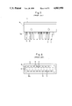
- FIG. 5 is a side view of a composite multihead incorporating a plurality of prior art composite heads shown in FIG. 1;
- FIG. 6 is a bottom view of the composite multihead shown in FIG. 5;
- FIG. 7 is a partial sectional view of the composite multihead shown in FIG. 5;
- FIG. 8 is a perspective view of a composite magnetic and optical head according to a first embodiment of the present invention.
- FIG. 9 is a longitudinal sectional view of the composite head shown in FIG. 8;
- FIG. 10 is an exploded perspective view of the composite head shown in FIG. 8;
- FIG. 11 is a perspective view of a composite magnetic and optical head according to a second embodiment of the present invention.
- FIG. 12 is a longitudinal sectional view of the composite head shown in FIG. 11;
- FIG. 13 is an exploded perspective view of the composite head shown in FIG. 11;
- FIG. 14 is a perspective view of a composite magnetic and optical head according to a third embodiment of the present invention.
- FIG. 15 is an exploded perspective view of the composite head shown in FIG. 14;
- FIG. 16 is a perspective view of a composite magnetic and optical head according to a fourth embodiment of the present invention.
- FIG. 17 is an exploded perspective view of the composite head shown in FIG. 16;
- FIG. 18 is a longitudinal sectional view showing the way a plurality of composite heads shown in FIG. 16 are arranged side by side;
- FIG. 19 is an enlarged sectional view of a principal part near a light transmitting member 22 of the composite magnetic and optical head, illustrating the way a light is propagated when a coating layer having a refractive index higher than that of the member 22 is formed at the interface of the member 22;
- FIG. 20 is an enlarged sectional view of a principal part near a light transmitting member 22 of the composite magnetic and optical head, illustrating the way a light is propagated when a coating layer having a refractive index lower than that of the member 22 is formed at the interface of the member 22;
- FIG. 21 is an enlarged perspective view of the light transmission member 22 of the composite head
- FIG. 22 is a block diagram showing a configuration of a photometric device for measuring an optical loss of an optical sensor of the composite head
- FIG. 23 is a perspective view of a shaping mold for preshaping an optical fiber bundle of the composite head into a predetermined configuration
- FIG. 24 is a perspective view showing a modification of the shaping mold
- FIG. 25 is a perspective view of the optical fiber bundle fitted in the shaping mold of FIG. 24 and subjected to a hardening process such that a coating material, applied to the outer surface of the fiber bundle, is hardened by means of ultraviolet radiation;
- FIG. 26 is an enlarged front view showing the principal part of the optical sensor of the composite head
- FIG. 27 is a perspective view of a composite head in which a light emitting element 15 and a light sensing element 16 of the optical sensor are embedded in apertures 28h of a holder 28;
- FIG. 28 is an exploded longitudinal sectional view of a composite multihead incorporating the composite magnetic and optical heads according to the present invention.
- FIG. 29 is an exploded perspective view of a composite magnetic and optical head incorporated in the composite multihead 11' shown in FIG. 28;
- FIGS. 30 to 33 are process diagrams illustrating steps of end face processing for an optical fiber bundle to be exposed on a rear face 60f of a case (or holder) of the composite multihead 11' shown in FIG. 28;
- FIG. 34 is an exploded perspective view showing the case (or holder) of the composite multihead 11', incorporating a number of composite heads magnetic and optical according to the present invention, and a holder 70 for holding light emitting and sensing elements; and
- FIG. 35 is a perspective view of the composite multihead 11' mounted on a circuit board.
- FIGS. 1 to 7 a prior art composite magnetic and optical head will be described. Throughout the following description, a composite magnetic and optical head is referred to simply as a composite head for ease of description.
- a light transmitting member (optical member) 6 formed of a light transmitting nonmagnetic material is attached to a magnetic detector gap (distal gap) 5 of a magnetic sensor 4, which is formed by winding coils 3 on magnetic cores 2.
- An optical fiber bundle 7, used to read optical data, is connected to the optical member 6, and the magnetic sensor 4 is covered with a bisected holder 8 for holding and fixing the same.
- the optical fiber bundle 7 is divided into two bundles 7a and 7b, which extend outward from the holder 8.
- a light emitting element 15 and a light sensing element 16 are optically coupled to the end faces of fiber bundles 7a and 7b, respectively.
- a record medium such as paper money
- a multihead composed of a plurality of composite heads 1 arranged in a row, as shown in FIG. 4.
- the width of holder 8 is greater than that of the optical member 6 which is attached to the magnetic detector gap 5. Therefore, a gap L is formed between the optical members 6 of each two adjacent composite heads 1, so that it is hard to identify the record medium with high accuracy.
- the heads 1 are put into an outer case 10, as shown in FIGS. 5 and 6.
- a step portion 8b is formed on a side face 8a of the holder 8 of each composite head 1
- the optical fiber bundle 7 is passed through a gap (e.g., about 0.5 mm wide) between the step portion 8b and the outer case 10.
- the fiber bundle 7 is passed through a protective tube 9, and is then drawn out from a bottom face 10a of the outer case 10, as shown in FIGS. 5 and 6.
- numeral 13 designates magnetic terminals or pins each consisting of the distal end portion of a pipe 13a, which is connected to its corresponding lead wire 3a of the magnetic sensor 4, and projects from the bottom face 10a of the outer case 10.
- the multihead 11 In the prior art composite multihead 11, a number of optical fiber bundles 7 and the magnetic pins 13 are disposed mixedly in a narrow space, as shown in FIGS. 6 and 7. At the time of mounting, therefore, the multihead 11 must be handled with the greatest possible care.
- the fiber bundle 7 may possibly be drawn into the holder 8.
- a soldering iron sometimes may touch the protective tubes 9, which project from the outer case 10. If the optical fibers are plastic fibers, in particular, they may be damaged or cut off when they are touched by the soldering iron through the protective tube 9.
- a composite head 1A comprises a magnetic sensor 20 for reading a magnetic pattern, an optical sensor 21 for reading an optical pattern, and a holder 28 for fixing and holding these sensors.
- a magnetic core assembly 25A of the magnetic sensor 20 comprises a pair of cores 25, arranged symmetrically with respect to a plane extending along the distal gap 25c, and coils 32 wound individually on the cores 25.
- the optical sensor 21 includes a light transmitting member (optical member) 22 and an optical fiber bundle 23.
- the optical member 22, which is formed of a light transmitting nonmagnetic material, has the shape of a rectangular prism.
- the fiber bundle 23 includes a number optical fibers whose corresponding ends are coupled in line to the optical member 22.
- the optical member 22, thus coupled with the optical fiber bundle 23, is fitted in the distal gap 25c so as to be held between the paired magnetic cores 25.
- the magnetic sensor 20, holding the optical member 22, is held and fixed by the bisected holder 28.
- the holder 28 is in the form of a case whose top and bottom end walls 28f and 28g and side walls 28b, 28b, extending at right angles to the length of the distal gap 25c of the magnetic sensor 20, are each formed with a rectangular window.
- the holder 28 is divided into two parts substantially symmetrical with respect to a plane extending along the distal gap 25c.
- the magnetic sensor 20 is supported by the holder 28 so that its distal gap 25c projects downward from the bottom end wall 28g of the holder 28.
- the optical fiber bundle 23, which is coupled to the optical member 22, is divided into two bundles 23a and 23b, which extend outward through oval apertures 28h in the top wall of the holder 28, individually.
- a light emitting element and a light sensing element are optically coupled to the end faces of the fiber bundles 23a and 23b, respectively.
- each magnetic core 25 includes a wide portion 25a, which projects downward from the bottom end wall 28g and is not surrounded by the holder 28, in the vicinity of the distal gap 25c, and a narrow portion 21b, which is located inside the bottom end wall 28g so as to be surrounded by the holder 28, and is wound with the coil 32.
- the width of the narrow portion 25b is, for example, half that of the wide portion 25a or of the prior art core.
- the ratio of the magnetic field strength of that portion (narrow portion 25b) of each magnetic core 25 wound with the coil 32 to that obtained in the prior art case is 0.9979 : 1, which indicates hardly any difference.
- the coil 32 can enjoy the same number of turns as its prior art counterpart.
- a plurality of such composite heads 1A are arranged in a row to form a multihead.
- the gaps 25c of the magnetic core assemblies 25A and the optical members 22 of each two adjacent composite heads 1A can be arranged close to one another, without being hindered by their corresponding holders 28.
- the multihead is enabled to identify the record medium with high accuracy. Since the narrow portion 25b of each magnetic core 25 is made narrower, moreover, the size of the composite head 1A can be reduced in proportion.
- a space 29 is defined between the narrow portions 25b of the magnetic cores 25 and the holder 28. Since the narrow portions 25c are narrower than in the conventional case, the space 29 is wider than that of the prior art composite head. With use of this space 29, the optical fiber bundle 23 can be easily drawn out of the holder 28 through the limited space inside the holder 28. At the time of assembling, moreover, the space 29 serves to protect the optical fiber bundle 23 from an undue force.
- FIGS. 11, 12 and 13 show a second embodiment of the present invention.
- a composite head 1B of this embodiment differs from the composite head of the first embodiment only in that its optical fiber bundle 23 is drawn out of a holder 28 through oval apertures 28i in one side wall 28a of the holder 28. More specifically, a pair of apertures 28i are bored through the one side wall 28a of the bisected holder 28 of the second embodiment. The apertures 28i, which open to the space 29, are situated on either side of the narrow portion 25b of each corresponding magnetic core 25. Optical fiber bundles 23a and 23b, passed through the space 29, are drawn out of the holder 28 through their corresponding apertures 28i.
- like reference numerals refer to like portions throughout the drawings.
- FIGS. 14 and 15 show a third embodiment of the present invention.
- a composite head 1C of this embodiment differs from the composite heads of the first and second embodiments only in that its optical fiber bundles 23a and 23b are drawn out of a holder 28 along their corresponding guide grooves 28j, which extend vertically on the outer surfaces of the respective top portions of two opposite side walls 28b, 28b of the holder 28.
- like reference numerals refer to like portions throughout the drawings.
- FIGS. 16, 17 and 18 show a fourth embodiment of the present invention.
- a step portion 28c is formed on one side wall 28b of its holder 28 which extends at right angles to a distal gap 25c of a magnetic sensor 20.
- the step portion 28c extends along the upper and lower side edges of the side wall 28b.
- the upper and lower side edges of the other side wall 28b' are cut, thus forming step portions 28d and 28e.
- a gap W is secured between narrow portions 25'b of magnetic cores 25' of the adjacent composite heads 1D.
- the gap W is narrower than the gap L of the prior art composite heads 1 shown in FIG. 4 by a margin attributable to the step portions 28c, 28d and 28e of the side walls 28b and 28b'. Accordingly, the narrow portion 25'b of each magnetic core 25' need not be narrowed so much as in the cases of the first to third embodiments. In the first to third embodiments, it is necessary only that the narrow portion 25b of the magnetic core 25 be narrower than the wide portion 25a at least by a margin equivalent to the width of the gap L. In the fourth embodiment, on the other hand, the narrow portion 25'b must only be narrower by a margin equivalent to the width of the gap W.
- the side walls 28b and 28b' are formed with the step portions 28c, 28d and 28e, respectively, whereby they can engage each other in a fitted manner such that the distance between each two adjacent magnetic core assemblies 25'A are reduced by (L-W). Moreover, the wide portion 25'a is at least wider than the distance between the side walls 28b and 28b'. Thus, the medium identification accuracy can be improved.
- the optical fiber bundle 23 is drawn out through a guide opening 25'd bored through the central portion of the top wall of the magnetic core assembly 25'A, as shown in FIG. 17.
- the ratio of the magnetic field strength obtained with use of the guide opening 25'd to that obtained in the prior art case is 0.9979 : 1, which indicates hardly any difference, even though the effective magnetic-path sectional area of the opening portion of the core assembly 25'A is half that of its counterpart without the guide opening 25'd.
- the number of turns of the coil 32 need not be increased.
- the magnetic core assembly 25A (25'A) is finally filled with a resin, such as epoxy resin.
- a resin such as epoxy resin.
- the refractive index of an epoxy-based filler material is higher than that of a clad material for optical fibers. If the optical fibers are directly touched by this filler material, therefore, an optical loss increases.
- the resin penetrates into a space between the opposed surfaces of the core assembly 25A (25'A) and the optical member 22 as the light transmitting member.
- the epoxy resin which has a high refractive index, touches the optical member 22, so that a reflected light from the record medium F leaks out through the epoxy resin 50C and both side faces (interfaces) 22a and 22b of the optical member 22, as shown in FIG. 19.
- the sensitivity for optical pattern detection may possibly be lowered.
- At least the interfaces 22a and 22b of the optical member 22, surrounded by points A, D, H and E and points B, C, G and F, respectively, in FIG. 21, are first formed with a coating layer, e.g., an organic molecular layer 50, whose refractive index is lower than that of the optical member 22, as shown in FIGS. 20 and 21.
- a coating layer e.g., an organic molecular layer 50, whose refractive index is lower than that of the optical member 22, as shown in FIGS. 20 and 21.
- FIG. 22 shows a photometric device for detecting the amount of optical loss caused by the formation of the organic molecular layer 50.
- a light beam of 660 nm emitted from an LED is guided by means of a plastic optical fiber 52 of 1.0-mm diameter, and is optically coupled to the optical fiber bundle 23a for incidence of the composite head 1A (1B, 1C or 1D) of the present invention by means of a V-groove connector 53.
- optical loss PO at the outlet end of the optical fiber 52 is 14.5 dBm for the output light of the LED.
- Output P2 of the emission-side optical fiber bundle 23b obtained when the detection surface of the optical member 22 in contact with the record medium is released infinitely, is defined as nonreflective (black), while output P2 obtained when a white paper sheet is in intimate contact with the detection surface of the optical member 22 is defined as totally reflective (white).
- optical loss P2 at the outlet end of the optical fiber 23b of the composite head 1A (1B to 1D), with various organic molecular layers as samples formed at the interfaces 22a and 22b was measured by using the aforesaid photometric device.
- Table 1 shows the measured optical loss (P0-P2).
- Eight plastic optical fibers 23 were arranged on each of the incidence and emission sides to be connected to the respective optical members 22 of the composite heads.
- the optical fibers 23 used have Sendust cores and are 10 cm long.
- the width of each optical member 22 (width of the distal gap 5) is 300 ⁇ m.
- the optical fiber bundle 23 to be fitted in the composite head 1A (1B to 1D) is previously preshaped by means of a shaping mold 55 or 56 shown in FIG. 23 or 24, for example.
- the molds 55 and 56 are suitably used to preshape the optical fibers 23 for the composite heads 1A and 1C shown in FIGS. 8 and 14 and that for the head 1D shown in FIG. 16, respectively.
- the shaping mold 55 has hollows 55a, 55b and 55c, while the shaping mold 56 has hollows 56a and 56b. These hollows are adapted to receive the optical member 22, the junction of the optical member 22 and the optical fiber bundle 23, and the fiber bundle 23 (or bundles 23a and 23b).
- the hollows 55b and 55c of the mold 55 and the hollow 56b of the mold 56 have a suitable shape for the curvature of the optical fiber bundle 23 (or bundles 23a and 23b), e.g., the same configuration as the inside of the composite head or a somewhat smaller shape.
- the fiber bundle 23 is first coated with an unhardened resin coating material, e.g., UV resin (refractive index: 1.43) having a refractive index lower than that (1.53) of epoxy resin which is to be finally filled into the holder 28 of the head 1D.
- an unhardened resin coating material e.g., UV resin (refractive index: 1.43) having a refractive index lower than that (1.53) of epoxy resin which is to be finally filled into the holder 28 of the head 1D.
- the optical member 22 and the junction are fitted into the hollow 56a of the mold 56, and the optical fiber bundle 23 into the hollow 56b.
- the fiber bundle portion is pressed and fixed by means of a quartz plate 57, as shown in FIG. 25.
- UV radiation is applied to the fiber bundle 23, which is coated with the unhardened UV resin, thereby hardening the resin.
- the optical fiber bundle 23 is solidified in the same shape as when it is fitted into the hollow 56b.
- the optical fiber bundle 23 is preshaped into a predetermined configuration, and is then solidified.
- the fiber bundle 23 can be fitted directly into the composite head 1D without being subjected to any undue force. Accordingly, the fiber bundle 23 can be mounted in a short time without damaging the junction between itself and the optical member 22.
- the optical fiber bundle 23 is very easy to handle. Since the outer surface of the fiber bundle 23 is covered with the low-refraction resin, moreover, the filler material, which finally fills the holder 28 of the composite head 1D, cannot directly touch the optical fiber 23. Thus, the optical loss is prevented from increasing.
- optical fibers constituting the optical fiber bundle are plastic fibers, they may alternatively be preshaped by heating. In this case, it is necessary only that the fiber bundle be kept in a furnace of e.g. 90° C. for an hour or thereabout.
- the respective optical losses of the composite head using the UV-coated, preshaped optical fiber bundle 23 and a composite head using an uncoated optical fiber bundle, for use as a control, were measured by means of the photometric device shown in FIG. 22. Table 2 shows the result of the measurement.
- each composite head should preferably be constructed so that the optical fiber bundle is not adapted to be drawn out of the head.
- FIGS. 26 and 27 show a composite head 1A' of a type such that a light emitting element 15 and a light sensing element 16, attached to the end faces of their corresponding optical fiber bundles 23a and 23b, are embedded individually in a pair of apertures 28h of a holder 28.
- the head 1A' includes an optical member 22, the optical fiber bundle 23, and the light emitting and sensing elements 15 and 16.
- the elements 15 and 16 are connected to the respective end faces of the incidence and emission-side optical fiber bundles 23a and 23b of the fiber bundle 23. As shown in FIG.
- the light emitting and sensing elements 15 and 16 are contained in their corresponding apertures 28h bored through the holder 28, and only the lead wires 15a and 16a are drawn out of the composite head 1A', that is, the optical fiber bundle 23 is kept within the head 1A'.
- the fiber arrangement is simple.
- the mounting work is easy because the fiber bundles 23 need not be drawn out of the case 10.
- the fiber bundles are prevented from being touched and burned by a soldering iron.
- the soldering work is facilitated.
- the light emitting and sensing elements 15 and 16 may be fixedly arranged within the space between the case 10 and the step portion 8b on the side face 8a of the holder 8.
- FIG. 28 is a sectional view of a composite head according to the present invention
- FIGS. 34 and 35 show an application of a composite multihead which, incorporating a number of composite heads, is mounted on a circuit board.
- like reference numerals are used to designate like components having substantially the same functions or effects as those of the composite head 1A shown in FIGS. 8 to 10.
- a magnetic sensor 20 of a composite head 1E of this embodiment is wholly surrounded by a case (holder) 60 except the region near its distal gap 25c.
- a number of magnetic sensors 20 are contained in the case 60, thus forming a multihead 11'.
- the gapside portion of a magnetic core assembly 25A of each magnetic sensor 20 is supported by one side face 60a of the case 60, while that end portion of the core assembly 25A on the opposite side thereof to the distal gap 25c is supported by a holder 65.
- the magnetic core assembly 25A is halved, and an opening 25d is formed in the center of the end portion of the core assembly 25A opposite to the distal gap 25c.
- An optical fiber bundle 23 is adapted to be passed through the opening 25d.
- An optical member 22, which is formed of a light transmitting nonmagnetic material, is fitted in the distal gap 25c of the magnetic core assembly 25A.
- One end of the optical fiber bundle 23, formed in line along the gap 25c, is coupled to the back of the optical member 22.
- the fiber bundle 23 is drawn out of the core assembly 25A through the opening 25d.
- the case 60 is composed of a case body 60b, having a substantially U-shaped cross section, and a lid 60c covering the top opening of the case body 60b.
- a through hole 60e is bored through each projection 60d (see FIG. 30).
- a fixing agent 61 such as a two-liquid epoxy resin, is poured into the spaces around the optical fiber bundles 23 a and 23b to fix them in the through holes 60e (see FIG. 31).
- the fiber bundles 23a and 23b, thus fixed in their corresponding holes 60e, are cut along the respective end faces of the projections 60d (FIG. 32).
- the cut end faces of the fiber bundles 23a and 23b are buffed to be smoothed by means of a rotary buffing machine or the like (FIG. 33).
- the other end of the optical fiber bundle is fixed so that the other end face thereof is smoothed and exposed on the rear face 60f of the case 60 opposite to the distal gap 25c.
- each composite head 1E two magnetic pins 63 are planted, at one end thereof, in a terminal board 32b which is fixed, inside the case 60, to that face of the holder 65 opposed to the lid 60c.
- the other end of each magnetic in 63 projects to the outside through its corresponding one of notches 60g cut in each side wall of the case body 60b.
- a lead wire 32a is connected to the one end of each magnetic pin 63.
- Notches 60h are cut in each side edge of the lid 60c, corresponding in position to the notches 60g in the case body 60b.
- the case 60 is mounted on a holder 70 in which the light emitting elements 15 and the light sensing elements 16 are contained and held in position. More specifically, the holder 70 is in the form of a thick board having the same length and width as the case 60, which contains the composite heads 1E. Cylindrical holes 70a, as many as the projections 60d of the case 60, are bored in that face of the holder 70 which is opposed to the rear face 60f of the case 60. These holes 70a, which have a depth substantially equivalent to the height of the projections 60d, are adapted individually to receive the projections 60d. Holes 70b are bored in the opposite face of the holder 70 so as to be coaxial with their corresponding cylindrical holes 70a.
- the holes 70b are adapted to hold the light emitting elements 15 or the light sensing elements 16.
- Each hole 70a communicates with its corresponding hole 70b by means of an aperture 70c which substantially equal in diameter to the through hole 60e of each projection 60d.
- One light emitting element 15 and one light sensing element 16 are fixedly fitted individually in each adjacent pair of holes 70b arranged across the holder 70.
- Grooves 70e which have the same depth as the notches 60h of the case 60, are formed on each side face of the holder 70 so as to extend vertically in alignment with their corresponding notches 60h.
- the case 60, with the composite heads 1E therein, and the holder 70 are first joined together so that the projections 60d are fitted tight in their corresponding holes 70a. Then, the magnetic pins 63 are bent toward the holder 70. In this state, the magnetic pins 63 and terminals 13 and 13' of the light emitting and sensing elements 15 and 16 are inserted into through holes of the circuit board 80, and are soldered therein. Thus, the mounting of the multihead 11' is completed.
- the composite multihead 11' constructed in this manner, goes wrong due to electrical disconnection in any of the light emitting elements 15 or the like, it can be disengaged from the circuit board 80 by melting solder on the board 80. Thereupon, only the holder 70 can be replaced with a new one after it is separated from the case 60. Since the optical fiber bundles 23 are not drawn out of the case 60, the fiber arrangement is simple. At the time of assembling the composite heads 1E, moreover, the optical fibers cannot be touched and burned by a soldering iron. Furthermore, the optical fibers can easily be coupled optically to the holder 70, which contains the light emitting and sensing elements 15 and 16. Thus, the incorporation into the circuit board 80 and the soldering work are facilitated, and the whole structure, as well as the individual components, can be handled very easily.
- the case 60 and the holder 70 are coupled together by fitting the projections 60d of the case 60 into the holes 70a of the holder 70.
- the method of coupling the case 60 and the holder 70, according to the present invention is not limited to this manner.
- the holder may be fixed to the case, by means of screws or the like, in a manner such that the respective exposed end faces of the optical fibers 23 are opposed to the light emitting or sensing elements in the holder, without the use of the projections 60d or the holes 70a.
- Magnetic resistance elements or Hall elements may be used in place of the aforementioned magnetic coils 32 for detecting the magnetic pattern. Instead of utilizing the reflected light, moreover, transmitted light may be used to detect the optical pattern.
Abstract
Description
              TABLE 1
______________________________________
Material of Material of
Optical     High Mol.
Member      Layer
(refractive (refractive
                      PO-P2         Black -
index        index)   Black     White White
______________________________________
1*  Quartz      Epoxy     29.1    24.6  4.5
    (1.46)      (1.53)    28.9    24.6  4.3
                          27.8    23.5  4.3
                          (28.6)  (24.2)
                                        (4.3)
2   Quartz      UV Resin  29.0    23.2  5.8
    (1.46)      (1.43)    28.0    22.5  5.5
                          28.3    22.8  5.5
                          (28.4)  (22.6)
                                        (5.6)
3   Potassium   Epoxy     28.7    22.5  6.2
    Soda Lead   (1.53)    28.3    22.3  6.0
    (1.67)                28.6    23.7  5.9
                          (28.5)  (22.8)
                                        (6.0)
______________________________________
 *: Control
 Parenthesized figures indicate mean values.
              TABLE 2
______________________________________
             PO-P2        Black -
             Black    White   White
______________________________________
4*     No UV Coating
                   28.5       24.3  4.2
                   28.4       24.1  4.3
                   28.9       24.6  4.3
                   (28.6)     (24.3)
                                    (4.3)
5      UV-Coated   28.7       22.7  6.0
                   28.3       23.0  5.7
                   28.3       22.6  5.7
                   (28.4)     (22.8)
                                    (5.8)
______________________________________
 *: Control
 Parenthesized figures indicate mean values.
Claims (17)
Applications Claiming Priority (4)
| Application Number | Priority Date | Filing Date | Title |
|---|---|---|---|
| JP62-126522 | 1987-05-23 | ||
| JP62126522A JP2565904B2 (en) | 1987-05-23 | 1987-05-23 | Magneto-optical composite head with built-in light emitting and receiving elements |
| JP62-126525 | 1987-05-23 | ||
| JP62126525A JP2565905B2 (en) | 1987-05-23 | 1987-05-23 | Magneto-optical composite head |
Publications (1)
| Publication Number | Publication Date |
|---|---|
| US4883950A true US4883950A (en) | 1989-11-28 |
Family
ID=26462696
Family Applications (1)
| Application Number | Title | Priority Date | Filing Date |
|---|---|---|---|
| US07/159,041 Expired - Fee Related US4883950A (en) | 1987-05-23 | 1988-02-22 | Composite magnetic and optical head |
Country Status (2)
| Country | Link |
|---|---|
| US (1) | US4883950A (en) |
| CA (1) | CA1306055C (en) |
Cited By (4)
| Publication number | Priority date | Publication date | Assignee | Title |
|---|---|---|---|---|
| US5930081A (en) * | 1996-10-31 | 1999-07-27 | Mitsumi Electric, Co., Ltd. | Magnetic head holder having protrusion portions thermally fusion-bonded to a magnetic head core |
| US5932868A (en) * | 1996-09-26 | 1999-08-03 | Dresser Industries, Inc. | Cleaning system for a card reader |
| US5963402A (en) * | 1996-07-19 | 1999-10-05 | Minebea Co., Ltd. | Magnetic head and method for producing the same |
| US6538785B1 (en) * | 1997-12-10 | 2003-03-25 | Samsung Electronics Co., Ltd. | Signal transfer apparatus of computer |
Citations (10)
| Publication number | Priority date | Publication date | Assignee | Title |
|---|---|---|---|---|
| US3612835A (en) * | 1969-12-19 | 1971-10-12 | Vendo Co | Combined optical and magnetic transducer |
| US3781834A (en) * | 1971-08-21 | 1973-12-25 | Philips Corp | Reduction cross-talk in double gap head |
| US4029944A (en) * | 1976-04-07 | 1977-06-14 | Addressograph Multigraph Corporation | Data transducer |
| US4041279A (en) * | 1975-08-04 | 1977-08-09 | Addressograph Multigraph Corporation | Data reading device |
| US4056712A (en) * | 1976-06-09 | 1977-11-01 | Addressograph Multigraph Corporation | Wear compensating optical/magnetic transducer |
| US4085430A (en) * | 1974-01-24 | 1978-04-18 | U.S. Philips Corporation | Thin film magnetic head with a gap formed between a loop shaped core part and a bridging core part |
| US4405959A (en) * | 1980-03-11 | 1983-09-20 | L.C.C.-C.I.C.E. Compagnie Europeenne De Composants Electroniques | Magnetic head for recording and reading magnetic data with variable track width |
| US4574190A (en) * | 1981-12-21 | 1986-03-04 | Omron Tateisi Electronics Co. | Verifying system |
| JPS61125763A (en) * | 1984-11-20 | 1986-06-13 | Okamoto Kosaku Kikai Seisakusho:Kk | Diagonal feed device of optical system copying grinding machine |
| US4719527A (en) * | 1984-10-31 | 1988-01-12 | Sanyo Electric Co., Ltd. | Composite magnetic head having accurately aligned gaps |
-
1988
- 1988-02-22 US US07/159,041 patent/US4883950A/en not_active Expired - Fee Related
- 1988-02-23 CA CA000559519A patent/CA1306055C/en not_active Expired - Fee Related
Patent Citations (10)
| Publication number | Priority date | Publication date | Assignee | Title |
|---|---|---|---|---|
| US3612835A (en) * | 1969-12-19 | 1971-10-12 | Vendo Co | Combined optical and magnetic transducer |
| US3781834A (en) * | 1971-08-21 | 1973-12-25 | Philips Corp | Reduction cross-talk in double gap head |
| US4085430A (en) * | 1974-01-24 | 1978-04-18 | U.S. Philips Corporation | Thin film magnetic head with a gap formed between a loop shaped core part and a bridging core part |
| US4041279A (en) * | 1975-08-04 | 1977-08-09 | Addressograph Multigraph Corporation | Data reading device |
| US4029944A (en) * | 1976-04-07 | 1977-06-14 | Addressograph Multigraph Corporation | Data transducer |
| US4056712A (en) * | 1976-06-09 | 1977-11-01 | Addressograph Multigraph Corporation | Wear compensating optical/magnetic transducer |
| US4405959A (en) * | 1980-03-11 | 1983-09-20 | L.C.C.-C.I.C.E. Compagnie Europeenne De Composants Electroniques | Magnetic head for recording and reading magnetic data with variable track width |
| US4574190A (en) * | 1981-12-21 | 1986-03-04 | Omron Tateisi Electronics Co. | Verifying system |
| US4719527A (en) * | 1984-10-31 | 1988-01-12 | Sanyo Electric Co., Ltd. | Composite magnetic head having accurately aligned gaps |
| JPS61125763A (en) * | 1984-11-20 | 1986-06-13 | Okamoto Kosaku Kikai Seisakusho:Kk | Diagonal feed device of optical system copying grinding machine |
Cited By (4)
| Publication number | Priority date | Publication date | Assignee | Title |
|---|---|---|---|---|
| US5963402A (en) * | 1996-07-19 | 1999-10-05 | Minebea Co., Ltd. | Magnetic head and method for producing the same |
| US5932868A (en) * | 1996-09-26 | 1999-08-03 | Dresser Industries, Inc. | Cleaning system for a card reader |
| US5930081A (en) * | 1996-10-31 | 1999-07-27 | Mitsumi Electric, Co., Ltd. | Magnetic head holder having protrusion portions thermally fusion-bonded to a magnetic head core |
| US6538785B1 (en) * | 1997-12-10 | 2003-03-25 | Samsung Electronics Co., Ltd. | Signal transfer apparatus of computer |
Also Published As
| Publication number | Publication date |
|---|---|
| CA1306055C (en) | 1992-08-04 |
Similar Documents
| Publication | Publication Date | Title |
|---|---|---|
| US5732167A (en) | Optical fiber sensor for measuring a magnetic field or electric current and method for making the same | |
| US4883950A (en) | Composite magnetic and optical head | |
| JPS6265004A (en) | Optical fiber centering apparatus during welding | |
| US7394952B1 (en) | Optical transmission device and optical module | |
| JPH02280104A (en) | Connecting terminal mount | |
| US4118747A (en) | Composite magnetic head | |
| CN100376909C (en) | Optical device, optical transceiver and other optical apparatuses using the optical device | |
| CA2056850C (en) | Optical sensor | |
| JP2534289B2 (en) | Magneto-optical composite head | |
| JPH03130706A (en) | Optical module | |
| JP3067109B1 (en) | Optical component and optical fiber terminal structure | |
| JP3543319B2 (en) | Ferrule for optical connector | |
| JP2565948B2 (en) | Magneto-optical composite head | |
| JPH08179162A (en) | Multi-fiber optical connector | |
| JPH0862452A (en) | Master plug for multi-core optical connector inspection and manufacture thereof | |
| JP2773922B2 (en) | Contact type optical sensor | |
| JP2565904B2 (en) | Magneto-optical composite head with built-in light emitting and receiving elements | |
| CA2336388C (en) | Ferrule for a pluggable optical connection | |
| KR900006052Y1 (en) | Floating magnetic head | |
| JP2651116B2 (en) | Transmission type magnetic and optical sensors | |
| JPH0411232Y2 (en) | ||
| JPH08262266A (en) | Method for aligning optical waveguide | |
| JP5398409B2 (en) | Optical connector | |
| JP2598499B2 (en) | Optical fiber spacing measurement method | |
| JP2009053365A (en) | Optical connector |
Legal Events
| Date | Code | Title | Description |
|---|---|---|---|
| AS | Assignment |
Owner name: FURUKAWA ELECTRIC CO., LTD., THE, NO. 6-1, MARUNOU Free format text: ASSIGNMENT OF ASSIGNORS INTEREST.;ASSIGNORS:CHIBA, KAZUO;OHISHI, YOSHIAKI;MIGITA, JITUO;AND OTHERS;REEL/FRAME:004844/0810 Effective date: 19880212 Owner name: FURUKAWA ELECTRIC CO., LTD., THE, A CORP. OF JAPA Free format text: ASSIGNMENT OF ASSIGNORS INTEREST;ASSIGNORS:CHIBA, KAZUO;OHISHI, YOSHIAKI;MIGITA, JITUO;AND OTHERS;REEL/FRAME:004844/0810 Effective date: 19880212 |
|
| FEPP | Fee payment procedure |
Free format text: PAYOR NUMBER ASSIGNED (ORIGINAL EVENT CODE: ASPN); ENTITY STATUS OF PATENT OWNER: LARGE ENTITY |
|
| FPAY | Fee payment |
Year of fee payment: 4 |
|
| FPAY | Fee payment |
Year of fee payment: 8 |
|
| REMI | Maintenance fee reminder mailed | ||
| LAPS | Lapse for failure to pay maintenance fees | ||
| STCH | Information on status: patent discontinuation |
Free format text: PATENT EXPIRED DUE TO NONPAYMENT OF MAINTENANCE FEES UNDER 37 CFR 1.362 |
|
| FP | Lapsed due to failure to pay maintenance fee |
Effective date: 20011128 |