US4883409A - Pumping apparatus for delivering liquid at high pressure - Google Patents
Pumping apparatus for delivering liquid at high pressure Download PDFInfo
- Publication number
- US4883409A US4883409A US07/246,479 US24647988A US4883409A US 4883409 A US4883409 A US 4883409A US 24647988 A US24647988 A US 24647988A US 4883409 A US4883409 A US 4883409A
- Authority
- US
- United States
- Prior art keywords
- piston
- pump
- pumping apparatus
- liquid
- pistons
- Prior art date
- Legal status (The legal status is an assumption and is not a legal conclusion. Google has not performed a legal analysis and makes no representation as to the accuracy of the status listed.)
- Expired - Lifetime
Links
Images


Classifications
-
- F—MECHANICAL ENGINEERING; LIGHTING; HEATING; WEAPONS; BLASTING
- F04—POSITIVE - DISPLACEMENT MACHINES FOR LIQUIDS; PUMPS FOR LIQUIDS OR ELASTIC FLUIDS
- F04B—POSITIVE-DISPLACEMENT MACHINES FOR LIQUIDS; PUMPS
- F04B49/00—Control, e.g. of pump delivery, or pump pressure of, or safety measures for, machines, pumps, or pumping installations, not otherwise provided for, or of interest apart from, groups F04B1/00 - F04B47/00
- F04B49/20—Control, e.g. of pump delivery, or pump pressure of, or safety measures for, machines, pumps, or pumping installations, not otherwise provided for, or of interest apart from, groups F04B1/00 - F04B47/00 by changing the driving speed
-
- F—MECHANICAL ENGINEERING; LIGHTING; HEATING; WEAPONS; BLASTING
- F04—POSITIVE - DISPLACEMENT MACHINES FOR LIQUIDS; PUMPS FOR LIQUIDS OR ELASTIC FLUIDS
- F04B—POSITIVE-DISPLACEMENT MACHINES FOR LIQUIDS; PUMPS
- F04B11/00—Equalisation of pulses, e.g. by use of air vessels; Counteracting cavitation
- F04B11/005—Equalisation of pulses, e.g. by use of air vessels; Counteracting cavitation using two or more pumping pistons
- F04B11/0058—Equalisation of pulses, e.g. by use of air vessels; Counteracting cavitation using two or more pumping pistons with piston speed control
-
- F—MECHANICAL ENGINEERING; LIGHTING; HEATING; WEAPONS; BLASTING
- F04—POSITIVE - DISPLACEMENT MACHINES FOR LIQUIDS; PUMPS FOR LIQUIDS OR ELASTIC FLUIDS
- F04B—POSITIVE-DISPLACEMENT MACHINES FOR LIQUIDS; PUMPS
- F04B11/00—Equalisation of pulses, e.g. by use of air vessels; Counteracting cavitation
- F04B11/005—Equalisation of pulses, e.g. by use of air vessels; Counteracting cavitation using two or more pumping pistons
- F04B11/0075—Equalisation of pulses, e.g. by use of air vessels; Counteracting cavitation using two or more pumping pistons connected in series
-
- F—MECHANICAL ENGINEERING; LIGHTING; HEATING; WEAPONS; BLASTING
- F04—POSITIVE - DISPLACEMENT MACHINES FOR LIQUIDS; PUMPS FOR LIQUIDS OR ELASTIC FLUIDS
- F04B—POSITIVE-DISPLACEMENT MACHINES FOR LIQUIDS; PUMPS
- F04B49/00—Control, e.g. of pump delivery, or pump pressure of, or safety measures for, machines, pumps, or pumping installations, not otherwise provided for, or of interest apart from, groups F04B1/00 - F04B47/00
- F04B49/06—Control using electricity
- F04B49/065—Control using electricity and making use of computers
-
- F—MECHANICAL ENGINEERING; LIGHTING; HEATING; WEAPONS; BLASTING
- F04—POSITIVE - DISPLACEMENT MACHINES FOR LIQUIDS; PUMPS FOR LIQUIDS OR ELASTIC FLUIDS
- F04B—POSITIVE-DISPLACEMENT MACHINES FOR LIQUIDS; PUMPS
- F04B49/00—Control, e.g. of pump delivery, or pump pressure of, or safety measures for, machines, pumps, or pumping installations, not otherwise provided for, or of interest apart from, groups F04B1/00 - F04B47/00
- F04B49/12—Control, e.g. of pump delivery, or pump pressure of, or safety measures for, machines, pumps, or pumping installations, not otherwise provided for, or of interest apart from, groups F04B1/00 - F04B47/00 by varying the length of stroke of the working members
-
- F—MECHANICAL ENGINEERING; LIGHTING; HEATING; WEAPONS; BLASTING
- F04—POSITIVE - DISPLACEMENT MACHINES FOR LIQUIDS; PUMPS FOR LIQUIDS OR ELASTIC FLUIDS
- F04B—POSITIVE-DISPLACEMENT MACHINES FOR LIQUIDS; PUMPS
- F04B2201/00—Pump parameters
- F04B2201/12—Parameters of driving or driven means
- F04B2201/1208—Angular position of the shaft
-
- F—MECHANICAL ENGINEERING; LIGHTING; HEATING; WEAPONS; BLASTING
- F04—POSITIVE - DISPLACEMENT MACHINES FOR LIQUIDS; PUMPS FOR LIQUIDS OR ELASTIC FLUIDS
- F04B—POSITIVE-DISPLACEMENT MACHINES FOR LIQUIDS; PUMPS
- F04B2205/00—Fluid parameters
- F04B2205/05—Pressure after the pump outlet
-
- F—MECHANICAL ENGINEERING; LIGHTING; HEATING; WEAPONS; BLASTING
- F04—POSITIVE - DISPLACEMENT MACHINES FOR LIQUIDS; PUMPS FOR LIQUIDS OR ELASTIC FLUIDS
- F04B—POSITIVE-DISPLACEMENT MACHINES FOR LIQUIDS; PUMPS
- F04B2207/00—External parameters
- F04B2207/04—Settings
- F04B2207/041—Settings of flow
-
- G—PHYSICS
- G01—MEASURING; TESTING
- G01N—INVESTIGATING OR ANALYSING MATERIALS BY DETERMINING THEIR CHEMICAL OR PHYSICAL PROPERTIES
- G01N30/00—Investigating or analysing materials by separation into components using adsorption, absorption or similar phenomena or using ion-exchange, e.g. chromatography or field flow fractionation
- G01N30/02—Column chromatography
- G01N30/26—Conditioning of the fluid carrier; Flow patterns
- G01N30/28—Control of physical parameters of the fluid carrier
- G01N30/32—Control of physical parameters of the fluid carrier of pressure or speed
- G01N2030/322—Control of physical parameters of the fluid carrier of pressure or speed pulse dampers
-
- G—PHYSICS
- G01—MEASURING; TESTING
- G01N—INVESTIGATING OR ANALYSING MATERIALS BY DETERMINING THEIR CHEMICAL OR PHYSICAL PROPERTIES
- G01N30/00—Investigating or analysing materials by separation into components using adsorption, absorption or similar phenomena or using ion-exchange, e.g. chromatography or field flow fractionation
- G01N30/02—Column chromatography
- G01N30/26—Conditioning of the fluid carrier; Flow patterns
- G01N30/28—Control of physical parameters of the fluid carrier
- G01N30/32—Control of physical parameters of the fluid carrier of pressure or speed
- G01N2030/324—Control of physical parameters of the fluid carrier of pressure or speed speed, flow rate
-
- G—PHYSICS
- G01—MEASURING; TESTING
- G01N—INVESTIGATING OR ANALYSING MATERIALS BY DETERMINING THEIR CHEMICAL OR PHYSICAL PROPERTIES
- G01N30/00—Investigating or analysing materials by separation into components using adsorption, absorption or similar phenomena or using ion-exchange, e.g. chromatography or field flow fractionation
- G01N30/02—Column chromatography
- G01N30/26—Conditioning of the fluid carrier; Flow patterns
- G01N30/28—Control of physical parameters of the fluid carrier
- G01N30/32—Control of physical parameters of the fluid carrier of pressure or speed
- G01N2030/326—Control of physical parameters of the fluid carrier of pressure or speed pumps
-
- G—PHYSICS
- G01—MEASURING; TESTING
- G01N—INVESTIGATING OR ANALYSING MATERIALS BY DETERMINING THEIR CHEMICAL OR PHYSICAL PROPERTIES
- G01N30/00—Investigating or analysing materials by separation into components using adsorption, absorption or similar phenomena or using ion-exchange, e.g. chromatography or field flow fractionation
- G01N30/02—Column chromatography
- G01N30/26—Conditioning of the fluid carrier; Flow patterns
- G01N30/28—Control of physical parameters of the fluid carrier
- G01N30/34—Control of physical parameters of the fluid carrier of fluid composition, e.g. gradient
Definitions
- the invention relates to a pumping apparatus for delivering liquid at a high pressure, in particular a pumping apparatus for solvent delivery in liquid chromatography.
- a pumping apparatus for solvent delivery in liquid chromatography.
- Such a pumping apparatus is used, e.g., in liquid chromatography to pump the mobile phase (solvents or mixtures of solvents) through the chromatographic system including the separation column.
- the pumping apparatus forms a part of the solvent delivery system which may comprise additional units for drawing in and for mixing solvents.
- the flow rate of the liquid delivered to the column is adjustable over a wide range of flow rates. It is furthermore desirable that the solvent delivery system permits the generation of mixtures of solvents and to change the mixing ratio of the various solvents of the mixture in the course of time (gradient operation). Such versatility of the solvent delivery system permits to optimize the analysis conditions for the specific sample to be chromatographically separated.
- the flow rate should be adjustable, it is very important that a once adjusted flow rate is kept as constant as possible. If the flow rate through the separation column would fluctuate, variations in the retention time of the examined sample would occur so that the areas of the chromatographic peaks produced by a detector connected to the outlet of the column, e.g., an absorption detector, a fluorescence detector, or a refractive index detector, would vary. Since the peak areas are representative for the concentration of the chromatographically separated sample substances, fluctuations in the flow rate would impair the accuracy and the reproducibility of quantitative measurements.
- a detector connected to the outlet of the column e.g., an absorption detector, a fluorescence detector, or a refractive index detector
- Some pumping systems like reciprocating pumps with a single piston have inherent flow variations because the piston delivers only during a portion of a pump cycle.
- a dual piston pump having two interconnected pump heads each with a reciprocating piston.
- the pistons are driven via cams and a cam-shaft with a predetermined phase difference so that the resulting outflow is comparatively smooth.
- Such a dual piston pump driven via cams and a common cam shaft is known from U.S. Pat. No. 4,352,636.
- control means are provided which are coupled to the drive means reciprocating the pistons, the control means being operative to adjust the stroke lengths of the pistons between their top dead centre and their bottom dead centre, respectively, permitting an adjustment of the amounts of liquid displaced by the first and second piston, respectively, during a pump cycle such that pulsations in the flow of the liquid delivered to the output of the pumping apparatus are reduced.
- the flow rate is changed by changing the frequency of reciprocation of the pistons so that the pistons move at a higher frequency when a higher flow rate is selected, whereas the stroke volume remains the same when the flow rate is altered.
- the flow rate is changed by changing both the frequency of reciprocation of the pistons and the stroke volume.
- the stroke volume is decreased with the flow rate.
- the pumping apparatus can not only be used in an isocratic solvent delivery system wherein the input of the pumping apparatus is permanently connected to only one solvent container such that only one type of solvent can be used in the chromatographic analysis, but also in applications wherein mixtures of solvents have to be produced, for example in gradient operation.
- a known per-se mixing valve having a plurality of inputs coupled to different solvent containers can be connected with its output to the input of the pumping apparatus.
- the mixing valve is controlled such as to establish selectable connections to a solvent container, respectively, in order to produce the desired solvent mixture so that the selected solvent is drawn in when the first piston is retracted.
- the stroke volume is reduced at small flow rates, the amounts of liquid drawn in during each intake stroke for producing a specific mixing ratio are smaller than in conventional pumps. Due to the smaller packages of liquid drawn in, the pump according to the invention ensures a better mixing of the different solvents sucked in than known pumps. Consequently, an additional mixing chamber as it is used in prior art solvent delivery systems between the output of the pumping apparatus and the input of the separation column is either unnecessary or, at least, a much smaller mixing chamber can be employed so that the unwanted dead volume introduced by such a chamber is substantially reduced. Furthermore, faster gradient changes become possible.
- the driving of the pistons can be accomplished by using any drive means which permits the adjustment of the stroke lengths of the pistons.
- the pistons are coupled to ball-screw drives which translate the rotary motion of the spindles into a linear motion of the pistons.
- the stroke volumes can easily be changed by changing the angle through which the spindles are rotated during a pump cycle.
- a ball-screw drive permits to select any desired displacement/time function for the motion of the pistons during a pump cycle, for example a linear variation of the piston displacement as a function of time or a motion with a pre-compression phase during which a piston is accelerated for a short time. This flexibility is an advantage over prior art pumps which would require a new set of specially designed cams for each new displacement/time function for the piston motion.
- the ball-screw drives may either be coupled via gears to a common drive motor, or each ball-screw drive may be coupled to a different drive motor so that an independent operation of the two pistons is permitted. If two separate drive motors are used, it is possible to precompress the aspirated solvent with the first piston before the second piston has finished its delivery stroke.
- the transmission of the driving force to each piston can advantageously be accomplished via a ball which can move freely in a recess of an actuating element coupled to the rest of the drive means, e.g. a ball-screw-drive, with the ball contacting a piston holder to which the piston is fixed. Since there is no rigid connection between the drive means and the piston, tilt of the piston can be avoided, resulting in an increased lifetime of the seals of the pump chambers.
- a damping unit for damping any remaining flow variations in the outflow of the pump is coupled to the output of the second pump chamber.
- FIG. 1 schematically shows a solvent delivery system for a liquid chromatograph incorporating the pumping apparatus according to the invention.
- FIG. 1A is an alternate embodiment of the apparatus of FIG. 1.
- FIG. 2 is a detailed view of the coupling between the piston and the drive mechanism of the pumping apparatus according to FIG. 1.
- FIG. 3 is a graphical representation of the path travelled by the first piston in a pumping apparatus according to the invention plotted against time for two different stroke volumes.
- FIG. 4 is a graphical representation of the stroke volume displaced by the first piston in a pump according to the invention plotted against flow rate.
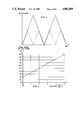
- FIG. 5 is a graphical representation of the frequency of reciprocation of the pistons in a pumping apparatus according to the invention and in a conventional pump having a constant stroke volume.
- FIG. 6 is a graphical representation of the percent pulsation of the output flow in a pumping apparatus according to the invention and in a conventional pump having a constant stroke volume.
- FIG. 7 is a graphical representation for gradient operation illustrating the change of the solvent composition as a function of time for a pumping apparatus in accordance with the invention and for a pump with a fixed stroke volume.
- FIG. 1 there is shown a solvent delivery system according to the present invention for a liquid chromatograph.
- Capillary tubes 1a, 1b, 1c, and 1d are connected with one end to solvent containers represented by the letters A, B, C, and D, respectively, and with the other end to a mixing valve 2.
- the mixing valve 2 has an output capillary 3 which is connected to an inlet valve 4 of the first pump chamber.
- the mixing valve 2 can be operated such that its output capillary 3 is connected to a selected input capillary 1a, or 1b, 1c, or 1d to permit flow of a selected solvent to the first pump chamber.
- a desired solvent composition can be generated.
- the switching of the mixing valve is accomplished by one or several solenoids (not shown) under the control of a control circuitry which is explained below in more detail.
- the mixing valve is shown to have four input capillaries, but it is understood that a mixing valve having any number of input capillaries could be used.
- the inlet valve 4 is an active valve which can be closed or opened by a solenoid 5 under the control of the control circuitry. Instead of the active inlet valve 4 according to FIG. 1, a conventional check valve could also be employed.
- An inlet capillary 6 connects the output of the inlet valve 4 to the input of the pumping system.
- the pumping system comprises two substantially identical pump units which are connected in series, each unit being designed as a piston pump.
- the first pump unit comprises a pump chamber 7 having a cylindrical inner bore 8 for receiving a piston and a corresponding sapphire piston 10 for reciprocating movement inside the cylindrical bore 8.
- the pump chamber 7 has an inlet bore 9 at its lower end through which liquid supplied through the capillary 6 can flow into the cylindrical bore of the first pump chamber.
- the inlet bore 9 is located such that it is closer to the bottom dead centre than to the top dead centre of the piston 10.
- the outer diameter of the piston 10 is smaller than the inner diameter of the bore 8 of the pump chamber so that liquid can flow in the gap between the piston 10 and the inner surface of the bore 8.
- a seal 11 is provided at the bottom of the pump chamber 7 for sealing off the chamber at the opening through which the piston moves into the chamber so that no liquid can reach the outside.
- the pump chamber 7 has an outlet bore at its top through which liquid can leave the first pump unit.
- the outlet bore is connected via a capillary 12 to an outlet valve 13 which can be, for example, a conventional check valve.
- the valve 13 permits liquid to flow only in a direction away from the first pump unit and inhibits flow of liquid in the opposite direction.
- a capillary 14 connects the valve 13 to the inlet of the second pump unit.
- the second pump unit comprises a pump chamber 18 having a cylindrical bore 19 for receiving a piston, a lateral inlet bore at the same relative location as the inlet bore of the first pump chamber, an outlet bore at the top of the chamber and a sapphire piston 20 for reciprocating movement inside the bore 19 of the chamber 18.
- the chamber 18 is sealed off by a seal 21 to avoid that any liquid leaves the chamber through the opening through which the piston extends into bore 19.
- the aforementioned components of the second pump unit thus have the same design as the corresponding components of the first pump unit.
- the outlet of the second pump unit is connected via a capillary 22 to a damping unit 23 which serves for damping any pressure and flow variations which might occur in the outflow of the second pump unit.
- a damping unit 23 which serves for damping any pressure and flow variations which might occur in the outflow of the second pump unit.
- a high pressure damper of the type is used which is known from DE-PS 33 06 631.
- This damper comprises two chambers separated by an elastic partition, with the first chamber receiving the fluid to be damped and the second chamber containing a compressible liquid such as water and a solid ceramic block which compensates for the different coefficients of expansion of the compressible medium and the housing of the second chamber.
- An integral component of the damping unit 23 is a sensor for measuring the pressure of the delivered liquid.
- the output of the damping unit 23 is connected via a capillary 24 to the subsequent chromatographic system (separation column etc.) where the separation of the substances to be analyzed takes place.
- the damping unit can be arranged between the two pump units such that the input port of the damping unit is connected to the outlet valve 13 and that its output port is connected to the inlet of the second pump unit. All the other components of the pumping apparatus as well as the operation of the apparatus would be the same as in the embodiment shown in FIG. 1.
- the sapphire pistons 10, 20 of the two pump units are driven by using a ball-screw drive for each piston.
- the lower ends of the piston 10, 20 are attached to piston holders 25, 26, respectively, and the piston holders are coupled via balls 27, 28 and actuators 37, 48 to recirculating ball spindles 30, 31, respectively.
- return springs 15 and 29 are also provided.
- the ball-screw drives 30, 31 are coupled to toothed gears 33 and 34, respectively.
- the gears 33 and 34 are mating and gear 33 is coupled to a third gear 32 which is fixed to the shaft of a drive motor 36.
- the proportions of the toothed gears 33 and 34 are selected such that gear 34 performs two revolutions when gear 33 performs one revolution.
- a digital indicator 35 for the angular position of the motor 36 is provided which permits to precisely determine the position of the pistons from the transmission ratios of the gears and the ball-screw drives.
- a separate motor 36' may be coupled via gears 32' and 33' to piston 10, allowing an adjustment of the relative phase of the reciprocating motions of the first piston 10 and the second piston 20.
- FIG. 2 is a detailed view of a part of the first pump unit of the pumping apparatus shown in FIG. 1.
- An actuator 37 which is rigidly connected to the ball-screw drive 30 comprises a recess 38 for receiving a ball 27.
- the ball 27 is free to move in the recess 38.
- the top of the ball 27 contacts the piston holder 25 connected to the piston 10.
- the piston is guided by a guiding element 39.
- the guiding element 39 is mounted to a mounting element 40 which is connected to the pump chamber 7.
- a return spring 15 is connected with one of the its ends to the pump chamber and with its other end to the piston holder 25. The return spring 15 pulls the piston downwards when the actuator 37 moves downwards.
- control circuitry of the pumping apparatus of the invention is described with reference to FIG. 1.
- a system controller 41 controls the function of the pumping apparatus in response to inputs made by a user via a user interface 42 coupled to the system controller.
- the user interface 42 can be any known input device, e.g., a keyboard.
- the user may input via the user interface 42, for example, a desired flow rate or a desired solvent mixture or a desired solvent gradient.
- a pump drive controller 43 is connected to the system controller 41.
- a control loop for controlling the movement of the motor 36 is indicated by block 44.
- the actual value for the position of the motor 36 to be used in the control loop 44 is provided from the angular position indicator 35 and the nominal value is provided from the pump drive controller 43.
- a gradient controller 45 which supplies control signals via line 51 to the mixing valve 2 dependent on a desired solvent gradient selected by a user via user interface 42.
- the control signals permit a switching of the mixing valve 2 such that liquid can flow from one of the solvent containers A,B,C, or D through the valve to the first pump unit.
- An inlet controller 46 coupled to the system controller 41 controls the opening and the closing of the inlet valve 4 in coordination with the movement of the piston 10.
- the control signals are supplied to the solenoid 5 on a line 52.
- the pressure of the delivered liquid is measured by a pressure transducer arranged in the damping unit 23.
- the analog output signal of the pressure transducer is supplied on a line 53 to an A/D-converter 47 by which it is converted into a digital signal.
- This digital signal is supplied to the system controller 41 from which it can be passed to the user interface 42 and displayed.
- the operation of the pump is described in two modes of operation, respectively, namely in the isocratic mode and in the gradient mode.
- one of the solvent containers A,B,C, or D is permanently connected to the inlet valve 4 so that always the same solvent is delivered. This can be accomplished either by holding the switching state of the mixing valve 2 fixed at one position so that its output is permanently connected to the same solvent container, or, alternatively, by operating the solvent delivery system without a mixing valve, so that one of the containers A,B,C, or D is directly connected to the input valve 4 without an intermediate mixing valve.
- the top dead centre of the movement of the first piston 10 is determined. Under the control of the control circuitry, the first piston 10 slowly moves upwards into the bore 8 of the piston chamber until the piston holder 25 abuts the lower end of the pump chamber 7. Once this end position has been reached, the piston 10 moves back a predetermined path length.
- This position of the piston is defined as the top dead centre and the corresponding angular setting of the motor 36 determined by the indicator 35 is stored as a digital value in the control circuitry.
- the top dead centre can always be accurately reproduced by providing the motor control loop 44 with this digital value as a nominal value.
- the pump starts with its normal operation.
- the inlet valve 4 is opened by the solenoid 5 under the control of the inlet controller 46 and the piston 10 moves down from the top dead centre, thereby sucking solvent into the first pump chamber.
- the stroke length i.e., the distance the piston travels between its top dead centre and its bottom dead centre is dependent on the flow rate which a user has selected at the user interface 42. From the information about the desired flow rate passed from the user interface 42 to the system controller 41, the system controller 41 computes the corresponding stroke length using a predetermined mathematical relationship between flowrate and stroke length (or stroke volume, which is proportional to the stroke length).
- the drive motor 36 is stopped and the inlet valve 4 is closed so that no more liquid can flow into the first pump unit. Then, the motor 36 is restarted, now moving in the opposite direction as before until it again reaches the top dead centre. Then, the sequence starts anew with the piston moving down from the top dead centre to the bottom dead centre. Since the two pistons 10 and 20 are rigidly coupled to each other via gears 33 and 34, the second piston 20 operates with a fixed phase difference relative to the first piston 10. This phase difference is 180 degrees. As a consequence of the 180 degrees phase shift, the second piston 20 delivers liquid when the first piston 10 sucks in liquid and vice versa.
- the first piston 10 moves twice the path of the second piston 20 at any angular step of the motor 36.
- the second piston sucks in half of the volume displaced by the first piston and during the suction stroke of the first piston, the second piston delivers the volume sucked in in the preceding half-cycle.
- the volume V1 is delivered to the output of the pumping apparatus.
- the output of the second pump unit is connected to the damping unit 23 which serves for compensating for the delay in delivery at the beginning of the delivery phase of the first piston.
- FIG. 3 shows a displacement-time diagram for the movement of the first piston 10, assuming a specified fixed flow rate.
- the horizontal axis is the time axis and the vertical axis is the axis for the displacement of the piston.
- the displacement-time diagram of FIG. 3 illustrates the preferred embodiment of the present invention that the paths travelled by the pistons are linear functions of time with two exemplary cases: in the first case, represented by the solid lines, the stroke length or stroke volume is twice as large as the stroke length or stroke volume in the second case, illustrated by the dashed lines. In both cases, the same amount of liquid is delivered within a specified time interval so that the resulting flow rates are identical.
- the dashed curve has twice the frequency of the solid curve because the stroke path or stroke volume corresponding to the dashed curve is only half the stroke volume corresponding to the solid curve and the resulting flow rate is the same in both cases.
- FIG. 4 shows an example how the stroke volume for the first piston 10 is varied with the flow rate of the delivered liquid.
- the relationship shown can be stored, for example, in the form of digital values in the system controller 41. It can be seen from FIG. 4 that, except for a small range of flow rates near zero, the stroke volume for the first piston is increased linearly with the flow rate, that means the plot of stroke length versus flow rate is a straight line. At very small flow rates below about 0,1 ml/min, the stroke volume is kept at a constant value down to zero flow rate. It is understood that the relationship plotted in FIG. 4 is not the only one possible but that various modifications thereto are possible, whereby it is preferred that the stroke volume is decreased when the flow rate is decreased.
- the curve labelled "a” depicts the variation of the frequency of reciprocation of the pistons (pump frequency) with the flow rate assuming that the stroke volume is changed with the flow rate according to the function shown in FIG. 4.
- the pump frequency for each selected flow rate is determined by the system controller 41.
- the curve labelled “b” depicts the variation of the pump frequency with the flow rate for a prior art pumping apparatus having a fixed stroke volume of 100 microliters. Since, according to the invention, the stroke volume is changed with the flow rate, the pump frequency is a more complicated function of the flow rate than the straight line "b" of the prior art wherein the flow rate is increased by linearly increasing the pump frequency.
- the pump frequency in a pumping apparatus according to the invention is larger than in the prior art pump. Since the pump frequency is larger, an remaining pulsations in the outflow of the pumping apparatus also occur with a higher frequency so that the ripple in the output signal of a detector coupled to the separation column has higher frequency than in prior art devices. Such an increase of the ripple frequency is advantageous with regard to accuracy and reproducibility of the chromatographic measuring results.
- FIG. 6 illustrates the effect of a variable stroke volume on the pump pulsations.
- the horizontal axis of the diagram is the flow rate and the vertical axis of the diagram is the pump pulsation P in percent.
- the pump pulsation is defined in terms of pressure, but with the assumption of laminar flow of the liquid, this is equivalent to a definition in terms of flow rate.
- curve "c” depicts the percent pulsation for a pumping apparatus according to the invention incorporating a relationship between flow rate and stroke volume as shown in FIG. 4, and curve “d " depicts the percent pulsation for a prior art pump having a constant stroke volume of 100 microliters. It can be seen that the invention leads to a substantial reduction of the percent pump pulsation.
- a mixing valve 2 connected to different solvent containers A,B,C, and D is required.
- the mixing valve 2 is controlled during the intake stroke of the first piston 10 such that a specified solvent container is connected to the pump input for a certain fraction of the whole stroke path of the first piston. This fraction is calculated in the system controller 41 from the desired mixing ratio of the different solvents.
- the following example is to illustrate this situation:
- the system controller 41 computes, taking into account the stroke length for the present flow rate, the positions of the first piston at which a connection to the respective solvent containers has to be established through the mixing valve.
- the aspirated volumes of the solvents A,B,C,D, respectively would be 20 ⁇ l, 40 ⁇ l, 30 ⁇ l, 10 ⁇ l, respectively, during one pump cycle, because the total volume aspirated by the first pump unit during a pump cycle, i.e., the stroke volume, has to be 100 ⁇ l according to the relationship between flow rate and stroke volume shown in FIG. 4.
- the same solvent composition is achieved for the aspirated volumes 4 ⁇ l, 8 ⁇ l, 6 ⁇ l, 2 ⁇ l of the solvents A,B,C,D, respectively, because the stroke volume at a flow rate of 0,1 ml/min is 20 ⁇ l (see FIG. 4).
- a pump having a fixed stroke volume of 100 ⁇ l would, in order to produce the mixing ratio of 20:40:30:10 at a flow rate of 0,1 ml per minute, suck in during a pump cycle liquid packages of 20 ⁇ l, 40 ⁇ l, 30 ⁇ l, and 10 ⁇ l.
- the liquid packages sucked in by a pumping apparatus according to the invention are much smaller than with pumps having a fixed stroke volume, so that the invention permits a better mixing of the different solvents. Therefore, in particular at small flow rates, an additional mixing unit as it would have to be provided in a pump having the fixed stroke volume of 100 ⁇ l is not necessary in a pumping apparatus according to the invention.
- FIG. 7 is a graphical representation for gradient operation of a solvent delivery system.
- the horizontal axis is the time axis and the vertical axis is the axis for solvent composition, e.g., the concentration of a specific solvent within a mixture of various solvents.
- FIG. 7 shows three curves e,f, and g.
- Curve "e” illustrates the ideal course of a linear gradient, i.e. a straight line.
- Curve “f” is the course for state of the art solvent delivery systems having a constant stroke volume of, for example, 100 ⁇ l. It can be seen that the solvent composition is changed in comparatively coarse (large) steps.
- Curve "g” shows the course for a solvent delivery system according to the present invention. The steps are about five times smaller than in the state of the art. Further linearization of this step function is achieved through the system dead volume and an (optional) mixing unit which, however, is not required at flow rates smaller than about 4 ml/min.
- the pump of the present invention has the further advantage that the packages of the different solvents leave the pump in the same order as they have entered the pump (first-in-first-out principle). This is due to the fact that the inlets of the two pump units, respectively, are located close to the bottom dead centres and the outlets close to the top dead centres of the pistons.
- the two pump units are driven by a common motor via toothed gears so that there is a fixed phase relationship of the movements of the two pistons.
- each of the two pistons can be driven by a separate motor which can be controlled independently from each other. With these two independent piston drives, the pump can be operated such that the solvent in the first pump unit is first compressed before the second pump unit has finished its delivery cycle. In that way, any remaining pulsation in the outflow of the pump due to solvent compressibility can be completely eliminated so that a pulse damping unit 23 is no longer required.
Abstract
Description
Claims (12)
Applications Claiming Priority (2)
| Application Number | Priority Date | Filing Date | Title |
|---|---|---|---|
| EP87114091A EP0309596B1 (en) | 1987-09-26 | 1987-09-26 | Pumping apparatus for delivering liquid at high pressure |
| EP87114091.9 | 1987-09-26 |
Publications (1)
| Publication Number | Publication Date |
|---|---|
| US4883409A true US4883409A (en) | 1989-11-28 |
Family
ID=8197317
Family Applications (1)
| Application Number | Title | Priority Date | Filing Date |
|---|---|---|---|
| US07/246,479 Expired - Lifetime US4883409A (en) | 1987-09-26 | 1988-09-19 | Pumping apparatus for delivering liquid at high pressure |
Country Status (4)
| Country | Link |
|---|---|
| US (1) | US4883409A (en) |
| EP (1) | EP0309596B1 (en) |
| JP (2) | JP3221672B2 (en) |
| DE (1) | DE3785207T2 (en) |
Cited By (91)
| Publication number | Priority date | Publication date | Assignee | Title |
|---|---|---|---|---|
| US5033940A (en) * | 1989-01-19 | 1991-07-23 | Sulzer Brothers Limited | Reciprocating high-pressure compressor piston with annular clearance |
| US5108264A (en) * | 1990-08-20 | 1992-04-28 | Hewlett-Packard Company | Method and apparatus for real time compensation of fluid compressibility in high pressure reciprocating pumps |
| US5253981A (en) * | 1992-03-05 | 1993-10-19 | Frank Ji-Ann Fu Yang | Multichannel pump apparatus with microflow rate capability |
| US5301708A (en) * | 1993-02-09 | 1994-04-12 | Aluminum Company Of America | Rotary plug valve actuator and associated rotary plug valve and associated method |
| EP0615126A2 (en) * | 1993-03-05 | 1994-09-14 | Waters Investments Limited | Solvent pumping system |
| US5630706A (en) * | 1992-03-05 | 1997-05-20 | Yang; Frank J. | Multichannel pump apparatus with microflow rate capability |
| US5653876A (en) * | 1992-10-28 | 1997-08-05 | Funke; Herbert | High pressure pump for fine liquid metering |
| WO1997031191A1 (en) * | 1996-02-23 | 1997-08-28 | Waters Investments Limited | Readily disassembled pump head and plunger configuration |
| US5664937A (en) * | 1994-02-03 | 1997-09-09 | Hitachi, Ltd. | Precisely flow-controlling pump |
| US5664938A (en) * | 1992-03-05 | 1997-09-09 | Yang; Frank Jiann-Fu | Mixing apparatus for microflow gradient pumping |
| WO1997045640A1 (en) * | 1996-05-29 | 1997-12-04 | Waters Investments Limited | Bubble detection and recovery in a liquid pumping system |
| US5755561A (en) * | 1994-10-26 | 1998-05-26 | Francois Couillard | Piston pumping system delivering fluids with a substantially constant flow rate |
| WO1998055199A1 (en) * | 1997-06-06 | 1998-12-10 | Waters Investments Limited | Active pump phasing to enhance chromatographic reproducibility |
| US5920006A (en) * | 1997-06-16 | 1999-07-06 | Digichrom, Inc. | Liquid chromatographic pump and valve assembly |
| US5993654A (en) * | 1998-09-24 | 1999-11-30 | Eldex Laboratories, Inc. | Pressurized liquid delivery apparatus |
| US6027312A (en) * | 1997-10-29 | 2000-02-22 | Stanadyne Automotive Corp. | Hydraulic pressure supply pump with simultaneous directly actuated plungers |
| US6068448A (en) * | 1996-12-09 | 2000-05-30 | Sugino Machine Limited | Pressure hydraulic pump having first and second synchronously driven reciprocating pistons with a pressure control structure |
| US6079797A (en) * | 1996-08-16 | 2000-06-27 | Kelsey-Hayes Company | Dual action ball screw pump |
| US6106238A (en) * | 1998-10-02 | 2000-08-22 | Water Investments Limited | Bubble detection and recovery in a liquid pumping system |
| US6135724A (en) * | 1998-07-08 | 2000-10-24 | Oilquip, Inc. | Method and apparatus for metering multiple injection pump flow |
| US6135719A (en) * | 1997-12-29 | 2000-10-24 | Oilquip, Inc. | Method and apparatus for metering injection pump flow |
| US6257052B1 (en) * | 1999-07-06 | 2001-07-10 | Digichrom, Inc | Pump, sample feed and valving for high performance liquid chromatography (HPLC) |
| US6319410B1 (en) * | 1990-07-13 | 2001-11-20 | Isco, Inc. | Apparatus and method for super critical fluid extraction |
| US6364623B1 (en) * | 1996-05-29 | 2002-04-02 | Waters Investments Limited | Bubble detection and recovery in a liquid pumping system |
| WO2002068954A1 (en) * | 2001-02-27 | 2002-09-06 | Isco, Inc. | Liquid chromatographic method and system |
| US20030220608A1 (en) * | 2002-05-24 | 2003-11-27 | Bruce Huitt | Method and apparatus for controlling medical fluid pressure |
| US20040018099A1 (en) * | 2001-08-01 | 2004-01-29 | Berger Terry A. | Converting a pump for use in supercritical fluid chromatography |
| US6712587B2 (en) | 2001-12-21 | 2004-03-30 | Waters Investments Limited | Hydraulic amplifier pump for use in ultrahigh pressure liquid chromatography |
| US20040076534A1 (en) * | 2002-10-01 | 2004-04-22 | Hammonds Carl L. | Metering pump |
| US20040108273A1 (en) * | 2002-12-09 | 2004-06-10 | Waters Investments Limited | Backflow prevention for high pressure gradient systems |
| US6755074B2 (en) | 2001-02-27 | 2004-06-29 | Isco, Inc. | Liquid chromatographic method and system |
| US20040200352A1 (en) * | 2000-12-11 | 2004-10-14 | Gilson, Inc. | High pressure low volume pump |
| US20040265142A1 (en) * | 2003-06-25 | 2004-12-30 | Keith Besse | Integrated pump and ceramic valve |
| US20050016015A1 (en) * | 2003-07-03 | 2005-01-27 | Camco Inc. | Clothes dryer |
| US20050019187A1 (en) * | 2003-07-23 | 2005-01-27 | Whitworth Hendon Jerone | Internal screw positive rod displacement metering pump |
| US20050023205A1 (en) * | 2003-08-01 | 2005-02-03 | Kenji Hiraku | Pump for liquid chromatography |
| US20050095145A1 (en) * | 2002-10-18 | 2005-05-05 | Kenji Hiraku | Liquid chromatograph pump and control method therefor |
| US20050236055A1 (en) * | 2004-04-21 | 2005-10-27 | Crocker Robert W | High pressure capillary micro-fluidic valve device and a method of fabricating same |
| US20050254972A1 (en) * | 2004-05-14 | 2005-11-17 | Baker Rodney W | Bench top pump |
| US20060008365A1 (en) * | 2004-07-12 | 2006-01-12 | Garret Angove | Integrated pump and check valve apparatus |
| US20060008369A1 (en) * | 2004-07-12 | 2006-01-12 | Garret Angove | Integrated ratio pump and check valve apparatus |
| US20060070880A1 (en) * | 2004-08-31 | 2006-04-06 | Applera Corporation | Methods and apparatus for manipulating separation media |
| US20070000312A1 (en) * | 2003-11-05 | 2007-01-04 | Agilent Technologies, Inc. | Chromatography system with fluid intake management |
| US20080206067A1 (en) * | 2004-07-13 | 2008-08-28 | Waters Investments Limited | High Pressure Pump Control |
| US20080257063A1 (en) * | 2002-10-09 | 2008-10-23 | Abbott Diabetes Care, Inc. | Devices and methods for use in assessing a flow condition of a fluid |
| US20090092511A1 (en) * | 2007-10-05 | 2009-04-09 | Fangfang Jiang | Heart-shaped cam constant flow pump |
| US20090163869A1 (en) * | 2002-10-09 | 2009-06-25 | Abbott Diabetes Care, Inc. | Variable Volume, Shape Memory Actuated Insulin Dispensing Pump |
| US20090193879A1 (en) * | 2008-01-31 | 2009-08-06 | Hitaci High-Technologies Corporation | Solvent delivery device and analytical system |
| US20090217734A1 (en) * | 2008-02-29 | 2009-09-03 | Dionex Corporation | Valve assembly |
| US20100024906A1 (en) * | 2005-10-27 | 2010-02-04 | Waters Investments Limited | Pump |
| US20100143155A1 (en) * | 2008-04-02 | 2010-06-10 | Preiswerk Thomas | Piston Pump Having A Force Sensor And A Method For Controlling Said Pump |
| US20100275678A1 (en) * | 2009-04-29 | 2010-11-04 | Agilent Technologies, Inc. | Primary piston correction during transfer |
| US20100288027A1 (en) * | 2005-10-19 | 2010-11-18 | Hitachi High-Technologies Corporation | Pump for liquid chromatograph |
| US20110094954A1 (en) * | 2009-10-26 | 2011-04-28 | Agilent Technologies, Inc. | Valve for use in high-performance liquid chromatography having a spherical seat with beveled outer faces |
| DE112008003968T5 (en) | 2008-08-07 | 2011-06-09 | Agilent Technologies Inc., Santa Clara | Synchronization of feed flow paths |
| US20110152681A1 (en) * | 2009-12-21 | 2011-06-23 | Reilly David M | Pumping devices, systems and methods for use with medical fluids including compensation for variations in pressure or flow rate |
| US20110150680A1 (en) * | 2009-12-22 | 2011-06-23 | Smith & Nephew, Inc. | Disposable Pumping System and Coupler |
| US20110233299A1 (en) * | 2010-03-23 | 2011-09-29 | Berger Terry A | Low Noise Back Pressure Regulator for Supercritical Fluid Chromatography |
| US8029460B2 (en) | 2005-03-21 | 2011-10-04 | Abbott Diabetes Care Inc. | Method and system for providing integrated medication infusion and analyte monitoring system |
| US8047811B2 (en) | 2002-10-09 | 2011-11-01 | Abbott Diabetes Care Inc. | Variable volume, shape memory actuated insulin dispensing pump |
| US8215922B2 (en) | 2008-06-24 | 2012-07-10 | Aurora Sfc Systems, Inc. | Compressible fluid pumping system for dynamically compensating compressible fluids over large pressure ranges |
| US20120244018A1 (en) * | 2011-03-25 | 2012-09-27 | Reilly David M | Pumping devices, systems including multiple pistons and methods for use with medical fluids |
| US8343093B2 (en) | 2002-10-09 | 2013-01-01 | Abbott Diabetes Care Inc. | Fluid delivery device with autocalibration |
| US8467972B2 (en) | 2009-04-28 | 2013-06-18 | Abbott Diabetes Care Inc. | Closed loop blood glucose control algorithm analysis |
| US8471714B2 (en) | 2005-05-17 | 2013-06-25 | Abbott Diabetes Care Inc. | Method and system for providing data management in data monitoring system |
| US8512246B2 (en) | 2003-04-28 | 2013-08-20 | Abbott Diabetes Care Inc. | Method and apparatus for providing peak detection circuitry for data communication systems |
| US8579853B2 (en) | 2006-10-31 | 2013-11-12 | Abbott Diabetes Care Inc. | Infusion devices and methods |
| US8638220B2 (en) | 2005-10-31 | 2014-01-28 | Abbott Diabetes Care Inc. | Method and apparatus for providing data communication in data monitoring and management systems |
| CN103869029A (en) * | 2012-12-18 | 2014-06-18 | 北京普源精电科技有限公司 | Liquid chromatograph with reciprocating in-series plunger pump |
| US8758609B2 (en) | 2010-08-03 | 2014-06-24 | Agilent Technologies | Fitting coupler for planar fluid conduit |
| WO2014168865A1 (en) * | 2013-04-08 | 2014-10-16 | The General Hospital Corporation | Automated analysis systems |
| DE102011002109B4 (en) * | 2011-04-15 | 2015-02-05 | Dionex Softron Gmbh | Use of a pump head for high pressure liquid chromatography (HPLC) |
| CN104405611A (en) * | 2014-10-13 | 2015-03-11 | 成都格莱精密仪器有限公司 | Dual-drive solvent conveying pump |
| US20150143880A1 (en) * | 2013-11-24 | 2015-05-28 | Academia Sinica | High performance liquid chromatography with uv-visible detection |
| US9121397B2 (en) | 2010-12-17 | 2015-09-01 | National Oilwell Varco, L.P. | Pulsation dampening system for a reciprocating pump |
| US9163618B2 (en) | 2008-06-24 | 2015-10-20 | Agilent Technologies, Inc. | Automated conversion between SFC and HPLC |
| CN105065223A (en) * | 2015-08-05 | 2015-11-18 | 浙江福立分析仪器有限公司 | High-pressure plunger infusion pump and aligning method thereof |
| US9410543B2 (en) | 2010-07-29 | 2016-08-09 | Hitachi High-Technologies Corporation | Pump for liquid chromatograph, and liquid chromatograph |
| US9649436B2 (en) | 2011-09-21 | 2017-05-16 | Bayer Healthcare Llc | Assembly method for a fluid pump device for a continuous multi-fluid delivery system |
| US9791107B2 (en) | 2011-07-27 | 2017-10-17 | Agilent Technologies, Inc. | Packet-wise proportioning followed by immediate longitudinal mixing |
| US9863921B2 (en) | 2012-09-26 | 2018-01-09 | Agilent Technologies, Inc. | Fluid interface between fluid lines of differing cross-sectional area |
| US20180306179A1 (en) * | 2017-04-24 | 2018-10-25 | Wanner Engineering, Inc. | Zero pulsation pump |
| US10386342B2 (en) | 2008-01-25 | 2019-08-20 | Dionex Softron Gmbh | Sample injector for liquid chromatography, particularly for high performance liquid chromatography |
| US10473631B2 (en) | 2015-06-25 | 2019-11-12 | Dionex Softron Gmbh | Sampler for liquid chromatography |
| US10507319B2 (en) | 2015-01-09 | 2019-12-17 | Bayer Healthcare Llc | Multiple fluid delivery system with multi-use disposable set and features thereof |
| US10683858B1 (en) | 2016-05-25 | 2020-06-16 | Sergio Antonio Madruga | Hydraulic system and method for providing fluid pressure to hydraulically-powered systems |
| US20200383761A1 (en) * | 2017-11-28 | 2020-12-10 | Koninklijke Philips N.V. | Oral cleaning device with variable fluid pressurization |
| CN112740028A (en) * | 2018-09-18 | 2021-04-30 | 沃特世科技公司 | Continuous variable output liquid chromatography pump driver |
| CN113366219A (en) * | 2019-03-01 | 2021-09-07 | 株式会社日立高新技术 | Liquid feeding pump and liquid chromatography device |
| US11215173B2 (en) * | 2016-07-12 | 2022-01-04 | Nippon Pillar Packing Co., Ltd. | Diaphragm pump |
| US11519884B2 (en) | 2009-06-03 | 2022-12-06 | Agilent Technologies, Inc. | Sample injector with metering device balancing pressure differences in an intermediate valve state |
Families Citing this family (171)
| Publication number | Priority date | Publication date | Assignee | Title |
|---|---|---|---|---|
| DE8912315U1 (en) * | 1989-10-17 | 1989-11-30 | Hewlett-Packard Gmbh, 7030 Boeblingen, De | |
| US5371828A (en) * | 1991-08-28 | 1994-12-06 | Mks Instruments, Inc. | System for delivering and vaporizing liquid at a continuous and constant volumetric rate and pressure |
| JP3783303B2 (en) * | 1996-10-29 | 2006-06-07 | 株式会社島津製作所 | Plunger type pump |
| DE19831997A1 (en) | 1998-07-16 | 2000-01-20 | Ewald Hennel | Process for regulating the pressure of a fluid |
| FR2836185B1 (en) * | 2002-02-21 | 2004-10-15 | Inst Francais Du Petrole | METHOD AND SYSTEM FOR THE FINE DOSING OF INJECTED FLUIDS IN A PUMP INSATLLATION |
| US6997683B2 (en) * | 2003-01-10 | 2006-02-14 | Teledyne Isco, Inc. | High pressure reciprocating pump and control of the same |
| EP1724576A3 (en) * | 2003-11-05 | 2007-03-21 | Agilent Technologies, Inc. | Chromatography system with fluid intake management |
| JP4533710B2 (en) * | 2004-09-22 | 2010-09-01 | 株式会社コガネイ | Chemical solution feeder |
| JP2006184120A (en) * | 2004-12-27 | 2006-07-13 | Kenichi Kudo | Apparatus for feeding micro-flow liquid |
| EP1589336A1 (en) * | 2005-02-04 | 2005-10-26 | Agilent Technologies, Inc. | Leakage checking and calibration of a liquid delivery system |
| WO2006087036A1 (en) * | 2005-02-16 | 2006-08-24 | Agilent Technologies, Inc. | Fluid pump having low pressure metering and high pressure delivering |
| DE602005025974D1 (en) | 2005-03-31 | 2011-03-03 | Agilent Technologies Inc | Apparatus and method for providing solvents with correction of piston movement |
| US7670480B2 (en) | 2005-03-31 | 2010-03-02 | Agilent Technologies, Inc. | Solvent supply with correction of piston movement |
| EP1785623B1 (en) * | 2006-10-25 | 2009-05-06 | Agilent Technologies, Inc. | Pumping apparatus having a varying phase relationship between reciprocating piston motions |
| GB2456733B (en) * | 2006-11-15 | 2011-09-28 | Agilent Technologies Inc | Tension-force coupled high-pressure pumping |
| EP1795749B1 (en) * | 2006-12-13 | 2009-03-04 | Agilent Technologies, Inc. | High pressure pumping apparatus with coupled volumes in a pump working chamber |
| US20100089134A1 (en) | 2007-02-14 | 2010-04-15 | Agilent Technologies, Inc. | Hplc pumping apparatus with silicon carbide piston and/or working chamber |
| JP2008215978A (en) * | 2007-03-02 | 2008-09-18 | Shimadzu Corp | Liquid feed pump and liquid chromatograph using it |
| WO2009003520A1 (en) | 2007-07-04 | 2009-01-08 | Agilent Technologies, Inc. | Two-valve arrangement for liquid chromatography |
| WO2009062538A1 (en) * | 2007-11-12 | 2009-05-22 | Agilent Technologies, Inc. | Hplc-system with variable flow rate |
| DE102007055747A1 (en) | 2007-12-10 | 2008-07-31 | Agilent Technologies Inc., Santa Clara | Pump for use in high power liquid chromatography system, has force measuring body arranged between drive body and pump head and implemented for measuring clamping force, which is caused between drive body and pump head |
| DE102008000112A1 (en) | 2008-01-21 | 2009-07-23 | Agilent Technologies Inc., Santa Clara | Piston pump for pumping fluid in measuring device, has piston and piston cylinder, where piston is arranged to carry out reciprocating movement and rotating movement superimposing reciprocating movement relative to piston cylinder |
| DE102008000111B4 (en) | 2008-01-21 | 2022-04-28 | Agilent Technologies, Inc. | Stroke length change to achieve a target position of a reciprocating piston at the exact time |
| DE102008000544A1 (en) | 2008-03-06 | 2009-09-17 | Agilent Technologies Inc., Santa Clara | Control unit e.g. microprocessor, for fluid sample separation device e.g. high performance liquid chromatography device, is arranged to control rinse cycle, injection cycle and analysis cycle between separation cycles parallel to each other |
| DE102008001096A1 (en) | 2008-04-09 | 2008-09-11 | Agilent Technologies Inc., Santa Clara | Signal sequences evaluating method for use during e.g. high performance liquid chromatography process, involves comparing characteristic of event with preset threshold, and combining signal sequences or their events by selection of events |
| JP4972613B2 (en) * | 2008-07-02 | 2012-07-11 | 株式会社日立ハイテクノロジーズ | Liquid feeding device and liquid chromatograph |
| US20110132077A1 (en) | 2008-08-07 | 2011-06-09 | Agilent Technologies, Inc. | Multi-wavelength light source |
| DE102008041503A1 (en) | 2008-08-25 | 2009-04-30 | Agilent Technologies Inc., Santa Clara | Sealing arrangement for e.g. micro-fluid piston pump of high pressure liquid chromatography system, has disk-shaped flange section comprising projection that is turned away from sealing section |
| DE102008041828A1 (en) | 2008-09-05 | 2009-04-02 | Agilent Technologies Inc., Santa Clara | Heat exchanger for e.g. gas chromatography equipment, has cooling elements arranged individually and thermally spaced from each other along flow direction of one of fluid and thermally coupled with counter flow heat exchanger body |
| DE102008042252B4 (en) | 2008-09-22 | 2021-03-25 | Agilent Technologies Inc. | Fluid valve with push-pull mechanism |
| DE102009001756A1 (en) | 2009-03-23 | 2009-07-30 | Agilent Technologies Inc., Santa Clara | Filter screen e.g. dirt filter, for sample separation device e.g. high-performance liquid chromatography system, has filter arranged at inlet and/or outlet of separating column and impermeable for particles with size above threshold value |
| EP2244091B8 (en) * | 2009-04-21 | 2016-02-24 | Agilent Technologies, Inc. | Leak detection upstream of a mixing point |
| CN102439309B (en) * | 2009-04-30 | 2016-03-16 | 安捷伦科技有限公司 | Fluid compressibility is determined when transmitting fluid |
| DE102009026640A1 (en) | 2009-06-02 | 2009-10-15 | Agilent Technologies Inc., Santa Clara | Sample collecting device for receiving fluid sample, has sample loop for receiving sample volume, sample collecting needle connected with sample loop, and seating device for mounting sample collecting needle in detachable manner |
| EP2440913B1 (en) | 2009-06-09 | 2016-12-21 | GE Healthcare Bio-Sciences AB | Automated liquid chromatography system with a fluid handling system |
| DE102009027286A1 (en) | 2009-06-29 | 2010-01-21 | Agilent Technologies Inc., Santa Clara | Sample separation device e.g. high performance liquid chromatography system, for separating fractions of fluid sample, has detector, where device is designed to temporally synchronize injection period and detection period with each other |
| WO2011076244A1 (en) | 2009-12-21 | 2011-06-30 | Agilent Technologies, Inc. | Fitting element with front side seal |
| US8511889B2 (en) | 2010-02-08 | 2013-08-20 | Agilent Technologies, Inc. | Flow distribution mixer |
| US9803782B2 (en) | 2010-05-03 | 2017-10-31 | Agilent Technologies, Inc. | Fitting element with hydraulic grip force element |
| GB2527970B (en) | 2010-06-14 | 2016-02-10 | Agilent Technologies Inc | Fitting element with grip force distributor |
| DE102010030069A1 (en) | 2010-06-15 | 2011-12-15 | Agilent Technologies Inc. | Liquid chromatography fluorescence detector for detecting component of fluid sample in e.g. life science apparatus, for separating component of fluid sample, has detection channel detecting fluorescence radiation |
| DE102010030325A1 (en) | 2010-06-22 | 2011-12-22 | Agilent Technologies Inc. | Fluid pump e.g. piston pump, for use in e.g. high-performance liquid chromatography apparatus, has control unit configured such that actual volume of pumped fluid is adjusted to predetermined nominal volume of transported fluid |
| DE102010031663A1 (en) | 2010-07-22 | 2012-01-26 | Agilent Technologies Inc. | Fitting adaptor for high-pressure liquid chromatography application in high performance chromatography system to produce fluidic coupling between conduit and channel of fluidic apparatus, has side coupling end of feedthrough to conduit |
| WO2012055432A1 (en) | 2010-10-27 | 2012-05-03 | Agilent Technologies, Inc. | Waveguide cell with enhanced numerical aperture |
| GB2486641A (en) | 2010-12-20 | 2012-06-27 | Agilent Technologies Inc | A sealed fluidic component comprising two PAEK materials |
| GB2487942A (en) * | 2011-02-09 | 2012-08-15 | Agilent Technologies Inc | A method for metering two or more liquids in controlled proportions |
| DE102011007768A1 (en) | 2011-04-20 | 2012-10-25 | Agilent Technologies Inc. | Cooling system for cooling sample of sample container in sample injector of sample separation device, comprises primary cooling unit for adjusting primary temperature in sample chamber, which has sample container with sample |
| DE102011075146A1 (en) | 2011-05-03 | 2012-11-08 | Legal Department, Ip Practice Group Agilent Technologies, Inc. | Seat device for releasably retaining sample hypodermic needle of sample injection device utilized to inject fluid sample into fluidic path of measuring device for testing sample, has capillary tube in fluid communication with fluidic path |
| US9162889B2 (en) * | 2011-05-16 | 2015-10-20 | Marvin W. PIERRE | Hydraulic desalination device and method |
| US9733221B2 (en) | 2011-06-09 | 2017-08-15 | Agilent Technologies, Inc. | Injection needle cartridge with integrated sealing force generator |
| US9739794B2 (en) | 2011-06-09 | 2017-08-22 | Agilent Technologies, Inc. | Sample injector with disconnectable injection needle |
| DE102011078904A1 (en) | 2011-07-08 | 2013-01-10 | Agilent Technologies, Inc. - A Delaware Corporation - | Sample separation device, particularly high-pressure liquid chromatography system for separating components of fluid, through which fluid is passed and load removal device is detachably attached to fluid transfer body |
| US9459239B2 (en) | 2011-07-08 | 2016-10-04 | Agilent Technologies, Inc. | Intake monitoring for accurate proportioning |
| RU2633304C2 (en) * | 2011-09-09 | 2017-10-11 | Грако Миннесота Инк. | Reciprocating pump of positive displacement with reversing electric motor |
| DE102011082470A1 (en) | 2011-09-09 | 2013-03-14 | Agilent Technologies Inc. | Fitting structure of connection assembly of measuring device for examining e.g. high performance liquid chromatography (HPLC) liquid, has capillary whose end portion dimension is adjusted with respect to that of adjacent portion |
| DE102011082794A1 (en) | 2011-09-15 | 2013-03-21 | Agilent Technologies Inc. | Seal for sealing flow path in fluidic component contained in e.g. biological sample, has a sealing cover and flowable material arranged relative to each other, such that the flowable material flows in direction of fluidic component |
| US9228982B2 (en) | 2011-09-16 | 2016-01-05 | Agilent Technologies, Inc. | Single injection valve for HPLC combining sample introduction, wash cycles and diagnosis |
| DE102011087935B4 (en) | 2011-12-07 | 2020-01-02 | Agilent Technologies Inc. | Flush valve for high pressure pump in low flow mode |
| US9782692B2 (en) | 2012-04-25 | 2017-10-10 | Agilent Technologies, Inc. | Prevention of phase separation upon proportioning and mixing fluids |
| DE102012215435B4 (en) | 2012-08-30 | 2023-03-23 | Agilent Technologies, Inc. (N.D.Ges.D. Staates Delaware) | Freewheel for rotational decoupling of a capillary from a fitting screw cap part |
| DE102012215547A1 (en) | 2012-08-31 | 2014-03-06 | Agilent Technologies, Inc. - A Delaware Corporation - | Concentration device, particularly high-performance liquid chromatography system for concentrating sample, has adsorption medium which is arranged and configured along flow path of sample to absorb portion of sample flowing along flow path |
| DE102012217855A1 (en) | 2012-09-28 | 2014-04-03 | Agilent Technologies, Inc. - A Delaware Corporation - | Sample injection needle for sample injection device for injecting fluid sample in measuring device, has needle body and needle lumen with cross-sectional surface for conducting fluid sample which is formed in needle body |
| DE102012217848A1 (en) | 2012-09-28 | 2014-04-03 | Agilent Technologies, Inc. - A Delaware Corporation - | Injection valve for sample injection device to inject fluid sample into measuring device, has sample supply line supplying fluid sample to port and attached with sample supply line, and port provided with sample receiving part and retainer |
| DE102012222829A1 (en) | 2012-12-11 | 2014-06-12 | Agilent Technologies, Inc. - A Delaware Corporation - | Sample separation apparatus e.g. liquid chromatography apparatus for separating fractions of fluid sample e.g. organic solvent, has waste container arranged inside housing, for receiving waste fluid, when fluid sample is separated |
| DE102012222827A1 (en) | 2012-12-11 | 2014-06-12 | Agilent Technologies, Inc. - A Delaware Corporation - | Fluid hose regulatory component for regulating fluid between exterior and interior of housing of fluid processing apparatus of HPLC system, has fluid conduits at halt structures flowing fluid between exterior and interior of housing |
| DE102012222824B3 (en) * | 2012-12-11 | 2014-05-08 | Agilent Technologies, Inc. - A Delaware Corporation - | Retainer arrangement for fluid processing module, has receptacle housing in which fastening action between door and housing fastening devices and sliding of door are automatically canceled, when load applied to door is exceeded |
| DE102012222828A1 (en) | 2012-12-11 | 2014-06-12 | Agilent Technologies, Inc. - A Delaware Corporation - | Pre-filled liquid cartridge for supplying a sample separator with a working fluid |
| WO2014132103A1 (en) | 2013-02-28 | 2014-09-04 | Agilent Technologies, Inc. | Integrated fluidic connection of planar structures for sample separation devices |
| US10953345B2 (en) | 2013-06-14 | 2021-03-23 | Agilent Technologies, Inc. | HPLC sample introduction with bypass channel |
| CN105308449B (en) | 2013-06-14 | 2018-03-02 | 安捷伦科技有限公司 | By HPLC sample introduction of the sample bomb parallel connection between mobile phase drive and separative element |
| DE102013212540A1 (en) | 2013-06-27 | 2014-12-31 | Agilent Technologies Inc. | Conditioning a subsequent sample packet in a sample separation stage while processing a previous sample package in a sample processing stage |
| WO2014207513A1 (en) | 2013-06-28 | 2014-12-31 | Agilent Technologies, Inc. | Pumping apparatus with outlet coupled to different spatial positions within the pumping chamber |
| DE102013107700B4 (en) * | 2013-07-18 | 2016-05-04 | Dionex Softron Gmbh | Coupling device for coupling a piston with a drive unit in a pump, in particular in an HPLC pump |
| EP3025154B1 (en) | 2013-07-26 | 2022-11-09 | Agilent Technologies, Inc. | Pressure determination for hplc applications |
| DE102013215065A1 (en) | 2013-07-31 | 2015-02-05 | Agilent Technologies Inc. | Fluid valve with annular channel structure |
| WO2015097498A1 (en) | 2013-12-23 | 2015-07-02 | Agilent Technologies, Inc. | Esd protected tubing for removing charge from lumen |
| DE102013114921A1 (en) | 2013-12-27 | 2014-05-15 | Agilent Technologies, Inc. - A Delaware Corporation - | Switch device i.e. switching valve, for coupling fluid containing volume at fluidic path for separating fractions of fluidic sample, has valve element with fluid channels, where switch device switches volume in fluid path |
| DE102013114932A1 (en) | 2013-12-27 | 2014-04-17 | Agilent Technologies Inc. | Device for separating fractions of e.g. liquid carbon dioxide in mobile phase, has control device that is formed to interact with actuator in mobile phase such that output of separating unit remains in supercritical or liquid state |
| GB2522059B (en) | 2014-01-13 | 2020-11-04 | Agilent Technologies Inc | Pre-heater assembly with moderately thermally conductive capillary surrounding |
| GB2522056A (en) | 2014-01-13 | 2015-07-15 | Agilent Technologies Inc | Modular mounting system for components of heating chamber |
| DE102014101303A1 (en) | 2014-02-03 | 2015-08-06 | Agilent Technologies, Inc. - A Delaware Corporation - | Fluid line mounting base for fluid processing device |
| DE102014101837A1 (en) | 2014-02-13 | 2015-08-13 | Agilent Technologies, Inc. - A Delaware Corporation - | Bypass path for fluid for diluting a sample packet desorbed in a parallel path |
| DE102014104706A1 (en) | 2014-04-02 | 2015-10-08 | Agilent Technologies, Inc. - A Delaware Corporation - | HOMOGENEOUS FLUID COMPOSITION BY CONTROLLING A PRIMARY PISTON OF A PISTON PUMP SYSTEM |
| DE102014104710A1 (en) | 2014-04-02 | 2015-10-29 | Agilent Technologies, Inc. - A Delaware Corporation - | Fluid pump with bearing with laterally compact switching body with two opposite convex coupling flaps |
| DE102014104708B3 (en) | 2014-04-02 | 2015-05-21 | Agilent Technologies, Inc. - A Delaware Corporation - | DETERMINATION OF A FLUID LOSS OF A PISTON PUMP BASED ON DRAINING TIME VARIATION |
| DE102014106551A1 (en) | 2014-05-09 | 2015-11-12 | Agilent Technologies, Inc. - A Delaware Corporation - | In sample separation integrated rinsing using reused fluid as rinse fluid |
| DE102014106883A1 (en) | 2014-05-15 | 2014-10-02 | Agilent Technologies, Inc. - A Delaware Corporation - | Adjusting a fluid composition to achieve a predetermined detection signal characteristic |
| DE102014109551A1 (en) | 2014-07-08 | 2016-01-14 | Agilent Technologies, Inc. - A Delaware Corporation - | Injector with optional dosing pump that can be switched into or out of the analytical path |
| DE102014110865A1 (en) | 2014-07-31 | 2014-12-18 | Agilent Technologies, Inc. - A Delaware Corporation - | Caching sample sections for artifact-suppressing fluid processing |
| DE102014115807A1 (en) | 2014-10-30 | 2016-05-19 | Agilent Technologies, Inc. - A Delaware Corporation - | Holding device for sample separation devices with sections of different strength |
| EP3023638B1 (en) * | 2014-11-17 | 2020-01-22 | Tecnogomma S.R.L. | Pumping unit for alimentary liquids |
| DE102015100693A1 (en) | 2015-01-19 | 2016-07-21 | Agilent Technologies, Inc. - A Delaware Corporation - | Adjusting a fluid composition taking into account a mixing phenomenon |
| DE102015100698A1 (en) | 2015-01-19 | 2016-07-21 | Agilent Technologies, Inc. - A Delaware Corporation - | Temperature-based adjustment of a fluid delivery |
| DE102015101772A1 (en) | 2015-02-06 | 2016-08-11 | Agilent Technologies, Inc. A Delaware Corporation | Mobile phase profile with modification segment for sample modification |
| JP5953395B1 (en) * | 2015-04-13 | 2016-07-20 | 三井造船株式会社 | Fuel supply device |
| JP5934409B1 (en) * | 2015-04-13 | 2016-06-15 | 三井造船株式会社 | Fuel supply device |
| DE102015112235A1 (en) | 2015-07-27 | 2017-02-02 | Agilent Technologies, Inc. - A Delaware Corporation - | Correcting an operating point shift of a sample separator caused by an axial temperature distribution |
| CN105257497B (en) * | 2015-09-28 | 2017-09-19 | 上海伍丰科学仪器有限公司 | A kind of high pressure pump and high-pressure mini infusion pump systems |
| DE102015117428A1 (en) | 2015-10-13 | 2017-04-13 | Agilent Technologies, Inc. - A Delaware Corporation - | Fluid valve for uninterrupted branching of fluidic sample fluid path in another fluid path |
| US20200263684A1 (en) | 2015-12-16 | 2020-08-20 | Agilent Technologies, Inc. | Fluid pump having a piston and a supporting body bearing the piston for sealing |
| DE102016101843A1 (en) | 2016-02-03 | 2017-08-03 | Agilent Technologies, Inc. - A Delaware Corporation - | Elastic ceramic seal for sample separator |
| DE102016107691A1 (en) | 2016-04-26 | 2016-06-23 | Agilent Technologies Inc. | Pumping by thermal expansion of a precompressed fluid in reservoir |
| DE102016108101A1 (en) | 2016-05-02 | 2016-12-01 | Agilent Technologies, Inc. - A Delaware Corporation - | Microfluidic seal |
| DE102016108103A1 (en) | 2016-05-02 | 2016-06-23 | Agilent Technologies, Inc. - A Delaware Corporation - | Compensation of volume artifacts when switching a fluid valve |
| DE102016108126A1 (en) | 2016-05-02 | 2016-08-11 | Agilent Technologies, Inc. - A Delaware Corporation - | Mixing a fluidic sample with cooling medium upstream of a sample separator |
| DE102016108127A1 (en) | 2016-05-02 | 2017-11-02 | Agilent Technologies, Inc. - A Delaware Corporation - | Protection system for the reliable handling of a lamp |
| DE102016108320A1 (en) | 2016-05-04 | 2016-06-30 | Agilent Technologies, Inc. - A Delaware Corporation - | Buffering of fluid portion for time interval corresponding to a fluidportionsbezogen condition |
| DE102016125043A1 (en) | 2016-12-20 | 2017-04-13 | Agilent Technologies, Inc. - A Delaware Corporation - | Pressure stable flow cell |
| DE102017101633A1 (en) | 2017-01-27 | 2018-08-02 | Agilent Technologies, Inc. - A Delaware Corporation - | Rotor device for fluid valve with axially offset fluid structure |
| DE102017101629A1 (en) | 2017-01-27 | 2018-08-02 | Agilent Technologies, Inc. - A Delaware Corporation - | Fluid valve with gold-containing and / or platinum-containing coating |
| DE102017102679A1 (en) | 2017-02-10 | 2018-08-16 | Agilent Technologies, Inc. - A Delaware Corporation - | User behavior taking into account analysis for meter |
| DE102017106082A1 (en) | 2017-03-21 | 2018-09-27 | Agilent Technologies, Inc. - A Delaware Corporation - | Driving fluid in the sample separator based on condition of the fluid in multiple locations |
| DE102017112262A1 (en) | 2017-06-02 | 2018-12-06 | Agilent Technologies, Inc. - A Delaware Corporation - | Bypass for degasser |
| DE102017115018A1 (en) | 2017-07-05 | 2017-09-07 | Agilent Technologies, Inc. - A Delaware Corporation - | Topology determination in the fluidic measuring device |
| DE102017116847A1 (en) | 2017-07-25 | 2017-09-14 | Agilent Technologies, Inc. - A Delaware Corporation - | Detection of a valve state of a sample separator by means of acting on the flow path of the valve signal |
| WO2019021475A1 (en) * | 2017-07-28 | 2019-01-31 | 株式会社島津製作所 | Liquid feeding device |
| DE102017125486A1 (en) | 2017-10-30 | 2018-01-04 | Agilent Technologies, Inc. - A Delaware Corporation - | Injector with fluid supply and mobile phase discharge |
| DE102017126893A1 (en) | 2017-11-15 | 2019-05-16 | Agilent Technologies, Inc. - A Delaware Corporation - | Analytical method with expected corridor as the basis for the analysis |
| DE102017127046A1 (en) | 2017-11-16 | 2019-05-16 | Agilent Technologies, Inc. - A Delaware Corporation - | Sample separation module for insertion into sample reactor |
| DE102017127310A1 (en) | 2017-11-20 | 2018-01-25 | Agilent Technologies, Inc. (N.D.Ges.D. Staates Delaware) | Optical topology determination in measuring device |
| DE102017127315A1 (en) | 2017-11-20 | 2018-03-08 | Agilent Technologies, Inc. (N.D.Ges.D. Staates Delaware) | Production of a microfluidic component by means of additive manufacturing |
| DE102017127316A1 (en) | 2017-11-20 | 2018-03-01 | Agilent Technologies, Inc. (N.D.Ges.D. Staates Delaware) | Sample separator with microfluidic structure as a heat exchanger |
| DE102018100779A1 (en) | 2018-01-15 | 2018-03-01 | Agilent Technologies, Inc. - A Delaware Corporation - | Identification and correction of a fluid composition in the sample separator |
| JPWO2019151062A1 (en) * | 2018-02-02 | 2021-01-28 | 株式会社日立ハイテク | Liquid chromatograph |
| DE102018104842A1 (en) | 2018-03-02 | 2018-04-19 | Agilent Technologies, Inc. - A Delaware Corporation - | Fluid mixing by means of fluid supply lines with line-specific associated fluid pumps for liquid chromatography |
| DE102018104840A1 (en) | 2018-03-02 | 2018-04-19 | Agilent Technologies Inc. | Fluid mixer with non-circular cable cross-section |
| DE102018114150A1 (en) | 2018-06-13 | 2018-08-02 | Agilent Technologies, Inc. - A Delaware Corporation - | Multi-dimensionally operable sample separator with common fluid drive |
| DE102018116830A1 (en) * | 2018-07-11 | 2020-01-16 | Agilent Technologies, Inc. - A Delaware Corporation - | Valve arrangement with valve module and basic module |
| DE102018123442A1 (en) | 2018-09-24 | 2019-01-24 | Agilent Technologies, Inc. - A Delaware Corporation - | Selection of a data record in a graphical overview |
| DE102018126168A1 (en) | 2018-10-22 | 2018-12-13 | Agilent Technologies, Inc. - A Delaware Corporation - | Filter device with integrated detection device for detecting a functional state |
| DE102019102010A1 (en) | 2019-01-28 | 2019-03-14 | Agilent Technologies, Inc. - A Delaware Corporation - | Compensation of a caused by Schaltartefakte a fluid valve faulty volume of a mobile phase |
| DE102019104240A1 (en) | 2019-02-20 | 2019-04-11 | Agilent Technologies, Inc. - A Delaware Corporation - | Recovery of working fluid from gas-separated fluid packages |
| GB2586064B (en) | 2019-08-01 | 2022-01-12 | Agilent Technologies Inc | Sample dispatching with fluidic sample retaining |
| US11936072B2 (en) * | 2019-10-09 | 2024-03-19 | Nagano Automation Co., Ltd. | Apparatus for supplying liquid |
| DE102020108063A1 (en) | 2020-03-24 | 2020-05-07 | Agilent Technologies, Inc. | Acquisition of information in containers with liquid medium by means of acoustic waves from the environment |
| DE102020108696A1 (en) | 2020-03-30 | 2020-05-14 | Agilent Technologies, Inc. - A Delaware Corporation - | System for developing a separation method for separating a fluidic sample using a sample separator |
| DE102020110088A1 (en) | 2020-04-09 | 2021-10-14 | Agilent Technologies, Inc. - A Delaware Corporation - | Pre-compressing a fluidic sample without detecting the sample pressure before injecting it into a high pressure path |
| DE102020111144B4 (en) | 2020-04-23 | 2022-02-10 | Agilent Technologies, Inc. - A Delaware Corporation - | Analysis device with a housing section with optical transmission properties that can be controlled at least in sections |
| DE102020112469A1 (en) | 2020-05-07 | 2021-11-11 | Agilent Technologies, Inc. - A Delaware Corporation - | Multifunctional injection valve |
| DE102020115728A1 (en) | 2020-06-15 | 2021-12-16 | Agilent Technologies, Inc. | Microfluidic component with a metal layer stack and thus bonded fluid conduit element made of a different material |
| DE102020115737A1 (en) | 2020-06-15 | 2020-07-30 | Agilent Technologies Inc. | Fluid supply devices and fluid component for forming a mobile phase for a sample separator |
| GB2598113A (en) | 2020-08-18 | 2022-02-23 | Agilent Technologies Inc | Fluidically coupling with elastic structure deformable by sealing element |
| DE102020133422A1 (en) | 2020-12-14 | 2022-06-15 | Agilent Technologies, Inc. - A Delaware Corporation - | Mounting device for mounting a sample separation device |
| DE102020133427A1 (en) | 2020-12-14 | 2022-06-15 | Agilent Technologies, Inc. - A Delaware Corporation - | Fluid rotary valve |
| DE102021100918A1 (en) | 2021-01-18 | 2022-07-21 | Agilent Technologies, Inc. - A Delaware Corporation - | Piston pump with actuator for dynamic adjustment of a geometric piston property |
| DE102021102664A1 (en) | 2021-02-04 | 2022-08-04 | Prominent Gmbh | Dosing pump with temporary direction reversal of the displacement element |
| DE102021102851A1 (en) | 2021-02-08 | 2022-08-11 | Agilent Technologies, Inc. - A Delaware Corporation - | Ceramic frit with integral holding and filtering device |
| DE102021110707A1 (en) | 2021-04-27 | 2021-06-10 | Agilent Technologies, Inc. - A Delaware Corporation - | Operation of an injector of a sample separation device |
| GB2606760B (en) | 2021-05-20 | 2024-01-31 | Agilent Technologies Inc | Determining a restriction in a liquid network |
| GB2607021A (en) | 2021-05-21 | 2022-11-30 | Agilent Technologies Inc | Fluidically coupling of sampling and separation paths |
| DE102021115354A1 (en) | 2021-06-14 | 2022-12-15 | Agilent Technologies, Inc. - A Delaware Corporation - | Fluid valve with shape memory device for sample separator |
| DE102021119855A1 (en) | 2021-07-30 | 2021-09-16 | Agilent Technologies, Inc. - A Delaware Corporation - | Fluid supply device with buffer tank for bridging an interrupted fluid supply |
| GB202115135D0 (en) | 2021-10-21 | 2021-12-08 | Univ Dublin City | An improved pump |
| DE102021131443A1 (en) | 2021-11-30 | 2022-01-20 | Agilent Technologies, Inc. - A Delaware Corporation - | Oscillation between valve bodies |
| DE102022131947A1 (en) | 2021-12-03 | 2023-01-26 | Agilent Technologies, Inc. - A Delaware Corporation - | High-pressure robust fluid delivery device |
| DE102022103659A1 (en) | 2022-02-16 | 2023-08-17 | Agilent Technologies, Inc. | Rotatable sample needle for analyzer |
| DE102022106332A1 (en) | 2022-03-18 | 2022-05-05 | Agilent Technologies, Inc. | Determination of restriction information in flow paths of an analysis device based on flow rate information |
| DE102022109048A1 (en) | 2022-04-13 | 2022-09-01 | Agilent Technologies, Inc. A Delaware Corporation | Gas separation device with expansion tank for analysis device |
| DE102022112078A1 (en) | 2022-05-13 | 2022-07-14 | Agilent Technologies, Inc. - A Delaware Corporation - | Manually operated valve control mechanism for mobile phase analyzer containers |
| DE102022117339A1 (en) | 2022-07-12 | 2022-08-25 | Agilent Technologies, Inc. | Radiation source for optical detection and for coupling out radiation for derivatization |
| DE102022118973A1 (en) | 2022-07-28 | 2024-02-08 | Agilent Technologies, Inc. A Delaware Corporation | Degasser with two weakly coupled rooms and/or with restriction adjustment device |
| DE102022128643A1 (en) | 2022-10-28 | 2022-12-15 | Agilent Technologies, Inc. - A Delaware Corporation - | Over-compressing a fluid above target pressure in analyzer |
| DE102022134986A1 (en) | 2022-12-29 | 2023-03-02 | Agilent Technologies, Inc. | Layered fluid filter and filter element with fluid inlet and fluid outlet on the same side |
| DE102023102587A1 (en) | 2023-02-02 | 2023-03-23 | Agilent Technologies, Inc. | Fluid handling device with a planar sensor arrangement for characterizing a fluid container |
| DE102023105772A1 (en) | 2023-03-08 | 2023-07-20 | Agilent Technologies, Inc. - A Delaware Corporation - | Fluid valve for analyzer with mechanism for unloading valve blocks |
| DE102023115211A1 (en) | 2023-06-12 | 2023-08-03 | Agilent Technologies, Inc. A Delaware Corporation | Fluid valve for providing fluid to an analyzer |
| DE102023130137A1 (en) | 2023-10-31 | 2024-01-11 | Agilent Technologies, Inc. | Sample transport device with a pump element for an analysis device |
| DE102023136398A1 (en) | 2023-12-21 | 2024-02-29 | Agilent Technologies, Inc. - A Delaware Corporation - | Retaining element for a fluid connection of an analysis device |
| DE102024102748A1 (en) | 2024-01-31 | 2024-03-21 | Agilent Technologies, Inc. - A Delaware Corporation - | Characterizing a property of a flow path of an analysis device |
| DE102024102760A1 (en) | 2024-01-31 | 2024-03-21 | Agilent Technologies, Inc. - A Delaware Corporation - | Sliding element for an analysis device |
| DE102024102761A1 (en) | 2024-01-31 | 2024-03-21 | Agilent Technologies, Inc. - A Delaware Corporation - | Determining the configuration of a functional element of an analysis device |
Citations (12)
| Publication number | Priority date | Publication date | Assignee | Title |
|---|---|---|---|---|
| US3291350A (en) * | 1963-11-05 | 1966-12-13 | Jerry P Malec | Fluid pump |
| DE2347717A1 (en) * | 1972-09-22 | 1974-03-28 | Ici Australia Ltd | PUMPING DEVICE |
| US4089624A (en) * | 1976-06-04 | 1978-05-16 | Becton, Dickinson And Company | Controlled pumping system |
| US4352636A (en) * | 1980-04-14 | 1982-10-05 | Spectra-Physics, Inc. | Dual piston pump |
| US4420393A (en) * | 1981-11-06 | 1983-12-13 | Applied Chromatograph Systems Limited | Pump for liquid chromatography and a chromatograph including the pump |
| US4422942A (en) * | 1981-09-09 | 1983-12-27 | Isco, Inc. | Method for liquid chromatography |
| US4556367A (en) * | 1982-01-29 | 1985-12-03 | The Perkin-Elmer Corporation | Solvent delivery system |
| US4595496A (en) * | 1984-06-29 | 1986-06-17 | Millipore Corporation | Liquid composition control |
| US4595495A (en) * | 1985-02-22 | 1986-06-17 | Eldex Laboratories, Inc. | Programmable solvent delivery system and process |
| US4600365A (en) * | 1982-02-04 | 1986-07-15 | Gynkotek Gesellschaft fur den Bau wissenschaftlich technischer Gerate m.b.H. | Displacement pump for low-pulsation delivery of a liquid |
| US4681513A (en) * | 1985-02-01 | 1987-07-21 | Jeol Ltd. | Two-stage pump assembly |
| US4714545A (en) * | 1986-03-20 | 1987-12-22 | Hewlett-Packard Company | Fluid proportioning pump system |
Family Cites Families (11)
| Publication number | Priority date | Publication date | Assignee | Title |
|---|---|---|---|---|
| DE2455598A1 (en) * | 1974-11-23 | 1976-05-26 | Franz Orlita | SYSTEM WITH A DISPLACEMENT PUMP, IN PARTICULAR DOSING PUMP, AND A CONTROL DEVICE TO KEEP THE FLOW RATE PER TIME UNIT |
| US4128476A (en) * | 1977-06-14 | 1978-12-05 | Spectra-Physics, Inc. | Carrier composition control for liquid chromatographic systems |
| US4245963A (en) * | 1979-02-09 | 1981-01-20 | Waters Associates, Inc. | Pump |
| DE3105649A1 (en) * | 1981-02-17 | 1982-09-30 | Hartmann & Lämmle GmbH & Co KG, 7255 Rutesheim | Dosing pump |
| GB2113315B (en) * | 1982-01-11 | 1986-05-21 | Hewlett Packard Co | An improved high pressure meter pump |
| DE3306631C1 (en) * | 1983-02-25 | 1984-07-19 | Hewlett-Packard GmbH, 7030 Böblingen | High pressure liquid damper |
| US4509904A (en) * | 1983-10-04 | 1985-04-09 | Petrophysical Services, Inc. | Metering pump |
| SE8305997L (en) * | 1983-11-01 | 1985-05-02 | Rovac Ab | dosing device |
| JPS61178582A (en) * | 1985-02-01 | 1986-08-11 | Jeol Ltd | Liquid feeding pump apparatus |
| JPS62151496U (en) * | 1986-03-19 | 1987-09-25 | ||
| JP2713401B2 (en) * | 1987-01-17 | 1998-02-16 | 日本分光株式会社 | Reciprocating pump |
-
1987
- 1987-09-26 DE DE8787114091T patent/DE3785207T2/en not_active Expired - Lifetime
- 1987-09-26 EP EP87114091A patent/EP0309596B1/en not_active Expired - Lifetime
-
1988
- 1988-09-19 US US07/246,479 patent/US4883409A/en not_active Expired - Lifetime
- 1988-09-26 JP JP24058888A patent/JP3221672B2/en not_active Expired - Lifetime
-
1999
- 1999-01-28 JP JP02055499A patent/JP3218231B2/en not_active Expired - Lifetime
Patent Citations (12)
| Publication number | Priority date | Publication date | Assignee | Title |
|---|---|---|---|---|
| US3291350A (en) * | 1963-11-05 | 1966-12-13 | Jerry P Malec | Fluid pump |
| DE2347717A1 (en) * | 1972-09-22 | 1974-03-28 | Ici Australia Ltd | PUMPING DEVICE |
| US4089624A (en) * | 1976-06-04 | 1978-05-16 | Becton, Dickinson And Company | Controlled pumping system |
| US4352636A (en) * | 1980-04-14 | 1982-10-05 | Spectra-Physics, Inc. | Dual piston pump |
| US4422942A (en) * | 1981-09-09 | 1983-12-27 | Isco, Inc. | Method for liquid chromatography |
| US4420393A (en) * | 1981-11-06 | 1983-12-13 | Applied Chromatograph Systems Limited | Pump for liquid chromatography and a chromatograph including the pump |
| US4556367A (en) * | 1982-01-29 | 1985-12-03 | The Perkin-Elmer Corporation | Solvent delivery system |
| US4600365A (en) * | 1982-02-04 | 1986-07-15 | Gynkotek Gesellschaft fur den Bau wissenschaftlich technischer Gerate m.b.H. | Displacement pump for low-pulsation delivery of a liquid |
| US4595496A (en) * | 1984-06-29 | 1986-06-17 | Millipore Corporation | Liquid composition control |
| US4681513A (en) * | 1985-02-01 | 1987-07-21 | Jeol Ltd. | Two-stage pump assembly |
| US4595495A (en) * | 1985-02-22 | 1986-06-17 | Eldex Laboratories, Inc. | Programmable solvent delivery system and process |
| US4714545A (en) * | 1986-03-20 | 1987-12-22 | Hewlett-Packard Company | Fluid proportioning pump system |
Cited By (179)
| Publication number | Priority date | Publication date | Assignee | Title |
|---|---|---|---|---|
| US5033940A (en) * | 1989-01-19 | 1991-07-23 | Sulzer Brothers Limited | Reciprocating high-pressure compressor piston with annular clearance |
| US6319410B1 (en) * | 1990-07-13 | 2001-11-20 | Isco, Inc. | Apparatus and method for super critical fluid extraction |
| US5108264A (en) * | 1990-08-20 | 1992-04-28 | Hewlett-Packard Company | Method and apparatus for real time compensation of fluid compressibility in high pressure reciprocating pumps |
| US5253981A (en) * | 1992-03-05 | 1993-10-19 | Frank Ji-Ann Fu Yang | Multichannel pump apparatus with microflow rate capability |
| US5630706A (en) * | 1992-03-05 | 1997-05-20 | Yang; Frank J. | Multichannel pump apparatus with microflow rate capability |
| US5664938A (en) * | 1992-03-05 | 1997-09-09 | Yang; Frank Jiann-Fu | Mixing apparatus for microflow gradient pumping |
| US5653876A (en) * | 1992-10-28 | 1997-08-05 | Funke; Herbert | High pressure pump for fine liquid metering |
| US5301708A (en) * | 1993-02-09 | 1994-04-12 | Aluminum Company Of America | Rotary plug valve actuator and associated rotary plug valve and associated method |
| EP0615126A2 (en) * | 1993-03-05 | 1994-09-14 | Waters Investments Limited | Solvent pumping system |
| EP0615126A3 (en) * | 1993-03-05 | 1995-01-18 | Waters Investments Ltd | Solvent pumping system. |
| US5664937A (en) * | 1994-02-03 | 1997-09-09 | Hitachi, Ltd. | Precisely flow-controlling pump |
| US5755561A (en) * | 1994-10-26 | 1998-05-26 | Francois Couillard | Piston pumping system delivering fluids with a substantially constant flow rate |
| WO1997031191A1 (en) * | 1996-02-23 | 1997-08-28 | Waters Investments Limited | Readily disassembled pump head and plunger configuration |
| EP1225336A1 (en) * | 1996-02-23 | 2002-07-24 | Waters Investments Limited | Pump with tool-less pump head configuration |
| WO1997045640A1 (en) * | 1996-05-29 | 1997-12-04 | Waters Investments Limited | Bubble detection and recovery in a liquid pumping system |
| US5823747A (en) * | 1996-05-29 | 1998-10-20 | Waters Investments Limited | Bubble detection and recovery in a liquid pumping system |
| US6364623B1 (en) * | 1996-05-29 | 2002-04-02 | Waters Investments Limited | Bubble detection and recovery in a liquid pumping system |
| USRE37553E1 (en) * | 1996-05-29 | 2002-02-19 | Waters Investments Limited | Bubble detection and recovery in a liquid pumping system |
| US6079797A (en) * | 1996-08-16 | 2000-06-27 | Kelsey-Hayes Company | Dual action ball screw pump |
| US6068448A (en) * | 1996-12-09 | 2000-05-30 | Sugino Machine Limited | Pressure hydraulic pump having first and second synchronously driven reciprocating pistons with a pressure control structure |
| US5897781A (en) * | 1997-06-06 | 1999-04-27 | Waters Investments Limited | Active pump phasing to enhance chromatographic reproducibility |
| WO1998055199A1 (en) * | 1997-06-06 | 1998-12-10 | Waters Investments Limited | Active pump phasing to enhance chromatographic reproducibility |
| US6099724A (en) * | 1997-06-06 | 2000-08-08 | Waters Investments Limited | Active pump phasing to enhance chromatographic reproducibility |
| US5920006A (en) * | 1997-06-16 | 1999-07-06 | Digichrom, Inc. | Liquid chromatographic pump and valve assembly |
| US6027312A (en) * | 1997-10-29 | 2000-02-22 | Stanadyne Automotive Corp. | Hydraulic pressure supply pump with simultaneous directly actuated plungers |
| US6135719A (en) * | 1997-12-29 | 2000-10-24 | Oilquip, Inc. | Method and apparatus for metering injection pump flow |
| US6135724A (en) * | 1998-07-08 | 2000-10-24 | Oilquip, Inc. | Method and apparatus for metering multiple injection pump flow |
| US5993654A (en) * | 1998-09-24 | 1999-11-30 | Eldex Laboratories, Inc. | Pressurized liquid delivery apparatus |
| US6106238A (en) * | 1998-10-02 | 2000-08-22 | Water Investments Limited | Bubble detection and recovery in a liquid pumping system |
| US6257052B1 (en) * | 1999-07-06 | 2001-07-10 | Digichrom, Inc | Pump, sample feed and valving for high performance liquid chromatography (HPLC) |
| US7325478B2 (en) * | 2000-12-11 | 2008-02-05 | Gilson, Inc. | High pressure low volume pump |
| US20040200352A1 (en) * | 2000-12-11 | 2004-10-14 | Gilson, Inc. | High pressure low volume pump |
| US20040188333A1 (en) * | 2001-02-27 | 2004-09-30 | Isco, Inc. | Liquid chromatographic method and system |
| US7413659B2 (en) | 2001-02-27 | 2008-08-19 | Teledyne Isco, Inc. | Liquid chromatographic method and system |
| US7351334B2 (en) | 2001-02-27 | 2008-04-01 | Teledyne Isco, Inc. | Liquid chromatographic method and system |
| US6755074B2 (en) | 2001-02-27 | 2004-06-29 | Isco, Inc. | Liquid chromatographic method and system |
| US20070068230A1 (en) * | 2001-02-27 | 2007-03-29 | Teledyne Isco, Inc. | Liquid chromatographic method and system |
| WO2002068954A1 (en) * | 2001-02-27 | 2002-09-06 | Isco, Inc. | Liquid chromatographic method and system |
| US6904784B2 (en) | 2001-02-27 | 2005-06-14 | Teledyne Isco, Inc. | Liquid chromatographic method and system |
| US7195461B2 (en) | 2001-02-27 | 2007-03-27 | Teledyne Isco, Inc. | Liquid chromatographic method and system |
| US20050224403A1 (en) * | 2001-02-27 | 2005-10-13 | Teledyne Isco, Inc. | Liquid chromatographic method and system |
| US20040018099A1 (en) * | 2001-08-01 | 2004-01-29 | Berger Terry A. | Converting a pump for use in supercritical fluid chromatography |
| US6712587B2 (en) | 2001-12-21 | 2004-03-30 | Waters Investments Limited | Hydraulic amplifier pump for use in ultrahigh pressure liquid chromatography |
| US6939111B2 (en) * | 2002-05-24 | 2005-09-06 | Baxter International Inc. | Method and apparatus for controlling medical fluid pressure |
| US20030220608A1 (en) * | 2002-05-24 | 2003-11-27 | Bruce Huitt | Method and apparatus for controlling medical fluid pressure |
| US20040076534A1 (en) * | 2002-10-01 | 2004-04-22 | Hammonds Carl L. | Metering pump |
| US7278836B2 (en) * | 2002-10-01 | 2007-10-09 | Hammonds Technical Services, Inc. | Metering pump |
| US8047812B2 (en) | 2002-10-09 | 2011-11-01 | Abbott Diabetes Care Inc. | Variable volume, shape memory actuated insulin dispensing pump |
| US8029245B2 (en) | 2002-10-09 | 2011-10-04 | Abbott Diabetes Care Inc. | Variable volume, shape memory actuated insulin dispensing pump |
| US8029250B2 (en) * | 2002-10-09 | 2011-10-04 | Abbott Diabetes Care Inc. | Variable volume, shape memory actuated insulin dispensing pump |
| US20080257063A1 (en) * | 2002-10-09 | 2008-10-23 | Abbott Diabetes Care, Inc. | Devices and methods for use in assessing a flow condition of a fluid |
| US8343093B2 (en) | 2002-10-09 | 2013-01-01 | Abbott Diabetes Care Inc. | Fluid delivery device with autocalibration |
| US20090163869A1 (en) * | 2002-10-09 | 2009-06-25 | Abbott Diabetes Care, Inc. | Variable Volume, Shape Memory Actuated Insulin Dispensing Pump |
| US20080267787A1 (en) * | 2002-10-09 | 2008-10-30 | Abbott Diabetes Care, Inc. | Devices and methods for use in assessing a flow condition of a fluid |
| US8047811B2 (en) | 2002-10-09 | 2011-11-01 | Abbott Diabetes Care Inc. | Variable volume, shape memory actuated insulin dispensing pump |
| US7063513B2 (en) * | 2002-10-18 | 2006-06-20 | Hitachi High-Technologies Corporation | Liquid chromatograph pump with dual cylinders and dual plungers |
| US20050095145A1 (en) * | 2002-10-18 | 2005-05-05 | Kenji Hiraku | Liquid chromatograph pump and control method therefor |
| US7396469B2 (en) | 2002-12-09 | 2008-07-08 | Waters Investments Limited | Backflow prevention for high pressure gradient systems |
| US20040108273A1 (en) * | 2002-12-09 | 2004-06-10 | Waters Investments Limited | Backflow prevention for high pressure gradient systems |
| WO2004052494A1 (en) * | 2002-12-09 | 2004-06-24 | Waters Investments Limited | Backflow prevention for high pressure gradient systems |
| US6780315B2 (en) | 2002-12-09 | 2004-08-24 | Waters Investments Limited | Backflow prevention for high pressure gradient systems |
| US20050008516A1 (en) * | 2002-12-09 | 2005-01-13 | Waters Investments Limited | Backflow prevention for high pressure gradient systems |
| GB2413775A (en) * | 2002-12-09 | 2005-11-09 | Waters Investments Ltd | Backflow prevention for high pressure gradient systems |
| GB2413775B (en) * | 2002-12-09 | 2007-01-24 | Waters Investments Ltd | Backflow prevention for high pressure gradient systems |
| US8512246B2 (en) | 2003-04-28 | 2013-08-20 | Abbott Diabetes Care Inc. | Method and apparatus for providing peak detection circuitry for data communication systems |
| US7080975B2 (en) * | 2003-06-25 | 2006-07-25 | Sapphire Engineering, Inc. | Integrated pump and ceramic valve |
| US20040265142A1 (en) * | 2003-06-25 | 2004-12-30 | Keith Besse | Integrated pump and ceramic valve |
| WO2005001283A2 (en) * | 2003-06-25 | 2005-01-06 | Sapphire Engineering, Inc. | Integrated pump and ceramic valve |
| WO2005001283A3 (en) * | 2003-06-25 | 2006-04-06 | Sapphire Eng Inc | Integrated pump and ceramic valve |
| US20050016015A1 (en) * | 2003-07-03 | 2005-01-27 | Camco Inc. | Clothes dryer |
| US20050019187A1 (en) * | 2003-07-23 | 2005-01-27 | Whitworth Hendon Jerone | Internal screw positive rod displacement metering pump |
| US20050023205A1 (en) * | 2003-08-01 | 2005-02-03 | Kenji Hiraku | Pump for liquid chromatography |
| US7063785B2 (en) * | 2003-08-01 | 2006-06-20 | Hitachi High-Technologies Corporation | Pump for liquid chromatography |
| US8438911B2 (en) | 2003-11-05 | 2013-05-14 | Agilent Technologies, Inc. | Chromatography system with fluid intake management |
| US7992429B2 (en) | 2003-11-05 | 2011-08-09 | Agilent Technologies, Inc. | Chromatography system with fluid intake management |
| US7631542B2 (en) * | 2003-11-05 | 2009-12-15 | Agilent Technologies, Inc. | Chromatography system with fluid intake management |
| US20070000312A1 (en) * | 2003-11-05 | 2007-01-04 | Agilent Technologies, Inc. | Chromatography system with fluid intake management |
| US20100083739A1 (en) * | 2003-11-05 | 2010-04-08 | Agilent Technologies, Inc. | Chromatography System with Fluid Intake Management |
| US20050236055A1 (en) * | 2004-04-21 | 2005-10-27 | Crocker Robert W | High pressure capillary micro-fluidic valve device and a method of fabricating same |
| US7204264B2 (en) | 2004-04-21 | 2007-04-17 | Waters Investments Ltd. | High pressure capillary micro-fluidic valve device and a method of fabricating same |
| US20050254972A1 (en) * | 2004-05-14 | 2005-11-17 | Baker Rodney W | Bench top pump |
| WO2006016920A2 (en) * | 2004-07-12 | 2006-02-16 | Sapphire Engineering Inc. | Integrated ratio pump and check valve apparatus |
| US7214039B2 (en) * | 2004-07-12 | 2007-05-08 | Sapphire Engineering, Inc. | Integrated ratio pump and check valve apparatus |
| US20060008365A1 (en) * | 2004-07-12 | 2006-01-12 | Garret Angove | Integrated pump and check valve apparatus |
| US20060008369A1 (en) * | 2004-07-12 | 2006-01-12 | Garret Angove | Integrated ratio pump and check valve apparatus |
| WO2006016921A2 (en) * | 2004-07-12 | 2006-02-16 | Sapphire Engineering, Inc. | Integrated pump and check valve apparatus |
| WO2006016921A3 (en) * | 2004-07-12 | 2007-05-10 | Sapphire Eng Inc | Integrated pump and check valve apparatus |
| WO2006016920A3 (en) * | 2004-07-12 | 2007-05-03 | Sapphire Eng Inc | Integrated ratio pump and check valve apparatus |
| US8535016B2 (en) * | 2004-07-13 | 2013-09-17 | Waters Technologies Corporation | High pressure pump control |
| US20100189574A1 (en) * | 2004-07-13 | 2010-07-29 | Waters Technologies Corporation | High pressure pump control |
| US20080206067A1 (en) * | 2004-07-13 | 2008-08-28 | Waters Investments Limited | High Pressure Pump Control |
| US20060070880A1 (en) * | 2004-08-31 | 2006-04-06 | Applera Corporation | Methods and apparatus for manipulating separation media |
| US8343092B2 (en) | 2005-03-21 | 2013-01-01 | Abbott Diabetes Care Inc. | Method and system for providing integrated medication infusion and analyte monitoring system |
| US8029459B2 (en) | 2005-03-21 | 2011-10-04 | Abbott Diabetes Care Inc. | Method and system for providing integrated medication infusion and analyte monitoring system |
| US8029460B2 (en) | 2005-03-21 | 2011-10-04 | Abbott Diabetes Care Inc. | Method and system for providing integrated medication infusion and analyte monitoring system |
| US8471714B2 (en) | 2005-05-17 | 2013-06-25 | Abbott Diabetes Care Inc. | Method and system for providing data management in data monitoring system |
| US9332944B2 (en) | 2005-05-17 | 2016-05-10 | Abbott Diabetes Care Inc. | Method and system for providing data management in data monitoring system |
| US10206611B2 (en) | 2005-05-17 | 2019-02-19 | Abbott Diabetes Care Inc. | Method and system for providing data management in data monitoring system |
| US8653977B2 (en) | 2005-05-17 | 2014-02-18 | Abbott Diabetes Care Inc. | Method and system for providing data management in data monitoring system |
| US9750440B2 (en) | 2005-05-17 | 2017-09-05 | Abbott Diabetes Care Inc. | Method and system for providing data management in data monitoring system |
| US20100288027A1 (en) * | 2005-10-19 | 2010-11-18 | Hitachi High-Technologies Corporation | Pump for liquid chromatograph |
| US8123496B2 (en) * | 2005-10-19 | 2012-02-28 | Hitachi High-Technologies Corporation | Two-unit pump for liquid chromatograph with flow sensor arrangement |
| US20100024906A1 (en) * | 2005-10-27 | 2010-02-04 | Waters Investments Limited | Pump |
| US8241013B2 (en) | 2005-10-27 | 2012-08-14 | Waters Technologies Corporation | Serial capillary pump |
| US8638220B2 (en) | 2005-10-31 | 2014-01-28 | Abbott Diabetes Care Inc. | Method and apparatus for providing data communication in data monitoring and management systems |
| US8579853B2 (en) | 2006-10-31 | 2013-11-12 | Abbott Diabetes Care Inc. | Infusion devices and methods |
| US10007759B2 (en) | 2006-10-31 | 2018-06-26 | Abbott Diabetes Care Inc. | Infusion devices and methods |
| US11837358B2 (en) | 2006-10-31 | 2023-12-05 | Abbott Diabetes Care Inc. | Infusion devices and methods |
| US9064107B2 (en) | 2006-10-31 | 2015-06-23 | Abbott Diabetes Care Inc. | Infusion devices and methods |
| US11043300B2 (en) | 2006-10-31 | 2021-06-22 | Abbott Diabetes Care Inc. | Infusion devices and methods |
| US11508476B2 (en) | 2006-10-31 | 2022-11-22 | Abbott Diabetes Care, Inc. | Infusion devices and methods |
| US20090092511A1 (en) * | 2007-10-05 | 2009-04-09 | Fangfang Jiang | Heart-shaped cam constant flow pump |
| US11802854B2 (en) | 2008-01-25 | 2023-10-31 | Dionex Softron Gmbh | Sample injector for liquid chromatography, particularly for high performance liquid chromatography |
| US10386342B2 (en) | 2008-01-25 | 2019-08-20 | Dionex Softron Gmbh | Sample injector for liquid chromatography, particularly for high performance liquid chromatography |
| US11156589B2 (en) | 2008-01-25 | 2021-10-26 | Dionex Softron Gmbh | Sample injector for liquid chromatography, particularly for high performance liquid chromatography |
| US20090193879A1 (en) * | 2008-01-31 | 2009-08-06 | Hitaci High-Technologies Corporation | Solvent delivery device and analytical system |
| US8191405B2 (en) * | 2008-01-31 | 2012-06-05 | Hitachi High-Technologies Corporation | Solvent delivery device and analytical system |
| US20090217734A1 (en) * | 2008-02-29 | 2009-09-03 | Dionex Corporation | Valve assembly |
| US7908934B2 (en) | 2008-02-29 | 2011-03-22 | Dionex Corporation | Valve assembly |
| US20100143155A1 (en) * | 2008-04-02 | 2010-06-10 | Preiswerk Thomas | Piston Pump Having A Force Sensor And A Method For Controlling Said Pump |
| US9163618B2 (en) | 2008-06-24 | 2015-10-20 | Agilent Technologies, Inc. | Automated conversion between SFC and HPLC |
| US8215922B2 (en) | 2008-06-24 | 2012-07-10 | Aurora Sfc Systems, Inc. | Compressible fluid pumping system for dynamically compensating compressible fluids over large pressure ranges |
| CN102112741B (en) * | 2008-08-07 | 2016-01-13 | 安捷伦科技有限公司 | Supply the synchronous of stream |
| DE112008003968T5 (en) | 2008-08-07 | 2011-06-09 | Agilent Technologies Inc., Santa Clara | Synchronization of feed flow paths |
| US20110132463A1 (en) * | 2008-08-07 | 2011-06-09 | Aglient Technologies, Inc. | Synchronization of supply flow paths |
| US10107273B2 (en) * | 2008-08-07 | 2018-10-23 | Agilent Technologies, Inc. | Synchronization of supply flow paths |
| US11035350B2 (en) * | 2008-08-07 | 2021-06-15 | Agilent Technologies, Inc. | Synchronization of supply flow paths |
| US11635065B2 (en) | 2008-08-07 | 2023-04-25 | Agilent Technologies, Inc. | Synchronization of supply flow paths |
| CN102112741A (en) * | 2008-08-07 | 2011-06-29 | 安捷伦科技有限公司 | Synchronization of supply flow paths |
| US8467972B2 (en) | 2009-04-28 | 2013-06-18 | Abbott Diabetes Care Inc. | Closed loop blood glucose control algorithm analysis |
| US8182680B2 (en) * | 2009-04-29 | 2012-05-22 | Agilent Technologies, Inc. | Primary piston correction during transfer |
| US20100275678A1 (en) * | 2009-04-29 | 2010-11-04 | Agilent Technologies, Inc. | Primary piston correction during transfer |
| US9360006B2 (en) | 2009-04-29 | 2016-06-07 | Agilent Technologies, Inc. | Primary piston correction during transfer |
| US11519884B2 (en) | 2009-06-03 | 2022-12-06 | Agilent Technologies, Inc. | Sample injector with metering device balancing pressure differences in an intermediate valve state |
| CN105927766A (en) * | 2009-10-26 | 2016-09-07 | 安捷伦科技有限公司 | Valve for use in high-performance liquid chromatography having a spherical seat with beveled outer faces |
| US20110094954A1 (en) * | 2009-10-26 | 2011-04-28 | Agilent Technologies, Inc. | Valve for use in high-performance liquid chromatography having a spherical seat with beveled outer faces |
| US9291605B2 (en) | 2009-10-26 | 2016-03-22 | Agilent Technologies, Inc. | Valve for use in high-performance liquid chromatography having a spherical seat with beveled outer faces |
| CN102052489A (en) * | 2009-10-26 | 2011-05-11 | 安捷伦科技有限公司 | Valve for use in high-performance liquid chromatography having a spherical seat with beveled outer faces |
| CN105927766B (en) * | 2009-10-26 | 2021-11-02 | 安捷伦科技有限公司 | Valve for high performance liquid chromatograph with spherical seat having inclined outer surface |
| US20110152681A1 (en) * | 2009-12-21 | 2011-06-23 | Reilly David M | Pumping devices, systems and methods for use with medical fluids including compensation for variations in pressure or flow rate |
| US9480791B2 (en) * | 2009-12-21 | 2016-11-01 | Bayer Healthcare Llc | Pumping devices, systems and methods for use with medical fluids including compensation for variations in pressure or flow rate |
| US9341184B2 (en) | 2009-12-22 | 2016-05-17 | Smith & Nephew, Inc. | Disposable pumping system and coupler |
| US8337175B2 (en) | 2009-12-22 | 2012-12-25 | Smith & Nephew, Inc. | Disposable pumping system and coupler |
| US20110150680A1 (en) * | 2009-12-22 | 2011-06-23 | Smith & Nephew, Inc. | Disposable Pumping System and Coupler |
| US8932269B2 (en) | 2009-12-22 | 2015-01-13 | Smith & Nephew, Inc. | Disposable pumping system and coupler |
| US9345989B2 (en) | 2010-03-23 | 2016-05-24 | Agilent Technologies, Inc. | Low noise back pressure regulator for supercritical fluid chromatography |
| US20110233299A1 (en) * | 2010-03-23 | 2011-09-29 | Berger Terry A | Low Noise Back Pressure Regulator for Supercritical Fluid Chromatography |
| US8419936B2 (en) | 2010-03-23 | 2013-04-16 | Agilent Technologies, Inc. | Low noise back pressure regulator for supercritical fluid chromatography |
| US9410543B2 (en) | 2010-07-29 | 2016-08-09 | Hitachi High-Technologies Corporation | Pump for liquid chromatograph, and liquid chromatograph |
| US8758609B2 (en) | 2010-08-03 | 2014-06-24 | Agilent Technologies | Fitting coupler for planar fluid conduit |
| US9121397B2 (en) | 2010-12-17 | 2015-09-01 | National Oilwell Varco, L.P. | Pulsation dampening system for a reciprocating pump |
| US20120244018A1 (en) * | 2011-03-25 | 2012-09-27 | Reilly David M | Pumping devices, systems including multiple pistons and methods for use with medical fluids |
| US8944780B2 (en) * | 2011-03-25 | 2015-02-03 | Bayer Medical Care Inc. | Pumping devices, systems including multiple pistons and methods for use with medical fluids |
| DE102011002109B4 (en) * | 2011-04-15 | 2015-02-05 | Dionex Softron Gmbh | Use of a pump head for high pressure liquid chromatography (HPLC) |
| US9791107B2 (en) | 2011-07-27 | 2017-10-17 | Agilent Technologies, Inc. | Packet-wise proportioning followed by immediate longitudinal mixing |
| US9700672B2 (en) | 2011-09-21 | 2017-07-11 | Bayer Healthcare Llc | Continuous multi-fluid pump device, drive and actuating system and method |
| US9649436B2 (en) | 2011-09-21 | 2017-05-16 | Bayer Healthcare Llc | Assembly method for a fluid pump device for a continuous multi-fluid delivery system |
| US9863921B2 (en) | 2012-09-26 | 2018-01-09 | Agilent Technologies, Inc. | Fluid interface between fluid lines of differing cross-sectional area |
| CN103869029A (en) * | 2012-12-18 | 2014-06-18 | 北京普源精电科技有限公司 | Liquid chromatograph with reciprocating in-series plunger pump |
| CN103869029B (en) * | 2012-12-18 | 2017-11-28 | 北京普源精仪科技有限责任公司 | A kind of liquid chromatograph with reciprocating plunger pump in series |
| WO2014168865A1 (en) * | 2013-04-08 | 2014-10-16 | The General Hospital Corporation | Automated analysis systems |
| US10317379B2 (en) * | 2013-11-24 | 2019-06-11 | Academia Sinica | High performance liquid chromatography with UV-visible detection |
| US20150143880A1 (en) * | 2013-11-24 | 2015-05-28 | Academia Sinica | High performance liquid chromatography with uv-visible detection |
| US11119078B2 (en) * | 2013-11-24 | 2021-09-14 | Academia Sinica | High performance liquid chromatography with UV-visible detection |
| CN104405611A (en) * | 2014-10-13 | 2015-03-11 | 成都格莱精密仪器有限公司 | Dual-drive solvent conveying pump |
| US10507319B2 (en) | 2015-01-09 | 2019-12-17 | Bayer Healthcare Llc | Multiple fluid delivery system with multi-use disposable set and features thereof |
| US11491318B2 (en) | 2015-01-09 | 2022-11-08 | Bayer Healthcare Llc | Multiple fluid delivery system with multi-use disposable set and features thereof |
| US11307178B2 (en) | 2015-06-25 | 2022-04-19 | Dionex Softron Gmbh | Sampler for liquid chromatography |
| US10473631B2 (en) | 2015-06-25 | 2019-11-12 | Dionex Softron Gmbh | Sampler for liquid chromatography |
| US11867669B2 (en) | 2015-06-25 | 2024-01-09 | Dionex Softron Gmbh | Sampler for liquid chromatography |
| CN105065223A (en) * | 2015-08-05 | 2015-11-18 | 浙江福立分析仪器有限公司 | High-pressure plunger infusion pump and aligning method thereof |
| US10683858B1 (en) | 2016-05-25 | 2020-06-16 | Sergio Antonio Madruga | Hydraulic system and method for providing fluid pressure to hydraulically-powered systems |
| US11215173B2 (en) * | 2016-07-12 | 2022-01-04 | Nippon Pillar Packing Co., Ltd. | Diaphragm pump |
| US20180306179A1 (en) * | 2017-04-24 | 2018-10-25 | Wanner Engineering, Inc. | Zero pulsation pump |
| US20200383761A1 (en) * | 2017-11-28 | 2020-12-10 | Koninklijke Philips N.V. | Oral cleaning device with variable fluid pressurization |
| CN112740028A (en) * | 2018-09-18 | 2021-04-30 | 沃特世科技公司 | Continuous variable output liquid chromatography pump driver |
| CN113366219A (en) * | 2019-03-01 | 2021-09-07 | 株式会社日立高新技术 | Liquid feeding pump and liquid chromatography device |
| US20220205440A1 (en) * | 2019-03-01 | 2022-06-30 | Hitachi High-Tech Corporation | Liquid feed pump and liquid chromatography device |
| US11859600B2 (en) * | 2019-03-01 | 2024-01-02 | Hitachi High-Tech Corporation | Liquid feed pump and liquid chromatography device |
Also Published As
| Publication number | Publication date |
|---|---|
| EP0309596A1 (en) | 1989-04-05 |
| EP0309596B1 (en) | 1993-03-31 |
| JPH01104989A (en) | 1989-04-21 |
| DE3785207T2 (en) | 1993-07-15 |
| JP3218231B2 (en) | 2001-10-15 |
| DE3785207D1 (en) | 1993-05-06 |
| JPH11287180A (en) | 1999-10-19 |
| JP3221672B2 (en) | 2001-10-22 |
Similar Documents
| Publication | Publication Date | Title |
|---|---|---|
| US4883409A (en) | Pumping apparatus for delivering liquid at high pressure | |
| US4347131A (en) | Liquid chromatographic pump module | |
| US5664938A (en) | Mixing apparatus for microflow gradient pumping | |
| US5253981A (en) | Multichannel pump apparatus with microflow rate capability | |
| US5630706A (en) | Multichannel pump apparatus with microflow rate capability | |
| US4352636A (en) | Dual piston pump | |
| US3985019A (en) | Liquid chromatography system with solvent proportioning | |
| US4681513A (en) | Two-stage pump assembly | |
| CA1076836A (en) | High performance liquid chromatography system | |
| JP3491948B2 (en) | Solvent pump feeder | |
| US4797834A (en) | Process for controlling a pump to account for compressibility of liquids in obtaining steady flow | |
| US7754075B2 (en) | Backflow prevention for high pressure gradient systems | |
| CA1077739A (en) | High pressure liquid chromatography system | |
| US5089124A (en) | Gradient generation control for large scale liquid chromatography | |
| Huber | Instrumentation for high performance liquid chromatography | |
| US4797207A (en) | Apparatus for controlling a pump to account for compressibility of liquids in obtaining steady flow | |
| US3922957A (en) | Microflow metering pump | |
| JPH07167846A (en) | Pumping device for chromatography with micro-flow-rate performance and method therefor | |
| CN108167171B (en) | A kind of control method that infusion pump pressure fluctuation automatically corrects | |
| WO2006087037A1 (en) | Fluid pump having high pressure metering and high pressure delivering | |
| Sjödahl et al. | Solvent delivery in the new application areas of high-performance liquid chromatography | |
| Veening | Recent developments in instrumentation for liquid chromatography | |
| Martin et al. | Pump systems | |
| Martin et al. | Solvent Gradient Systems |
Legal Events
| Date | Code | Title | Description |
|---|---|---|---|
| STCF | Information on status: patent grant |
Free format text: PATENTED CASE |
|
| FEPP | Fee payment procedure |
Free format text: PAYOR NUMBER ASSIGNED (ORIGINAL EVENT CODE: ASPN); ENTITY STATUS OF PATENT OWNER: LARGE ENTITY |
|
| FPAY | Fee payment |
Year of fee payment: 4 |
|
| AS | Assignment |
Owner name: HEWLETT-PACKARD COMPANY, CALIFORNIA Free format text: ASSIGNMENT OF ASSIGNORS INTEREST;ASSIGNORS:STROHMEIER, FRED;WITT, KLAUS;REEL/FRAME:008246/0192 Effective date: 19881021 |
|
| FPAY | Fee payment |
Year of fee payment: 8 |
|
| AS | Assignment |
Owner name: HEWLETT-PACKARD COMPANY, A DELAWARE CORPORATION, C Free format text: MERGER;ASSIGNOR:HEWLETT-PACKARD COMPANY, A CALIFORNIA CORPORATION;REEL/FRAME:010841/0649 Effective date: 19980520 |
|
| AS | Assignment |
Owner name: AGILENT TECHNOLOGIES INC., CALIFORNIA Free format text: ASSIGNMENT OF ASSIGNORS INTEREST;ASSIGNOR:HEWLETT-PACKARD COMPANY, A DELAWARE CORPORATION;REEL/FRAME:010901/0336 Effective date: 20000520 |
|
| FPAY | Fee payment |
Year of fee payment: 12 |