US4882494A - Apparatus and method for flooding a nuclear imaging device with radiation from an imaging source - Google Patents
Apparatus and method for flooding a nuclear imaging device with radiation from an imaging source Download PDFInfo
- Publication number
- US4882494A US4882494A US07/160,839 US16083988A US4882494A US 4882494 A US4882494 A US 4882494A US 16083988 A US16083988 A US 16083988A US 4882494 A US4882494 A US 4882494A
- Authority
- US
- United States
- Prior art keywords
- source
- radiation
- support
- sensors
- plane
- Prior art date
- Legal status (The legal status is an assumption and is not a legal conclusion. Google has not performed a legal analysis and makes no representation as to the accuracy of the status listed.)
- Expired - Fee Related
Links
Images


Classifications
-
- G—PHYSICS
- G01—MEASURING; TESTING
- G01T—MEASUREMENT OF NUCLEAR OR X-RADIATION
- G01T1/00—Measuring X-radiation, gamma radiation, corpuscular radiation, or cosmic radiation
- G01T1/16—Measuring radiation intensity
- G01T1/161—Applications in the field of nuclear medicine, e.g. in vivo counting
- G01T1/164—Scintigraphy
- G01T1/1641—Static instruments for imaging the distribution of radioactivity in one or two dimensions using one or several scintillating elements; Radio-isotope cameras
- G01T1/1642—Static instruments for imaging the distribution of radioactivity in one or two dimensions using one or several scintillating elements; Radio-isotope cameras using a scintillation crystal and position sensing photodetector arrays, e.g. ANGER cameras
Definitions
- This invention is directed to apparatus and methods for flooding a nuclear imaging device with radiation from a radiation source; for correcting for non-uniformities in count density in nuclear imaging sources; for providing uniform flooding of a nuclear imaging device by a standardized source (solid or liquid); and in one of its aspects is directed to such apparatus and methods for single photon emission computed tomography (“SPECT”) and in another of its aspects is directed to such apparatus and methods for cobalt-57 sources.
- SPECT single photon emission computed tomography
- the present invention teaches a method for uniformly flooding a nuclear imaging device with radiation from an imaging source and for correcting for the non-uniformity in count density of nuclear imaging sources and apparatus for carrying out the methods.
- the method includes the steps of positioning a nuclear imaging flood source beneath or adjacent a nuclear imaging device such as a gamma camera having a plurality of radiation sensing elements; moving the source in a controlled motion; thereby blurring or diminishing the effects of any non-uniformities in the source, i.e., insuring that each sensor or detector in the camera receives radiation from more than one radiation-emitting area of the source so that each sensor receives a more similar amount of light (radiation) than if the source was not moved.
- the movement of the source can be accomplished over a long period of time, in a pattern, in a reproducible pattern, continuously, in a complex motion, or repetitively.
- Apparatus for moving the source includes a support for the source and a means for moving the source adjacent to or beneath a camera. Circular motion may be achieved by connecting the support to means for rotating it, such as a motor drive shaft, or by manually rotating it. Other simple motion may be achieved by means which move the source about a simple curve. If complex motion is desired, one embodiment of the apparatus includes a plurality of geared shafts interconnected between the source support and a drive motor. The resultant motion is a complex patterned motion which presents many points on the source to each of a plurality of sensors or detectors in the camera, thus diminishing the effects of non-uniformities and local flaws in the source.
- the source can be a phantom or a refillable liquid phantom; but a solid source is preferred, particularly in cases requiring calibration for the common tracers technetium-99m and iodine-123, a solid cobalt-57 sheet flood source such as those which are commercially available.
- solid sources which are suitable include (but are not limited to) a solid radioactive gold source in calibrating for the heart tracer thallium-201.
- Another object of the present invention is the provision of apparatus for such correction.
- Yet another object is the provision of such correction for single photon emission computed tomography.
- a further object is the provision of such correction for solid and liquid sources and phantoms.
- An additional object is the provision of such correction for solid sources, including but not limited to radioactive gold and cobalt-57 sources.
- Another object is the provision of such correction which employs a method which includes, and apparatuses which produce, the continuous motion of the source with respect to a gamma camera or other nuclear imaging device.
- Yet another object is the provision of such apparatus and method in which the motion is complex.
- a further object of the invention is the provision of apparatuses and methods for uniformly flooding a nuclear imaging device with radiation from a source, particularly a standardized solid source.
- FIG. 1 is a schematic cross sectional view of a typical prior art nuclear imaging device, a gamma camera, disposed above a source of gamma radiation.
- FIG. 2 is a side view of a gamma camera disposed above a human patient.
- FIG. 3 is a front perspective view of apparatus according to the present invention disposed beneath a gamma camera.
- FIG. 4 is a side perspective view of the apparatus of FIG. 3.
- FIG. 5 is a front perspective view of the apparatus of FIG. 3 without the gamma camera or source.
- FIG. 6 is a side cross sectional view of the shaft and gear assembly of the apparatus of FIG. 3.
- FIG. 7 is a schematic view of the motor-shaft linkage of the apparatus of FIG. 3.
- FIG. 8 is a reproduction of an actual trace of a pencil held against a piece of paper mounted on the support of the apparatus of FIG. 3 and rotated thereby.
- FIG. 9 is a copy of a flood image using a large stationary flood source with three small radiating disks placed on the large source.
- FIG. 10 is a copy of a flood image obtained by subjecting the source of FIG. 9 to simple (circular) motion according to the present invention.
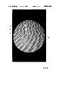
- FIG. 11 is a copy of a flood image obtained by subjecting the source of FIG. 9 to complex motion according to the present invention.
- FIG. 12 is a copy of a computer-produced representation of the complex motion of a point on the source support of the apparatus of FIG. 3.
- FIG. 13 is a schematic view of a motor-shaft combination for providing circular motion for the apparatus of FIG. 3.
- FIG. 1 illustrates a typical commercially available prior art nuclear imaging device, a gamma camera 1, having a collimator 2 through which gamma radiation from a source 8 passes to a scintillation crystal 3, through a light pipe 4 to photo multiplier tubes 5 from which signals go to an electronics section 6 for position and energy analysis resulting in output signals 7.
- FIG. 2 illustrates the gamma camera 1 disposed above a human patient 9 who has received a radiation emitting radioisotope.
- FIGS. 3-7 illustrate an apparatus 10 according to the present invention for moving a standard commercially available flood source 20 beneath a gamma camera 56.
- the apparatus 10 includes a cart 11 formed of various support members 12 welded together with a cart bottom shelf 13 extending between the support members and a cart top shelf 14 extending between the support members above the bottom shelf 13.
- the cart is mounted on wheels 15 and has a cart handle 24 extending between two of the support members above the top shelf 14.
- An electric motor 16 is mounted to a motor mount 55 which is secured to the bottom shelf 13.
- the motor used was a model no. 544 from Bodine Electric Company.
- a speed control 17 is mounted to and beneath top shelf 14 with a power cord 22 extending therefrom.
- a power cord 23 extends from the speed control to the motor 16.
- a plurality (four) of support rods 19 extend through and are secured to the top shelf 14 and the bottom shelf 13.
- a ball bearing 21 is mounted at the top of each support rod 19 and a source support plate 18 is movably disposed on the ball bearings 21.
- casters (not shown) work as well as, but more quietly than, the ball bearings.
- gear-shaft assembly 30 Between the motor 16 and the source support plate 18 is a gear-shaft assembly 30 which is shown in detail in FIG. 6. As shown in FIG. 7 the motor 16 has a gear box 25 from which a motor shaft 26 extends. A small sprocket 27 is secured to the shaft 26. A chain wraps around the small sprocket 27 and around a large sprocket 28 which is secured to a bottom shaft 31 of the gear-shaft assembly 30.
- the driven movement of the gear-shaft assembly 30 produces a complex motion pattern for the source 20 beneath the gamma camera 56. It is within the scope of this invention to move the source along a simple curve or along a complex curve. Circular motion can be achieved by simply driving a top shaft 33 by the motor directly.
- the bottom shaft 31 is disposed in and through and is rotatable within a bearing 38 which is secured to the top shelf 14.
- the shaft 31 is also disposed in and through and is rotatable within a bottom shaft gear 34.
- a bottom steel cuff 45 is secured to the bottom shaft 31 by a lock screw 41 in a recess 57 in the bottom steel cuff 45, the lock screw 41 engaging the bottom shaft 31.
- a middle shaft 32 has a first middle shaft gear secured to it by a lock screw 40.
- the first middle shaft gear mates with and turns with the bottom shaft gear 34.
- the middle shaft 32 extends through and is rotatable within a bearing 47, the bottom steel cuff 45, and a bearing 48.
- a lock collar 50 secured to the middle shaft 32 by a lock screw 44 maintains the bearings 47, 48, a gear 36, and the cuff 45 in position about the middle shaft 32.
- the middle shaft 32 extends into and is secured to a top steel cuff 46 by a lock screw 41.
- a second middle shaft gear 36 is secured to and partially within the bottom steel cuff by a lock screw 42.
- the bearing 48 extends through and is rotatable within the second middle shaft gear 36.
- a top shaft 33 extends through and is rotatable within bearings 49.
- the bearings 49 are partially disposed within the top steel cuff 46 which itself is tightly embraced about the bearings 49.
- a top shaft gear 37 secured to the top shaft 33 by a lock screw 43 mates with and turns with the second middle shaft gear 36.
- a lock collar 51 secured to the top shaft 33 by a lock screw 43 mates with and turns with the second middle shaft gear 36.
- a lock collar 51 secured to the top shaft 33 maintains the bearings 49 and the top steel cuff 46 in position above the top shaft gear 37.
- a top lock collar 52 is secured to the top shaft 33 by lock screws 44.
- a flange 53 welded to the top stop collar 52 supports and is secured to the source support plate 18 (see FIG. 5).
- the bottom shaft 31 is driven by the sprocket 28 and rotates at a fixed axis with respect to the top shelf 14.
- the middle shaft 32 driven by the bottom shaft gear 34 through the first middle shaft gear 35, moves in a circle around the bottom shaft 31.
- the gears 34, 35 control the speed of the middle shaft 32.
- the middle shaft 32 pulls the second middle shaft gear 36 along with it when it moves.
- the top steel cuff 46 moves with the middle shaft 32 since it is secured to the shaft.
- the top steel cuff 46 moves, it pulls the top shaft 33 with it.
- the top shaft gear 37 moves with the top shaft 33 and, in so doing, the top shaft gear 37 drives the second middle shaft gear 36.
- the speed of the top shaft 33 is dependent upon the gear ratio of gear 37 to gear 36 (in combination with the gear ratio of bottom shaft gear 34 to first middle shaft gear 35).
- the speed of the middle shaft 32 is dependent on the gear ratio of the bottom shaft gear 34 to the first middle shaft gear 35.
- gear ratio of gears 37, 36 was 3:1 and that of gears 34, 35 was 1.6:2.5.
- the chain 29 had a 1/4 inch pitch; the small sprocket 27 had an effective diameter of 0.996 inches; and the large sprocket 28 had an effective diameter of 4.777 inches.
- the shaft 26 had a maximum speed of 72 revolutions per minute, but it was preferred to run it at about one-half that speed. Best results were obtained when the bottom shaft 31 was initially aligned with the top shaft 33 in order to align the source support plate beneath the nuclear imaging device.
- a change in the source support plate's motion path [to effect motion of the source along other simple or complex curves in a plane illustrated by line A--A in FIG. 3 which is parallel to a plane in which individual sensors (not shown) of the gamma camera are disposed (such as the plane of line B--B in FIG. 3] can be effected by a variety of changes including, but not limited to, changes in shaft diameter, gear diameter, gear ratios, and cuff size.
- a pencil trace 54 reproduced in FIG. 8 was obtained by placing a piece of paper on the source support plate 18 and holding a pencil above and in contact with the paper while the plate was moved by the apparatus 10.
- the trace of FIG. 8 shows the path that one detector in the camera takes over the source, i.e., it indicates the areas on the source detected by one detector in the camera.
- a motion trace 68 shown in FIG. 12 was produced by a computer simulation of the motion of the apparatus 10 and represents the path followed by a point on the support plate 18 about three inches outward from the top shaft 33. (Of course, the actual path is smooth and continuous.) This trace is that which would be produced on a piece of photographic film above the source if a point light source was placed on the source support plate and then the plate was moved by the apparatus 10.
- FIGS. 9-11 demonstrate the use of the present invention's methods and apparatus when a standard source has additional small radioactive areas.
- FIG. 9 illustrates a gamma radiation source image 60 which includes hot spots or flaws 61, 62, 63 created by the addition of three cobalt-57 discs to the standard source.
- FIG. 10 shows a gamma radiation source image achieved by subjecting the source which produced image 60 to simple circular motion according to this invention. This produced a more uniform image, but also produced undesirable ring disc image tracks 64, 65, 66. Subjecting the source which produced image 60 to complex motion with the apparatus 10 achieved the relatively more uniform image 67 shown in FIG. 11. Simple circular motion of the source support plate 18 can be achieved by simply mounting a shaft beneath the source support plate and rotating it either by hand or with a motor.
- the motor 16 can have its drive shaft 26 connected directly to the support plate 18 to produce circular motion of a source placed on the support plate.
- Non-uniformity was quantitated by autoradiography. Autoradiography was performed by attaching a cardboard cassette loaded with high resolution radiographic film to a fixed surface. For ST and RE determinations, the sources were placed beneath the loaded cassette for 60 and 18 hours, respectively. For CI and CX, the sources were moved beneath the loaded cassette for 60 hours. Exposed films were then developed.
- the developed film was divided into one centimeter squares.
- a microdensitometer was used to measure the optical density of each square within the central (75%) field of view (CFOV) of each flood image. Multiple readings of arbitrary squares were taken to establish a reliability value.
- Optical density matrices were thus compiled for each flood. After appropriate smoothing according to NEMA procedures, the nonuniformity of each matrix was computed using the usual formula: the difference between the maximum and minimum smoothed pixel density divided by their sum. The standard deviation for optical densities measured in each square was also computed for each CFOV.
- each approach (ST, CI, CX and RE) was used to acquire 30,000,000 counts into a 64 by 64 digital matrix.
- the sources were imaged through a slightly defective low energy all purpose collimator to simulate the environment often encountered clinically.
- Each matrix was then analyzed using commercially available quality assurance software to compute differential and integral non-uniformity by standard methods.
- Moving the flood source improves the effective nonuniformity of the flood images using both autoradiography and standard, semiautomatic methods. This improvement persisted even in the face of nonuniformities imposed by the imaging system, accentuated by a defective collimator. The improvement was quite tolerant of severe local flaws although, in that case, complex motion was markedly better than simple circular motion. Simple circular motion resulted in unacceptable ring artifacts.
Abstract
Description
              TABLE I
______________________________________
NONUNIFORMITY OF FLOOD SOURCES BY
AUTORADIOGRAPHY NONUNIFORMITY
______________________________________
Refillable Tc-99m    3.7%
Standard Co-57       4.3%
Co-57 with circular motion
                     3.0%
Co-57 with complex motion
                     3.3%
______________________________________
              TABLE II
______________________________________
NONUNIFORMITY OF FLOODS AS DETERMINED BY
SCINTIGRAPHY
              DIFFERENTIAL
                          INTEGRAL
              NONUNI-     NONUNI-
              FORMITY     FORMITY
______________________________________
Point source    2.6%          3.4%
Refillable Tc-99m
                3.4%          5.7%
Co-57 without motion
                4.2%          6.4%
Co-57 with circular motion
                3.5%          5.4%
Co-57 with complex motion
                3.2%          5.5%
______________________________________
Claims (16)
Priority Applications (5)
| Application Number | Priority Date | Filing Date | Title |
|---|---|---|---|
| US07/160,839 US4882494A (en) | 1988-02-26 | 1988-02-26 | Apparatus and method for flooding a nuclear imaging device with radiation from an imaging source |
| PCT/GB1988/000427 WO1989008268A1 (en) | 1988-02-26 | 1988-05-31 | Apparatus and method for flooding a nuclear imaging device with radiation from an imaging source |
| AU17939/88A AU1793988A (en) | 1988-02-26 | 1988-05-31 | Apparatus and method for flooding a nuclear imaging device with radiation from an imaging source |
| EP88904592A EP0441772A1 (en) | 1988-02-26 | 1988-05-31 | Apparatus and method for flooding a nuclear imaging device with radiation from an imaging source |
| IL88922A IL88922A0 (en) | 1988-02-26 | 1989-01-10 | Apparatus and method for flooding a nuclear imaging device with radiation from an imaging source |
Applications Claiming Priority (1)
| Application Number | Priority Date | Filing Date | Title |
|---|---|---|---|
| US07/160,839 US4882494A (en) | 1988-02-26 | 1988-02-26 | Apparatus and method for flooding a nuclear imaging device with radiation from an imaging source |
Publications (1)
| Publication Number | Publication Date |
|---|---|
| US4882494A true US4882494A (en) | 1989-11-21 |
Family
ID=22578678
Family Applications (1)
| Application Number | Title | Priority Date | Filing Date |
|---|---|---|---|
| US07/160,839 Expired - Fee Related US4882494A (en) | 1988-02-26 | 1988-02-26 | Apparatus and method for flooding a nuclear imaging device with radiation from an imaging source |
Country Status (5)
| Country | Link |
|---|---|
| US (1) | US4882494A (en) |
| EP (1) | EP0441772A1 (en) |
| AU (1) | AU1793988A (en) |
| IL (1) | IL88922A0 (en) |
| WO (1) | WO1989008268A1 (en) |
Cited By (17)
| Publication number | Priority date | Publication date | Assignee | Title |
|---|---|---|---|---|
| EP0412734A2 (en) * | 1989-08-04 | 1991-02-13 | Kabushiki Kaisha Toshiba | Single photon emission CT apparatus |
| DE4009854C1 (en) * | 1990-03-24 | 1991-08-29 | Kurt Prof. Dipl.-Ing. 3004 Isernhagen De Jordan | Appts. for controlling and correcting a gamma-camera - includes container filled with liq. and radionuclides, with base adjusting mechanism |
| WO1995023348A1 (en) * | 1994-02-25 | 1995-08-31 | Massachusetts Institute Of Technology | Methods and apparatus for detecting and imaging particles |
| US6489617B1 (en) | 1999-10-18 | 2002-12-03 | Battelle Memorial Institute | Quality assurance flood source and method of making |
| US20040119030A1 (en) * | 2001-06-12 | 2004-06-24 | North American Scientific, Inc. | Thin radiation source and method of making the same |
| WO2004109332A1 (en) * | 2003-06-04 | 2004-12-16 | Hammersmith Imanet Ltd | Generating detector efficiency estimates for a oet scanner |
| US20060004277A1 (en) * | 2004-07-01 | 2006-01-05 | Greathouse William G | Initiation of dynamic data acquisition |
| US20060074306A1 (en) * | 2004-09-30 | 2006-04-06 | Gvi Technology Partners, Ltd. | Automated processing of dynamic cardiac acquisition data |
| US20060081065A1 (en) * | 2004-10-04 | 2006-04-20 | Gvi Technology Partners, Ltd. | Sensor interconnect system |
| US20080087828A1 (en) * | 2006-10-16 | 2008-04-17 | Gvi Medical Devices | Collimator for radiation detectors and method of use |
| US20090268953A1 (en) * | 2008-04-24 | 2009-10-29 | Apteryx, Inc. | Method for the automatic adjustment of image parameter settings in an imaging system |
| US20090268876A1 (en) * | 2008-04-24 | 2009-10-29 | Crucs Holdings, Llc | Methods of assessing performance in an imaging system |
| US7638760B1 (en) | 2004-05-28 | 2009-12-29 | Gvi Technology Partners, Ltd. | Method for tracking and correcting the baseline of a radiation detector |
| US20110066026A1 (en) * | 2009-04-21 | 2011-03-17 | The Regents Of The University Of California | Rf coil for use in magnetic resonance imaging in integrated spect and mr imaging |
| US20110220783A1 (en) * | 2010-03-09 | 2011-09-15 | Leonid Tsukerman | Methods and systems for calibrating a nuclear medicine imaging system |
| US9579073B2 (en) | 2010-05-07 | 2017-02-28 | Apteryx, Inc. | System and method for dentition specific image enhancement |
| US9739894B2 (en) * | 2014-06-06 | 2017-08-22 | Siemens Medical Solutions Usa, Inc. | Gamma camera dead time compensation using a companion radioisotope |
Citations (20)
| Publication number | Priority date | Publication date | Assignee | Title |
|---|---|---|---|---|
| US1531620A (en) * | 1922-06-05 | 1925-03-31 | William H Meyer | Penetrometer for x rays |
| US1589833A (en) * | 1923-12-21 | 1926-06-22 | Behnken Hermann | Measuring device for the examination of electromagnetic waves |
| US2258593A (en) * | 1940-03-18 | 1941-10-14 | Lawrence F Black | Method of calibrating roentgenographic machines |
| US2374280A (en) * | 1943-03-11 | 1945-04-24 | Walter L Gerke | X-ray timer tester |
| US3715588A (en) * | 1970-10-26 | 1973-02-06 | Norland Corp | Bone mineral analyzer |
| US4014109A (en) * | 1975-02-12 | 1977-03-29 | Anasim, Inc. | Test apparatus for nuclear imaging devices |
| US4066902A (en) * | 1974-03-23 | 1978-01-03 | Emi Limited | Radiography with detector compensating means |
| US4071760A (en) * | 1974-01-31 | 1978-01-31 | Emi Limited | Radiography apparatus with photocell drift compensating means |
| US4172978A (en) * | 1976-08-17 | 1979-10-30 | Emi Limited | Radiography |
| US4321471A (en) * | 1980-02-04 | 1982-03-23 | The Machlett Laboratories, Inc. | X-Ray target monitor |
| US4331869A (en) * | 1980-06-23 | 1982-05-25 | Capintec, Inc. | Dynamic cardiac quality assurance phantom system and method |
| US4506375A (en) * | 1983-09-27 | 1985-03-19 | Manson James E | X-Ray calibration system |
| US4516025A (en) * | 1980-09-26 | 1985-05-07 | Tokyo Shibaura Denki Kabushiki Kaisha | Method and apparatus for controlling scintillation camera |
| US4517460A (en) * | 1981-06-24 | 1985-05-14 | U.S. Philips Corporation | Method of calibrating a gamma camera, and a gamma camera including a calibration device |
| US4571491A (en) * | 1983-12-29 | 1986-02-18 | Shell Oil Company | Method of imaging the atomic number of a sample |
| US4613754A (en) * | 1983-12-29 | 1986-09-23 | Shell Oil Company | Tomographic calibration apparatus |
| US4646341A (en) * | 1985-03-28 | 1987-02-24 | Upa Technology, Inc. | Calibration standard for X-ray fluorescence thickness |
| US4649561A (en) * | 1983-11-28 | 1987-03-10 | Ben Arnold | Test phantom and method of use of same |
| US4663772A (en) * | 1985-09-30 | 1987-05-05 | Picker International, Inc. | Bone mineral analysis phantom |
| US4697075A (en) * | 1986-04-11 | 1987-09-29 | General Electric Company | X-ray imaging system calibration using projection means |
-
1988
- 1988-02-26 US US07/160,839 patent/US4882494A/en not_active Expired - Fee Related
- 1988-05-31 EP EP88904592A patent/EP0441772A1/en not_active Withdrawn
- 1988-05-31 WO PCT/GB1988/000427 patent/WO1989008268A1/en not_active Application Discontinuation
- 1988-05-31 AU AU17939/88A patent/AU1793988A/en not_active Abandoned
-
1989
- 1989-01-10 IL IL88922A patent/IL88922A0/en unknown
Patent Citations (20)
| Publication number | Priority date | Publication date | Assignee | Title |
|---|---|---|---|---|
| US1531620A (en) * | 1922-06-05 | 1925-03-31 | William H Meyer | Penetrometer for x rays |
| US1589833A (en) * | 1923-12-21 | 1926-06-22 | Behnken Hermann | Measuring device for the examination of electromagnetic waves |
| US2258593A (en) * | 1940-03-18 | 1941-10-14 | Lawrence F Black | Method of calibrating roentgenographic machines |
| US2374280A (en) * | 1943-03-11 | 1945-04-24 | Walter L Gerke | X-ray timer tester |
| US3715588A (en) * | 1970-10-26 | 1973-02-06 | Norland Corp | Bone mineral analyzer |
| US4071760A (en) * | 1974-01-31 | 1978-01-31 | Emi Limited | Radiography apparatus with photocell drift compensating means |
| US4066902A (en) * | 1974-03-23 | 1978-01-03 | Emi Limited | Radiography with detector compensating means |
| US4014109A (en) * | 1975-02-12 | 1977-03-29 | Anasim, Inc. | Test apparatus for nuclear imaging devices |
| US4172978A (en) * | 1976-08-17 | 1979-10-30 | Emi Limited | Radiography |
| US4321471A (en) * | 1980-02-04 | 1982-03-23 | The Machlett Laboratories, Inc. | X-Ray target monitor |
| US4331869A (en) * | 1980-06-23 | 1982-05-25 | Capintec, Inc. | Dynamic cardiac quality assurance phantom system and method |
| US4516025A (en) * | 1980-09-26 | 1985-05-07 | Tokyo Shibaura Denki Kabushiki Kaisha | Method and apparatus for controlling scintillation camera |
| US4517460A (en) * | 1981-06-24 | 1985-05-14 | U.S. Philips Corporation | Method of calibrating a gamma camera, and a gamma camera including a calibration device |
| US4506375A (en) * | 1983-09-27 | 1985-03-19 | Manson James E | X-Ray calibration system |
| US4649561A (en) * | 1983-11-28 | 1987-03-10 | Ben Arnold | Test phantom and method of use of same |
| US4571491A (en) * | 1983-12-29 | 1986-02-18 | Shell Oil Company | Method of imaging the atomic number of a sample |
| US4613754A (en) * | 1983-12-29 | 1986-09-23 | Shell Oil Company | Tomographic calibration apparatus |
| US4646341A (en) * | 1985-03-28 | 1987-02-24 | Upa Technology, Inc. | Calibration standard for X-ray fluorescence thickness |
| US4663772A (en) * | 1985-09-30 | 1987-05-05 | Picker International, Inc. | Bone mineral analysis phantom |
| US4697075A (en) * | 1986-04-11 | 1987-09-29 | General Electric Company | X-ray imaging system calibration using projection means |
Non-Patent Citations (7)
| Title |
|---|
| NEMA A Guide to Revised Standards for Performance Measurements of Scintillation Cameras, National Electrical Manufactures Association, 1986. * |
| Perspectives on Tomography, Keyes, The Journal of Nuclear Medicine, vol. 23, No. 7, 1982. * |
| Physical Attributes of Single Photon Tomography, Budinger, The Journal of Nuclear Medicine, vol. 21, No. 6, 1980. * |
| Physical Attributes of Single-Photon Tomography, Budinger, The Journal of Nuclear Medicine, vol. 21, No. 6, 1980. |
| Single Photon Emission Computed Tomography (SPECT) Principles and Instrumentation, Jaszczak and Coleman, Investigative Radiology, Dec. 1985. * |
| Uniformity Correction for SPECT Using a Mapped Cobalt 57 Sheet Source, Oppenheim and Appledorn, The Journal of Nuclear Medicine, vol. 26, No. 4, Apr. 1985. * |
| Uniformity Correction for SPECT Using a Mapped Cobalt-57 Sheet Source, Oppenheim and Appledorn, The Journal of Nuclear Medicine, vol. 26, No. 4, Apr. 1985. |
Cited By (28)
| Publication number | Priority date | Publication date | Assignee | Title |
|---|---|---|---|---|
| EP0412734A2 (en) * | 1989-08-04 | 1991-02-13 | Kabushiki Kaisha Toshiba | Single photon emission CT apparatus |
| US5055687A (en) * | 1989-08-04 | 1991-10-08 | Kabushiki Kaisha Toshiba | Single photon emission ct apparatus |
| EP0412734A3 (en) * | 1989-08-04 | 1993-01-07 | Kabushiki Kaisha Toshiba | Single photon emission ct apparatus |
| DE4009854C1 (en) * | 1990-03-24 | 1991-08-29 | Kurt Prof. Dipl.-Ing. 3004 Isernhagen De Jordan | Appts. for controlling and correcting a gamma-camera - includes container filled with liq. and radionuclides, with base adjusting mechanism |
| WO1995023348A1 (en) * | 1994-02-25 | 1995-08-31 | Massachusetts Institute Of Technology | Methods and apparatus for detecting and imaging particles |
| US6489617B1 (en) | 1999-10-18 | 2002-12-03 | Battelle Memorial Institute | Quality assurance flood source and method of making |
| US20040119030A1 (en) * | 2001-06-12 | 2004-06-24 | North American Scientific, Inc. | Thin radiation source and method of making the same |
| US6787786B2 (en) | 2001-06-12 | 2004-09-07 | North American Scientific, Inc. | Thin radiation source and method of making the same |
| WO2004109332A1 (en) * | 2003-06-04 | 2004-12-16 | Hammersmith Imanet Ltd | Generating detector efficiency estimates for a oet scanner |
| US20060249682A1 (en) * | 2003-06-04 | 2006-11-09 | Darren Hogg | Generating detector efficiency estimates for a pet scanner |
| US7564035B2 (en) | 2003-06-04 | 2009-07-21 | Hammersmith Imanet Limited | Generating detector efficiency estimates for a pet scanner |
| US7638760B1 (en) | 2004-05-28 | 2009-12-29 | Gvi Technology Partners, Ltd. | Method for tracking and correcting the baseline of a radiation detector |
| US20060004277A1 (en) * | 2004-07-01 | 2006-01-05 | Greathouse William G | Initiation of dynamic data acquisition |
| US8014850B2 (en) | 2004-07-01 | 2011-09-06 | Gvi Technology Partners, Ltd. | Initiation of dynamic data acquisition |
| US7502500B2 (en) | 2004-09-30 | 2009-03-10 | Gvi Technology Partners, Ltd. | Automated processing of dynamic cardiac acquisition data |
| US20060074306A1 (en) * | 2004-09-30 | 2006-04-06 | Gvi Technology Partners, Ltd. | Automated processing of dynamic cardiac acquisition data |
| US20060081065A1 (en) * | 2004-10-04 | 2006-04-20 | Gvi Technology Partners, Ltd. | Sensor interconnect system |
| US8231414B2 (en) | 2004-10-04 | 2012-07-31 | Gvi Technology Partners, Ltd. | Sensor interconnect system |
| US7612343B2 (en) | 2006-10-16 | 2009-11-03 | Gvi Medical Devices | Collimator for radiation detectors and method of use |
| US20080087828A1 (en) * | 2006-10-16 | 2008-04-17 | Gvi Medical Devices | Collimator for radiation detectors and method of use |
| US7775714B2 (en) | 2008-04-24 | 2010-08-17 | Crucs Holdings, Llc | Methods of assessing performance in an imaging system |
| US20090268876A1 (en) * | 2008-04-24 | 2009-10-29 | Crucs Holdings, Llc | Methods of assessing performance in an imaging system |
| US20090268953A1 (en) * | 2008-04-24 | 2009-10-29 | Apteryx, Inc. | Method for the automatic adjustment of image parameter settings in an imaging system |
| US20110066026A1 (en) * | 2009-04-21 | 2011-03-17 | The Regents Of The University Of California | Rf coil for use in magnetic resonance imaging in integrated spect and mr imaging |
| US20110220783A1 (en) * | 2010-03-09 | 2011-09-15 | Leonid Tsukerman | Methods and systems for calibrating a nuclear medicine imaging system |
| US8415632B2 (en) * | 2010-03-09 | 2013-04-09 | General Electric Company | Methods and systems for calibrating a nuclear medicine imaging system |
| US9579073B2 (en) | 2010-05-07 | 2017-02-28 | Apteryx, Inc. | System and method for dentition specific image enhancement |
| US9739894B2 (en) * | 2014-06-06 | 2017-08-22 | Siemens Medical Solutions Usa, Inc. | Gamma camera dead time compensation using a companion radioisotope |
Also Published As
| Publication number | Publication date |
|---|---|
| EP0441772A1 (en) | 1991-08-21 |
| IL88922A0 (en) | 1989-08-15 |
| AU1793988A (en) | 1989-09-22 |
| WO1989008268A1 (en) | 1989-09-08 |
Similar Documents
| Publication | Publication Date | Title |
|---|---|---|
| US4882494A (en) | Apparatus and method for flooding a nuclear imaging device with radiation from an imaging source | |
| Zanzonico | Routine quality control of clinical nuclear medicine instrumentation: a brief review | |
| Kennedy et al. | 3D iteratively reconstructed spatial resolution map and sensitivity characterization of a dedicated cardiac SPECT camera | |
| US20090084947A1 (en) | Method for calibrating nuclear medicine diagnosis apparatus | |
| JP2000028730A (en) | Gamma-ray camera | |
| JP5719163B2 (en) | Calibration source for calibrating nuclear medicine imaging systems | |
| US4138611A (en) | Fan beam CT apparatus with post-processing weighting of picture element signals | |
| US5959300A (en) | Attenuation correction in a medical imaging system using computed path lengths and attenuation values of a model attenuation medium | |
| Salvado et al. | Development of a practical calibration procedure for a clinical SPECT/MRI system using a single INSERT prototype detector and multimini slit-slat collimator | |
| US8415632B2 (en) | Methods and systems for calibrating a nuclear medicine imaging system | |
| Saha et al. | Performance characteristics of PET scanners | |
| US3431413A (en) | Rotational technique for assessing quantity and distribution of body radioactivity | |
| Siegel et al. | Rotating scintillation camera SPECT acceptance testing and quality control | |
| Nichols et al. | Instrumentation quality assurance and performance | |
| JPH0244730Y2 (en) | ||
| Nichols et al. | Instrumentation quality assurance and performance | |
| Hines et al. | National Electrical Manufacturers Association recommendations for implementing SPECT instrumentation quality control | |
| EP4278975A1 (en) | Imaging system for detecting x-ray and gamma radiation | |
| Ahluwalia | Single-Photon Emission Computed Tomography (SPECT) Imaging System and Quality Control | |
| Jacobson et al. | Evaluation of an SS White Panorex x-ray machine | |
| O’Connor | Quality control of scintillation cameras (Planar and SPECT) | |
| Poli et al. | Quality Control of Planar and SPECT Imaging Systems | |
| Strand et al. | The dual photopeak-area method applied to scintillation camera measurements of effective depth and activity of in vivo 123 I-distributions | |
| JPS586499A (en) | Ray source for correcting positron ct device | |
| Work | Guidelines on Quality Control for Nuclear Medicine Instrumentation |
Legal Events
| Date | Code | Title | Description |
|---|---|---|---|
| AS | Assignment |
Owner name: DUNCAN, MICHAEL D., 4315 WEST LOVERS LANE, DALLAS, Free format text: ASSIGNMENT OF ASSIGNORS INTEREST.;ASSIGNOR:SIMON, THEODORE;REEL/FRAME:004940/0746 Effective date: 19880223 Owner name: DUNCAN, MICHAEL D., 4315 WEST LOVERS LANE, DALLAS, Free format text: ASSIGNMENT OF ASSIGNORS INTEREST.;ASSIGNOR:ROGERS, ROXANNE R.;REEL/FRAME:004940/0749 Effective date: 19880308 Owner name: DUNCAN, MICHAEL D., 4315 WEST LOVERS LANE, DALLAS, Free format text: ASSIGNMENT OF ASSIGNORS INTEREST.;ASSIGNOR:KIRBY, STEVEN B.;REEL/FRAME:004940/0752 Effective date: 19880223 Owner name: DUNCAN, MICHAEL D., 4315 WEST LOVERS LANE, DALLAS, Free format text: ASSIGNMENT OF ASSIGNORS INTEREST.;ASSIGNOR:MATTHIESEN, SHARON;REEL/FRAME:004940/0755 Effective date: 19880223 Owner name: DUNCAN, MICHAEL D.,TEXAS Free format text: ASSIGNMENT OF ASSIGNORS INTEREST;ASSIGNOR:SIMON, THEODORE;REEL/FRAME:004940/0746 Effective date: 19880223 Owner name: DUNCAN, MICHAEL D.,TEXAS Free format text: ASSIGNMENT OF ASSIGNORS INTEREST;ASSIGNOR:ROGERS, ROXANNE R.;REEL/FRAME:004940/0749 Effective date: 19880308 Owner name: DUNCAN, MICHAEL D.,TEXAS Free format text: ASSIGNMENT OF ASSIGNORS INTEREST;ASSIGNOR:KIRBY, STEVEN B.;REEL/FRAME:004940/0752 Effective date: 19880223 Owner name: DUNCAN, MICHAEL D.,TEXAS Free format text: ASSIGNMENT OF ASSIGNORS INTEREST;ASSIGNOR:MATTHIESEN, SHARON;REEL/FRAME:004940/0755 Effective date: 19880223 |
|
| REMI | Maintenance fee reminder mailed | ||
| LAPS | Lapse for failure to pay maintenance fees | ||
| FP | Lapsed due to failure to pay maintenance fee |
Effective date: 19930912 |
|
| STCH | Information on status: patent discontinuation |
Free format text: PATENT EXPIRED DUE TO NONPAYMENT OF MAINTENANCE FEES UNDER 37 CFR 1.362 |