US4876653A - Programmable multiple blender - Google Patents
Programmable multiple blender Download PDFInfo
- Publication number
- US4876653A US4876653A US07/073,974 US7397487A US4876653A US 4876653 A US4876653 A US 4876653A US 7397487 A US7397487 A US 7397487A US 4876653 A US4876653 A US 4876653A
- Authority
- US
- United States
- Prior art keywords
- flow
- blend
- products
- product
- ratio
- Prior art date
- Legal status (The legal status is an assumption and is not a legal conclusion. Google has not performed a legal analysis and makes no representation as to the accuracy of the status listed.)
- Expired - Lifetime
Links
Images


Classifications
-
- B—PERFORMING OPERATIONS; TRANSPORTING
- B67—OPENING, CLOSING OR CLEANING BOTTLES, JARS OR SIMILAR CONTAINERS; LIQUID HANDLING
- B67D—DISPENSING, DELIVERING OR TRANSFERRING LIQUIDS, NOT OTHERWISE PROVIDED FOR
- B67D7/00—Apparatus or devices for transferring liquids from bulk storage containers or reservoirs into vehicles or into portable containers, e.g. for retail sale purposes
- B67D7/06—Details or accessories
- B67D7/74—Devices for mixing two or more different liquids to be transferred
- B67D7/743—Devices for mixing two or more different liquids to be transferred electrically or electro-mechanically operated
- B67D7/744—Devices for mixing two or more different liquids to be transferred electrically or electro-mechanically operated involving digital counting
-
- G—PHYSICS
- G05—CONTROLLING; REGULATING
- G05D—SYSTEMS FOR CONTROLLING OR REGULATING NON-ELECTRIC VARIABLES
- G05D11/00—Control of flow ratio
- G05D11/02—Controlling ratio of two or more flows of fluid or fluent material
- G05D11/13—Controlling ratio of two or more flows of fluid or fluent material characterised by the use of electric means
- G05D11/131—Controlling ratio of two or more flows of fluid or fluent material characterised by the use of electric means by measuring the values related to the quantity of the individual components
- G05D11/132—Controlling ratio of two or more flows of fluid or fluent material characterised by the use of electric means by measuring the values related to the quantity of the individual components by controlling the flow of the individual components
-
- B—PERFORMING OPERATIONS; TRANSPORTING
- B67—OPENING, CLOSING OR CLEANING BOTTLES, JARS OR SIMILAR CONTAINERS; LIQUID HANDLING
- B67D—DISPENSING, DELIVERING OR TRANSFERRING LIQUIDS, NOT OTHERWISE PROVIDED FOR
- B67D7/00—Apparatus or devices for transferring liquids from bulk storage containers or reservoirs into vehicles or into portable containers, e.g. for retail sale purposes
- B67D7/06—Details or accessories
- B67D7/74—Devices for mixing two or more different liquids to be transferred
- B67D2007/745—Devices for mixing two or more different liquids to be transferred for obtaining fuel of a given octane level
- B67D2007/746—Devices for mixing two or more different liquids to be transferred for obtaining fuel of a given octane level by mixing different fuel grades or fuel and oil
-
- Y—GENERAL TAGGING OF NEW TECHNOLOGICAL DEVELOPMENTS; GENERAL TAGGING OF CROSS-SECTIONAL TECHNOLOGIES SPANNING OVER SEVERAL SECTIONS OF THE IPC; TECHNICAL SUBJECTS COVERED BY FORMER USPC CROSS-REFERENCE ART COLLECTIONS [XRACs] AND DIGESTS
- Y10—TECHNICAL SUBJECTS COVERED BY FORMER USPC
- Y10T—TECHNICAL SUBJECTS COVERED BY FORMER US CLASSIFICATION
- Y10T137/00—Fluid handling
- Y10T137/0318—Processes
- Y10T137/0324—With control of flow by a condition or characteristic of a fluid
- Y10T137/0329—Mixing of plural fluids of diverse characteristics or conditions
-
- Y—GENERAL TAGGING OF NEW TECHNOLOGICAL DEVELOPMENTS; GENERAL TAGGING OF CROSS-SECTIONAL TECHNOLOGIES SPANNING OVER SEVERAL SECTIONS OF THE IPC; TECHNICAL SUBJECTS COVERED BY FORMER USPC CROSS-REFERENCE ART COLLECTIONS [XRACs] AND DIGESTS
- Y10—TECHNICAL SUBJECTS COVERED BY FORMER USPC
- Y10T—TECHNICAL SUBJECTS COVERED BY FORMER US CLASSIFICATION
- Y10T137/00—Fluid handling
- Y10T137/2496—Self-proportioning or correlating systems
- Y10T137/2499—Mixture condition maintaining or sensing
-
- Y—GENERAL TAGGING OF NEW TECHNOLOGICAL DEVELOPMENTS; GENERAL TAGGING OF CROSS-SECTIONAL TECHNOLOGIES SPANNING OVER SEVERAL SECTIONS OF THE IPC; TECHNICAL SUBJECTS COVERED BY FORMER USPC CROSS-REFERENCE ART COLLECTIONS [XRACs] AND DIGESTS
- Y10—TECHNICAL SUBJECTS COVERED BY FORMER USPC
- Y10T—TECHNICAL SUBJECTS COVERED BY FORMER US CLASSIFICATION
- Y10T137/00—Fluid handling
- Y10T137/2496—Self-proportioning or correlating systems
- Y10T137/2514—Self-proportioning flow systems
- Y10T137/2521—Flow comparison or differential response
- Y10T137/2529—With electrical controller
Definitions
- the field of the present invention relates generally to dispensing systems for delivering a desired blend of two products to a user, and more particularly relates to such systems incorporating proportional flow control valves controlled by a closed loop system including a microprocessor programmed to effect control of the valves for delivering the desired blend of the two products.
- Buchanan U.S. Pat. No. 3,895,738 discloses a blending system for blending two products together in order to obtain a desired product for dispensing.
- Buchanan individually sets the rates of flow of each one of the two products for accomplishing the required blending. No feedback or closed loop operation is evident in Buchanan.
- Kierbow, et al U.S. Pat. No. 4,265,266 teaches the use of proportional control valves in a blending system, and uses closed loop control via a microprocesser for controlling the rate of flow of one of the two products being blending.
- the valves control hydraulic motors, which in turn control pumps for pumping the fluid.
- Crain, et al U.S. Pat. No. 4,538,222 teaches a system for producing a fracturing fluid consisting of water and number of different additives, wherein a microprocessor is programmed to respond to the total flow of water and each additive, and to preselected concentration values for each additive for controlling the speed of pumps associated with each additive to maintain a desired concentration of each additive in the mixture.
- Cox, et al U.S. Pat. No. 4,433,701 teaches a polymer mixing system including closed loop control. Cox uses a micro-processor 8 to control a gear pump 10 as a function of the error between a "processed input" and a "set point input".
- Vetter, et al U.S. Pat. No. 4,440,314 teaches the control of the "dosing of at least one fluid component of a mixture of fluids. Vetter uses closed loop control in order to maintain mixing accuracy. The flow rates of two components that are to be mixed are compared for controlling the flow rate of one of these components in order to maintain a desired mixture".
- Koni, et al U.S. Pat. No. 4,345,612 teaches closed loop control for mixing two gases together in a desired ratio.
- the flow rates of each one of the gases are measured using a pair of flow rate sensors, respectively, in combination with a microprocessor controller for controlling the valves associated with each one of the gases.
- U.S. Pat. No. 4,083,473 discloses a system for blending that provides either a low octane fuel, a high octane fuel, or an intermediate octane fuel that is a blend of the latter two.
- the system includes flow meters for providing signals indicative of the rate of flow of the low octane and high octane fuels, respectively.
- a control unit is responsive to the signals for adjusting a blend control valve in closed loop fashion to provide a desired blend of the low and high octane fuels.
- Lombard U.S. Pat. No. 4,043,300 discloses an apparatus and circuitry for comparing the flow rates of two fluids, such as air and fuel being delivered to an engine, for controlling a valve setting the flow rate of one of the fluids, in order to maintain a desired ratio of mixing of the fluids.
- Gulbrandsen U.S. Pat. No. 3,717,283 discloses a gasoline blending apparatus including electrical circuitry and electromagnetic valving means for delivering either premium fuel, low octane fuel, or a blend of the two to a nozzle.
- the system disclosed does not include closed loop control, and is believed to teach the opening and closing of valves to deliver either one of the three selectable octane fuels, wherein the valves are either closed or open to a predetermined opening for the orifice of the valve.
- An object of the present invention is to provide an improved blending system for a liquid product dispensing system.
- Another object of the invention is to provide a dispensing system including a blending subsystem providing for the blending of two products into any number of programmed blends, with each blend being some desired ratio of the two products, typically ranging from 1:99 or 99:1, for example.
- Still another object of the invention is to provide an improved blending system capable of dispensing multiple blends from a single nozzle.
- Another object of the invention is to provide in a blending system the capability of varying the product flow rates of each one of two products individually in proportion to given respective electrical input signals.
- Another object of the invention is to provide an improved microprocessor controlled blending system for blending two products into a product representative of some desired ratio of the products from a range of available ratios.
- Yet another object of the invention is to provide a system for blending two products together into a desired ratio, via the modulation in real time of the flow control valves associated with each one of the products.
- Another object of the invention is to minimize contamination of the blended product by insuring the blending together of the two products upstream from a nozzle.
- Yet another object of the invention is to provide in a dispensing system the capability for controlling the ultimate product flow rate while maintaining a desired blend.
- Another object of the invention is to provide in an improved blending system the capability for compensating for changes in inlet line pressure of each one of the products being blended via control of the respective valves for each product responsive to inlet line pressure, for maintaining both the desired blend and the product flow rate at predetermined programmed values.
- the present invention includes flow control valve means for controlling the flow rate of each one of two products, flow meter means for providing electrical signals indicative of the flow rate of each one of the products flowing through the flow valve control means, blender manifold means for receiving the two products after the latter flow through their respective flow control valve means, for blending the two products together for providing an ultimate product for dispensing from a nozzle connected to an output port of the blend manifold means, and control means including microprocessor means programmed to respond to both a blend select signal and the product flow rate signals from the flow rate meter means, for providing dual closed loop control of the flow control valve means in a manner to maintain a desired blend of the two products being dispensed at a desired product flow rate.
- FIG. 1 is a pictorial drawing of one embodiment of the invention
- FIG. 2 is a system block diagram of an embodiment of the invention
- FIG. 3 is a block schematic diagram of an embodiment of the invention.
- FIG. 4 is a partial cross-sectional view of a proportional flow control valve used in various embodiments of the invention.
- FIG. 5 is a block fluid control diagram showing dynamic system elements for an embodiment of the invention.
- FIG. 6 shows a block schematic diagram of a control model algorithm of an embodiment of the invention
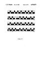
- FIG. 7 shows a tracking ratio assignment array for a 36 to 100 blend following the algorithm of one embodiment of the invention.
- FIG. 8 shows a numerator tracking ratio assignment array for the algorithm of one embodiment of the invention
- FIG. 9 is a flowchart for the main program for the hydraulics interface of one embodiment of the invention showing the connection of program modules thereof;
- FIG. 10 is a flowchart of the program module "INIT SYS" of FIG. 9;
- FIG. 11 is a flowchart of the program module "SYS STAT" of FIG. 9;
- FIG. 12 is a flowchart of the program module "LOOP CONTROL" designated in FIG. 9 as "LP CNTRL";
- FIG. 13 is a flowchart of the program module "PRESET QUERY" of FIG. 9;
- FIG. 14 is a flowchart of the program module "RATIO TRK" of FIG. 9;
- FIG. 15 is a flowchart of the program module "RATIO ERR" of FIG. 9;
- FIG. 16 is a flowchart of the program module "STARTUP" of FIG. 9;
- FIG. 17 is a flowchart of the program module "VALVE CNTRL" of FIG. 9;
- FIG. 18 is a flowchart of the program module "RESIDUAL" of FIG. 9;
- FIGS. 19 and 20 show curves illustrative of the initial ramping up and typical mid-cycle corrections, respectively, for controlling the duty cycle of the valves for a 1 to 9 blend;
- FIGS. 21A through 21H show a circuit and logic schematic diagram of the hydraulic interface board of one embodiment of the invention.
- FIG. 22 shows an interconnection diagram between the pump controller board and hydraulic interface board of one embodiment of the invention
- FIGS. 23A through 23C show a circuit and logic schematic diagram for the valve driver board of one embodiment of the invention.
- FIG. 24 shows a circuit schematic diagram of a valve power supply for one embodiment of the invention.
- one embodiment of the present invention includes a control display module 1, first and second product delivery lines 3 and 5 for delivering products under pressure from a pump (not shown) through in-line filters 7 and 9, respectively, to a first flow control valve 11 for controlling and flow rate of the first product, and to a second flow control valve 13 for controlling the rate of flow of a second product, respectively, a flow meter 15 connected in line with the flow control valve 11 for providing an electrical signal indicative of the rate of flow of the first product, a second flow meter 178 connected in line with the flow control valve 13 for providing an electrical signal indicative of the rate of flow of the second product, a pair of coupling pipes or hoses 19, 21, for connecting flow control valve 11 to flow meter 15, and flow control valve 13 to flow meter 17, respectively, a pair of delivery pipes or hoses 23 and 25 connected to the outlet ports 27, 29, respectively of flow meters 15 and 17, respectively, a pair of flexible hoses 31, 33 connected to the outlet pipes or conduits 23, 25, respectively, the other ends of the hoses 31, 33 being connected to
- control display module or panel 1 includes a blend selection section 45 providing a number of individually selectable switches 47 for selecting a desired blend of the first product (such as a low octane fuel) and a second product (such as a high octane fuel), for dispensing from the nozzle 41 typically into the gasoline tank of an automobile, for example.
- a blend selection section 45 providing a number of individually selectable switches 47 for selecting a desired blend of the first product (such as a low octane fuel) and a second product (such as a high octane fuel), for dispensing from the nozzle 41 typically into the gasoline tank of an automobile, for example.
- an electronic readout 49 for displaying the price per unit volume of the product dispensed from the nozzle 41
- an electronic display 51 for displaying the volume or quantity of the product dispensed
- another electronic display 53 for showing the price per unit volume of the product selected on the blend selection panel 45, for example.
- flow meter 15 and flow control valve 11 can be interchanged without any effect on system performance.
- flow meter 17 can be interchanged in position with flow control valve 13.
- additional valves such as check valves and on/off solenoid valves, for example.
- Electrical signals indicative of the flow rates of the first and second products are connected from the flow meters 27 and 29 via electrical cables 55 and 57, respectively, to the control/display module 1.
- Feedback control signals are carried from the control/display module 1 via electrical cables 59 and 61 to the flow control valves 11 and 13, respectively, for controlling in real time the rate of flow of the first and second products, respectively.
- Check valves (not shown) are typically included in the liquid product distribution lines, and in this example may be located either in the input ports 35 and 37 of the blend manifold 39, or elsewhere in the fluid path between the flow meters 15 and 17, and the nozzle 41, in this example.
- FIG. 2 A block diagram of the basic system of one embodiment of the invention is shown in FIG. 2.
- the illustrative system includes a main power supply 62, including a step-down AC transformer (not shown), and an internal battery and circuitry (not shown) for supplying backup power in the event of failure of the AC line voltage.
- the main power supply 62 drives a main regulator 63 that includes a switching regulator and converter system (not shown), for example, for converting AC to DC.
- the DC output voltage from the main regulator 63 is typically 14.5 volts DC and 5 volts DC for operating the various electronic subsystems of the present dispenser.
- the main regulator 63 drives a display regulator or power supply 65, typically a DC-to-DC supply for converting 13.0 volts DC to 175.0 volts DC for operating various display elements, such as those associated with the blend selection panel 45, the sales price display 49, the gallons display 51, and the price per gallon display 53.
- a display regulator or power supply 65 typically a DC-to-DC supply for converting 13.0 volts DC to 175.0 volts DC for operating various display elements, such as those associated with the blend selection panel 45, the sales price display 49, the gallons display 51, and the price per gallon display 53.
- the display power supply 65 in this example, provides power to a main front display 67, and a main rear display 69. Some of the elements of the main front display 67 have been described as illustrated in FIG. 1.
- the main rear display 69 typically consists of an identical display as shown for the control display module 1, for control of a second fuel distribution system located within the same pump housing (not shown), the duplicate system being identical to that shown in FIG. 1.
- the main displays 67, 69 are used to display the price per unit of volume, total volume dispensed, and total price for the transaction. There is 5 one main display per fueling position.
- the main display board contains circuitry to sense the temperature of the displays and to turn on the display heaters if they are below a safe operating level.
- the display boards 66, 67, 69, and 70 receive multiplexed display information from the pump controller 71.
- the front and rear boards PPU (Price Per Unit) boards 66, 70 are used to post the price of each grade of product, as received from Pump Controller board 71. There are typically two displays per grade for providing cash/credit options.
- the PPU displays 66 and 70 receive multiplexed display information from the Pump Controller board 71. This information is routed through the main display boards 67, 69.
- the Pump Controller Board 71 is a standard item manufactured and sold by Gilbarco Inc., Greensboro, N.C., under part number T15841.
- the controller board 71 is sold preprogrammed by Gilbarco.
- the Pump Controller 71 includes a Z80 microprocessor (in this example) which typically communicates with a remote "operations building"(not shown), stores information for providing control signals to a hydraulic interface subsystem 73, and also may provide the computations for pricing the fuel dispensed by the system. Also the Pump Controller 71 provides control signals for operating the various display elements of the main front display 67 and main rear display 69. It maintains grade price information, volume totals, money totals, and blend ratios in battery backed RAM on the Pump Controller Board 71.
- the controller board 71 provides multiplexed display information 5 for the main displays 67, 69 and PPU displays 66, 70, communicates with outside consoles via a communications loop (not shown), and transmits and receives data from the hydraulic interface board 73 via a parallel bus 460.
- the hydraulic interface subsystem 73 includes the logic and other electronics under control of the Pump Controller 71 for providing valve driver signals for operating a valve driver network 75 to modulate the proportional flow control valves 11 and 13, in this example, for providing the desired flow rates for the associated products to be blended.
- the hydraulic interface board 73 includes a Z80 microprocessor, and interface circuitry for the pulsers 27, 29, and pump handle 442 (described below) and a communications loop (not shown). Note that in certain instances the system operates to only permit high octane fuel to be delivered to the nozzle 41, or alternately only low octane fuel to be delivered to the nozzle 41, for example, depending upon the operation of the blend selection panel 45.
- the valve driver board 75 is supplied power directly from a valve power supply 77, the latter being driven by the AC line.
- the blend select switches 47 are used to enable the customer to select the desired grade of fuel.
- the switches 47 are polled by the Pump Controller Board 71 which senses when a switch 47 is depressed.
- the pump controller board 71 is programmable for providing a range of different blends in association with different ones of the blend select switches 47.
- the valve driver printed circuit board 75 is used to provide valve control signals for both operating valves 11, 13 and valves 79, 81 associated with another nozzle on the rear side of the pump housing (not shown), for permitting refueling of a vehicle near the rear of the housing (not shown), while simultaneously fueling a vehicle located at the front of the housing.
- low octane fuel 83 is delivered under pressure to the valves 11 and 79
- high octane fuel 85 is delivered under pressure to the valves 13 and 81.
- the control signals carried as signal lines 59 and 61 were 100 Hz pulse width modulated (PWM) signals, for example.
- each one of the valves 11, 13, 79, and 81 are proportional poppet valves as shown in FIG. 4, which is described in detail in the following paragraphs.
- Another type of proportional valve that may be of use in the present system is a proportional piston valve as described in copending application Ser. No. 064,203, filed June 18, 1987, entitled “Piston Flow Control Valve", and having a common assignee.
- the control signals applied to these valves are pulse signals, which are pulse width modulated (PWM) in order to control the opening of the associated one of valves 11, 13, 83, and 85 for obtaining a particular flow rate of the associated product.
- PWM pulse width modulated
- the proportional poppet valve 101 illustrated in this example of the invention is shown in FIG. 4.
- a proportional solenoid 103 is controlled by the PWM (pulse width modulated) control signals for extending solenoid plunger 105, from plunger tube 107 into solenoid cavity 109, to push against poppet seat 111 for moving the profiled poppet 113 downward.
- Poppet 113 is moved downward to open valve 101 a sufficient amount for obtaining a desired rate of flow of product out of discharge port 115.
- valve 101 When valve 101 is opened, fluid flows into the inlet port 119, through valve inlet cavity 121, and valve discharge channel 117 (the size of the channel is directly related to the extent of downward movement or position of the unseated poppet 113), into discharge port 115.
- a fail-shut return spring 123 urges poppet 113 upward to a closed valve or seated position, and will seat the poppet 113 in the event of a power failure, or failure of solenoid 103 (fail-shut operation).
- a discharge O-ring 125, poppet seal 127, upper O-ring 129, a rolling diaphragm 130, seal retaining ring 131, plunger tube O-ring 133, cartridge retaining flange 135, and flange bolts 137 are located as shown.
- a pressure balancing orifice 139 is provided axially through poppet 113 to equate the pressure between discharge port 115 and solenoid cavity 109.
- a "valve cartridge” subassembly 141 includes all of the components between the indicated arrows for 141, as shown.
- a valve cartridge bracket and support 143 forms part of the cartridge assembly 141, and is retained via flange 135, as shown.
- the product meters 15 and 17 are each Gilbarco Part No. PA010 manufactured by Gilbarco Inc., Greensboro, N.C.. These meters deliver pulse trains that are indicative of the rate of flow of the product through the meters 15, 17.
- the pulse repetition rates of the pulse trains are directly analogous and directly proportional to the flow rate of the associated products.
- Each pulse represents a given amount of volume of fluid that has passed through the respective meter 15, 17.
- the Pump Controller Board 71 is programmed to multiply the number of pulses generated by a given meter over a given dispensing period in order to compute the price of fluid or product dispensed. Note that volume as a function of time provides the average flow rate of product over the same period of time.
- FIG. 5 a fluid control diagram is shown of the illustrative system of FIG. 1.
- the control module 1 of Figure 1 includes a volume/ratio control system 89 as shown in FIG. 5.
- the volume/ratio control or subsystem 89 processes a number of system variables, including the blend set point value via data line 460, the latter being provided from the blend selection panel 45, for carrying an electrical signal indicative of which one of the blend selection buttons 47 have been activated.
- Other system variables processed include the fluid pressures of a first product delivered via line 3, and a second product delivered via line 5. Note that the product pressures are indirectly measured by the accumulated volume pulses over a period of time.
- the temperature of the valves 11, 13 is indirectly measured by the PWM signal needed to provide for the maximum valve opening by each one of the valves 11, 13 via circuitry 500 and 506, respectively (shown in FIG. 23B, described in detail below) for indicating when the magnitude of the current supplied to one or both of the valves 11, 13 exceeds a predetermined value for each valve. Magnitudes of signal current to the valves 11, 13 above this predetermined magnitude are indicative of an overheating or over-temperature condition therein.
- the process measurement rate of fluid flow for the first and second products are provided via pulses on signal lines 55, 57, respectively, as previously mentioned.
- the illustrative system is not product demand oriented, in that the illustrative process provides a blend ratio which tracks the blend set point, while providing a maximized product flow in the preferred embodiment.
- the volume/ratio control module 89 includes a control algorithm for operating a proportional control process loop, as will be further described below.
- FIG. 6 a control model algorithm for the volume/ratio control module 89 is illustrated.
- all processing measurements and control are conducted prior to the delivery of the first and second products to the blend manifold 39.
- signallines 55, 57, and 460 provide the volume pulses for the first product, volume pulses for the second product, and a signal representative of the blend set point, respectively.
- Output signals for controlling valves 11 and 13 are provided via control lines 59 and 61, respectively.
- a tracking ratio scheme is utilized in a control algorithm ,described below. The illustrative method of control is based upon relating the, accumulated volume of blended fuel for the first and second products into two related theoretical product volumes, respectively.
- the theoretical volumes are indicative of the volumes for the first and second products for obtaining perfect blending.
- an ideal tracking ratio builder 70 is included for converting the actual volume pulses carried by signal line 55 (the pulses being indicated as "real pulses first product” in block 72) into ideal volume pulses for the first product (see block 74).
- the ideal tracking ratio builder 70 converts the actual volume pulses from signal line 57 (the actual pulses, being indicated as “real pulses second product” via block 76), into ideal volume pulses for the second product as indicated by block 78.
- the error in the volume flow rate of the first product is calculated by subtracting the actual or real volume pulses from the ideal volume pulses for that product as indicated in block 80.
- the control signal for controlling valve 11 is estalished by adding a control signal obtained for the blend set point from data line 460 to the result of multiplying the flow rate error of the first product times a gain factor for that product as indicated in block 82.
- the control signal for valve 13 is obtained by first computing the error in the volume flow rate of the second product as shown by block 84.
- the computed error for the flow rate of the second product is then multiplied by a gain factor for that product and added to set point data previously obtained from the blend set point signal of data line 460 (see block 86). Accordingly, tracking ratio control is provided for obtaining target volume goals for each of the first and second products to be blended, during the real time dispensing of the products to the blend manifold 39.
- the illustrative tracking ratio method does not provide a calculated value, as would be the case if the accumulated volume of dispensed fuel from nozzle 41 was determined, and then multiplied or divided by the desired blend ratio for establishing the proper proportions of the first and second products. This latter method is deficient in that the blend ratio control is accomplished after the first and second products are actually blended.
- the present invention in utilizing a tracking ratio method, provides for adjusting the flow rate of the first and second products on a volume pulse by volume pulse basis for each one of these products.
- the present tracking ratio method permits the joint control of the valves 11 and 13, either simultaneously (synchronously), or at different times (a synchronously), or partially at the same time, for adjusting the volume flow rate of each one of the first and second products, respectively, where many known prior systems permit volume rate adjustment of only one product at a time.
- the closed loop control of valves 11 and 13, respectively can be in phase, out of phase, or partially in phase.
- the present tracking ratio method compensates for inherent errors in the system control due to utilization of volume pulses which typically lack high resolution for volume measurements. This is accomplished by defining perfect blends using the minimum resolution of the volume pulses in the system. This prevents the system from correcting errors caused by low system measurement resolution.
- the present tracking ratio method involves building a ratio of that volume of the first product delivered to the volume of the second product delivered (first product volume/second product volume), rather than making a calculation involving the total accumulated volume of the blended product.
- the form of the tracking ratio is equivalent to the calculation ' from the time of initiation of dispensing of the real time volume of the minor product being dispensed (assume this is the first product) divided by the real time volume of the major product as it is being dispensed (assume the major product is the second product).
- the tracking ratio 49/87 is meant to show the relationship of the portion of each one of the first and second products in real time to the implied total accumulated volume.
- the implied total accumulated volume would be the sum total of the volume pulses, which value is 136.
- 49/136 is equal to 0.36, the numerical equivalent portion of the first product volume to the total accumulated volume at that instant in time.
- the tracking ratio in being expressed as the ratio of the first product to the second product, inherently implies or includes the total accumulated volume. As a result, it is not necessary to perform calculations involving the total accumulated volume, as was recognized by the present inventors.
- the blend set point is 0.36
- the total accumulated volume pulses are equal to 136 pulses
- the perfect ratio or ideal ratio at the time of the first product to the second product would be 36.0% of 136 divided by 64.0% of 136, which is directly equivalent to the ratio 49/87, in this example. Accordingly, as has been illustrated, the actual computation using the total accumulated volume is not required in the present method.
- the volume pulses entering the volume/ratio control. module 89 are statistically assigned to the tracking ratio.
- the pulses are placed into either the numerator or denominator of the tracking ratio on a pulse-by-pulse basis.
- two arrays of numbers are created. In this example, assume that the first array is a minor product array, and the second array a major product array. Each element of the array is either designated as a "0" or a "1" for designating a placeholder for given pulses entering the module 89.
- the number of placeholders in either the numerator or denominator of the tracking ratio is dependent upon the blend set point, or selected blend. A selected blend has two different assignment arrays associated with it. Each array has a total of 100 elements or placeholders.
- FIG. 7 shows a tracking ratio assignment array for the previous example of a selected blend 36% or 0.36 for the ratio of the first product to the second product blend.
- the boxes shown represent placeholders for pulses entering the system. Black boxes indicate places or pulse times where pulses are permitted to be added to the tracking ratio, in accordance with the illustrated algorithm.
- the numbers along the bottom of the arrays indicate the number of a particular pulse that enters the system during an assignment cycle. An assignment cycle is equal to the array length which is 100.
- pulses that enter the volume/ratio control module 89 are assigned by number to the proper location in the ratio as indicated by the black boxes, until such time that the number of pulses are equal to 100, in this example. When this occurs, the assignment of pulses to the ratio is reset, to the beginning of the arrays.
- the term "placeholders" for the arrays only serve as indicators to indicate whether an incoming pulse should be added to the numerator or denominator of the tracking ratio.
- the two arrays of FIG. 7 are representative of the order in which pulses would appear from the product meters 15 and 17, respectively, during a time of monitoring a perfect blend.
- the upper array is representative of the first product (A), and the lower array of the second product (B), in this example.
- the blackened placeholders indicate the assignment of a pulse to the ratio, whereas the white or blank cells or placeholders indicate that no pulse is to be assigned to the ratio at that time.
- each array includes 100 placeholders, with the upper or first product A array indicating the placement of 36 pulses into the ratio for the first product, and the lower array indicating the placement of 64 pulses into the ratio for the second product B.
- FIG. 7 an example of a numerator assignment array for the tracking ratio is shown for a 0.36 blend.
- FIG. 8 The array of FIG. 7 is based upon the realization that a ratio of 0.36 can be designated as indicated in equation "1" shown below:
- Equation [1] illustrates that any selected blend can readily be expressed as a two-digit number over or divided by 100, thereby forming a ratio that includes a tens place number and ones place number.
- the tens place number is 3 and the ones place number is 6.
- the fraction 3/10 indicates that in the ratio for every 3 pulses of the first product, there must be 10 pulses. of the second product.
- the fraction 6/100 indicates that 6 additional pulses of the first product need to be added to the 100 pulses of the total product, in order to maintain the ideal or selected blend ratio of 0.36.
- the algorithm looks at the "3" cycle placeholder array in FIG. 8 at the first placeholder. Notice that the first placeholder is empty. Because it is empty,. the algorithm places that pulse in the denominator of the tracking ratio. For every pulse that is added to the denominator by the algorithm, the "3" placeholder array is consulted about the disposition of the next pulse entering the system which as a sequential number associated with it. Once ten pulses have been added to the denominator by the algorithm, the "3"cycle starts all over again. Once ten "3" cycles have been completed, the cycle of 100 total pulses is started again.
- the blend ratio is 36/64, which requires that for every 100 total product pulses, 6 additional pulses must be added to the numerator of the tracking ratio. It is not logical to add them at the end of the ten "3" placeholder array cycles because they would be spread out to appear in the numerator as the "3" cycles progressed.
- the same placeholder arrays in FIG. 8 are used to add the 6 minor product pulses to the numerator of the tracking array. In fact they are added in much the same way that the "3" placeholder array of FIG. 8 was used.
- the algorithm For every ten product pulses that have been added to the ratio, the algorithm consults the "6" placeholder array as to the disposition of the next pulse entering the system. If there is a placeholder at that particular cycle, then a pulse is added to the numerator and subtracted from the denominator; otherwise, nothing is altered. After ten "3" placeholder array cycles, all of the "6" placeholders have been consulted and then the cycle 100 pulse cycle starts over again. In FIG. 7, the circled pulse numbers indicate pulses that were added to the numerator and subtracted from the denominator of the tracking ratio after consulting the "6" placeholder array.
- the placeholder arrays combine to artificially produce a perfect pulse pattern representing the pattern formed if the volume pulses entered the system in a sequence representing a perfect blend. Because the arrays are used to add pulses to either the numerator or denominator of a tracking ratio; at any given volume, the tracking ratio gives the perfect blend volumes of both the minor "A" (first) and major “B” (second) products, respectively. These volumes can be used to examine the real volumes counted via the product meters 15, 17 and to calculate the volume errors for both the first and second products. In practice, the above calculation can be made at any accumulated volume.
- the algorithm for the volume/ratio control module processes the first and second product pulses, without distinguishing between them.
- the algorithm provides the idealized total number of each of the first and second product volume pulses that would exist for the sum of the first and second product pulses, for providing a perfect blend.
- the ideal tracking ratio is 36/64 for the A/B ratio. A certain number of the 100 pulses came from meter 15 and the remainder from meter 17. The total number of pulses must be 100 regardless of their source. Also, of the 100 volume pulses, the tracking ratio indicates that 36 of them must have come from meter 15 in order for the volume of fluid dispensed to be a perfect blend.
- the error for the first and second products is derived from the tracking ratio as follows:
- the valves 15 and 17 must be adjusted to compensate for the errors.
- the tracking ratio provides a method by which each valve 15, 17 can be simultaneously controlled. Because the error is not calculated as a function of time, the control exhibited by the tracking ratio will be proportional control, which is a control function that is the product of a gain and an error. In this application, set points are also used to offset the valve positions.
- the upper row for each array group represents the first product placeholders, and the lower row the second product placeholders.
- These arrays designate how the associated pulses received from the product meters 15 and 17 for the first and second products, respectively, must be assigned to either the numerator or denominator of the idealized tracking ratio for maintaining an ideal blend over 136 counts. For example, assume that at the time of occurrence of placeholder "5", shown in the uppermost array, a pulse for the first product is received. Since the placeholder for the first product at the placeholder position 5 is blank, no pulse should occur at this pulse time for the first product in the ideal situation, and therefore represents an error of +1 pulse.
- the present system is programmed to respond by slowing down the volume rate for the first product and/or speeding up the volume rate for the second product in order to obtain correspondence between the placeholder positions and the occurrence of the volume pulses for the first and second products for correspondence to the idealized blend ratio for the preselected blend.
- these arrays provides for the statistical generation of idealized tracking ratio blends from 1 to 99 or 99 to 1 for the ratio of the first product to the second product.
- row 6 of the array of FIG. 8 is entered for determining the placement of the volume pulses representing the 100ths portion of the blend ratio, in this example 0.X6.
- the tens placeholders are obtain.
- the tens place row 3 is observed to see if a pulse should be added to the numerator for the particular placeholder at a given time.
- row 3 is used for the tens place, and row 6 for the 100ths place. Accordingly, if during the time of occurrence of placeholder 3 a volume pulse is received, regardless of which one of the meters 15 or 17 that it is received from, a pulse is added to the numerator of the tracking ratio since the array for row 3 shows a filled-in cell for the position of placeholder Similarly, at every 10th count of a received volume pulse, regardless of origin, for the 0.36 blend ratio, row 6 is observed at the time of occurrence of the third place holder, which shows a filled-in cell for indicating that at this time a pulse should be added to the numerator and subtracted from the denominator to obtain the idealized tracking ratio. In a similar manner, other rows are observed for other idealized tracking ratios.
- FIGS. 9 through 18 showing the flowcharts for the software. Following this description will be a description of the hardware associated with the system.
- the main program is shown in FIG. 9. As indicated, the first step in beginning a dispensing cycle is to initialize the system. The status of all memories (to be described later) are checked, data structures and valve overrun arrays are initialized (to be described later), and all valves (11, 13 in this example) are closed. Greater detail for the initialization programming is shown in the flowchart of FIG. 10. The second step in the main program is to check the system status to determine any changes in state affecting operation of the pump controller 71. The flowchart of FIG. 11 shows the system status program in detail.
- the third step in the main program is the control process or loop control step.
- the loop control step program is shown in detail in the flowchart of FIG. 12 for controlling the obtainment of a selected blend.
- Two internal sub-routines are utilized, RATIO TRK and RATIO ERR, respectively.
- RATIO TRK Two internal sub-routines are utilized, RATIO TRK and RATIO ERR, respectively.
- a "Preset Query" program for which the programming steps are shown in detail in FIG. 13.
- the fourth level of the main program includes the sub-routines for the Ratio Tracker program (shown in detail in the flowchart of FIG. 14), and the Ratio Error program (shown in detail in the flowchart of FIG. 15).
- the Ratio Tracker program builds the ideal ratio, as previously described, based on the total number of pulses received from the first and second product meters 15, 17. This routine is re-entrant one level.
- the Ratio Error is programmed to process the ideal ratio by comparing it with the actual ratio of the actual volume pulses for the first and second products, in this example.
- This latter sub-routine includes in itself two sub-routines designated as "STARTUP", and "VALVE CNRTL", as shown.
- the STARTUP sub-routine provides for the initial ramping of the volume flow rate for the first and second products, and monitors the driving of the valves 11, 13, in this example.
- This routine is active for only a predetermined number of volume pulses. After the predetermined number of volume pulses is counted, the routine is terminated, and the VALVE CNTRL program then dominates.
- the programming for the STARTUP routine is shown in detail in the flowchart of FIG. 16.
- valve control (VALVE CNTRL) program routine controls valves 11, 13, in this example, to prevent overdriving these valves past their physical control range.
- An important subroutine of the valve control program is designated as "RESIDUAL". Details for the programming of the valve control are shown in the flowchart of FIG. 17.
- the last program step of the main program is the "RESIDUAL".
- the RESIDUAL program routine measures the stagnant error in the system, and then corrects the blend set point in order to substantially eliminate the error. The error adjustment is made on a periodic basis. Details for the program for the RESIDUAL routine are shown in the flowchart of FIG. 18.
- the first step for the programming of the "Initialize System" routine is to close the valves 11, 13 in this example. First priority is given to this step, and supersedes all microprocessor interrupts by disabling the same. After the valves 11, 13 are closed, the microprocessor interrupts are enabled. The interrupts are initiated to read data from the pulsers 27, 29, in this example, and to interrupt valve control when the pump controller 71 is communicating with the hydraulic interface 73.
- the second step of the initialization program is to initialize the system variables and data structures.
- the initialization step moves static variables from ROM to RAM (to be described below), and also zeros any variables and memory pointers, as required.
- the next step is to initiate an interrupt communications routine to obtain the selected blend from the pump controller board 71.
- the first step in the system status program is to interrogate the system status once every predetermined monitoring cycle in order to determine various states in the control process.
- the second step is to determine whether a new transaction is in progress. If a new transaction is in progress, the selected blend information associated with an activated nozzle 41 is loaded into the active nozzle data structure from the Pump Controller Board 71, that is into RAM located on the hydraulic interface board 73 for presetting the blend and volume. If a new transaction is not in progress, the loading routine is skipped, and the third step for determining whether there is an end of transaction is initiated. If the answer is yes, action is taken to terminate any indication of an active process in the system.
- the fifth step is to determine whether a "pump stop" signal has been initiated.
- steps 4 and 5 indicate “side A”, and "side B", respectively.
- the term “side A” is related to one pumping station of a multi-product dispensing system
- side B relates to the other or a second product dispensing station of the multiple product dispenser.
- steps 4 and 5 if a pump stop signal is provided for either side "A” or side "B", the valves 11, 13, in this example, associated with and duplicated on each side of the multiple product dispenser are closed, and associated processing is terminated. The flow of the blended product associated with the pumping station for which a pump stop signal has been initiated will be terminated.
- Pump stop signals are only removed in the present system by the subsequent initiation of an end of transaction signal, or a "RE-ENABLE TRANSACTION" command signal. These signals are transmitted from the Pump Controller Board 71.
- the loop control program includes a "PRESET QUERY" routine (see FIG. 13) as a first step for providing a preset slow-down of the volume flow rate, a preset shut-down of product dispensement, and the measurement of any flow overruns during the shutdown process. For example, if a volume of 5 gallons has been selected via a selection control (not shown) on the control panel 1, as the system approaches the dispensement of 5 gallons of product, the rate of flow of the product is slowed down in order to permit closure of the associated one or both of valves 11, 13, when the selected volume is attained. Note that in this flowchart, and in the flowcharts for FIGS. 13 through 18, the designation "A" relates to the first product, and the designation "B" relates to the second product.
- the second step for the loop control an inquiry is made as to whether any volume pulses have been accumulated for the first product, product "A". If blended fluid is being dispensed from nozzle 41, then volume pulses will be accumulated 5 for both the first and second products, products A and B, respectively, in this example. As shown in the second and third steps, if pulses are being accumulated for products A and B, the ideal ratios for these products is calculated for determining the ideal tracking ratio, as described in FIG. 14. The fourth step is to calculate the error between the ideal blend ratio and the actual blend ratio formed by the products, as previously described. The programming for the error calculation is shown in detail in the flowchart of FIG. 15. After the errors are calculated, the last step is to return to the system status programming routine shown in FIG. 11.
- the flowchart for the Preset Query programming is shown in FIG. 13. As previously mentioned, this program routine is provided to monitor the accumulated volume of the blended product to determine when that volume enters a preset volume range. Monitoring continues into the preset range, and when the preset volume is delivered the valves 11, 13 are closed, and the valve "OVERRUN” is measured on the next cycle and recorded. Note that in this flowchart "EOT” designates end of transaction, and “Valve B” designates the valve for the control of the flow of the second product (Product B), which valve is valve 13 in this example.
- the objective of the PRESET QUERY program is to close down the valves 11, 13, in this example, in a step-like fashion near the end of the delivery of the preset volume of blended product, in order to avoid an overrun condition.
- the flow ramping and overdrive adjustment will be described below in greater detail.
- the B valve valve 13 in this example
- the programming returns to the Loop Control program shown in FIG. 12.
- the program module for the Ratio Error program is shown in FIG. 15. Note that in the first two levels of this program, the maximum gross error is blend-dependent, and is applicable to either a blended product of the first and second products (products A and B, respectively), or to the delivery or dispensing of only the first product or the second product. Also, in the third level of program, the "VALUE CNTRL” sub-program controls the valve overposition or overdrive conditions. Also, the last step in the program "STARTUP" provides for the control of the initial ramping of the volume flow rate for the first and second products, and monitors the overdrive conditions of the valves 11, 13. This program is shown in detail in the flowchart of FIG. 16.
- the program for the Ratio Tracker is shown in Figure 14.
- the ratio tracker program provides for accumulation of the total number of volume pulses accumulated at any given time, and assigns each one of the incoming pulses to either the numerator or denominator of an idealized tracking ratio.
- the idealized ratio represents the distribution of the total number of volume pulses associated with the first and second products (products A and B) under conditions of perfect blending.
- the Ratio Tracker program is written to follow the statistical arrays of FIG. 8. Note that at the third level of the program, one step calls for itself, that is for "RATIO TRK", for purposes of re-entrancing. Also note that the tracking algorithm cycles upon receiving one hundred volume pulses of the major product being blended.
- the algorithm adds the incoming pulses to either the numerator (the minor product being blended) or the denominator (the larger product being blended) in accordance with the statistical arrays of FIG. 8, in order to form the tracking ratio, as previously described.
- the numerator the minor product being blended
- the denominator the larger product being blended
- the placeholder array is statistically predetermined for use with each blend of a family of blends, that for practical purposes covers every possible blend that might be preselected.
- STARTUP is the process initialization routine for the system control loop. This control loop is always in control of the blending process, but it should be noted that the major product is ramped up in volume flow rate from the initial start of the transaction.
- STARTUP programming is used to initiate the flow of the first and second products by setting their associated valves 11 13 at predetermined values associated with the preselected blend value. The flow rate for the major product is ramped up to some higher flow rate than the initial preset value in order to achieve a controlled maximized rate of flow for the first and second products.
- the "JUMP CNT" step is performed for every received volume pulse, and for every 100 pulses counted, the flow rate of the major product is incrementally ramped up in value within a range. Also at this time, as shown at the second level of the program, the loop beginning with the step of determining whether valve "B" (valve 13 in this example) is checked for an overdrive condition. If valve B is not overdriven, then the three successive steps shown in the lower left of the program module are followed. If valve B (13) is being overdriven, it is in a wide open condition, and the programming step for determining whether the error in the valve drive is positive is initiated. If the error is positive, the program acts to close the valve 13 to the extent indicated by the determined error.
- valve "B" valve 13 in this example
- valve B (13) is not overdriven or the error in drive is not positive, the upper to righthand most steps are followed in the routine.
- the routine operates by opening the major product valve, valve 13 in this example, by an increment of the gain associated with the valve 13.
- the number of incremental changes required in adjusting the valve is directly related to the degree of error in the tracking ratio.
- the "Increment Jump Counter” step provides the incremental changes in driving the valve 13.
- the counter associated with this step is located in a memory location RAM on the hydraulic interface board 73, to be described below. If the valve under adjustment, valve 13 in this example, is incrementally opened to the point where it is being overdriven, the program operates to insure that the valve 13 is no longer adjusted by negative errors or periodically incrementally opened to a greater extent.
- control module 1 located in the control module 1 is operated by the present program for incrementing the RAM on the hydraulic board 73.
- the steps at the lowest two levels of this program provide for control of the minor product valve, associated with product A, valve 11 in this example. After the adjustment of the minor product valve 11, program control is returned to the ratio error control program module shown in FIG. 14.
- valve control The flowchart for the program module "VALVE CNTRL", valve control, is shown in FIG. 17.
- the valve control program monitors the application of error values into the control signals applied to the valves. If one of the valves 11, 13, in this example, is being overdriven, and the error determined by the ratio error module program of FIG. 15 is indicative of too low a flow rate for the associated product, the control signal for driving the valve is not changed. Contrary wise, when the error is determined to be causing too high a flow rate for the associated product, the control signal applied to the valve is incrementally reduced to reduce the flow rate of the associated product.
- the program module entitled "RESIDUAL" is shown in flowchart form in FIG. 18.
- the residual error results from an accumulation of error due to the set point of the major product being set away from the point at which the tracking ratio operates optimally. For this reason, and also with reference to equation (5), the tracking ratio inherently adds an error to the misplaced set point in order bring the blend ratio back into ideal balance. Since the tracking ratio indicates movement away from the optimum operating point for the ratio, the blend ratio eventually moves away from its optimal value, that is, is offset from the ideal ratio.
- the "residual counter” and “residual acccumulator” shown in the various steps of this program are located in RAM (not shown) on the hydraulic interface board 73.
- FIG. 19 an example for the initial flow rate ramping control of the valves 11, 13, in this example, is shown for a blend ratio of 10:90 of the first product (product A; the minor product) to the second product (product B, the major product), respectively.
- the ramping control curves shown in FIG. 19 are a product of the programming control obtained from the program module "STARTUP" shown in FIG. 16, and previously described.
- the drive control ramping function for valve 11 is shown by curve 200, and for the major product control valve 13 via curve 202.
- the overdrive level for valves 11, 13 is shown by the horizontal dashed line 204.
- the curves 200 and 202 are illustrative for a blend ratio of 10 parts of the minor product to 90 parts of the major product, in other words a 10 to 90 or 1 to 9 blend ratio.
- the valves 11 and 13 are opened an equal amount for the first 100 volume pulses received. After the 100th volume pulse is received, the valves are opened equally an increasing amount as shown by the step function in the curves 200, 202.
- valves remain at the same opening for another 100 pulses, until at the 200th volume pulse valve 13 is ramped up to a substantially more open setting, whereas valve 11 is controlled by the tracking ratio, each for the next 100 pulses until the receipt of the 300th volume pulse, at which time the valve 13 is ramped up to a substantially more open setting, and valve 11 is reduced in its opening setting by the tracking ratio control.
- valve 13 is opened further for an increased volume flow of the major product, whereas valve 11 is slightly increased in its opening setting for a slightly increased rate of flow.
- valve 13 is maintained at its flow rate setting, whereas valve 11 is again opened slightly more for obtaining a slightly increased flow for the minor product.
- the characteristics of the ramping curves 200 and 202 will vary in accordance with the blend ratio, the type of valves used, the temperature of the product controlled by each of the valves 11, 13, and other factors. After the receipt of 500 volume pulses, control of the valves 11 and 13 is under the process control program shown in the program module of FIG. 12.
- each volume pulse represents 0.231 cubic inches of fluid, such as gasoline, for example.
- the main power supply 62 is provided by a typical switching power supply for supplying +14.5 VDC and +5.0 VDC to the system.
- +V S is provided by resistively (not shown) dividing down +14.5 VDC to 12.0 VDC.
- the output voltage from the display regulator board 65 is applied to the PPU front display 66, main front display 67, main rear display 69, and PPU rear display 70.
- a voltage output from the main regulator is applied to the pump controller for application to the hydraulic interface board 73, and therefrom to the valve driver board 75, for energizing the valves 11 and 13 with a pulsewidth modulated signal, varied in pulsewidth to control the duty cycle of the valves 11, 13, in accordance with the control provided by pump controller 71.
- FIGS. 21A through 21I, and FIG. 22 show the hydraulic interface board 73 details.
- a COP or Computer Operating Properly circuit 302 receives a signal along line 300 from a 3 to 8 decoder 304 (see FIG. 21D) approximately every 47 milliseconds for maintaining the charge on capacitor 306, for in turn maintaining the level of the output signal from the COP circuit 302 at output line 308 at a high level indicative of the proper system operation.
- the capacitor will discharge through resistor 310, causing the output of inverter 312 to go high, which high signal is coupled via resistor 314 to inverter 316, whereby the output level of inverter 316 goes low, for indicating the system crash.
- the change in state of the signal along signal line 308 from a low to a high signal causes the microprocessor 318 to go into a programmed routine for restoring proper operation of the system.
- the microprocessor 318 is shown on FIG. 21B, and is a Z80 standard microprocessor integrated circuit chip.
- Diode 320 serves to provide a ground reference at the input of inverter 312 whenever the diode is forward biased.
- the combination of resistor 322 and diode 324 serve to provide a timing circuit in combination with capacitor 326 for providing a relatively slow change in state of the output from inverter 316 during transitions from a high output state level to a low output state level, while also providing a rapid change in state of the inverter 316 output from a low level to a high level when proper system operation is re-established.
- Such COP circuits 302 are well known in the art.
- the buffered RC Time Reset 328 includes capacitors 330, 332, resistor 334, and inverter 336, connected as shown and operated as described in the Z80 microprocessor operating manual.
- the purpose of the reset circuit 328 is to generate an active low signal a predetermined period of time after a power failure in order to reset the microprocessor 318.
- a TTL Clock Module 340 is included for providing timing signals to the microprocessor 318 and other components.
- the frequency of the clock 340 is 4.0 MHz, for example.
- the output signal line 308 from the COP circuit 302 is also connected to an inverter 344 for providing an active high signal via output line 342 from inverter 344 to an 8-bit latch 346.
- the 8-bit latch responds by disabling the signal lines from data bus 348 from passing through the 8-bit latch 346 and AND gates 350 and 352 to the valve driver 75 (see FIGS. 21E and 23A).
- the valves are prevented from operating to deliver gasoline or other product through the nozzle 41.
- the pump controller 71 supplies signals to AND gates 350 and 352, for terminating operation of the valves 11, 13, for example.
- the signal line 370 (“A SIDE ENABLE") provides the signalling interconnect between the AND gates 350 and 352 with the pump controller 71.
- the signal line 370 is connected through a resistor 372 to ground, for providing a pull-down function in the event that the signal line 370 is inadvertently disconnected from the pump controller, in which event it is desired that the system valves 11 and 13 be immediately turned off.
- Another resistor 374 is shown in FIG. 21E for pulling-down the output signal lines from the 8-bit latch 346, in order to provide optimum operation.
- resistor networks 376, 378, 380, and 382 provide a pull-up function to a positive supply voltage +V, as shown, for signal lines associated with the address bus 384, data bus 348, and the control bus 386, to provide optimum operation.
- the address bus 384 from the Z80 microprocessor 318 provides signals for identifying objects or data in the microprocessor 318's address space for addressing EPROM 388, RAM 390 (see FIG. 21C), PIO (Parallel Input/Output) 392 (see FIG. 21D), the Z80A CTC (Counter Timer Chip) 394 and the 3-to-8Decoder 304.
- the reset line 338 is also connected to the Z80A CTC (Clock Timer Chip) 394, for resetting this chip, subsequent to a power failure.
- Z80A CTC Chip Timer Chip
- inverter 400 and OR date 402 are connected as shown for providing an output signal line 396 for addressing RAM (Random Access Memory) 390.
- OR gate 404 is connected as shown to the microprocessor 318 for providing a ROM access signal along output signal line 398 for accessing EPROM 388.
- resistors 406 through 409 shown connected between EPROM 388 and a source of positive voltage +V, are configuration resistors for configuring the useable memory space within EPROM 388. As would be known to one of ordinary skill in the art, by removing certain ones of these resistors 406 through 409, the useable memory space in the EPROM 388 can be reduced for reducing the cost of the EPROM.
- a resistor 410 is shown connected between the terminal designated IEI and a source of positive voltage +V. The resistor 410 is used to establish the interrupt priority for the system for giving the CTC 394 a higher priority than the PIO 392.
- the parallel input/output (PIO) 392 output lines B0 through B7, BRDY, and BSTB are output lines for hydraulic data for inputting to a Port designated 3 (not shown) on the standard Gilbarco pump controller board 71.
- control data input lines D0 through D7, READY, and ACK are connected from Port 0 of the pump controller board 71 to PIO 392.
- the pump controller board 71 is preprogrammed to interrogate the PIO 392 via the control data lines for the purposes of starting transactions, controlling transactions, and terminating transactions.
- Data associated with hydraulic information such as preset blend amounts requested, preset volumes requested, the amount of volume of product being dispensed in real time, and the system's status are provided via the hydraulic data lines to the pump controller 71.
- input port 418 receives positive logic signals at port input terminals A1 and A2 from pulsers 27 and 29, respectively.
- Input port 420 receives inverted logic signals at input terminals A1 and A2 from pulsers 27 and 29, respectively.
- cable 55 provides both positive and inverted data signals from pulser 27 to voltage level translator transistors 422 and 424, respectively.
- a positive logic signal and an inverted logic signal are provided from pulser 29 to voltage level translating transistors 426 and 428, respectively, as shown.
- the collectors of transistors 422, 424, 426, and 428 are connected to individual capacitors of a capacitor pack 430, as shown, for filtering purposes, and to current limiting resistors of a resistor pack 432, as shown.
- the input ports 418 and 420 are selectively operated via the system programming of the microprocessor 318 for permitting the microprocessor 318 access to the data from the pulsers 27 and 29, respectively.
- a nozzle boot 440 is shown pictorially with a pump handle element 442 that includes a SPST (single-pole single-throw) switch 443 operated by the pump handle 442, whereby when the nozzle 41 is inserted into the boot 440, the lower portion of nozzle 41 will push against the pump handle 442 causing the handle 442 to move counter-clockwise, causing the SPST switch 443 to open, for signalling the end of d transaction via a signal line 444 (see FIG. 21G).
- SPST single-pole single-throw
- the nozzle 41 When a new transaction is to be initiated, the nozzle 41 is removed from the boot 440, and the pump handle 442 must be manually rotated in the direction of arrow 446 (clockwise in this example), for closing the SPST switch 443 for applying a +12.0 VDC signal, in this example, along signal line 444.
- the 12 volt d.c. signal is coupled via the isolation resistors 446 and resistor 448 to a CMOS buffer or level shifter 450, for changing the voltage level of the +12 VDC signal to the logic level of +5 volts d.c., in this example, to Port 2 (not shown) on the pump controller board 71.
- the pump controller board 71 receives the initiation of operation signal, operation of the system may then be initiated for delivering product via nozzle 41 to a receiving tank (not shown).
- J205 is mated to a flat cable 460 having another female connector, designated as J102, at its other end for connection to a 60 pin printed circuit board connector designated as P102 on the hydraulic interface board 73.
- the 60 pin male and female circuit board connectors P205, J205, J102, and P102 are standard type 60 pin PCB or printed circuit board connectors available from a number of manufacturers.
- an 8 bit input port 462 receives a signal CE2 along signal line 464 (see FIG. 21D) from decoder 304, for operating the input port 462 to pass through the "current limit A low” and “current limit A high” signals to the data bus 348.
- the two current limit signals are provided to the input port 462 via signal lines 466 and 468, and via isolation resistors 470 connected between the signal lines 466, 468, and the input port 462, and a source of voltage +VDC.
- the current limit signals "A low” and "A high” are received from a valve driver board 75, shown in detail in FIG. 23B.
- VCC is a logic level voltage, typically +5 volts d.c.
- Clamping diodes 486 are connected between the inputs of the level shifter 484 and the logic voltage VCC, for insuring that the input terminals to the level shifter 484 never have applied to them a voltage greater in amplitude than VCC.
- Resistors 487 couple the gate electrodes of CMOS switches 488, 490, 492, 494, respectively, to the associated output lines of level shifter 484.
- Zener diodes 489 are connected across the gate and channels of each one of CMOS switches 488, 490, 492, and 494, respectively, to limit the voltage thereacross.
- diodes 493 are connected across the source and drain electrodes of the CMOS switches 488, 490, 492, and 494, respectively.
- the level shifter 484 operates to, in this example, change the level of voltage of the input signals it receives from 5 volts d.c. to 12 volts d.c. for driving field effect transistors 488, 490, 492, and 494, respectively.
- an enable signal is provided along input line 308 from hydraulic interface board 73.
- the signal is level shifted by level shifter 484 and applied to field effect transistors 490 and 494, for turning these transistors on for permitting field effect transistors 488 and 492 to thereafter be selectively operated for controlling the operation of valves 11 and 13, respectively.
- clamping diodes 508 for insuring that the voltage across the series connected main current paths of field effect transistor pairs 488 and 490, and 492 and 494, respectively, does not exceed the valve voltage V v , in this example, +35 volts d.c., for operating the valves 11 and 13.
- diodes 508 serve to clamp the kickback voltage to the +35 volt d.c. supply, during turnoff of valves 11 and 13, in this example.
- the control lines 59 and 61 also are fused via fuses 510, as shown.
- a resistor 512 is used to interconnect earth and chassis grounds, as shown.
- a zener diode 514 is connected as shown between a point of reference potential and the +V V supply, for providing a voltage V D , +10 volts d.c., in this example.
- a current limiting resistor 516 is connected to insure that the zener diode 514 is not overdriven.
- the voltage level sensing circuits 500 and 506 are identical. Each includes the combination of resistor 526 and capacitor 528 to integrate associated sensed voltages (in the form of pulse width modulated signals) from signal lines 498 and 504, respectively. The integrated signal is then applied via input resistor 530 to operational amplifier 532. A feedback resistor 534 is used in combination with input resistor 530 for determining the hysteresis of the operational amplifier 532. The output of the operational amplifier 532 is applied via a resistor 536 to the base of NPN transistor 538. The combination of series connected resistors 540 and 536 are used to bias the base of transistor 538 from the +V CC voltage supply, as shown.
- a collector resistor 542 is connected between the collector of transistor 538 and the +V CC supply.
- a capacitor 544 is connected across the collector and emitter electrodes of transistor 538.
- the collector of transistor 538 is connected via resistor 546 tp the inverting terminal of operational amplifier 548
- the non-inverting and output terminals of amplifier 548 are connected via a feedback resistor 550.
- the output terminal of operation amplifier 548 is connected via resistor 552 to the voltage supple +V CC .
- the output state of operational amplifier 532 is changed from a low level to a high level, in turn causing NPN transistor 538 to turn on for discharging capacitor 544.
- operational amplifier 548 responds by changing the level of its output voltage from a low level to a high level.
- the high level signal is carried by signal line 466 to the input port 462 (see FIG. 21H).
- Microprocessor 318 is programmed to read the current limit signals.
- the voltage on control line 464 goes low to cause the input port 462 to switch through the signal on signal line 466 to the data bus 348. If the microprocessor detects a high level current limit signal, it operates to reduce the duty cycle of operation of valve 11 as shown in the program module "valve control" of FIG. 17.
- the level sensing circuit 506 operates in a similar manner for controlling the duty cycle of valve 13, to prevent overdriving of that valve.
- a resistor 545 connecting the non-inverting terminal of operational amplifier 548 to a bias voltage equivalent in this example to half of the supply voltage V CC , via the series voltage divider formed by resistors 554, 554.
- the capacitor 556 provides filtering of the reference voltage that is so developed.
- Another voltage divider circuit including resistors 558 and 560, in combination with a filter capacitor 562, connected as shown to provide a reference voltage from the +V CC voltage supply (but of reduced value) to the inverting input terminal of the operational amplifier 532 of the level sensing circuits 500 and 506.
- the pump controller 71 senses the activation of the SPST switch 443 via appropriate movement of the pump handle 442 to a initiate new transaction position, as previously described, for providing positive voltage or control signals on the control lines designated "STP1 Control”and “STP2 Control", which signals pass through open collector drivers 566 and 567, respectively, for turning on solid state relays 568 and 570, respectively, for providing in this example, 115 volts a.c. along output power lines 572 and 574, respectively, for providing power to associated submersible turbine pumps (not shown), respectively.
- the outputs of the drivers 566, 567 are connected via coupling resistors 569 to the inputs of optocouplers 570 and 568, respectively.
- the "STP1 Control Signal” and “STP2 Control Signal” are applied via resistors 574 and 576, respectively, to the base of NPN transistor 578, for turning on this transistor 578, causing a voltage to be developed across resistor 580 connected in series with resistor 582 between the collector of transistor 578 and a voltage +V S (14.5 volts d.c., in this example).
- the bias resistor 584 between the base and emitter of transistor 578, for developing the appropriate base voltage for operating transistor 578.
- the voltage developed across resistor 580 is connected via voltage lines 586 and 588 to solid state relay 576 of the valve power supply 77 (see FIG. 24).
- the voltage developed across resistor 580 causes the solid state relay 576 to turn on for supplying 115 volts a.c. from voltage line 590 to the primary winding 592 of transformer 594 for supplying the d.c. voltage for operating the valves 11, 13 along voltage lines 522 and 524.
- the secondary winding 596 of transformer 594 is connected across a full-wave diode bridge 598.
- the d.c. output voltage from the bridge is connected across a filter capacitor 600 and bleeder resistor 602, for providing the d.c. voltage for operating the valves 11, 13.
- transformer 594 in this example, is a ferro-resonant transformer, and requires the use of a resonating winding 604 connected in parallel with a resonating capacitor 606, for maintaining the transformer 594 in saturation at all times of operation, for maintaining a stable output voltage.
- power line 590 is the "hot" lead for the 115 volt a.c. supply
- power lie 606 is the neutral power line for the 115 volt a.c. supply
- power line 608 represents the earth ground for the 115 volt a.c. supply.
- the pump controller 71 is pre-programmed to cyclically pole all of the switches 47 associated with the control module 1, the pump handle 442, and other switches in the system. Accordingly, when the particular blend select switch 47 is pressed, the pump controller 71 will sense the activation of that particular switch 47 and the blend ratio to the hydraulic interface board 73 in a predetermined protocol in order to start the transaction.
- the blend data transmitted to the hydraulic interface board 73 from the pump controller board 71 is stored in RAM 390 (see FIG. 21C). Also, the process control software or programs for controlling the actual blending process, as shown in Figures 9 through 18, are stored in the EPROM 388 (see FIG. 21C). Note that on initial power-up of the system, as shown in FIG. 9, the main program is first operative to initialize the system. The system initialization program is shown in FIG. 10. After system initialization, the system is primed to conduct successive transactions.
- an operator removes the nozzle 41 from the boot 440 and lifts up the pump handle 442, for causing the SPST switch 443 to close, or in turn causing a signal to be transmitted via signal line 444 to the pump controller board 71.
- the pump controller board 71 senses the selected blend and sends down the associated blend ratio data signal via a predetermined protocol to the hydraulic interface board 73.
- the blend select data signal is sent to RAM 390 for storage and subsequent involvement with various blend cycle programming to be described.
- the transaction is initiated after interrogation of the system for new transaction data.
- an initialization is made for setting the positions of valves 11 and 13 at predetermined openings, typically 55 and 45 percent open, respectively. These are initial openings for beginning the distribution process.
- a value of 1 is returned to the main program of FIG. 9.
- the loop control process program shown in FIG. 12 is initiated.
- An interrupt routine in initiated for reading the data or pulses being delivered from pulsers 27 and 29. The pulses from pulsers 27 and 29 are stored in a buffer memory position in RAM memory 390.
- the buffer memory positions are addressed and used to compute the ideal pulse ratios for each buffer quantity of pulses.
- the "A" pulse count is that associated with pulser or meter 27, and the "B" pulse count is associated with the pulser 29.
- the Preset Query routine of FIG. 13 is performed to terminate a transaction on a set volume as sent by pump controller board 71 via a predetermined protocol.
- the ratio track routine of FIG. 14, as indicated in the loop control program of Figure 12 is used to calculate the theoretical volumes for the accumulated pulses.
- next program step is a sub-routine shown as "Calculate Ratio Errors A and B" or simply “RATIO ERR”, shown in the sub-routine program of FIG. 15.
- the actual volumes accumulated from the pulsers 27 and 29 in the buffer memories are compared to the theoretical volumes generated by the "RATIO TRK" program module shown in FIG. 14.
- the errors are calculated for each of the two products as shown in the "RATIO-ERROR" sub-routine of FIG. 15.
- the RATIO-ERROR routine of FIG. 15 calls for the sub-routine "STARTUP" of FIG. 16 for causing the initial ramping of the valve openings as previously described for the ramping curves given as an example in FIG. 19.
- the RATIO-ERROR routine then calls for the sub-routine "VALVE CNTRL" shown in FIG. 17. As shown in the sub-routines of FIG. 16 and FIG. 17, each routine processes the error rom the RATIO-ERROR program of FIG. 15 into an associated valve position for each one of the valves 11 and 13. Also, note that in the "VALVE CONTROL" sub-routine of FIG. 17, after the valve positions are established, the RESIDUAL sub-routine is called for, as shown in FIG. 18, and as previously described.
- the programming control is returned to the "SYS STAT" of FIG. 11, where the current system status is interrogated as dictated by the pump controller board 71. If the pump controller board 71 has not signalled that there is an end of transaction or a stop operation signal, then the operation is continued through the cycling as previously described, for continuing the current transaction using the programming controls as previously indicated.
- the routine is premised on an operator having pressed a switch (not shown) for selecting a predetermined quantity of fuel or fluid product to be delivered to a receiving tank. If the preset quantity is nearing completion of delivery, or if pump handle 442 is lowered (the nozzle 41 has been returned to boot 440), the pump controller board 71 will respond to the opening of the SPST switch 443 on the pump handle 442 by signalling to the hydraulic interface board 73 that the transaction has been completed. This is detected in the SYS STAT sub-routine via the "end of transaction" interrogation step. If an end of transaction signal is detected, then as shown in the SYS STAT sub-routine, the sub-routine proceeds to direct that the pumps be stopped and the valves 11, 13 closed.
- the PIO that is parallel input/output peripheral chip 392 has an input port for receiving the control data, and an output port for the hydraulic data, as shown, in its communication with the Pump Controller Board 71.
- the protocol for establishing this interface will be described in the following paragraphs.
- the link level of the interface is of a standard type for intra-device data transfer. It is a Point-to-Point communications link providing for link establishment, normal data transfer, error detection and time-outs. Standard ASCII characters will be used for protocol characters (STX, ETX, ENQ, ACK, NAK, CAN).
- the master Device is in control of the transfer at all times. The Slave Device will never make a determination that retries have been exhausted.
- Gilbarco Inc. has been manufacturing and selling the Pump Controller Board 71 under part number T15841 for use in a number of products. As indicated herein, the Pump Controller 71 is also used in the present invention. Also, the present assignee, Gilbarco Inc., is presently manufacturing or is about to manufacture and sell the main power supply 61 under part number T16513, the main regulator 63 under part number T15857, the display regulator 65 under either part number Q11789 or T16394, the PPU front display 66 under either part number T15994 or T16598, the main front display 67 under part number T16226, the main rear display under part number T16226, the PPU rear display under either part number T15994 or T16598, and the blend select switches 47 as a membrane switch assembly under part number T16767-61.
- Another advantage of the present invention in its various embodiments is that the two products to be blended are controlled along independent paths until the time of mixing in the manifold 39.
- leakage of one product into another product line due to seal leakage typically causes errors in the blend ratio, and also contamination of the ultimate blended product.
- systems employing a single cam operated valve employing a rotatable disk like cam for controlling the flow of first and second products into a manifold or mixing chamber for obtaining a desired blend are susceptible to such seal leakage problems.
- Another advantage of the various embodiments of the present invention is that greater accuracy in blending is obtained by utilizing closed loop control in a joint manner for control of each one of the two valves 11, 13, in this example, in a substantially independent manner, for obtaining very accurate blending via the previously described algorithm which prevents race conditions that might otherwise occur in such a dual closed loop control scheme.
Abstract
Description
0.36=36/100=30/100+6/100=3/10+6/100
Error 1st Prod.=Actual pulses 1st Prod.-Ideal pulses 1st Prod.=30 -36=-6 pulse error. (2)
Error 2st Prod.=Actual pulses 2nd Prod.-Ideal pulses 2nd Prod.=70-64=+6 pulse error. (3)
Valve 15 Position For A=Blend Setpoint A+(Error A×Gain A) (4)
Valve 17 Position For B=Blend Setpoint B+(Error B×Gain B) (5)
______________________________________
1.  Status Request:
Pump Controller Board
                  Interface Board
______________________________________
20H Block Code→
                        20H Block Code
                        XXH Error Code Side A*
←                  XXH Error Code Side B*
                        (80H IF NO ERROR)
______________________________________
 *Sides A and B relate to gasoline pumps having dual product distribution
 capability. Only side A of interest in this example.
2.  Power Up Status Request:
Pump Controller Board
                  Interface Board
______________________________________
21H Block Code→
                        21H Block Code
                        XXH Error Code Side A
                        XXH Error Code Side B
←                  (80H IF NO ERROR)
                        XXH Version Number MSB
                        XXH Version Number LSB
______________________________________
3.  Start Transaction:
Pump Controller Board
                  Interface Board
______________________________________
31H Block Code
8XH Pump Side
(1=Side A / 2=Side B)
XXH Preset Transaction Pulse Count Byte 1*
                                →
XXH Preset Transaction Pulse Count Byte 2
XXH Preset Transaction Pulse Count Byte 3
XXH Blend**
______________________________________
 *The three bytes for the Preset Transaction Pulse Count are set up as
 follows:
 Byte 1  Most significant 7 bits of pulse count
 Byte 2  Second most significant 7 bits of pulse count
 Byte 3  Least significant 7 bits of pulse count
 **The Blend data is a percentage of low octane product (0-100) in whole
 numbers, in the example where the products being blended are high and low
 octane gasoline.
4.  Stop Transaction:
Pump Controller Board
                  Interface Board
______________________________________
32H Block Code
8XH Pump Side           →
(1=Side A / 2=Side B)
            32H Block Code
            8XH Pump Side (1=Side A / 2 = Side B)
            XXH High Product Transaction Pulse Count Byte 1*
            XXH High Product Transaction Pulse Count Byte 2**
            XXH High Product Transaction Pulse Count Byte 3***
            XXH Low Product Transaction Pulse Count Byte 1
←      XXH Low Product Transaction Pulse Count Byte 2
            XXH Low Product Transaction Pulse Count Byte 3
            XXH Pure Product Transaction Pulse Count Byte 1
            XXH Pure Product Transaction Pulse Count Byte 2
            XXH Pure Product Transaction Pulse Count Byte 3
            XXH Blend (Percentage of Low Product)
______________________________________
 *Byte 1 = Most significant 7 bits of pulse count
 **Byte 2 = Second most significant 7 bits of pulse count
 ***Byte 3 = Least significant 7 bits of pulse count
5.  Send Pulser Count:
Pump Controller Board
                  Interface Board
______________________________________
33H Block Code →
            33H Block Code
            XXH Pulser Count Side A High Product*
            XXH Pulser Count Side A Low Product
            XXH Pulser Count Side A Pure Product**
←      XXH Pulser Count Side B High Product
            XXH Pulser Count Side B Low Product
            XXH Pulser Count Side B Pure Product
            XXH Valve Status***
______________________________________
 *The pulser counts are broken up as follows:
Bit     Contents
______________________________________
0-5     Pulser Counts (0-63)
6       Pulser Error (0=No Error / 1=Pulser Failure)
______________________________________
 **Pure product relates to dispensing unblended fuel, i.e., only low or
 only high octane gasoline, for example.
 ***The valve status indicates whether the valves are active or inactive:
Bit     Contents
______________________________________
0       Side A Valve Status (0=OFF / 1=ON)
1       Side B Valve Status (0=OFF / 1=ON)
2-6     Unused
______________________________________
6.  Pump Stop (E-Stop):
Pump Controller Board
                  Interface Board
______________________________________
34H Block Code
8XH Pump Side           →
(1=Side A / 2=Side B)
______________________________________
7.  Restart After Pump Stop (Estop):
Pump Controller Board
                  Interface Board
______________________________________
35H Block Code
8XH Pump Side           →
(1=Side A / 2=Side B)
______________________________________
8.  Historical Data Storage:
Pump Controller Board
                  Interface Board
______________________________________
51H Block Code →
            51H Block Code
            XXH Historical Data Byte 1 MSN
←
            XXH Historical Data Byte 1 LSN
            XXH Historical Data Byte N MSN
            XXH Historical Data Byte N LSN
______________________________________
 The Historical Data is sent using 2 bytes for each byte of data. The firs
 byte contains the upper nibble of the data and the second byte contains
 the lower nibble of the data.
9.  Historical Data Restore:
Pump Controller Board
                     Interface Board
______________________________________
61H Block Code
XXH Historical Data Byte 1 MSN
XXH Historical Data Byte 1 LSN
XXH                        →
XXH
XXH Historical Data Byte N MSN
XXH Historical Data Byte N LSN
______________________________________
 The Historical Data is sent using 2 bytes for each byte of data. The firs
 byte contains the upper nibble of the data and the second byte contains
 the lower nibble of the data.
10. Memory Dump:
    Pump Controller Board
                      Interface Board
______________________________________
    71H Block Code →
             71H Block Code
←
            Format to be determined
______________________________________
______________________________________
1.  Definitions:
______________________________________
a.    BCC - This is an LRC type calculation to ensure
      data integrity. The calculation involves exclusive-
      ORING (XOR) the text data plus the ETX.
b.    Time-outs - Turnaround time - time between message
      being sent and the response.
c     Intercharacter Time-out - Time between characters
      of a message.
2.  System Specifications:
______________________________________
a.    Time-out Values:
      1. Turnaround Time-out - 10 milliseconds
      2. Intercharacter Time-out - 10 milliseconds
b.    Limits:
      1. NAK Limit - This is the number of consecutive
      Negative Acknowledgments received by the Master
      controller before aborting the data transfer.
      The NAK limit will be 3.
      2. BID Limit - This is the number of consecutive
      Negative Acknowledgments received by the Master
      controller when trying to establish a link.
      The BID limit will be 3.
      3. Turnaround Time-out Limit - This is the number
      of consecutive Turnaround time-outs encountered
      by the transmitting station. The limit is 3.
3.  Link Establishment:
______________________________________
a.    Ready To Receive:
      Pump Controller Board
                      Interface Board
      <SOH><ENQ>→
      ←          <ACK>
b.    Not Ready To Receive:
      Pump Controller Board
                      Interface Board
      <SOH><ENQ>→
      ←          <EOT>
4.  Message Transfer:
______________________________________
a.    Normal Transfer:
      Transmitting Station
                      Receiving Station
<STX>text<ETX><BCC>→
←            <ACK>
<EOT>→
b.    Transfer With Errors Detected (Transmitting Station
      is Pump Controller Board 71)
Pump Controller Board
                  Interface Board
<STX>text<ETX><BCC> --ERRORS→
←<NAK>
<STX>text<ETX><BCC> --ERRORS→
←<NAK>
<STX>text<ETX><BCC> --ERRORS→
←<NAK>
<EOT>→
c.    Transfer With Errors Detected (Transmitting Station
      is Interface Board 73)
Interface Board   Pump Controller Board
<STX>text<ETX><BCC>  --ERRORS→
←<NAK>
<EOT>→
If the Pump Controller Board 71 detects an error in
transmission and sends a <NAK> to the Interface
Board 73, the Pump Controller Board 71 must
retransmit the request. The <EOT> sent by the
Interface Board 73 will assure the Pump Controller
Board 71 that the <NAK> was received and the Inter-
face Board 73 data will be retained and retrans-
mitted retransmitted when the next command is
received.
<STX>text<ETX><BCC> --ERRORS→
←<CAN>
<EOT>→
If after 3 retries the Pump Controller Board 71
has not received the message correctly from the
Interface Board 73, a cancel message <CAN> command
is sent to the Interface Board 73 which responds
with an end of transmission <EOT>. This informs the
the Interface Board 73 that the data being retained
may be discarded.
5.  Enquire Sequence:
______________________________________
a.    Lost Or Garbled ACK:
      Transmitting Station
                      Receiving Station
<STX>text<ETX><BCC> →
←ERRORS --   <ACK>
<ENQ>→
←            <ACK>
<EOT>→
b.    Lost Or Garbled NAK
      Pump Controller Board
                      Interface Board
<STX>text<ETX><kBCC>--ERRORS→
←ERRORS --   <NAK>
<ENQ>→
←            <NAK>
<STX>text<ETX><BCC>→
←            <ACK>
<EOT>→
The enquire sequence is useable with any control
byte (<ENQ>, <ACK>, <NAK>, <CAN>, OR <EOT>).
6.  BID Limit Exceeded:
______________________________________
Pump Controller Board
                  Interface Board
<SOH><ENQ>→
←            <EOT>
<SOH><ENQ>→
←            <EOT>
<SOH><ENQ>→
←            <EOT>
<EOT>→
7.  Time-outs:
______________________________________
a.    Turnaround Time-out Expired:
Transmitting Station
                  Receiving Station
<STX>text<ETX><BCC>→
←            <ACK>
<Turnaround Time-out>
<ENQ>→
←            <ACK>
b.    Turnaround Time-out Limit Exceeded:
Transmitting Station
                  Receiving Station
<STX>text<ETX><BCC>→
←            <ACK>
<Turnaround Time-out>
<ENQ>→
←            <ACK>
<Turnaround Time-out>
<ENQ>→
←            <ACK>
<Turnaround Time-out>
<EOT>→
______________________________________
Claims (31)
Priority Applications (10)
| Application Number | Priority Date | Filing Date | Title |
|---|---|---|---|
| US07/073,974 US4876653A (en) | 1987-07-15 | 1987-07-15 | Programmable multiple blender |
| EP88305648A EP0299630A1 (en) | 1987-07-15 | 1988-06-21 | Programmable multiple blender |
| AU18403/88A AU600367B2 (en) | 1987-07-15 | 1988-06-27 | Programmable multiple blender |
| DK361988A DK361988A (en) | 1987-07-15 | 1988-06-30 | FUEL MIXING FUEL |
| NZ225227A NZ225227A (en) | 1987-07-15 | 1988-06-30 | Dispensing blended liquids: volume ratios controlled by flow meters |
| CA000571270A CA1320750C (en) | 1987-07-15 | 1988-07-06 | Programmable multiple blender |
| PCT/US1988/002305 WO1989000736A1 (en) | 1987-07-15 | 1988-07-08 | Programmable multiple blender |
| JP63506146A JPH02500664A (en) | 1987-07-15 | 1988-07-08 | programmable multiplex mixer |
| BR8803543A BR8803543A (en) | 1987-07-15 | 1988-07-14 | SYSTEM FOR MIXING LOW AND HIGH OCTANAGE GASOLINE, PROCESS FOR A FLUID MIXING SYSTEM FOR MIXING PRODUCTS, SYSTEM FOR MIXING INTIMATELY A FIRST AND SECOND FLUIDS, SYSTEM FOR SELECTING AND DISTRIBUTING PRODUCT MIXTURE AND PRODUCT SYSTEM FUEL DISTRIBUTION |
| AR88311443A AR242456A1 (en) | 1987-07-15 | 1988-07-15 | A device for mixing naphthas of different octanes. |
Applications Claiming Priority (1)
| Application Number | Priority Date | Filing Date | Title |
|---|---|---|---|
| US07/073,974 US4876653A (en) | 1987-07-15 | 1987-07-15 | Programmable multiple blender |
Publications (1)
| Publication Number | Publication Date |
|---|---|
| US4876653A true US4876653A (en) | 1989-10-24 |
Family
ID=22116945
Family Applications (1)
| Application Number | Title | Priority Date | Filing Date |
|---|---|---|---|
| US07/073,974 Expired - Lifetime US4876653A (en) | 1987-07-15 | 1987-07-15 | Programmable multiple blender |
Country Status (10)
| Country | Link |
|---|---|
| US (1) | US4876653A (en) |
| EP (1) | EP0299630A1 (en) |
| JP (1) | JPH02500664A (en) |
| AR (1) | AR242456A1 (en) |
| AU (1) | AU600367B2 (en) |
| BR (1) | BR8803543A (en) |
| CA (1) | CA1320750C (en) |
| DK (1) | DK361988A (en) |
| NZ (1) | NZ225227A (en) |
| WO (1) | WO1989000736A1 (en) |
Cited By (57)
| Publication number | Priority date | Publication date | Assignee | Title |
|---|---|---|---|---|
| US5029100A (en) * | 1989-12-15 | 1991-07-02 | Gilbarco Inc. | Blender system for fuel dispenser |
| US5038971A (en) * | 1989-09-29 | 1991-08-13 | Tokheim Corporation | Variable blending dispenser |
| US5109347A (en) * | 1989-02-07 | 1992-04-28 | The Dow Chemical Company | Computerized volumetric dispensing system |
| US5125533A (en) * | 1989-09-29 | 1992-06-30 | Tokheim Corporation | Variable blending dispenser |
| US5192000A (en) * | 1990-05-14 | 1993-03-09 | The Coca-Cola Company | Beverage dispenser with automatic ratio control |
| US5257720A (en) * | 1991-12-20 | 1993-11-02 | Gasboy International, Inc. | Gasoline blending and dispensing system |
| US5299135A (en) * | 1990-12-07 | 1994-03-29 | Bennett Pump Company | Direct interface between fuel pump and computer cash/register |
| US5503064A (en) * | 1994-08-31 | 1996-04-02 | Custom Control Products, Inc. | Apparatus and method for controlling a pasteurizing system |
| US5602745A (en) * | 1995-01-18 | 1997-02-11 | Gilbarco Inc. | Fuel dispenser electronics design |
| WO1998015457A1 (en) | 1996-10-10 | 1998-04-16 | Tokheim Corporation | Octane sensitive dispenser blending system |
| US5794667A (en) * | 1996-05-17 | 1998-08-18 | Gilbarco Inc. | Precision fuel dispenser |
| US5871651A (en) * | 1997-04-02 | 1999-02-16 | Gilbarco Inc. | Electronic filter status sensor |
| US5879079A (en) * | 1997-08-20 | 1999-03-09 | The United States Of America As Represented By The Administrator, Of The National Aeronautics And Space Administration | Automated propellant blending |
| US5921263A (en) * | 1997-07-23 | 1999-07-13 | Dresser Industries, Inc. | Fuel dispensing system using a common meter and octane sensing |
| US5979705A (en) * | 1998-05-29 | 1999-11-09 | Gilbarco Inc. | Fuel blending using blend component octane levels |
| US6065638A (en) * | 1998-05-29 | 2000-05-23 | Gilbarco Inc. | Real time blending apparatus and method |
| US6112134A (en) * | 1998-05-29 | 2000-08-29 | Marconi Commerce Systems Inc. | Single meter octane blending apparatus |
| US6131768A (en) * | 1999-05-25 | 2000-10-17 | Tokheim Corporation | Multi-fuel dispenser employing a single meter with bypass loop and multiple hoses |
| US6163738A (en) * | 1991-05-31 | 2000-12-19 | Marathon-Ashland Petroleum, Llc | Point of purchase gasoline analyzing/blending |
| US6175382B1 (en) | 1997-11-24 | 2001-01-16 | Shell Oil Company | Unmanned fueling facility |
| US6227227B1 (en) | 1999-06-18 | 2001-05-08 | Masconi Commerce Systems Inc. | Single meter blending fuel dispensing system |
| US6253779B1 (en) | 1999-02-12 | 2001-07-03 | Masconi Commerce Systems Inc. | Blending system and method using an auxiliary measuring device |
| WO2003009165A1 (en) * | 2001-07-18 | 2003-01-30 | Lancer Partnership, Ltd. | Intelligent volumetric module for drink dispenser |
| US20030188202A1 (en) * | 2002-03-28 | 2003-10-02 | D'angelo Kevin P. | Single wire serial interface |
| US20030234060A1 (en) * | 2002-06-21 | 2003-12-25 | Nanaji Seifollah S. | Underground storage tank vapor pressure equalizer |
| US20040035220A1 (en) * | 2002-08-26 | 2004-02-26 | Payne Edward A. | Increased sensitivity for turbine flow meter |
| WO2004060776A1 (en) | 2003-01-06 | 2004-07-22 | Gilbarco Inc. | Dual chambered dedicated underground storage tank |
| US20050039546A1 (en) * | 2002-08-26 | 2005-02-24 | Payne Edward A. | Increased sensitivity for liquid meter |
| US20050058016A1 (en) * | 2003-09-15 | 2005-03-17 | Smith Morris E. | Method to blend two or more fluids |
| US20050127115A1 (en) * | 2002-03-13 | 2005-06-16 | Otv Sa | Water purification apparatus |
| US20050283329A1 (en) * | 2004-06-18 | 2005-12-22 | Gilbarco Inc. | Nullification of measurement error, particularly within a dual turbine flow meter used in a fuel dispenser |
| US20060089749A1 (en) * | 2004-10-21 | 2006-04-27 | Martin Arnold | Dosing system for fluid media |
| US7147015B1 (en) * | 2004-02-20 | 2006-12-12 | Graffco, Inc. | Manifold for retrofitting fuel pump stations |
| US20070153624A1 (en) * | 2005-12-30 | 2007-07-05 | Dykstra Jason D | Systems for determining a volumetric ratio of a material to the total materials in a mixing vessel |
| US20090005903A1 (en) * | 2006-01-30 | 2009-01-01 | Gs Industrial Design, Inc. | Method Of Blending Fuels And Related System |
| US20100122990A1 (en) * | 2008-11-17 | 2010-05-20 | Giovanni Carapelli | Turbine flow meter for use in fuel dispensing envirnoments |
| US20100306069A1 (en) * | 2009-06-01 | 2010-12-02 | Additech, Inc. | Method and System for Purchasing Non-Fuel Merchandise |
| US20110191037A1 (en) * | 2010-02-02 | 2011-08-04 | Christopher Adam Oldham | Fuel dispenser pulser arrangement |
| US20120026824A1 (en) * | 2010-07-28 | 2012-02-02 | Gauvin Frederic | Blending scale |
| US8176951B2 (en) | 2001-02-09 | 2012-05-15 | Sunoco Partners Butane Blending Llc | Versatile systems for continuous in-line blending of butane and petroleum |
| US8597380B2 (en) | 2012-11-12 | 2013-12-03 | Sunoco Partners Marketing & Terminals L.P. | Expansion of fuel streams using mixed hydrocarbons |
| US8733590B2 (en) | 2010-07-27 | 2014-05-27 | Gilbarco, Inc. | Fuel or DEF dispenser having fluid temperature conditioning and control system |
| US8757010B2 (en) | 2011-04-20 | 2014-06-24 | Gilbarco Inc. | Fuel dispenser flow meter fraud detection and prevention |
| WO2014145407A1 (en) | 2013-03-15 | 2014-09-18 | Gilbarco, Inc. | Viscosity-dependent flow meter for fuel dispensing environments |
| US9080111B1 (en) | 2011-10-27 | 2015-07-14 | Magellan Midstream Partners, L.P. | System and method for adding blend stocks to gasoline or other fuel stocks |
| US9321977B2 (en) | 2012-01-24 | 2016-04-26 | Sunoco Partners Marketing & Terminals L.P. | Methods for making and distributing batches of butane-enriched gasoline |
| US9475687B2 (en) | 2008-06-03 | 2016-10-25 | Gilbarco Inc. | Dispensing equipment utilizing coriolis flow meters |
| US9523597B2 (en) | 2013-03-15 | 2016-12-20 | Gilbarco Inc. | Fuel dispenser flow meter fraud detection and prevention |
| US9637685B2 (en) | 2012-05-10 | 2017-05-02 | Texon Lp | Methods for expanding and enriching hydrocarbon diluent pools |
| US9802810B2 (en) | 2015-05-15 | 2017-10-31 | Gilbarco Inc. | Blending apparatus and method |
| US20180105413A1 (en) * | 2016-10-17 | 2018-04-19 | Wayne Fueling Systems Llc | Dynamic touchscreen fuel selection |
| US10261525B2 (en) | 2016-03-28 | 2019-04-16 | Graco Minnesota Inc. | Plural component ratio monitoring and control |
| US10480718B2 (en) | 2016-07-19 | 2019-11-19 | Texon Lp | Methods for reducing transmix production on petroleum pipelines |
| US20210148385A1 (en) * | 2019-11-18 | 2021-05-20 | U.S. Well Services, LLC | Electrically Actuated Valves for Manifold Trailers or Skids |
| US20220186733A1 (en) * | 2020-12-16 | 2022-06-16 | Grundfos Holding A/S | Pump assembly and method for controlling an electric motor for driving an impeller of a pump unit of a pump assembly |
| US11421158B2 (en) | 2012-05-10 | 2022-08-23 | Texon Lp | Methods for expanding and enriching hydrocarbon diluent pools |
| US11441088B2 (en) | 2019-03-12 | 2022-09-13 | Texon Ip | Controlled blending of transmix fractions into defined hydrocarbon streams |
Families Citing this family (6)
| Publication number | Priority date | Publication date | Assignee | Title |
|---|---|---|---|---|
| FR2646937B1 (en) * | 1989-05-12 | 1996-05-24 | Lafon Prod Sa | METHOD AND SYSTEM FOR AUTOMATIC DOSING OF AN ADDITIVE IN A HYDROCARBON |
| US4978029A (en) * | 1989-07-03 | 1990-12-18 | Gilbarco Inc. | Multi-fuel dispenser with one nozzle per fueling position |
| US5368059A (en) * | 1992-08-07 | 1994-11-29 | Graco Inc. | Plural component controller |
| FR2739467B3 (en) * | 1995-09-19 | 1997-09-05 | Primadose | INSTALLATION FOR DOSING AT LEAST TWO FLUID SUBSTANCES FOR THEIR SUBSEQUENT MIXTURE |
| FR2898121B1 (en) * | 2006-03-03 | 2010-04-30 | Erla Tech | APPARATUS FOR PUMPING AND MIXING A CLASSIC FUEL WITH A BIOCARBURANT |
| DE102012003278A1 (en) * | 2012-02-20 | 2013-08-22 | Bürkert Werke GmbH | gas mixer |
Citations (29)
| Publication number | Priority date | Publication date | Assignee | Title |
|---|---|---|---|---|
| US3229077A (en) * | 1962-01-22 | 1966-01-11 | Performance Measurement Compan | Fluid blending apparatus using digital computing means |
| US3410293A (en) * | 1964-04-06 | 1968-11-12 | Lignes Telegraph Telephon | In-line blending |
| US3473008A (en) * | 1964-06-12 | 1969-10-14 | Leeds & Northrup Co | System for feed blending control |
| US3475392A (en) * | 1963-09-23 | 1969-10-28 | Phillips Petroleum Co | Process control system for maintaining constant polymerization conditions |
| US3717283A (en) * | 1971-12-17 | 1973-02-20 | Cities Service Oil Co | Gasoline blending apparatus |
| US3747624A (en) * | 1971-06-29 | 1973-07-24 | Sun Oil Co | Operation of control valve in apparatus for dispensing blends of two liquids |
| US3756463A (en) * | 1970-02-04 | 1973-09-04 | Westinghouse Brake & Signal | Dispensing control and/or monitoring apparatus |
| US3777935A (en) * | 1971-10-19 | 1973-12-11 | Storey W | Pulse capture unit and apparatus for controlling the blending of two flowable substances |
| US3847302A (en) * | 1972-09-20 | 1974-11-12 | R Krone | Gasoline dispensing system |
| US3940600A (en) * | 1973-04-04 | 1976-02-24 | The British Petroleum Company Limited | Method and apparatus for on-line non-interactive blending using an uncoupling matrix |
| US4019653A (en) * | 1975-08-22 | 1977-04-26 | Graco Inc. | Automatic proportioning paint spray system |
| DE2646466A1 (en) * | 1975-10-14 | 1977-04-28 | Dresser Europe Sa | LIQUID MIXING CONTROL DEVICE |
| US4043300A (en) * | 1974-02-08 | 1977-08-23 | Regie Nationale Des Usines Renault | Apparatus for balancing the flow of two agents, capable of reacting together to provide energy, to an energy generator |
| GB1513520A (en) * | 1975-08-30 | 1978-06-07 | Ferranti Ltd | Liquid dispensing apparatus |
| GB2053512A (en) * | 1979-06-13 | 1981-02-04 | Citizen Watch Co Ltd | Anaesthetic gas control apparatus |
| US4252253A (en) * | 1978-02-21 | 1981-02-24 | Mcneil Corporation | Drink dispenser having central control of plural dispensing stations |
| US4265266A (en) * | 1980-01-23 | 1981-05-05 | Halliburton Company | Controlled additive metering system |
| US4279999A (en) * | 1977-07-27 | 1981-07-21 | Biodata S.P.A. | Means for accelerating precipitation in immunoassay and immunoassay method |
| US4333356A (en) * | 1979-04-27 | 1982-06-08 | Ciba-Geigy Corporation | Mixing apparatus |
| US4353482A (en) * | 1980-01-23 | 1982-10-12 | Halliburton Company | Additive metering control system |
| US4420008A (en) * | 1982-01-29 | 1983-12-13 | Mobil Oil Corporation | Method for transporting viscous crude oils |
| US4433701A (en) * | 1981-07-20 | 1984-02-28 | Halliburton Company | Polymer flood mixing apparatus and method |
| US4440314A (en) * | 1977-12-24 | 1984-04-03 | Kurt Vetter | Method and apparatus for the automatic dynamic dosing at least of one fluid component of a mixed fluid |
| US4482969A (en) * | 1982-03-09 | 1984-11-13 | Phillips Petroleum Company | Control of an alkylation reactor |
| US4494209A (en) * | 1982-06-07 | 1985-01-15 | The Babcock & Wilcox Company | Blending control system |
| US4527245A (en) * | 1982-06-08 | 1985-07-02 | Jbc Systems, Inc. | Commodity handling system |
| US4538221A (en) * | 1983-04-06 | 1985-08-27 | Halliburton Company | Apparatus and method for mixing a plurality of substances |
| US4538222A (en) * | 1983-04-06 | 1985-08-27 | Halliburton Company | Apparatus and method for mixing a plurality of substances |
| EP0211612A2 (en) * | 1985-07-31 | 1987-02-25 | Cool Water Coal Gasification Program | Method and apparatus for controlling a fluid mixture ratio |
Family Cites Families (1)
| Publication number | Priority date | Publication date | Assignee | Title |
|---|---|---|---|---|
| CA966455A (en) * | 1970-07-13 | 1975-04-22 | George D. Robinson (Jr.) | Proportioning and dispensing apparatus |
-
1987
- 1987-07-15 US US07/073,974 patent/US4876653A/en not_active Expired - Lifetime
-
1988
- 1988-06-21 EP EP88305648A patent/EP0299630A1/en not_active Withdrawn
- 1988-06-27 AU AU18403/88A patent/AU600367B2/en not_active Ceased
- 1988-06-30 DK DK361988A patent/DK361988A/en not_active Application Discontinuation
- 1988-06-30 NZ NZ225227A patent/NZ225227A/en unknown
- 1988-07-06 CA CA000571270A patent/CA1320750C/en not_active Expired - Fee Related
- 1988-07-08 WO PCT/US1988/002305 patent/WO1989000736A1/en unknown
- 1988-07-08 JP JP63506146A patent/JPH02500664A/en active Pending
- 1988-07-14 BR BR8803543A patent/BR8803543A/en not_active Application Discontinuation
- 1988-07-15 AR AR88311443A patent/AR242456A1/en active
Patent Citations (32)
| Publication number | Priority date | Publication date | Assignee | Title |
|---|---|---|---|---|
| US3229077A (en) * | 1962-01-22 | 1966-01-11 | Performance Measurement Compan | Fluid blending apparatus using digital computing means |
| US3475392A (en) * | 1963-09-23 | 1969-10-28 | Phillips Petroleum Co | Process control system for maintaining constant polymerization conditions |
| US3410293A (en) * | 1964-04-06 | 1968-11-12 | Lignes Telegraph Telephon | In-line blending |
| US3473008A (en) * | 1964-06-12 | 1969-10-14 | Leeds & Northrup Co | System for feed blending control |
| US3756463A (en) * | 1970-02-04 | 1973-09-04 | Westinghouse Brake & Signal | Dispensing control and/or monitoring apparatus |
| US3747624A (en) * | 1971-06-29 | 1973-07-24 | Sun Oil Co | Operation of control valve in apparatus for dispensing blends of two liquids |
| US3777935A (en) * | 1971-10-19 | 1973-12-11 | Storey W | Pulse capture unit and apparatus for controlling the blending of two flowable substances |
| US3717283A (en) * | 1971-12-17 | 1973-02-20 | Cities Service Oil Co | Gasoline blending apparatus |
| US3847302A (en) * | 1972-09-20 | 1974-11-12 | R Krone | Gasoline dispensing system |
| US3940600A (en) * | 1973-04-04 | 1976-02-24 | The British Petroleum Company Limited | Method and apparatus for on-line non-interactive blending using an uncoupling matrix |
| US4043300A (en) * | 1974-02-08 | 1977-08-23 | Regie Nationale Des Usines Renault | Apparatus for balancing the flow of two agents, capable of reacting together to provide energy, to an energy generator |
| US4019653A (en) * | 1975-08-22 | 1977-04-26 | Graco Inc. | Automatic proportioning paint spray system |
| GB1513520A (en) * | 1975-08-30 | 1978-06-07 | Ferranti Ltd | Liquid dispensing apparatus |
| US4150767A (en) * | 1975-08-30 | 1979-04-24 | Ferranti Limited | Liquid blending and dispensing apparatus |
| DE2646466A1 (en) * | 1975-10-14 | 1977-04-28 | Dresser Europe Sa | LIQUID MIXING CONTROL DEVICE |
| US4083473A (en) * | 1975-10-14 | 1978-04-11 | Dresser Europe S. A. | Liquid blending control system |
| US4279999A (en) * | 1977-07-27 | 1981-07-21 | Biodata S.P.A. | Means for accelerating precipitation in immunoassay and immunoassay method |
| US4440314A (en) * | 1977-12-24 | 1984-04-03 | Kurt Vetter | Method and apparatus for the automatic dynamic dosing at least of one fluid component of a mixed fluid |
| US4252253A (en) * | 1978-02-21 | 1981-02-24 | Mcneil Corporation | Drink dispenser having central control of plural dispensing stations |
| US4333356A (en) * | 1979-04-27 | 1982-06-08 | Ciba-Geigy Corporation | Mixing apparatus |
| US4345612A (en) * | 1979-06-12 | 1982-08-24 | Citizen Watch Company Limited | Anesthetic gas control apparatus |
| GB2053512A (en) * | 1979-06-13 | 1981-02-04 | Citizen Watch Co Ltd | Anaesthetic gas control apparatus |
| US4353482A (en) * | 1980-01-23 | 1982-10-12 | Halliburton Company | Additive metering control system |
| US4265266A (en) * | 1980-01-23 | 1981-05-05 | Halliburton Company | Controlled additive metering system |
| US4433701A (en) * | 1981-07-20 | 1984-02-28 | Halliburton Company | Polymer flood mixing apparatus and method |
| US4420008A (en) * | 1982-01-29 | 1983-12-13 | Mobil Oil Corporation | Method for transporting viscous crude oils |
| US4482969A (en) * | 1982-03-09 | 1984-11-13 | Phillips Petroleum Company | Control of an alkylation reactor |
| US4494209A (en) * | 1982-06-07 | 1985-01-15 | The Babcock & Wilcox Company | Blending control system |
| US4527245A (en) * | 1982-06-08 | 1985-07-02 | Jbc Systems, Inc. | Commodity handling system |
| US4538221A (en) * | 1983-04-06 | 1985-08-27 | Halliburton Company | Apparatus and method for mixing a plurality of substances |
| US4538222A (en) * | 1983-04-06 | 1985-08-27 | Halliburton Company | Apparatus and method for mixing a plurality of substances |
| EP0211612A2 (en) * | 1985-07-31 | 1987-02-25 | Cool Water Coal Gasification Program | Method and apparatus for controlling a fluid mixture ratio |
Cited By (100)
| Publication number | Priority date | Publication date | Assignee | Title |
|---|---|---|---|---|
| US5109347A (en) * | 1989-02-07 | 1992-04-28 | The Dow Chemical Company | Computerized volumetric dispensing system |
| US5038971A (en) * | 1989-09-29 | 1991-08-13 | Tokheim Corporation | Variable blending dispenser |
| US5125533A (en) * | 1989-09-29 | 1992-06-30 | Tokheim Corporation | Variable blending dispenser |
| US5029100A (en) * | 1989-12-15 | 1991-07-02 | Gilbarco Inc. | Blender system for fuel dispenser |
| US5192000A (en) * | 1990-05-14 | 1993-03-09 | The Coca-Cola Company | Beverage dispenser with automatic ratio control |
| US5299135A (en) * | 1990-12-07 | 1994-03-29 | Bennett Pump Company | Direct interface between fuel pump and computer cash/register |
| US6163738A (en) * | 1991-05-31 | 2000-12-19 | Marathon-Ashland Petroleum, Llc | Point of purchase gasoline analyzing/blending |
| US6422465B2 (en) | 1991-05-31 | 2002-07-23 | Marathon Ashland Petroleum Llc | Bar code gasoline blending |
| US5257720A (en) * | 1991-12-20 | 1993-11-02 | Gasboy International, Inc. | Gasoline blending and dispensing system |
| US5503064A (en) * | 1994-08-31 | 1996-04-02 | Custom Control Products, Inc. | Apparatus and method for controlling a pasteurizing system |
| US5602745A (en) * | 1995-01-18 | 1997-02-11 | Gilbarco Inc. | Fuel dispenser electronics design |
| US5794667A (en) * | 1996-05-17 | 1998-08-18 | Gilbarco Inc. | Precision fuel dispenser |
| US6161060A (en) * | 1996-10-10 | 2000-12-12 | Tokheim Corporation | Octane sensitive dispenser blending system |
| US5956254A (en) * | 1996-10-10 | 1999-09-21 | Tokheim Corporation | Octane sensitive dispenser blending system |
| WO1998015457A1 (en) | 1996-10-10 | 1998-04-16 | Tokheim Corporation | Octane sensitive dispenser blending system |
| US5871651A (en) * | 1997-04-02 | 1999-02-16 | Gilbarco Inc. | Electronic filter status sensor |
| US6006775A (en) * | 1997-07-23 | 1999-12-28 | Dresser Industries, Inc. | Fuel dispensing system using a common meter and octane sensing |
| US5921263A (en) * | 1997-07-23 | 1999-07-13 | Dresser Industries, Inc. | Fuel dispensing system using a common meter and octane sensing |
| US5879079A (en) * | 1997-08-20 | 1999-03-09 | The United States Of America As Represented By The Administrator, Of The National Aeronautics And Space Administration | Automated propellant blending |
| US6175382B1 (en) | 1997-11-24 | 2001-01-16 | Shell Oil Company | Unmanned fueling facility |
| US5979705A (en) * | 1998-05-29 | 1999-11-09 | Gilbarco Inc. | Fuel blending using blend component octane levels |
| US6065638A (en) * | 1998-05-29 | 2000-05-23 | Gilbarco Inc. | Real time blending apparatus and method |
| US6112134A (en) * | 1998-05-29 | 2000-08-29 | Marconi Commerce Systems Inc. | Single meter octane blending apparatus |
| US6253779B1 (en) | 1999-02-12 | 2001-07-03 | Masconi Commerce Systems Inc. | Blending system and method using an auxiliary measuring device |
| US6131768A (en) * | 1999-05-25 | 2000-10-17 | Tokheim Corporation | Multi-fuel dispenser employing a single meter with bypass loop and multiple hoses |
| US6227227B1 (en) | 1999-06-18 | 2001-05-08 | Masconi Commerce Systems Inc. | Single meter blending fuel dispensing system |
| US6505134B2 (en) | 1999-06-18 | 2003-01-07 | Gilbarco Inc. | Method of calibrating a single meter blending fuel dispensing system |
| US9207686B2 (en) | 2001-02-09 | 2015-12-08 | Sunoco Partners Marketing & Terminals L.P. | Versatile systems for continuous in-line blending of butane and petroleum |
| US8176951B2 (en) | 2001-02-09 | 2012-05-15 | Sunoco Partners Butane Blending Llc | Versatile systems for continuous in-line blending of butane and petroleum |
| US10246656B2 (en) | 2001-02-09 | 2019-04-02 | Sunoco Partners Marketing & Terminals L.P. | Versatile systems for continuous in-line blending of butane and petroleum |
| US9606548B2 (en) | 2001-02-09 | 2017-03-28 | Sunoco Partners Marketing & Terminals L.P. | Versatile systems for continuous in-line blending of butane and petroleum |
| US9494948B2 (en) | 2001-02-09 | 2016-11-15 | Sunoco Partners Marketing & Terminals L.P. | Versatile systems for continuous in-line blending of butane and petroleum |
| WO2003009165A1 (en) * | 2001-07-18 | 2003-01-30 | Lancer Partnership, Ltd. | Intelligent volumetric module for drink dispenser |
| US7578416B2 (en) * | 2002-03-13 | 2009-08-25 | Otv Sa | Water purification apparatus |
| US20050127115A1 (en) * | 2002-03-13 | 2005-06-16 | Otv Sa | Water purification apparatus |
| US7127631B2 (en) * | 2002-03-28 | 2006-10-24 | Advanced Analogic Technologies, Inc. | Single wire serial interface utilizing count of encoded clock pulses with reset |
| US9295128B2 (en) | 2002-03-28 | 2016-03-22 | Skyworks Solutions, Inc. | Single wire serial interface |
| US20110202787A1 (en) * | 2002-03-28 | 2011-08-18 | D Angelo Kevin P | Single Wire Serial Interface |
| US9015515B2 (en) | 2002-03-28 | 2015-04-21 | Skyworks Solutions, Inc. | Single wire serial interface |
| US8539275B2 (en) | 2002-03-28 | 2013-09-17 | Skyworks Solutions, Inc. | Single wire serial interface |
| US9265113B2 (en) | 2002-03-28 | 2016-02-16 | Skyworks Solutions, Inc. | Single wire serial interface |
| US9247607B2 (en) | 2002-03-28 | 2016-01-26 | Skyworks Solutions, Inc. | Single wire serial interface utilizing count of encoded clock pulses with reset |
| US20030188202A1 (en) * | 2002-03-28 | 2003-10-02 | D'angelo Kevin P. | Single wire serial interface |
| US20040163726A1 (en) * | 2002-06-21 | 2004-08-26 | Nanaji Seifollah S. | Underground storage tank vapor pressure equalizer |
| US6929037B2 (en) | 2002-06-21 | 2005-08-16 | Gilbarco Inc. | Underground storage tank vapor pressure equalizer |
| US6761190B2 (en) | 2002-06-21 | 2004-07-13 | Gilbarco Inc. | Underground storage tank vapor pressure equalizer |
| US20040163727A1 (en) * | 2002-06-21 | 2004-08-26 | Nanaji Seifollah S. | Underground storage tank vapor pressure equalizer |
| US20030234060A1 (en) * | 2002-06-21 | 2003-12-25 | Nanaji Seifollah S. | Underground storage tank vapor pressure equalizer |
| US6929038B2 (en) | 2002-06-21 | 2005-08-16 | Gilbarco Inc. | Underground storage tank vapor pressure equalizer |
| US20040035220A1 (en) * | 2002-08-26 | 2004-02-26 | Payne Edward A. | Increased sensitivity for turbine flow meter |
| US20050039546A1 (en) * | 2002-08-26 | 2005-02-24 | Payne Edward A. | Increased sensitivity for liquid meter |
| US6854342B2 (en) | 2002-08-26 | 2005-02-15 | Gilbarco, Inc. | Increased sensitivity for turbine flow meter |
| WO2004060776A1 (en) | 2003-01-06 | 2004-07-22 | Gilbarco Inc. | Dual chambered dedicated underground storage tank |
| US20050058016A1 (en) * | 2003-09-15 | 2005-03-17 | Smith Morris E. | Method to blend two or more fluids |
| US7147015B1 (en) * | 2004-02-20 | 2006-12-12 | Graffco, Inc. | Manifold for retrofitting fuel pump stations |
| US20050283329A1 (en) * | 2004-06-18 | 2005-12-22 | Gilbarco Inc. | Nullification of measurement error, particularly within a dual turbine flow meter used in a fuel dispenser |
| US6996485B2 (en) | 2004-06-18 | 2006-02-07 | Gilbarco Inc. | Nullification of measurement error, particularly within a dual turbine flow meter used in a fuel dispenser |
| US7669734B2 (en) * | 2004-10-21 | 2010-03-02 | Minebea Co., Ltd. | Dosing systems for fluid media |
| US20060089749A1 (en) * | 2004-10-21 | 2006-04-27 | Martin Arnold | Dosing system for fluid media |
| US20070153624A1 (en) * | 2005-12-30 | 2007-07-05 | Dykstra Jason D | Systems for determining a volumetric ratio of a material to the total materials in a mixing vessel |
| US20110233233A1 (en) * | 2006-01-30 | 2011-09-29 | Gs Cleantech Corporation | Method of Blending Fuels and Related System |
| US8489233B2 (en) | 2006-01-30 | 2013-07-16 | Gs Cleantech Corporation | Method of blending fuels and related system |
| US8352071B2 (en) * | 2006-01-30 | 2013-01-08 | Gs Cleantech Corporation | Method of blending fuels and related system |
| US20090005903A1 (en) * | 2006-01-30 | 2009-01-01 | Gs Industrial Design, Inc. | Method Of Blending Fuels And Related System |
| US9475687B2 (en) | 2008-06-03 | 2016-10-25 | Gilbarco Inc. | Dispensing equipment utilizing coriolis flow meters |
| US20100122990A1 (en) * | 2008-11-17 | 2010-05-20 | Giovanni Carapelli | Turbine flow meter for use in fuel dispensing envirnoments |
| US8096446B2 (en) | 2008-11-17 | 2012-01-17 | Gilbarco, S.R.L. | Turbine flow meter for use in fuel dispensing envirnoments |
| US20100306069A1 (en) * | 2009-06-01 | 2010-12-02 | Additech, Inc. | Method and System for Purchasing Non-Fuel Merchandise |
| US10430843B2 (en) | 2009-06-01 | 2019-10-01 | Additech, Inc. | Method and system for purchasing non-fuel merchandise |
| US8285506B2 (en) | 2010-02-02 | 2012-10-09 | Gilbarco Inc. | Fuel dispenser pulser arrangement |
| US20110191037A1 (en) * | 2010-02-02 | 2011-08-04 | Christopher Adam Oldham | Fuel dispenser pulser arrangement |
| US8733590B2 (en) | 2010-07-27 | 2014-05-27 | Gilbarco, Inc. | Fuel or DEF dispenser having fluid temperature conditioning and control system |
| US9422147B2 (en) | 2010-07-27 | 2016-08-23 | Gilbarco Inc. | Fuel or DEF dispenser having fluid temperature conditioning and control system |
| US20120026824A1 (en) * | 2010-07-28 | 2012-02-02 | Gauvin Frederic | Blending scale |
| US8974109B2 (en) * | 2010-07-28 | 2015-03-10 | Premier Tech Technologies Ltée | Blending scale |
| US9302899B2 (en) | 2011-04-20 | 2016-04-05 | Gilbarco Inc. | Fuel dispenser flow meter fraud detection and prevention |
| US8757010B2 (en) | 2011-04-20 | 2014-06-24 | Gilbarco Inc. | Fuel dispenser flow meter fraud detection and prevention |
| US9080111B1 (en) | 2011-10-27 | 2015-07-14 | Magellan Midstream Partners, L.P. | System and method for adding blend stocks to gasoline or other fuel stocks |
| US10428289B2 (en) | 2012-01-24 | 2019-10-01 | Sunoco Partners Marketing & Terminals L.P. | Methods for making and distributing batches of butane-enriched gasoline |
| US9321977B2 (en) | 2012-01-24 | 2016-04-26 | Sunoco Partners Marketing & Terminals L.P. | Methods for making and distributing batches of butane-enriched gasoline |
| US9644163B2 (en) | 2012-01-24 | 2017-05-09 | Sunoco Partners Marketing & Terminals L.P. | Methods for making and distributing batches of butane-enriched gasoline |
| US9637685B2 (en) | 2012-05-10 | 2017-05-02 | Texon Lp | Methods for expanding and enriching hydrocarbon diluent pools |
| US11421158B2 (en) | 2012-05-10 | 2022-08-23 | Texon Lp | Methods for expanding and enriching hydrocarbon diluent pools |
| US10717935B2 (en) | 2012-05-10 | 2020-07-21 | Texon Lp | Methods for expanding and enriching hydrocarbon diluent pools |
| US9388350B2 (en) | 2012-11-12 | 2016-07-12 | Sunoco Partners Marketing & Terminals L.P. | Expansion of fuel streams using mixed hydrocarbons |
| US8597380B2 (en) | 2012-11-12 | 2013-12-03 | Sunoco Partners Marketing & Terminals L.P. | Expansion of fuel streams using mixed hydrocarbons |
| US9377332B2 (en) | 2013-03-15 | 2016-06-28 | Gilbarco Inc. | Viscosity dependent flow meter for use in fuel dispensing environments |
| WO2014145407A1 (en) | 2013-03-15 | 2014-09-18 | Gilbarco, Inc. | Viscosity-dependent flow meter for fuel dispensing environments |
| US9523597B2 (en) | 2013-03-15 | 2016-12-20 | Gilbarco Inc. | Fuel dispenser flow meter fraud detection and prevention |
| US10870572B2 (en) | 2015-05-15 | 2020-12-22 | Gilbarco Inc. | Blending apparatus and method |
| US9802810B2 (en) | 2015-05-15 | 2017-10-31 | Gilbarco Inc. | Blending apparatus and method |
| US11339049B2 (en) | 2015-05-15 | 2022-05-24 | Gilbarco Inc. | Blending apparatus and method |
| US10261525B2 (en) | 2016-03-28 | 2019-04-16 | Graco Minnesota Inc. | Plural component ratio monitoring and control |
| US10480718B2 (en) | 2016-07-19 | 2019-11-19 | Texon Lp | Methods for reducing transmix production on petroleum pipelines |
| US10605411B2 (en) | 2016-07-19 | 2020-03-31 | Texon Lp | Methods for reducing transmix production on petroleum pipelines |
| US20180105413A1 (en) * | 2016-10-17 | 2018-04-19 | Wayne Fueling Systems Llc | Dynamic touchscreen fuel selection |
| US11441088B2 (en) | 2019-03-12 | 2022-09-13 | Texon Ip | Controlled blending of transmix fractions into defined hydrocarbon streams |
| US20210148385A1 (en) * | 2019-11-18 | 2021-05-20 | U.S. Well Services, LLC | Electrically Actuated Valves for Manifold Trailers or Skids |
| US20220186733A1 (en) * | 2020-12-16 | 2022-06-16 | Grundfos Holding A/S | Pump assembly and method for controlling an electric motor for driving an impeller of a pump unit of a pump assembly |
| US11933308B2 (en) * | 2020-12-16 | 2024-03-19 | Grundfos Holding A/S | Pump assembly and method for controlling an electric motor for driving an impeller of a pump unit of a pump assembly |
Also Published As
| Publication number | Publication date |
|---|---|
| WO1989000736A1 (en) | 1989-01-26 |
| DK361988D0 (en) | 1988-06-30 |
| BR8803543A (en) | 1989-02-08 |
| AU1840388A (en) | 1989-01-19 |
| JPH02500664A (en) | 1990-03-08 |
| AU600367B2 (en) | 1990-08-09 |
| NZ225227A (en) | 1991-02-26 |
| AR242456A1 (en) | 1993-03-31 |
| EP0299630A1 (en) | 1989-01-18 |
| DK361988A (en) | 1989-01-16 |
| CA1320750C (en) | 1993-07-27 |
Similar Documents
| Publication | Publication Date | Title |
|---|---|---|
| US4876653A (en) | Programmable multiple blender | |
| US5921263A (en) | Fuel dispensing system using a common meter and octane sensing | |
| AU632644B2 (en) | A fuel dispenser system | |
| CA2068384C (en) | Automobile fluids dispensing and blending system | |
| EP0407110B1 (en) | Multi-fuel dispenser with one nozzle per fueling position | |
| US5494112A (en) | System for introduction of concentrated liquid chemical foamant into a water stream for fighting fires | |
| US5270943A (en) | Fuel pump control card | |
| US5118008A (en) | Programmable additive controller | |
| US5331994A (en) | Fuel additive dispensing system | |
| US5275189A (en) | System for dispensing a fuel mixture | |
| US5257720A (en) | Gasoline blending and dispensing system | |
| EP0722904B1 (en) | Fuel dispenser | |
| GB2240320A (en) | An automotive fluids dispensing and blending system | |
| EP0930996A1 (en) | Octane sensitive dispenser blending system | |
| US6352176B1 (en) | Fuel dispensing system with discharge rate control | |
| US5368059A (en) | Plural component controller | |
| US3036585A (en) | Fuel dispensing system | |
| US6253779B1 (en) | Blending system and method using an auxiliary measuring device | |
| US4360877A (en) | Distributed data processing system and method for a fluid dispenser | |
| US20030071062A1 (en) | Termite control system with multi-fluid proportion metering and batch signal metering | |
| US5377114A (en) | Fuel oil meter verification and usage monitoring means for heating systems | |
| US6845882B2 (en) | Multiproduct fuel dispenser using a common meter | |
| US3982664A (en) | Batch controller for gasoline having dribble feed | |
| SU1341156A1 (en) | System for filling tank trucks | |
| US3771697A (en) | Remote control fluid dispenser |
Legal Events
| Date | Code | Title | Description |
|---|---|---|---|
| AS | Assignment |
Owner name: GILBARCO INC., 7300 WEST FRIENDLY AVENUE, GREENSBO Free format text: ASSIGNMENT OF ASSIGNORS INTEREST.;ASSIGNORS:MC SPADDEN, JOHN S.;LEATHERMAN, RUSSEL D.;YOUNG, HAROLD R.;REEL/FRAME:004783/0554 Effective date: 19870713 Owner name: GILBARCO INC., A CORP. OF DE.,NORTH CAROLINA Free format text: ASSIGNMENT OF ASSIGNORS INTEREST;ASSIGNORS:MC SPADDEN, JOHN S.;LEATHERMAN, RUSSEL D.;YOUNG, HAROLD R.;REEL/FRAME:004783/0554 Effective date: 19870713 |
|
| STCF | Information on status: patent grant |
Free format text: PATENTED CASE |
|
| CC | Certificate of correction | ||
| AS | Assignment |
Owner name: GILBARCO INC. Free format text: CHANGE OF NAME;ASSIGNORS:GILBARCO INC. (INTO);DELPHI COMMUNICATIONS CORPORATION (CHANGED TO);REEL/FRAME:006167/0769 Effective date: 19830826 |
|
| FPAY | Fee payment |
Year of fee payment: 4 |
|
| FPAY | Fee payment |
Year of fee payment: 8 |
|
| AS | Assignment |
Owner name: MARCONI COMMERCE SYSTEMS INC., NORTH CAROLINA Free format text: CHANGE OF NAME;ASSIGNOR:GILBARCO INC.;REEL/FRAME:010589/0269 Effective date: 19991206 |
|
| FPAY | Fee payment |
Year of fee payment: 12 |