US4874253A - Radiation detector with temperature display - Google Patents
Radiation detector with temperature display Download PDFInfo
- Publication number
- US4874253A US4874253A US07/032,067 US3206787A US4874253A US 4874253 A US4874253 A US 4874253A US 3206787 A US3206787 A US 3206787A US 4874253 A US4874253 A US 4874253A
- Authority
- US
- United States
- Prior art keywords
- radiation
- display
- detector
- signal
- temperature
- Prior art date
- Legal status (The legal status is an assumption and is not a legal conclusion. Google has not performed a legal analysis and makes no representation as to the accuracy of the status listed.)
- Ceased
Links
- 230000005855 radiation Effects 0.000 title claims abstract description 158
- 229910052732 germanium Inorganic materials 0.000 claims abstract description 16
- GNPVGFCGXDBREM-UHFFFAOYSA-N germanium atom Chemical compound [Ge] GNPVGFCGXDBREM-UHFFFAOYSA-N 0.000 claims abstract description 16
- 239000003990 capacitor Substances 0.000 claims description 31
- 238000001514 detection method Methods 0.000 claims description 14
- 238000001914 filtration Methods 0.000 claims description 12
- 230000001419 dependent effect Effects 0.000 claims description 4
- 230000004044 response Effects 0.000 claims description 2
- 239000003086 colorant Substances 0.000 claims 3
- 238000000034 method Methods 0.000 claims 3
- 230000000007 visual effect Effects 0.000 claims 1
- 230000008859 change Effects 0.000 description 24
- 239000011521 glass Substances 0.000 description 6
- 238000007689 inspection Methods 0.000 description 5
- 238000010586 diagram Methods 0.000 description 4
- 230000009471 action Effects 0.000 description 3
- 206010065929 Cardiovascular insufficiency Diseases 0.000 description 2
- 230000000740 bleeding effect Effects 0.000 description 2
- 230000004907 flux Effects 0.000 description 2
- 230000007935 neutral effect Effects 0.000 description 2
- 230000001105 regulatory effect Effects 0.000 description 2
- 230000001960 triggered effect Effects 0.000 description 2
- 241000098700 Sarcocheilichthys parvus Species 0.000 description 1
- 238000013459 approach Methods 0.000 description 1
- 230000003247 decreasing effect Effects 0.000 description 1
- 230000003111 delayed effect Effects 0.000 description 1
- 230000009977 dual effect Effects 0.000 description 1
- 230000007717 exclusion Effects 0.000 description 1
- 238000007706 flame test Methods 0.000 description 1
- 230000004313 glare Effects 0.000 description 1
- 238000010438 heat treatment Methods 0.000 description 1
- 238000004519 manufacturing process Methods 0.000 description 1
- 238000005259 measurement Methods 0.000 description 1
- 238000004445 quantitative analysis Methods 0.000 description 1
- 238000010079 rubber tapping Methods 0.000 description 1
- 230000007704 transition Effects 0.000 description 1
Images


Classifications
-
- G—PHYSICS
- G01—MEASURING; TESTING
- G01D—MEASURING NOT SPECIALLY ADAPTED FOR A SPECIFIC VARIABLE; ARRANGEMENTS FOR MEASURING TWO OR MORE VARIABLES NOT COVERED IN A SINGLE OTHER SUBCLASS; TARIFF METERING APPARATUS; MEASURING OR TESTING NOT OTHERWISE PROVIDED FOR
- G01D7/00—Indicating measured values
- G01D7/12—Audible indication of meter readings, e.g. for the blind
-
- G—PHYSICS
- G01—MEASURING; TESTING
- G01J—MEASUREMENT OF INTENSITY, VELOCITY, SPECTRAL CONTENT, POLARISATION, PHASE OR PULSE CHARACTERISTICS OF INFRARED, VISIBLE OR ULTRAVIOLET LIGHT; COLORIMETRY; RADIATION PYROMETRY
- G01J5/00—Radiation pyrometry, e.g. infrared or optical thermometry
- G01J5/02—Constructional details
- G01J5/025—Interfacing a pyrometer to an external device or network; User interface
-
- G—PHYSICS
- G01—MEASURING; TESTING
- G01J—MEASUREMENT OF INTENSITY, VELOCITY, SPECTRAL CONTENT, POLARISATION, PHASE OR PULSE CHARACTERISTICS OF INFRARED, VISIBLE OR ULTRAVIOLET LIGHT; COLORIMETRY; RADIATION PYROMETRY
- G01J5/00—Radiation pyrometry, e.g. infrared or optical thermometry
- G01J5/02—Constructional details
- G01J5/03—Arrangements for indicating or recording specially adapted for radiation pyrometers
-
- G—PHYSICS
- G01—MEASURING; TESTING
- G01J—MEASUREMENT OF INTENSITY, VELOCITY, SPECTRAL CONTENT, POLARISATION, PHASE OR PULSE CHARACTERISTICS OF INFRARED, VISIBLE OR ULTRAVIOLET LIGHT; COLORIMETRY; RADIATION PYROMETRY
- G01J5/00—Radiation pyrometry, e.g. infrared or optical thermometry
- G01J5/10—Radiation pyrometry, e.g. infrared or optical thermometry using electric radiation detectors
Definitions
- Infrared inspection has been used as a fast, easy and very effective way of detecting electrical problems by the heat generated. Infrared inspection is safe as no contact is made with the electrical equipment. It is cost effective and accurate as the equipment is not shut down. Infrared inspection can also be used to detect fire from sources other than electrical equipment.
- One such infrared detector is the Microscanner E manufactured by EXERGEN Corp. of Natick, MA. That detector comprises a multicolor full bar graph display which responds to a radiation sensor and provides a temperature signal of a subject above a reference temperature.
- the bar graph display is arranged into three segments of about zero degrees centigrade to 9 degrees centigrade, about 10 degrees to 19 degrees centigrade and about 20 degrees centigrade and greater. Each segment is of a different color. It is preferred that the segments are colored green, yellow and red respectively, indicating the recommended guidelines of insurance and utility companies for the indicated temperature rise above ambient temperature.
- the green segment indicates an acceptable temperature rise.
- the yellow segment indicates a potential problem and that reinvestigation is needed.
- the red segment indicates an immediate problem.
- the segments are illuminated from zero degrees to the indicated temperature to give a full bar indication of the amount of radiation sensed by the radiation sensor. The red segment flashes on and off when a temperature rise above 100 degrees centigrade is detected.
- the display includes elements which are driven in a piecewise linear fashion.
- the elements are grouped together and each group is associated with a display driver.
- the display drivers respond to a display input indicative of the amount of radiation sensed by the radiation sensor and incrementally select display elements.
- Each driver responds to a single incremental change in the display input for different selections of display elements, but different drivers respond to different incremental changes for different selections of display elements.
- the display drivers provide a piecewise linear approximation of temperature which is a nonlinear function of the sensed heat flux.
- the display provides a wide range of temperatures by each group of elements being divided into different temperature increments. Specifically, the 20 degrees centigrade and above segment of the bar graph display is divided into larger temperature increments than the 0 degrees to 9 degrees centigrade and the 10 degrees to 19 degrees centigrade segments.
- the detector establishes the reference temperature by an autozero circuit.
- the autozero circuit initially establishes a high reference signal which results in a display signal above the zero level of the bar graph.
- the high reference signal is reduced until the display signal reaches the zero level of the bar graph at which point the reference signal is held.
- the autozero circuit sums the reference signal with a radiation signal indicative of the amount of sensed radiation. This sum provides the display signal.
- An object of the present invention is to provide a device that is easily and quickly used by a relatively inexperienced technician to determine the heat losses and temperature rise above a reference temperature of electrical equipment and other surfaces.
- a further object of the invention is to provide such a device which is relatively inexpensive, portable and accurate outdoors as well as indoors.
- the device with an autozero circuit is held on for about 30 seconds by a timing circuit.
- the timing circuit automatically turns the device off at the end of about 30 seconds and sounds a ⁇ beep ⁇ tone to signify its turning off.
- the timing circuit and the autozero circuit are reset each time the user turns on the power of the detector.
- the detector includes a multicolor display which responds to the sensor and provides an indication of the temperature of a subject above the reference temperature.
- the display shows three colored segments, green, yellow and red signifying no problem, caution and danger readings respectively, with or without numerical references.
- the green segment corresponds to a temperature rise above reference of about 0 degrees centigrade to 9 degrees centigrade.
- the yellow segment corresponds to a temperature rise of about 10 degrees to 19 degrees centigrade
- the red segment corresponds to a temperature rise of about 20 degrees centigrade and greater.
- a pulsed audible signal sounds with increasing pulse frequency from the "no problem" segment to the "danger" reading segment.
- the autozero circuit establishes a reference signal by placing charge on a capacitor through a time controlled switch.
- the switch is closed by a timer upon the turning on of the device.
- the closed switch allows charge to be placed on the capacitor.
- the timer holds the switch closed just long enough to charge the capacitor to a level indicative of the temperature of the sensed reference.
- the timer also disenables the buzzer and display until the capacitor is charged to the level indicative of the temperature of the sensed reference.
- the display and buzzer are enabled and the display illuminates, signifying the autozeroing of the unit.
- the autozero circuit sums the reference signal with a radiation signal indicative of the amount of sensed radiation, and this sum provides a display signal.
- a low cost circuit embodies the autozero circuit, and a display of 3 LED's signifies safe, caution and danger readings. In the display only one LED at a time is illuminated.
- the autozero circuit is like the one described above.
- the reference signal established by the autozero circuit is summed with the radiation signal indicative of the amount of sensed radiation. This sum drives two comparators to produce inputs to a 2 to 4 decoder which selects one of the three LED's.
- the second inputs to the two comparators are taken from voltage dividers which divide the reference voltage from the reference voltage generator. With low temperatures, the summed signals are less than the voltage needed to enable either comparator so only the green LED is illuminated. With higher temperatures the sum enables one comparator which causes the decoder to illuminate just the yellow LED. With even higher temperatures the sum enables both comparators causing the decoder to illuminate the red LED.
- the buzzer sounds in reference to the three LED's.
- a slow continuous pulse frequency sounds for the temperatures sensed in the range of temperatures illuminating the green LED.
- the pulse frequency increases for increasing temperatures within the green LED range up through the red LED temperature range.
- the highest pulse frequencies sound when sensed temperatures are in the temperature range for which the red LED is illuminated with a constant tone sounding for sensed temperatures above a threshold temperature.
- the display is arranged into four segments colored green, yellow, red, and a second red respectively.
- the green segment indicates a sensed rise in temperature of less than about 10 degrees centigrade above ambient.
- the yellow segment indicates a temperature rise of more than about 10 degrees centigrade and less than about 20 degrees centigrade.
- the first red segment indicates a temperature rise between about 20 degrees centigrade and about 65 degrees centigrade.
- the second red segment indicates a temperature rise above about 65 degrees centigrade.
- the same autozero circuit is used as in the foregoing embodiments to establish a reference signal.
- the sum of the reference signal and a subsequent radiation signal indicative of the amount of sensed radiation drives three comparators to produce inputs to a 3 to 8 decoder which selects one of the four LED's.
- the three comparators and 3 to 8 decoder operate in the same manner as the two comparators and 2 to 4 decoder in the other design where higher temperatures enable an additional comparator which in turn causes the decoder to illuminate a respective LED.
- a buzzer sounds in reference to the four LED's as the buzzer did in the three LED embodiment with a constant tone sounding for sensed temperatures above about 20 degrees centigrade.
- a switch to disenable the buzzer allows the user to scan a subject without the audible signals.
- a germanium window is used to cover the radiation sensor.
- the window filters out sunlight energy but allows the sensor to respond to the heat energy of the subject or of a flame, the heat energy being at a longer wavelength than the sunlight energy. This filtering ensures greater accuracy of the device.
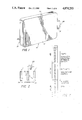
- FIG. 1 is a perspective view of a heat detector embodying this invention and having a multicolor bar graph display at an end of a housing opposite to a radiation sensor;
- FIG. 2 is a schematic illustration of use of the detector of FIG. 1 to scan a radiation source.
- FIG. 3 is an enlarged illustration of the scale of the multicolor bar graph of FIG. 1 with the guidelines recommended by insurance and utility companies.
- FIG. 4 is an electrical schematic diagram of the electrical circuit used in an embodiment of the invention having a timing circuit.
- FIG. 5 is an electrical schematic diagram of the low cost electrical circuit of another embodiment of the invention.
- FIG. 6 is an electrical schematic diagram of the electrical circuit used in an embodiment of the invention having a four LED display.
- a radiation detector 12 comprises a boxlike housing 14. This housing has an approximate dimension of 33/8" ⁇ 5" ⁇ 5/8". The flat, handheld housing can be easily carried in a pocket.
- a radiation sensor assembly 16 is positioned at one end of the housing 14.
- An LED bar graph display 18 is located at the end of the housing 14 opposite to the sensor assembly 16.
- This particular bar graph includes the scale from 0 degree centigrade to 100 degree centigrade. As shown in FIG. 3, a 0 degree to 20 degree part of the scale is divided into 1 degree increments. The 20 degree to 100 degree part of the scale is divided into 10 degree increments. The 0 degree to 9 degree segment is colored green indicating no need for corrective action according to the guidelines recommended by insurance and utility companies. The 10 degree to 19 degree segment is colored yellow indicating a need to reinvestigate. The 20 degree to 100 degree segment is colored red indicating a need to investigate immediately. These inspection guidelines are detailed on one side of the housing 14. The region 20 in FIG.
- the bar graph does not include a numerical scale. Instead the bar graph includes the three segments colored green, yellow and red, respectively indicating the corrective action recommended by the insurance and utility company guidelines. Further in another design of the invention the display includes the three colored segments but is not illuminated to give a full bar indication rather just a single level indication is displayed. In another design of the invention, the display has two segments colored red in addition to a green and yellow segment. The first red segment displays temperatures between about 20 degrees centigrade and 65 degrees centigrade. The second red segment displays temperatures above about 65 degrees centigrade.
- a pulsed audible signal sounds at a different pulse frequency for each colored segment of the bar graph display.
- the pulse frequency increases as the detected temperature rise increases.
- a switch to disenable the audible signal is also available in another design of the invention.
- FIG. 2 illustrates an example of the use of the device to scan a region to pinpoint a source of maximum radiation.
- the indication 20 While directed to a neutral surface as in position 24, the indication 20 is set at a low region of the scale. The indication 20 is automatically zeroed at this level and the radiation sensor is then scanned across a wide field to a position 26. Within that field, the sensor senses radiation from the light source 28. As indicated by the scale position shown schematically between the two end positions 24 and 26, the indication 20 rises to a maximum level at the position 30 at which the sensor is directed at the light source 28. Having been automatically zeroed at the ambient temperature, the indication 20 provides a reading of the temperature rise above ambient. The maximum reading is the measurement of interest and such reading is much more readily picked up by an observer using a bar graph display than a digital numerical display.
- FIG. 4 The electrical schematic diagram of the electrical circuit used in one embodiment of the invention is illustrated in FIG. 4.
- the unit is self operated for a predetermined length of time after the initial powering of the unit by way of a timing circuit which includes a 30 second counter 33.
- the initial powering of the unit begins by the user squeezing the side of the housing 14 of FIG. 1.
- the housing power is applied from the battery 82 through the switch SW 1 of FIG. 4 to the V+ regulated line which begins the counter 33.
- the switch SW 1 is manually held closed by the user long enough for the high voltage across the V+ regulated line to close switch K1 through coil K2 connected to switch K1.
- Switch K1 maintains connection of the 9 V Battery 82 to lines powering the rest of the circuit.
- Switch SW 2 is connected to switch SW 1 and thereby is closed at the same time. The closing of switch SW 2 resets and powers up the autozero circuit 48, and sets D flip flop 31.
- the autozero circuit 48 produces a negative reference signal which is applied through buffer 47 to the summing node 66 where it is summed with a subsequent negative radiation signal from IR sensor 83. This summed voltage is amplified in amplifier 67. The output voltage from amplifier 67 triggers the display 78 to provide an indication of the sensed radiation.
- the output voltage from amplifier 67 also controls the voltage to frequency device 92 which controls the pulse frequency of buzzer 70.
- the output voltage is offset at comparator 90 to produce the lowest duty cycle of the voltage of frequency device 92 at ambient.
- the output voltage from amplifier 67 causes the voltage to frequency device 92 to pulse the clock of the D flip flop 32.
- the D flip flop 32 produces output Q directly from input D.
- Output Q leads into the D input of D flip flop 32 so that after each pulsing of the clock a change in Q will result in a subsequent change in the D input so that on the next clock pulse a change in Q will occur.
- D flip flop 32 ensures a 50% duty cycle of the buzzer 70 and the frequency of the D flip flop 32 is generated by the voltage to frequency device 92.
- the buzzer 70 is refrained from sounding upon initial powering of the device by the gate 40.
- the gate 40 has a high voltage input from the output of the 30 second counter 33 and a low voltage second input from the Q output of the D Flip Flop 31. These two inputs produce a low voltage output from the gate 40 which disables the D flip flop 32, thus holding the buzzer 70 from sounding.
- D Flip flop 31 is clocked by the 1 Hz oscillator and the Q output from D Flip Flop 31 changes from a low to a high voltage, thus causing dissimilar inputs to the gate 40 and disabling the D Flip Flop 32 from further sounding the buzzer 70. Thus just before the unit shuts itself off the buzzer sounds one last time.
- the drop in voltage of the voltage output of counter 33 not only sounds the buzzer 70 but also changes the Q output of D flip flop 31 from high to low. This low voltage causes coil K2 to open switch K1 and thereby shuts off the unit. A subsequent squeeze of the housing 14 resets the autozero reference signal held in buffer 47 and the 30 second counter 33 in the same manner as described above for initial powering of the device.
- Display 78 operates as follows.
- the signal from the thermopile sensor element 83 is amplified in a preamplifier 69.
- the radiation signal from the thermopile is summed with the reference signal from the autozero circuit to be described.
- the sum is amplified in an amplifier 67.
- Each display driver in display 78 responds to the amplified signal and incrementally selects light emitting diodes to light the bar graph display.
- Each display driver incrementally selects light emitting diodes based on the high and low reference inputs for that particular driver.
- the incremental change of each driver is defined at a voltage of one-tenth of the difference between the high and the lows references, there being ten light emitting diodes per driver.
- the light emitting diodes associated with each driver are linearly driven by that driver.
- the low reference of the succeeding driver is set equal to the high reference to the preceding driver.
- the voltage per incremental change of the succeeding driver is then defined by its high and low references which have a different difference than the high and low references of the preceding driver.
- the light emitting diodes selected from one display driver to the next are thus driven in a piece-wise linear fashion.
- the display drivers provide a piece-wise linear approximation of temperature which is a nonlinear function of the sensed heat flux.
- the display driver associated with the light emitting diodes for the zero degree to 9 degree end of the bar graph has a low reference to zero mV and a high reference voltage of 150 mV.
- a display driver selects each additional LED in response to a voltage step of 15 mV to indicate a temperature change of 1 degree on the bar graph.
- the low reference input to the succeeding driver is 150 mV and the high reference is 320 mV to establish a voltage step of 17 mV for each degree of change on the bar graph between the 9 degree and 19 degree segment.
- the third display driver uses references which account for both the linearization and the change in scale increment in the 20 degree to 100 degree centigrade part of the bar graph.
- the first incremental change at which the third driver responds provides the 1 degree centigrade change in temperature on the bar graph from 19 degree centigrade to 20 degrees.
- the remaining incremental changes with the third driver provide selection of the LEDs for the 10 degree increments in the 20 degree to 100 degree segment of the bar graph.
- a complication arises with the third driver because it must provide a 1 degree increment from 19 degrees to 20 degrees and 10 degree increments thereafter.
- the low reference is set at a level below 320 mV
- the high reference of the preceding driver and the high reference is set at 2.4 volts.
- the third driver therefore, responds to approximately 230 mV increments.
- the large incremental change to which the driver responds sets the first trigger level at about (0.106+0.230) or at 0.336 mV. This is approximately the input to which the second driver would have responded if it had one more stage responding to 17 mV increments. Beyond the 0.336 mV, the driver increments the display at 230 mV increments. Those increments account for the third piece of the piece-wise linear approximately of temperature with ten degree increments.
- the display is automatically zeroed at the ambient temperature of the neutral surface at which the device is first pointed, using an autozero circuit as commonly known in the art.
- power is applied from the battery 82 through switch K1 to the entire circuit.
- the transition to a high potential results in a positive pulse at an opposite side of a capacitor in autozero circuit 48 which triggers a comparator.
- a negative pulse results at the output of the comparator to draw current through a diode and a resistor and place a negative charge on a reference capacitor. That negative potential is applied through a buffer 47 to the summing node 66 where it is summed with the negative radiation signal.
- the charge initially placed on the reference capacitor establishes a high negative reference signal which results in the display 78 being set well above the zero degree centigrade level of the bar graph.
- the high reference signal is then reduced by bleeding the charge from the reference capacitor until the display 78 reachbes the zero level of the bar graph.
- the reference signal is reduced at a decreasing rate as the display 78 approaches the zero level of the bar graph. This is accomplished by tapping the input to the LED at the 10 degree level of the bar graph so that when the display 78 reaches this level, a D flip-flop opens one switch reducing the rate at which charge is bled off from the reference capacitor.
- input to the LED at the zero degree level of the bar graph is tapped to provide an indication of the display 78 approaching the zero degree level.
- a second D flip-flop is then triggered and a second switch stops the bleeding of charge from the reference capacitor.
- the amount of charge of the reduced reference signal is inversely related to the radiation sensed from the ambient surface and is reproduced at the output of buffer 47 to be added to each signal from the radiation sensor 83 throughout the scan.
- the display 78 is thus autozeroed and provides readings of the temperature rise above ambient.
- FIG. 5 Shown in FIG. 5 is another embodiment of the invention with a different autozero circuit than in the embodiment of FIG. 4 and which is designed for the minimization of production costs.
- the autozero circuit of the embodiment in FIG. 5 may also be used in the embodiment of FIG. 4.
- an autozero reference signal is established by the user closing switch 15 which is the power switch connecting the 9 v battery 9 to the V+ and other lines of the circuit.
- the radiation sensor 13 detects the radiation of the object at which the device is initially pointing. Provided that the initial object is at a temperature above ambient, the sensed radiation produces a negative voltage which is applied through the dual operational amplifiers 21 and 23 to produce a gain in voltage.
- Switch 25 is closed by timer 11 when the device is turned on. Switch 25 allows the negative voltage to charge the capacitor 19 to a level indicative of the temperature of the object toward which the device initially points.
- Timer 11 holds switch 25 closed about 500 msec which is long enough for the capacitor 19 to be charged by the initial negative voltage from the radiation sensor 13. At the end of the 500 msec, the timer opens switch 25 to discontinue the charging of the capacitor 19.
- the initial high voltage output of the timer 11 also holds the buzzer 80 off and disables the display decoder 75 while the capacitor 19 is being charged. After the allotted time, the timer output voltage drops to reset the buzzer 80 and enable the 2 to 4 decoder 75.
- the enablement of the decoder causes the green LED to light, thus signifying that the unit has been autozeroed.
- the negative charge held by the capacitor 19 is applied to a buffer 27.
- the negative voltage output of buffer 27 is the autozero reference signal which is later input to differential amplifier 29 with subsequent radiation signals from amplifier 23 indicative of temperatures sensed by sensor 13.
- the output voltage from amplifier 29 is a positive voltage indicative of the difference between the reference temperature and the temperature being observed.
- the voltage drives comparators 71 and 73 to produce inputs at ⁇ A ⁇ and ⁇ B ⁇ of the 2 to 4 decoder 75.
- the second inputs to the comparators are taken from a voltage divider of resistors 87, 88 and 89 which divides the reference voltage from the reference voltage generator 91. With low temperatures the output voltage from differential amplifier 29 is less than that across resistor 89 and neither comparator is enabled.
- the decoder 75 selects one of three outputs placing a high voltage on one of three display LED's connected to the decoder outputs. If the voltage differential is below about 166 mv then comparators 71 and 73 produce low outputs to the decoder inputs ⁇ A ⁇ and ⁇ B ⁇ producing a high voltage output of the decoder 75 at Q 0 which illuminates just the green LED. 166 mv is the amount of voltage that would result from detecting a 10 degree centigrade rise in target temperature above ambient.
- comparator 73 places a high voltage input at ⁇ A ⁇ and comparator 71 places a low voltage at input ⁇ B ⁇ . Those inputs are decoded to produce a high voltage output at Q 1 to illuminate just the yellow LED. The green LED is dimmed at output Q 0 is now low. 317 mv is the amount of voltage indicative of a 20 degree centrigrade change in sensed temperature. If the differential voltage is above about 317 mv then there are high inputs to decoder 75 at both ⁇ A ⁇ and ⁇ B ⁇ , producing a high output at Q 3 which illuminates just the red LED and low outputs at Q 0 and Q 1 which dim the green and yellow LED's.
- the output voltage from amplifier 29 also controls the voltage to frequency device 10. This voltage is offset by the reference voltage, preferably about 2.5 v to 3.4 v from VREF91 at comparator 8 to produce the lowest duty cycle of the voltage to frequency node 10 at ambient.
- the output voltage from amplifier 29 causes the voltage to frequency node 10 to pulse the clock of the D flip flop 17. Each time the clock is pulsed, the D flip flop 17 has an output Q directly dependent upon input D.
- the output Q is connected to the D input so that after each pulsing of the clock a change in Q will result in a subsequent change in D which in turn produces a change in Q on the next pulse of the clock.
- the D flip flop 17 ensures a 50% duty cycle of the buzzer 80 and the frequency of the D flip flop 17 is generated by the voltage to frequency device 10.
- the voltage to frequency device 10 produces a more frequent clocking signal to D flip flop 17 which causes an increase in the pulsing frequency of buzzer 80.
- the output voltage from amplifier 29 increases to produce an increase in pulse frequency of the buzzer 80.
- the increasing pulse frequencies of the buzzer 80 correspond to the green, yellow and red LED's respectively.
- a slow continuous pulse frequency sounds for the temperatures sensed in the range of temperatures illuminating the green LED.
- the pulse frequency increases for increasing temperatures within the green LED range and continues to increase through the yellow and red LED temperature range.
- the user can disable the buzzer 80 for situations where the audible signal is not wanted.
- a four LED display is driven by three comparators and a 3 to 8 decoder as shown in FIG. 6.
- the rest of the electrical circuit is the same as in the embodiment of FIG. 5.
- the four LED's of the display are colored green, yellow, red, and a second red respectively.
- One LED at a time is illuminated.
- the green LED signifies a temperature rise above ambient of up to about 10 degrees centigrade.
- the yellow is illuminated for a sensed temperature rise between about 10 and 20 degrees centigrade.
- the first red LED is illuminated for sensed temperature rise between about 20 and 65 degrees centigrade.
- the second red LED is illuminated for sensed temperature rise above about 65 degrees centigrade.
- Power switch 55 is closed by the user upon operation of the device. Power switch 55 connects battery 39 to the lines of the circuit. Timer 6 is in turn powered and closes switch 62 for about 0.5 seconds. During this interval, the negative voltage produced by the IR sensor corresponds to the ambient object at which the device is pointing. This voltage is amplified by amplifiers 41 and 44, and stored on capacitor 64. The timer 6 also holds buzzer 43 off and disables the decoder 45 powering the display until the capacitor 64 is charged. At the end of the 0.5 seconds, the timer 6 opens switch 62 to discontinue the charging of capacitor 64, reset the buzzer 43, and enables the decoder 45 allowing the green LED to light signifying that the device is autozeroed.
- the negative charge held by capacitor 64 is applied to buffer 46.
- the negative voltage output of buffer 46 is the autozero reference signal which is later input to differential amplifier 56 with radiation signals from amplifier 44 indicative of temperatures sensed by sensor 37.
- the output is about 7.39 mv/btu/hr/sq ft sensed above or below the autozero target. That is, the output voltage from amplifier 56 is a voltage indicative of the difference between the reference temperature and the temperature being observed.
- the voltage drives comparators 63, 72, and 76 to produce inputs to a 3 to 8 decoder 45.
- the second inputs to the comparators are taken from a voltage divider of resistors 54, 3, 7 and 5 which divides the 2.53 V reference voltage from reference voltage generator 85 into voltages corresponding to the sensed change in radiation with the change in temperatures of the display. With a low sensed change in radiation, the output voltage from amplifier 56 is less than that across resistor 5 and none of the three comparators are enabled. The decoder 45 in turn illuminates only the green LED. With a somewhat higher change in sensed radiation, the output voltage surpasses that across resistor 5, and comparator 76 is enabled. Comparator 76 then places a high input to decoder 45 which causes the decoder to illuminate the yellow LED and dim the green LED.
- Comparator 72 With a higher change in sensed radiation the voltage across resistors 3 and 7 is matched and comparator 72 is enabled. Comparator 72 in turn places a high input to decoder 45 which causes the first red LED to be illuminated and the yellow LED to be dimmed. With yet a higher change in sensed radiation, the voltage across resistors 54 and 3 is matched and comparator 63 is enabled. Comparator 63 places a high input to decoder 45 which in turn selects to illuminate just the second red LED.
- the output voltage from amplifier 56 also controls the voltage to frequency device 60 which pulses the clock of D flip flop 68 sounding buzzer 43 in a manner similar to that described in the circuit of FIG. 5.
- the output voltage is offset by the reference voltage from reference voltage generator 85 at comparator 52 so that the voltage to frequency device 60 is at its lowest frequency at ambient and at its highest frequency when near the 20 degree centigrade sensed change in radiation threshhold. Once this threshhold is crossed the buzzer 43 will sound continuously.
- the buzzer sounds with increasing pulse frequency corresponding to the green, yellow, and two red LED's respectively in the same manner as the buzzer 80 in the embodiment of FIG. 5.
- the buzzer 43 can be disabled by the user pressing switch 22 for applications where the audible signal is not wanted.
- Wavelengths are shorter from hotter sources of radiation.
- the device must detect wavelengths which are short relative to those from bodies at ambient temperature.
- the radiation from the very hot sun is of very short wavelengths and sunlight should not be detected.
- overheated electrical connectors have relatively long wavelengths which can be readily distinguished with a wide range of filters.
- a further consideration, however, is that a user is likely to want to assure proper operation of a device by viewing a known hot source such as a match or light bulb. Such sources produce radiation of wavelengths much closer to those of sunlight and require much more specific filtering to allow for their detection to the exclusion of sunlight.
- a window 86 made of germanium covers the radiation sensor within the radiation sensor assembly 16 of FIG. 1.
- a lens comprising germanium is also suitable.
- the germanium window 86 or lens acts as a filter allowing only energy of certain wavelengths to be detected by the radiation sensor.
- the germanium glass filters out short wavelengths of less than about 1.7 microns from detection by the radiation sensor. 90% of the wavelengths in sunlight are less than 1.5 microns. Although the wavelengths of energy from hot electrical connectors are significantly greater than 1.5 microns, it is desirable to detect shorter wavelengths resulting from the flame of a match to assure proper operation of the unit.
- the flames of interest are on the order of about 2000° F. to 2500° F. and produce wavelengths of about 1.7 to 3 microns with a peak at about 2 microns.
- the germanium glass filters out about 90% of the sunlight energy and only rejects about 10% of the energy of a flame.
- the germanium window 86 serves a further purpose of preventing sunlight from burning out the sensor. Because the wavelengths of sunlight and other visible light are short, less than about 1.5 microns, it takes a very short time of exposure to such light to over expose and thus burn out the sensor. Hence, by the germanium window 86 filtering out the short wavelengths of sunlight and other visible light, the sensor is safeguarded against over exposure and subsequent burn out.
- coated germanium windows were used as long wave pass filters. Coated germanium starts passing wavelengths at about 7 to 8 microns. Thus a coated germanium window would not allow detection of the shorter wavelengths of a flame test. Consequently, applicant uses uncoated germanium glass for window 86.
- ordinary glass filters out wavelengths less than about 3 microns. Ordinary glass rejects about 30-40% of the wavelengths of a flame. Other glass filters, however, are suitable and may be used in place of window 86. In general, it is best to have a filter and sensor which provides a threshold between about 1.5 and 3.0 microns.
- Another problem with the outdoor use of past detectors is the glare from sunlight causing difficulties in reading the detector display.
- this problem is overcome by the audio indication of the detected temperature rise above ambient.
- a continuous, slow pulsing ⁇ beep ⁇ tone indicates that a minimal temperature above ambient is being detected.
- ⁇ Beeps ⁇ at a faster pulse frequency indicate that a greater temperature is being detected.
- the user is made aware of a detected dangerous level of temperature rise by a ⁇ beep ⁇ signal sounding at a pulse frequency faster than the other two mentioned frequencies.
- the use of the detector is not dependent on a light display which is often difficult to read in sunlight. This feature of an audible indication of the detected temperature is discussed and described above.
- the audible indication provides a means to alert the user of a temperature rise while scanning a subject. Once the user is alerted by an increase in pulse frequency, a quantitative analysis of the sensed temperature rise may be obtained by the display. Hence, the user can scan a subject without specifically knowing where to look for potential heat problems, locate the problem area with the audible signal, and now knowing where to focus the detector quantify the detected radiation with the display.
Abstract
Description
Claims (34)
Priority Applications (2)
| Application Number | Priority Date | Filing Date | Title |
|---|---|---|---|
| US07/032,067 US4874253A (en) | 1987-03-27 | 1987-03-27 | Radiation detector with temperature display |
| US08/222,324 USRE35554E (en) | 1987-03-27 | 1994-04-04 | Radiation detector with temperature display |
Applications Claiming Priority (1)
| Application Number | Priority Date | Filing Date | Title |
|---|---|---|---|
| US07/032,067 US4874253A (en) | 1987-03-27 | 1987-03-27 | Radiation detector with temperature display |
Related Child Applications (1)
| Application Number | Title | Priority Date | Filing Date |
|---|---|---|---|
| US08/222,324 Reissue USRE35554E (en) | 1987-03-27 | 1994-04-04 | Radiation detector with temperature display |
Publications (1)
| Publication Number | Publication Date |
|---|---|
| US4874253A true US4874253A (en) | 1989-10-17 |
Family
ID=21862915
Family Applications (1)
| Application Number | Title | Priority Date | Filing Date |
|---|---|---|---|
| US07/032,067 Ceased US4874253A (en) | 1987-03-27 | 1987-03-27 | Radiation detector with temperature display |
Country Status (1)
| Country | Link |
|---|---|
| US (1) | US4874253A (en) |
Cited By (25)
| Publication number | Priority date | Publication date | Assignee | Title |
|---|---|---|---|---|
| WO1990006558A1 (en) * | 1988-12-09 | 1990-06-14 | Campsport, Inc. | Personal multi-purpose navigational apparatus and method for operation thereof |
| US5017019A (en) * | 1989-04-14 | 1991-05-21 | Exergen Corporation | Radiation detector for differential biological temperature readings |
| US5094544A (en) * | 1990-10-19 | 1992-03-10 | Square D Company | Scanning infrared thermometer with DC offset and emissivity correction |
| US5285396A (en) * | 1991-01-11 | 1994-02-08 | Tadamasa Aoyama | Device for evaluating race horse performance based on temperature |
| US5369416A (en) * | 1992-06-17 | 1994-11-29 | Indikon Company, Inc. | Multi-color bargraph |
| US5678925A (en) * | 1995-10-16 | 1997-10-21 | Garmaise; Ian | Temperature sensing and indicating beverage mug |
| US5820263A (en) * | 1996-07-15 | 1998-10-13 | Ciobanu; Sorin G. | Apparatus and method for monitoring the temperature of a region of human tissue |
| US5833367A (en) | 1996-11-12 | 1998-11-10 | Trutek, Inc. | Tympanic thermometer probe cover |
| US5967992A (en) | 1998-06-03 | 1999-10-19 | Trutex, Inc. | Radiometric temperature measurement based on empirical measurements and linear functions |
| US6001066A (en) | 1997-06-03 | 1999-12-14 | Trutek, Inc. | Tympanic thermometer with modular sensing probe |
| US6030117A (en) | 1996-11-12 | 2000-02-29 | Trutek, Inc. | Tympanic thermometer probe cover |
| US6090050A (en) * | 1998-07-16 | 2000-07-18 | Salix Medical, Inc. | Thermometric apparatus and method |
| US6123454A (en) | 1999-06-11 | 2000-09-26 | Trutek, Inc. | Tympanic thermometer disposable probe cover with further stretching prevention structure |
| US6693606B1 (en) * | 1999-09-10 | 2004-02-17 | Sony Computer Entertainment Inc. | Method of and apparatus for displaying measured quantity, recording medium, and program |
| US20040240516A1 (en) * | 2002-12-12 | 2004-12-02 | James Harr | Thermal tympanic thermometer tip |
| US20050207470A1 (en) * | 2004-01-26 | 2005-09-22 | Bennett Timothy J | Focusing thermometer |
| US20060239332A1 (en) * | 2002-12-12 | 2006-10-26 | Sherwood Services Ag | Thermal tympanic thermometer |
| US20070100564A1 (en) * | 2003-08-19 | 2007-05-03 | Advanced Monitors Corporation | Medical body core thermometer |
| US20070187605A1 (en) * | 2005-12-12 | 2007-08-16 | Suren Systems, Ltd. | Temperature Detecting System and Method |
| US7306565B2 (en) | 2000-09-15 | 2007-12-11 | Advanced Monitors Corporation | Ear temperature monitor and method of temperature measurement |
| WO2009151852A1 (en) * | 2008-06-09 | 2009-12-17 | Black & Decker Inc. | Non-contact thermometer |
| US7785266B2 (en) | 2003-08-19 | 2010-08-31 | Advanced Monitors Corporation | Medical thermometer for determining body core temperature |
| EP2415975A1 (en) * | 2010-08-05 | 2012-02-08 | General Electric Company | Thermal measurement system for fault detection within a power generation system |
| WO2012092424A1 (en) | 2010-12-30 | 2012-07-05 | Exergen Corporation | Infrared sensor and method for electrical monitoring |
| US9097182B2 (en) | 2010-08-05 | 2015-08-04 | General Electric Company | Thermal control system for fault detection and mitigation within a power generation system |
Citations (15)
| Publication number | Priority date | Publication date | Assignee | Title |
|---|---|---|---|---|
| US3444739A (en) * | 1965-12-22 | 1969-05-20 | Kettering Scient Research Inc | Radiant energy measuring instrument |
| US3777568A (en) * | 1971-12-21 | 1973-12-11 | Sensors Inc | D. c. electronic apparatus for ir radiation temperature measurement |
| US4081678A (en) * | 1976-03-01 | 1978-03-28 | Macall Thomas F | Through-the-lens thermometer apparatus |
| US4317998A (en) * | 1975-06-18 | 1982-03-02 | The Secretary Of State For Defence In Her Britannic Majesty's Government Of The United Kingdom Of Great Britain And Northern Ireland | Infra-red line-scanning target detectors |
| US4321594A (en) * | 1979-11-01 | 1982-03-23 | American District Telegraph Company | Passive infrared detector |
| US4343182A (en) * | 1980-07-14 | 1982-08-10 | Exergen Corporation | Radiation heat loss detector |
| US4372690A (en) * | 1981-03-06 | 1983-02-08 | Linear Corporation | Thermal radiation measuring arrangement |
| US4420265A (en) * | 1981-07-31 | 1983-12-13 | Everest Charles E | Infrared temperature monitoring apparatus having means for sky radiation compensation |
| US4456390A (en) * | 1981-10-26 | 1984-06-26 | Wahl Instruments, Inc. | Noncontact temperature measuring device |
| US4481417A (en) * | 1982-09-22 | 1984-11-06 | The Boeing Company | Infrared energy detection device |
| US4566808A (en) * | 1983-02-16 | 1986-01-28 | Exergen Corporation | Scanning radiation detector |
| US4596932A (en) * | 1983-05-17 | 1986-06-24 | Allied Memorial Hospital For Cancer & Diseases | Portable dosimeter |
| US4636091A (en) * | 1985-06-27 | 1987-01-13 | Exergen Corporation | Radiation detector having temperature readout |
| US4730940A (en) * | 1984-03-10 | 1988-03-15 | Gruen Analysengeraete Gmbh | Device for pyrometric temperature measurement |
| US4784149A (en) * | 1986-01-13 | 1988-11-15 | Optical Sensors, Inc. | Infrared thermometer with automatic calibration |
-
1987
- 1987-03-27 US US07/032,067 patent/US4874253A/en not_active Ceased
Patent Citations (15)
| Publication number | Priority date | Publication date | Assignee | Title |
|---|---|---|---|---|
| US3444739A (en) * | 1965-12-22 | 1969-05-20 | Kettering Scient Research Inc | Radiant energy measuring instrument |
| US3777568A (en) * | 1971-12-21 | 1973-12-11 | Sensors Inc | D. c. electronic apparatus for ir radiation temperature measurement |
| US4317998A (en) * | 1975-06-18 | 1982-03-02 | The Secretary Of State For Defence In Her Britannic Majesty's Government Of The United Kingdom Of Great Britain And Northern Ireland | Infra-red line-scanning target detectors |
| US4081678A (en) * | 1976-03-01 | 1978-03-28 | Macall Thomas F | Through-the-lens thermometer apparatus |
| US4321594A (en) * | 1979-11-01 | 1982-03-23 | American District Telegraph Company | Passive infrared detector |
| US4343182A (en) * | 1980-07-14 | 1982-08-10 | Exergen Corporation | Radiation heat loss detector |
| US4372690A (en) * | 1981-03-06 | 1983-02-08 | Linear Corporation | Thermal radiation measuring arrangement |
| US4420265A (en) * | 1981-07-31 | 1983-12-13 | Everest Charles E | Infrared temperature monitoring apparatus having means for sky radiation compensation |
| US4456390A (en) * | 1981-10-26 | 1984-06-26 | Wahl Instruments, Inc. | Noncontact temperature measuring device |
| US4481417A (en) * | 1982-09-22 | 1984-11-06 | The Boeing Company | Infrared energy detection device |
| US4566808A (en) * | 1983-02-16 | 1986-01-28 | Exergen Corporation | Scanning radiation detector |
| US4596932A (en) * | 1983-05-17 | 1986-06-24 | Allied Memorial Hospital For Cancer & Diseases | Portable dosimeter |
| US4730940A (en) * | 1984-03-10 | 1988-03-15 | Gruen Analysengeraete Gmbh | Device for pyrometric temperature measurement |
| US4636091A (en) * | 1985-06-27 | 1987-01-13 | Exergen Corporation | Radiation detector having temperature readout |
| US4784149A (en) * | 1986-01-13 | 1988-11-15 | Optical Sensors, Inc. | Infrared thermometer with automatic calibration |
Non-Patent Citations (1)
| Title |
|---|
| Microscanner E., Exergen Corporation Brochure, 1985. * |
Cited By (43)
| Publication number | Priority date | Publication date | Assignee | Title |
|---|---|---|---|---|
| WO1990006558A1 (en) * | 1988-12-09 | 1990-06-14 | Campsport, Inc. | Personal multi-purpose navigational apparatus and method for operation thereof |
| US4977509A (en) * | 1988-12-09 | 1990-12-11 | Campsport, Inc. | Personal multi-purpose navigational apparatus and method for operation thereof |
| US5017019A (en) * | 1989-04-14 | 1991-05-21 | Exergen Corporation | Radiation detector for differential biological temperature readings |
| US5094544A (en) * | 1990-10-19 | 1992-03-10 | Square D Company | Scanning infrared thermometer with DC offset and emissivity correction |
| US5285396A (en) * | 1991-01-11 | 1994-02-08 | Tadamasa Aoyama | Device for evaluating race horse performance based on temperature |
| US5369416A (en) * | 1992-06-17 | 1994-11-29 | Indikon Company, Inc. | Multi-color bargraph |
| US5678925A (en) * | 1995-10-16 | 1997-10-21 | Garmaise; Ian | Temperature sensing and indicating beverage mug |
| US5820263A (en) * | 1996-07-15 | 1998-10-13 | Ciobanu; Sorin G. | Apparatus and method for monitoring the temperature of a region of human tissue |
| US5833367A (en) | 1996-11-12 | 1998-11-10 | Trutek, Inc. | Tympanic thermometer probe cover |
| US6030117A (en) | 1996-11-12 | 2000-02-29 | Trutek, Inc. | Tympanic thermometer probe cover |
| US6042266A (en) | 1996-11-12 | 2000-03-28 | Trutek, Inc. | Tympanic thermometer probe cover |
| US6001066A (en) | 1997-06-03 | 1999-12-14 | Trutek, Inc. | Tympanic thermometer with modular sensing probe |
| US6186959B1 (en) | 1997-06-03 | 2001-02-13 | Trutek, Inc. | Tympanic thermometer with modular sensing probe |
| US5967992A (en) | 1998-06-03 | 1999-10-19 | Trutex, Inc. | Radiometric temperature measurement based on empirical measurements and linear functions |
| US6090050A (en) * | 1998-07-16 | 2000-07-18 | Salix Medical, Inc. | Thermometric apparatus and method |
| US6123454A (en) | 1999-06-11 | 2000-09-26 | Trutek, Inc. | Tympanic thermometer disposable probe cover with further stretching prevention structure |
| US6693606B1 (en) * | 1999-09-10 | 2004-02-17 | Sony Computer Entertainment Inc. | Method of and apparatus for displaying measured quantity, recording medium, and program |
| US7306565B2 (en) | 2000-09-15 | 2007-12-11 | Advanced Monitors Corporation | Ear temperature monitor and method of temperature measurement |
| US20060239332A1 (en) * | 2002-12-12 | 2006-10-26 | Sherwood Services Ag | Thermal tympanic thermometer |
| US20040240516A1 (en) * | 2002-12-12 | 2004-12-02 | James Harr | Thermal tympanic thermometer tip |
| US7434991B2 (en) | 2002-12-12 | 2008-10-14 | Covidien Ag | Thermal tympanic thermometer |
| US7108419B2 (en) | 2002-12-12 | 2006-09-19 | Sherwood Services Ag | Thermal tympanic thermometer tip |
| US7841767B2 (en) | 2002-12-12 | 2010-11-30 | Covidien Ag | Thermal tympanic thermometer |
| US7828743B2 (en) | 2003-08-19 | 2010-11-09 | Advanced Monitors Corporation | Medical body core thermometer |
| US20070100564A1 (en) * | 2003-08-19 | 2007-05-03 | Advanced Monitors Corporation | Medical body core thermometer |
| US7938783B2 (en) | 2003-08-19 | 2011-05-10 | Advanced Monitors Corporation | Medical body core thermometer |
| US7785266B2 (en) | 2003-08-19 | 2010-08-31 | Advanced Monitors Corporation | Medical thermometer for determining body core temperature |
| US20050207470A1 (en) * | 2004-01-26 | 2005-09-22 | Bennett Timothy J | Focusing thermometer |
| US7498576B2 (en) * | 2005-12-12 | 2009-03-03 | Suren Systems, Ltd. | Temperature detecting system and method |
| US20070187605A1 (en) * | 2005-12-12 | 2007-08-16 | Suren Systems, Ltd. | Temperature Detecting System and Method |
| EP2288885A4 (en) * | 2008-06-09 | 2015-04-15 | Black & Decker Inc | Non-contact thermometer |
| EP2288885A1 (en) * | 2008-06-09 | 2011-03-02 | Black & Decker Inc. | Non-contact thermometer |
| WO2009151852A1 (en) * | 2008-06-09 | 2009-12-17 | Black & Decker Inc. | Non-contact thermometer |
| EP2415975A1 (en) * | 2010-08-05 | 2012-02-08 | General Electric Company | Thermal measurement system for fault detection within a power generation system |
| CN102419210A (en) * | 2010-08-05 | 2012-04-18 | 通用电气公司 | Thermal measurement system for fault detection within a power generation system |
| US9019108B2 (en) | 2010-08-05 | 2015-04-28 | General Electric Company | Thermal measurement system for fault detection within a power generation system |
| US9097182B2 (en) | 2010-08-05 | 2015-08-04 | General Electric Company | Thermal control system for fault detection and mitigation within a power generation system |
| CN102419210B (en) * | 2010-08-05 | 2016-02-03 | 通用电气公司 | For the thermal measurement system of the fault detect in electricity generation system |
| WO2012092424A1 (en) | 2010-12-30 | 2012-07-05 | Exergen Corporation | Infrared sensor and method for electrical monitoring |
| US9170158B2 (en) | 2010-12-30 | 2015-10-27 | Exergen Corporation | Infrared sensor and method for electrical monitoring |
| US9759609B2 (en) | 2010-12-30 | 2017-09-12 | Exergen Corporation | Infrared sensor and method for electrical monitoring |
| US10126173B2 (en) | 2010-12-30 | 2018-11-13 | Exergen Corporation | Infrared sensor and method for electrical monitoring |
| US10605664B2 (en) | 2010-12-30 | 2020-03-31 | Exergen Corporation | Infrared sensor and method for electrical monitoring |
Similar Documents
| Publication | Publication Date | Title |
|---|---|---|
| US4874253A (en) | Radiation detector with temperature display | |
| USRE35554E (en) | Radiation detector with temperature display | |
| US4831258A (en) | Dual sensor radiation detector | |
| US4900162A (en) | Infrared thermometry system and method | |
| US20130283890A1 (en) | Laser indicator for remote measuring devices and method therefor | |
| EP0747682B1 (en) | Temperature measuring apparatus | |
| US5839821A (en) | Flashlight with forward looking sensing of thermal bodies | |
| US4821338A (en) | Optical signal receiving apparatus with compensation for peripheral light | |
| US5132631A (en) | Glass surface coating detector | |
| JPH0617826B2 (en) | Pyrometer | |
| US20070104246A1 (en) | Digital thermometer | |
| JP2001505994A (en) | Digital thermometer and temperature measurement end notification method | |
| CN110880230A (en) | Intelligent combustible gas detector and alarm method | |
| US4481417A (en) | Infrared energy detection device | |
| JP2604754B2 (en) | Spectrophotometer | |
| CN111289120A (en) | Low-cost fixed-distance infrared temperature measuring device and method | |
| JP2002539426A (en) | Gas sensor and method of operating gas sensor | |
| CN209166467U (en) | A kind of background inhibition photoelectric sensor | |
| CA2096548A1 (en) | Ionization type smoke detector | |
| US5483922A (en) | Apparatus for detecting when birds are in a birdhouse | |
| US5153424A (en) | Flux monitor high light intensity cut-off circit for night vision devices | |
| CN211294135U (en) | Intelligent combustible gas detector | |
| CN213985404U (en) | Infrared thermometer with ear temperature and forehead temperature prompting by adopting two sound volumes | |
| CN206835419U (en) | A kind of automatic switch and the intelligent desk lamp of light modulation | |
| CN211527622U (en) | Low-cost fixed-distance infrared temperature measuring device |
Legal Events
| Date | Code | Title | Description |
|---|---|---|---|
| AS | Assignment |
Owner name: EXERGEN CORPORATION, 251 W. CENTRAL STREET, NATICK Free format text: ASSIGNMENT OF ASSIGNORS INTEREST.;ASSIGNORS:POMPEI, FRANCESCO;BURKE, MICHAEL W.;REEL/FRAME:004703/0152 Effective date: 19870323 Owner name: EXERGEN CORPORATION, A CORP. OF MASSACHUSETTS,MAS Free format text: ASSIGNMENT OF ASSIGNORS INTEREST;ASSIGNORS:POMPEI, FRANCESCO;BURKE, MICHAEL W.;REEL/FRAME:004703/0152 Effective date: 19870323 |
|
| CC | Certificate of correction | ||
| RF | Reissue application filed |
Effective date: 19911016 |
|
| FPAY | Fee payment |
Year of fee payment: 4 |
|
| RF | Reissue application filed |
Effective date: 19940404 |
|
| AS | Assignment |
Owner name: NATIONAL BANK OF CANADA, MASSACHUSETTS Free format text: SECURITY INTEREST;ASSIGNOR:EXERGEN CORPORATION;REEL/FRAME:008119/0133 Effective date: 19961015 |
|
| FPAY | Fee payment |
Year of fee payment: 8 |
|
| LAPS | Lapse for failure to pay maintenance fees | ||
| STCH | Information on status: patent discontinuation |
Free format text: PATENT EXPIRED DUE TO NONPAYMENT OF MAINTENANCE FEES UNDER 37 CFR 1.362 |
|
| FP | Lapsed due to failure to pay maintenance fee |
Effective date: 20011017 |
|
| AS | Assignment |
Owner name: PNC BANK, NATIONAL ASSOCIATION, PENNSYLVANIA Free format text: ASSIGNMENT OF ASSIGNORS INTEREST;ASSIGNOR:NATIONAL BANK OF CANADA;REEL/FRAME:012813/0319 Effective date: 20020115 |
|
| AS | Assignment |
Owner name: MASSACHUSETTS CAPITAL RESOURCE COMPANY, MASSACHUSE Free format text: SECURITY INTEREST;ASSIGNOR:EXERGEN CORPORATION;REEL/FRAME:012875/0738 Effective date: 20011231 |