US4870292A - Fibre optic sensor for liquid level and other parameters - Google Patents
Fibre optic sensor for liquid level and other parameters Download PDFInfo
- Publication number
- US4870292A US4870292A US07/168,481 US16848188A US4870292A US 4870292 A US4870292 A US 4870292A US 16848188 A US16848188 A US 16848188A US 4870292 A US4870292 A US 4870292A
- Authority
- US
- United States
- Prior art keywords
- optical
- fluid
- fibre
- source
- light
- Prior art date
- Legal status (The legal status is an assumption and is not a legal conclusion. Google has not performed a legal analysis and makes no representation as to the accuracy of the status listed.)
- Expired - Fee Related
Links
- 239000000835 fiber Substances 0.000 title claims abstract description 40
- 239000007788 liquid Substances 0.000 title claims description 41
- 239000012530 fluid Substances 0.000 claims abstract description 26
- 230000003287 optical effect Effects 0.000 claims abstract description 25
- 239000000758 substrate Substances 0.000 claims abstract description 20
- 239000000463 material Substances 0.000 claims abstract description 17
- 230000008878 coupling Effects 0.000 claims abstract description 7
- 238000010168 coupling process Methods 0.000 claims abstract description 7
- 238000005859 coupling reaction Methods 0.000 claims abstract description 7
- 239000013307 optical fiber Substances 0.000 claims description 44
- 238000000034 method Methods 0.000 claims description 4
- 238000005259 measurement Methods 0.000 claims description 3
- 230000004044 response Effects 0.000 claims description 3
- 125000006850 spacer group Chemical group 0.000 claims description 3
- 230000000737 periodic effect Effects 0.000 claims 1
- 239000011162 core material Substances 0.000 description 6
- 239000000446 fuel Substances 0.000 description 5
- XLYOFNOQVPJJNP-UHFFFAOYSA-N water Substances O XLYOFNOQVPJJNP-UHFFFAOYSA-N 0.000 description 4
- 238000001514 detection method Methods 0.000 description 3
- 238000004806 packaging method and process Methods 0.000 description 3
- 230000008859 change Effects 0.000 description 2
- 238000005253 cladding Methods 0.000 description 2
- 230000001902 propagating effect Effects 0.000 description 2
- 239000000126 substance Substances 0.000 description 2
- 239000004593 Epoxy Substances 0.000 description 1
- 239000004677 Nylon Substances 0.000 description 1
- 238000005452 bending Methods 0.000 description 1
- 230000001419 dependent effect Effects 0.000 description 1
- 238000006073 displacement reaction Methods 0.000 description 1
- 230000000694 effects Effects 0.000 description 1
- 230000007613 environmental effect Effects 0.000 description 1
- 230000005284 excitation Effects 0.000 description 1
- 239000007792 gaseous phase Substances 0.000 description 1
- 239000011521 glass Substances 0.000 description 1
- 230000006872 improvement Effects 0.000 description 1
- 238000011835 investigation Methods 0.000 description 1
- 238000012423 maintenance Methods 0.000 description 1
- 230000007246 mechanism Effects 0.000 description 1
- 229920001778 nylon Polymers 0.000 description 1
- 239000004033 plastic Substances 0.000 description 1
- 239000000523 sample Substances 0.000 description 1
- 238000000926 separation method Methods 0.000 description 1
- 229910052724 xenon Inorganic materials 0.000 description 1
- FHNFHKCVQCLJFQ-UHFFFAOYSA-N xenon atom Chemical compound [Xe] FHNFHKCVQCLJFQ-UHFFFAOYSA-N 0.000 description 1
Images


Classifications
-
- G—PHYSICS
- G01—MEASURING; TESTING
- G01F—MEASURING VOLUME, VOLUME FLOW, MASS FLOW OR LIQUID LEVEL; METERING BY VOLUME
- G01F23/00—Indicating or measuring liquid level or level of fluent solid material, e.g. indicating in terms of volume or indicating by means of an alarm
- G01F23/22—Indicating or measuring liquid level or level of fluent solid material, e.g. indicating in terms of volume or indicating by means of an alarm by measuring physical variables, other than linear dimensions, pressure or weight, dependent on the level to be measured, e.g. by difference of heat transfer of steam or water
- G01F23/28—Indicating or measuring liquid level or level of fluent solid material, e.g. indicating in terms of volume or indicating by means of an alarm by measuring physical variables, other than linear dimensions, pressure or weight, dependent on the level to be measured, e.g. by difference of heat transfer of steam or water by measuring the variations of parameters of electromagnetic or acoustic waves applied directly to the liquid or fluent solid material
- G01F23/284—Electromagnetic waves
- G01F23/292—Light, e.g. infrared or ultraviolet
- G01F23/2921—Light, e.g. infrared or ultraviolet for discrete levels
- G01F23/2922—Light, e.g. infrared or ultraviolet for discrete levels with light-conducting sensing elements, e.g. prisms
- G01F23/2925—Light, e.g. infrared or ultraviolet for discrete levels with light-conducting sensing elements, e.g. prisms using electrical detecting means
- G01F23/2927—Light, e.g. infrared or ultraviolet for discrete levels with light-conducting sensing elements, e.g. prisms using electrical detecting means for several discrete levels, e.g. with more than one light-conducting sensing element
-
- G—PHYSICS
- G01—MEASURING; TESTING
- G01F—MEASURING VOLUME, VOLUME FLOW, MASS FLOW OR LIQUID LEVEL; METERING BY VOLUME
- G01F23/00—Indicating or measuring liquid level or level of fluent solid material, e.g. indicating in terms of volume or indicating by means of an alarm
- G01F23/22—Indicating or measuring liquid level or level of fluent solid material, e.g. indicating in terms of volume or indicating by means of an alarm by measuring physical variables, other than linear dimensions, pressure or weight, dependent on the level to be measured, e.g. by difference of heat transfer of steam or water
- G01F23/28—Indicating or measuring liquid level or level of fluent solid material, e.g. indicating in terms of volume or indicating by means of an alarm by measuring physical variables, other than linear dimensions, pressure or weight, dependent on the level to be measured, e.g. by difference of heat transfer of steam or water by measuring the variations of parameters of electromagnetic or acoustic waves applied directly to the liquid or fluent solid material
- G01F23/284—Electromagnetic waves
- G01F23/292—Light, e.g. infrared or ultraviolet
- G01F23/2921—Light, e.g. infrared or ultraviolet for discrete levels
- G01F23/2922—Light, e.g. infrared or ultraviolet for discrete levels with light-conducting sensing elements, e.g. prisms
- G01F23/2925—Light, e.g. infrared or ultraviolet for discrete levels with light-conducting sensing elements, e.g. prisms using electrical detecting means
-
- Y—GENERAL TAGGING OF NEW TECHNOLOGICAL DEVELOPMENTS; GENERAL TAGGING OF CROSS-SECTIONAL TECHNOLOGIES SPANNING OVER SEVERAL SECTIONS OF THE IPC; TECHNICAL SUBJECTS COVERED BY FORMER USPC CROSS-REFERENCE ART COLLECTIONS [XRACs] AND DIGESTS
- Y10—TECHNICAL SUBJECTS COVERED BY FORMER USPC
- Y10S—TECHNICAL SUBJECTS COVERED BY FORMER USPC CROSS-REFERENCE ART COLLECTIONS [XRACs] AND DIGESTS
- Y10S250/00—Radiant energy
- Y10S250/90—Optical liquid level sensors
- Y10S250/901—Optical liquid level sensors with gap between light guide elements, includes open light path preset
- Y10S250/902—Optical liquid level sensors with gap between light guide elements, includes open light path preset with closed light path preset
Definitions
- This invention relates to a method and apparatus for optically detecting a liquid level or other physical parameters.
- the level of a liquid in a vessel is detected using a float with a mechanical or magnetic coupling to an external gauge, an ultrasonic or optical transducer which measures time of flight to deduce the liquid level, or a parallel wire capacitance sensor which monitors the change in the dielectric constant between the wires associated with a change in liquid level.
- the optical fibre probe or sensor is suspended or made to protrude into the vessel and the potentially fragile sensor is exposed to damage by floating debris, vibration, and dynamic effects during filling.
- the potential for damage is increased if routine maintenance of the sensor is required due to biological or chemical fouling of the optical surface.
- the fibre optic sensors just described are exclusively for discrete level measurement, e.g. to sense whether the vessel is empty or full or at some intermediate point. A multiplicity of such point sensors generally represents an impractical configuration for a continuous liquid level measure. A continuous measure is desirable, however, for improved resolution in many applications.
- a continuous measure is desirable, however, for improved resolution in many applications.
- the dielectric properties of the optical fibre sensor are desirable from the point of view of safety with respect to spark hazard and lightning strikes but high resolution and accuracy are also desirable so that excess fuel quantities would not have to be carried, thus reducing aircraft weight and consequently fuel consumption.
- Present day aircraft fuel level sensors are for the most part capacitance type sensors which lose accuracy when the fuel becomes laden with water and the dielectric constant is changed significantly.
- liquid and air refer to any two fluids of sufficiently different refractive indices to be sensed by this refractometric technique.
- air might equally well refer to the gaseous phase of the sensed liquid or to another liquid as in the case of oil and water.
- optical fibre might equally well describe any elongated light conducting body or light guide capable of conveying light by multiple internal refractions.
- Both the point and the continuous liquid level sensors described herein consist of two fibres, a source or transmit optical fibre having one end adapted to be optically connected to an external light source, and a detector or receive optical fibre having one end adapted to be optically connected to an external light detector.
- the source and detector optical fibres each have at least the other end thereof embedded in an optically clear substrate material or window that is in contact with the liquid to be sensed such that the light exiting the source fibre is incident on the substrate to liquid or air interface at an angle between the critical angle for the liquid and the critical angle for air.
- the substrate or window material has a refractive index equal or nearly equal to that of the core of the optical fibre so that the maximum refractive index mismatch will occur at the interface to the liquid.
- the detector fibre is mounted at an identical angle with respect to a normal to the interface so as to receive any light from the source which is internally reflected from the interface. Hence a received light signal will only occur at the external light detector when a portion of the sensor is exposed to air.
- a mechanism can be easily included to provide for detection of any failure in the sensor's optical path from and including the light source to the detector.
- FIG. 1 is a perspective view of the discrete or point sensor embodiment of the invention
- FIGS. 2A and 2B are side views of the discrete fibre optic liquid level sensor shown in FIG. 1, showing the cases of total internal reflection (FIG. 2A) and refraction (FIG. 2B) in the presence of air and liquid respectively;
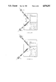
- FIG. 3A is a plan view of the continuous fibre optic liquid level sensor embodiment of the invention.
- FIG. 3B is a perspective view of the embodiment of FIG. 3A
- FIG. 4 describes the principle of operation of the fluorescent detector optical fibre shown in FIG. 3;
- FIG. 5 shows the cases of total internal reflection and refraction in the presence of air and liquid respectively for the embodiment of the invention depicted in FIG. 3;
- FIGS. 6, 7 and 8 show additional embodiments of the present invention.
- a source optical fibre 1 is optically coupled to a light source 5 such as a light emitting diode or laser diode and a detector optical fibre 2 is optically coupled to a light detector 6 such as a photodiode or phototransistor.
- the fibres 1 and 2 are mounted in an optically transparent substrate 3 in the same plane normal to the planar interface surface 4 and at an equal angle ⁇ to the normal such that the angle of incidence equals the angle of reflection.
- the optical fibre ends may be polished using standard lapping film techniques or may be simply cleaved or cut, and mounted in blind holes in which some fluid or epoxy, of a refractive index which matches that of the optical fibre core material and the substrate material, has been placed to minimize any optical loss due to refractive index mismatch, i.e. Fresnel loss.
- the blind end of each hole is normally as close to the interface surface 4 a possible to minimize the optical loss of the effectively unguided light due to the effective end separation of the optical fibres.
- the critical angles for total internal reflection are 41.8 degrees and 62.5 degrees for air and water respectively.
- the optical fibres are positioned between these two critical angles, e.g. at 45 degrees with respect to the normal and in the same plane such that the angle of incidence of the light exiting the source optical fibre onto the window to liquid interface equals the angle of reflection and of the detector optical fibre, then in the presence of air, total internal reflection will occur and the light detector 6 will be illuminated signifying an "on" or low level condition (FIG. 2A).
- the light exiting the source fibre will be largely refracted into the liquid and the light detector 6 will be dark, indicating an "off" or high level condition (FIG. 2B).
- a multiplicity of such point detectors can be ganged together to approximate continuous level detection.
- a truly continuous liquid level sensor can be fabricated with a somewhat different optical fibre arrangement based on the same optical principle and a similar packaging arrangement.
- the source optical fibre 14 and the detector optical fibre 13 are embedded longitudinally in the optically transparent substrate material 7.
- the two optical fibres are parallel or nearly parallel to one another and to the planar sensor window 17.
- a radius from each of the two fibres intersects at or near the sensor window 17 according to the basic laws of reflection.
- the core 8 of the detector optical fibre 13 is doped with a fluorescent substance which when irradiated or excited with a short wavelength optical source, re-emits light of a longer wavelength.
- the source fibre 14 is optically connected at one or both ends to an external light source 15 which may be a laser diode or flash tube such as a xenon strobe light, either of which has some wavelength or colour component matched to the fluorescence excitation.
- the source fibre is configured so that light is lost or emitted along its length, thus creating an optical line source. This can be achieved by having the fibre abraded or scratched or modified to include a longitudinal strip of higher refractive index than that of the core. Another means of "leaking" the light from the fibre is to arrange it in a series of microbends.
- the light source fibre 14 illuminates the fluorescent detector optical fibre 13 via total internal reflection as in the previous embodiment, the incident light being proportional to the length of the sensor face which is exposed to the air as shown in FIG. 5.
- This incident light stimulates a proportional fluorescence signal in the detector optical fibre which is then guided to the external light detector.
- the light from the line source optical fibre emitted below the liquid's level is refracted into the liquid and does not propagate to the fluorescent fibre where it would contribute to the fluorescence signal.
- the resulting optical signal received at the light detector corresponds inversely with the liquid level.
- the lenses 12 as shown in FIGS. 3A and 3B are convex or cylindrical positive, which is suitable for the case where the refractive index of the lens is greater than that of the medium. If the reverse were true the lenses would be concave or cylindrical negative.
- a light signal offset will always be present at the light detector which can be used to indicate the integrity of the optical link from and including the light source to the light detector. Any failure in this link will be instantly detectable thus providing a self checking feature. Placement of the reflector 18 at the base of the assembly permits it to monitor the integrity of the sensor as well a that of the optical link.
- Performance of the sensor assembly in FIG. 5 can be improved by constructing the substrate 17 in a series of horizontal slices or laminates 19 coated with an opaque material 20 as seen in FIG. 6.
- the result is alternating layers of clear and opaque material such that only light rays propagating near the horizontal direction are allowed to travel to the detector fibre, giving enhanced accuracy of level detection.
- Another improvement is the addition of a vertically mounted spacer 21 of opaque material placed between the source 14 and detector 13 fibres in order to prevent direct propagation of light between them. Hence the only light that propagates to the detector is that which has been reflected from the window 17 (see FIG. 7).
- the sensor can be made to measure parameters other than liquid level. If the vertical spacer 21 described above is allowed to slide vertically in response to an externally applied force, the light output signal will be analogous to the amplitude of the force o displacement. Parameters such as temperature and pressure could be measured by causing the motion of the slide in response to the deflection of a bimetallic element or diaphragm.
- the relative positions of the source and detector fibres could be arranged such as to give a stronger signal (e.g. fibres closer together) in parts of the tank having larger surface area and hence representing greater liquid quantity.
- a stepwise or "digital" output could be achieved by replacing the detector fibre 13 with a fibre made up of a series of fluorescent fibre segments 22 joined by non-fluorescent fibre segments 23 as shown in FIG. 8. Such an arrangement would be tolerant to signal variations imposed by varying environmental conditions, as the presence of a signal within a certain range would be known to indicate a specific level.
- a stepwise output could also be achieved by retaining the fluorescent detector fibre but replacing the continuous source fibre with a series of fibres of different lengths (one terminating at each "step”). The fibres could share a common optical source. The output would give a "count" of the number of source fibres exposed and hence indicate the liquid level. Either of these step-output arrangements could be arranged non-linearly to provide liquid quantity measurement (as opposed to level) in irregularly shaped tanks as described above.
Abstract
Description
Claims (12)
Priority Applications (4)
| Application Number | Priority Date | Filing Date | Title |
|---|---|---|---|
| US07/168,481 US4870292A (en) | 1988-03-15 | 1988-03-15 | Fibre optic sensor for liquid level and other parameters |
| CA 593572 CA1332205C (en) | 1988-03-15 | 1989-03-14 | Fibre optic sensors for the continuous measurement of liquid level and other parameters |
| EP19890302507 EP0334533B1 (en) | 1988-03-15 | 1989-03-14 | Fibre optic discrete or continuous liquid level sensor |
| DE1989603183 DE68903183T2 (en) | 1988-03-15 | 1989-03-14 | FIBER OPTICAL LEVEL SENSOR FOR DISCRETE OR CONTINUOUS DISPLAY OF A LIQUID LEVEL. |
Applications Claiming Priority (1)
| Application Number | Priority Date | Filing Date | Title |
|---|---|---|---|
| US07/168,481 US4870292A (en) | 1988-03-15 | 1988-03-15 | Fibre optic sensor for liquid level and other parameters |
Publications (1)
| Publication Number | Publication Date |
|---|---|
| US4870292A true US4870292A (en) | 1989-09-26 |
Family
ID=22611658
Family Applications (1)
| Application Number | Title | Priority Date | Filing Date |
|---|---|---|---|
| US07/168,481 Expired - Fee Related US4870292A (en) | 1988-03-15 | 1988-03-15 | Fibre optic sensor for liquid level and other parameters |
Country Status (1)
| Country | Link |
|---|---|
| US (1) | US4870292A (en) |
Cited By (36)
| Publication number | Priority date | Publication date | Assignee | Title |
|---|---|---|---|---|
| US4994682A (en) * | 1989-05-19 | 1991-02-19 | Focal Technologies Incorporated | Fiber optic continuous liquid level sensor |
| US5164605A (en) * | 1991-08-14 | 1992-11-17 | The Babcock & Wilcox Company | Fiber optic displacement sensor using fiber optic coil |
| US5425624A (en) * | 1993-10-22 | 1995-06-20 | Itt Corporation | Optical fluid-level switch and controls for bilge pump apparatus |
| US5561732A (en) * | 1991-09-09 | 1996-10-01 | Coventry Univ. Enterprises & Welmed Ltd. | Data transmission |
| EP0823627A1 (en) * | 1996-08-09 | 1998-02-11 | Siemens-Elema AB | Device for identifying liquid anaesthetics |
| US5785100A (en) * | 1997-02-14 | 1998-07-28 | Vickers, Incorporated | Liquid level detection system |
| US6079433A (en) * | 1997-09-12 | 2000-06-27 | The Toro Company | Automatic soil moisture sensing and watering system |
| US6172377B1 (en) * | 1998-10-28 | 2001-01-09 | Sandia Corporation | Fluorescent optical liquid level sensor |
| US6173609B1 (en) * | 1997-06-20 | 2001-01-16 | Optical Sensor Consultants, Inc. | Optical level sensor |
| US6333512B1 (en) | 1998-07-15 | 2001-12-25 | Alvin R. Wirthlin | Optical gauge for determining the level of a medium in a container |
| US6358748B1 (en) * | 2000-09-28 | 2002-03-19 | The United States Of America As Represented By The U.S. Department Of Energy | Microbend fiber-optic chemical sensor |
| US6612169B1 (en) * | 2001-05-10 | 2003-09-02 | Ford Global Technologies, Llc | Apparatus for engine lubricant level detection |
| US6693285B1 (en) | 2002-03-20 | 2004-02-17 | Sandia Corporation | Fluorescent fluid interface position sensor |
| US20040119037A1 (en) * | 2002-07-16 | 2004-06-24 | Mentzer Mark A. | Electro-optic fluid quantity measurement system |
| US6965709B1 (en) | 2003-05-14 | 2005-11-15 | Sandia Corporation | Fluorescent optical position sensor |
| US20060006353A1 (en) * | 2004-07-07 | 2006-01-12 | Wirthlin Alvin R | Optical transducer for continuously determining liquid level |
| US20070048157A1 (en) * | 2005-08-24 | 2007-03-01 | Johnson Pumps Of America Inc. | Submersible pump with integrated liquid level sensing and control system |
| US20070263955A1 (en) * | 2006-05-11 | 2007-11-15 | Keen Jeffrey | Method and apparatus for improving accuracy of optic sensors used in capillary tube instruments |
| US7305875B1 (en) | 2005-03-31 | 2007-12-11 | Gerald Pindus | Method and apparatus for measuring the volume of fuel in a tank |
| US7329857B1 (en) | 2006-03-01 | 2008-02-12 | Sandia Corporation | Side-emitting fiber optic position sensor |
| US20090051905A1 (en) * | 2004-12-23 | 2009-02-26 | Baker Hughes Incorporated | Optical Inclination Sensor |
| US20110056290A1 (en) * | 2009-09-08 | 2011-03-10 | Jadak, Llc | System and method for detection of liquid level in a vessel |
| US20120279987A1 (en) * | 2011-05-06 | 2012-11-08 | Gotohti.Com Inc. | Fluid Level Gauge |
| US8362436B1 (en) | 2006-03-14 | 2013-01-29 | Advanced Precision Inc. | Electro-optic fluid quantity measurement system |
| DE102011089703B3 (en) * | 2011-12-22 | 2013-05-23 | Continental Automotive Gmbh | Optical measuring arrangement for determination of e.g. light speed within diesel fuel in motor car, has light sources whose light is incident at certain angle different from another angle and reflected to light sensors |
| US20140096642A1 (en) * | 2012-10-05 | 2014-04-10 | Remy Technologies, Llc | Starter motor |
| US20140102307A1 (en) * | 2012-10-15 | 2014-04-17 | Melitta Europa GmbH & Co.KG. | Water tank for a household device and a household device |
| US9541445B2 (en) | 2015-04-07 | 2017-01-10 | Xerox Corporation | Optical level sensor for reflective liquids |
| US9645004B2 (en) | 2014-11-19 | 2017-05-09 | The Boeing Company | Optical impedance modulation for fuel quantity measurement comprising a fiber encased by a tube having a longitudinal slot with a lens |
| US10175087B2 (en) | 2017-02-09 | 2019-01-08 | The Boeing Company | Fuel level sensor having dual fluorescent plastic optical fibers |
| US10352755B2 (en) | 2017-04-17 | 2019-07-16 | The Boeing Company | Passive differential liquid level sensor using optical fibers |
| US10371559B2 (en) | 2017-04-17 | 2019-08-06 | The Boeing Company | Differential spectral liquid level sensor |
| US10809192B2 (en) * | 2016-12-28 | 2020-10-20 | Vito Nv | Optical methods for phase change materials |
| US10935413B2 (en) | 2019-04-10 | 2021-03-02 | The Boeing Company | Non-contact time-of-flight fuel level sensor using plastic optical fiber |
| US11161110B2 (en) | 2018-08-24 | 2021-11-02 | International Business Machines Corporation | MEMS optical liquid level sensor |
| US11326927B2 (en) * | 2017-02-10 | 2022-05-10 | Safran Electrical & Power | Optical probe for measuring the level of a liquid in a tank |
Citations (13)
| Publication number | Priority date | Publication date | Assignee | Title |
|---|---|---|---|---|
| CA913927A (en) * | 1972-11-07 | Moriguti Kazuo | Method and apparatus for photoelectrically detecting a liquid level | |
| US3995168A (en) * | 1975-08-04 | 1976-11-30 | Grumman Aerospace Corporation | Electro optical fluid measurement system |
| US4119860A (en) * | 1976-01-08 | 1978-10-10 | Cornelius Leonard Gooley | Fluid measurement |
| CA1087269A (en) * | 1976-09-03 | 1980-10-07 | William F. Jacobsen | Frequency sensitive level detecting apparatus |
| US4246489A (en) * | 1979-04-16 | 1981-01-20 | Tokyo Shibaura Electric Co., Ltd. | Liquid level detector for detecting a liquid level when reaching a prescribed height |
| CA1102151A (en) * | 1977-07-01 | 1981-06-02 | Alan L. Harmer | Optical gauge |
| CA1115084A (en) * | 1977-11-23 | 1981-12-29 | Jan Bergstrom | Optical measuring device using optical fibers |
| US4354180A (en) * | 1980-12-19 | 1982-10-12 | Genelco, Inc. | Electro-optical liquid level sensor |
| CA1154117A (en) * | 1978-06-12 | 1983-09-20 | Masaya Tanaka | Liquid leakage detection system |
| US4440022A (en) * | 1981-10-14 | 1984-04-03 | Smiths Industries Public Limited Company | Liquid-level detection |
| CA1190762A (en) * | 1981-12-30 | 1985-07-23 | Nigel A. Heard | Fibre optic level gauge and valve head provided with a fibre optic level gauge, for pressure vessels |
| US4727247A (en) * | 1985-12-20 | 1988-02-23 | Rosemount Limited | Light attenuation sensing apparatus for measuring physical parameters and other variables utilizing a light conducting member containing a fluorescent material |
| US4788444A (en) * | 1985-12-18 | 1988-11-29 | Lucas Electrical Electronics And Systems Limited | Liquid level detection |
-
1988
- 1988-03-15 US US07/168,481 patent/US4870292A/en not_active Expired - Fee Related
Patent Citations (13)
| Publication number | Priority date | Publication date | Assignee | Title |
|---|---|---|---|---|
| CA913927A (en) * | 1972-11-07 | Moriguti Kazuo | Method and apparatus for photoelectrically detecting a liquid level | |
| US3995168A (en) * | 1975-08-04 | 1976-11-30 | Grumman Aerospace Corporation | Electro optical fluid measurement system |
| US4119860A (en) * | 1976-01-08 | 1978-10-10 | Cornelius Leonard Gooley | Fluid measurement |
| CA1087269A (en) * | 1976-09-03 | 1980-10-07 | William F. Jacobsen | Frequency sensitive level detecting apparatus |
| CA1102151A (en) * | 1977-07-01 | 1981-06-02 | Alan L. Harmer | Optical gauge |
| CA1115084A (en) * | 1977-11-23 | 1981-12-29 | Jan Bergstrom | Optical measuring device using optical fibers |
| CA1154117A (en) * | 1978-06-12 | 1983-09-20 | Masaya Tanaka | Liquid leakage detection system |
| US4246489A (en) * | 1979-04-16 | 1981-01-20 | Tokyo Shibaura Electric Co., Ltd. | Liquid level detector for detecting a liquid level when reaching a prescribed height |
| US4354180A (en) * | 1980-12-19 | 1982-10-12 | Genelco, Inc. | Electro-optical liquid level sensor |
| US4440022A (en) * | 1981-10-14 | 1984-04-03 | Smiths Industries Public Limited Company | Liquid-level detection |
| CA1190762A (en) * | 1981-12-30 | 1985-07-23 | Nigel A. Heard | Fibre optic level gauge and valve head provided with a fibre optic level gauge, for pressure vessels |
| US4788444A (en) * | 1985-12-18 | 1988-11-29 | Lucas Electrical Electronics And Systems Limited | Liquid level detection |
| US4727247A (en) * | 1985-12-20 | 1988-02-23 | Rosemount Limited | Light attenuation sensing apparatus for measuring physical parameters and other variables utilizing a light conducting member containing a fluorescent material |
Non-Patent Citations (6)
| Title |
|---|
| "Innovations", Oct., 1987, vol. 2, No. 1, pp. 6-7. |
| Belkerdid et al.; "Fiber Optic Fluid Level Sensor", SPIE vol. 566, Fiber Optic and Laser Sensors III (1985), pp. 153-158. |
| Belkerdid et al.; Fiber Optic Fluid Level Sensor , SPIE vol. 566, Fiber Optic and Laser Sensors III (1985), pp. 153 158. * |
| Innovations , Oct., 1987, vol. 2, No. 1, pp. 6 7. * |
| K. Spenner et al.; "Experimental Investigations on Fiber Optic Liquid Level Sensors and Refractometers"; pp. 96-99. |
| K. Spenner et al.; Experimental Investigations on Fiber Optic Liquid Level Sensors and Refractometers ; pp. 96 99. * |
Cited By (47)
| Publication number | Priority date | Publication date | Assignee | Title |
|---|---|---|---|---|
| US4994682A (en) * | 1989-05-19 | 1991-02-19 | Focal Technologies Incorporated | Fiber optic continuous liquid level sensor |
| US5164605A (en) * | 1991-08-14 | 1992-11-17 | The Babcock & Wilcox Company | Fiber optic displacement sensor using fiber optic coil |
| US5561732A (en) * | 1991-09-09 | 1996-10-01 | Coventry Univ. Enterprises & Welmed Ltd. | Data transmission |
| US5425624A (en) * | 1993-10-22 | 1995-06-20 | Itt Corporation | Optical fluid-level switch and controls for bilge pump apparatus |
| EP0823627A1 (en) * | 1996-08-09 | 1998-02-11 | Siemens-Elema AB | Device for identifying liquid anaesthetics |
| US6422073B1 (en) | 1996-08-09 | 2002-07-23 | Siemens Elema Ab | Device for identifying liquid anaesthetics |
| US5785100A (en) * | 1997-02-14 | 1998-07-28 | Vickers, Incorporated | Liquid level detection system |
| US6173609B1 (en) * | 1997-06-20 | 2001-01-16 | Optical Sensor Consultants, Inc. | Optical level sensor |
| US6079433A (en) * | 1997-09-12 | 2000-06-27 | The Toro Company | Automatic soil moisture sensing and watering system |
| US6333512B1 (en) | 1998-07-15 | 2001-12-25 | Alvin R. Wirthlin | Optical gauge for determining the level of a medium in a container |
| US6172377B1 (en) * | 1998-10-28 | 2001-01-09 | Sandia Corporation | Fluorescent optical liquid level sensor |
| US6358748B1 (en) * | 2000-09-28 | 2002-03-19 | The United States Of America As Represented By The U.S. Department Of Energy | Microbend fiber-optic chemical sensor |
| US6612169B1 (en) * | 2001-05-10 | 2003-09-02 | Ford Global Technologies, Llc | Apparatus for engine lubricant level detection |
| US6693285B1 (en) | 2002-03-20 | 2004-02-17 | Sandia Corporation | Fluorescent fluid interface position sensor |
| US20040119037A1 (en) * | 2002-07-16 | 2004-06-24 | Mentzer Mark A. | Electro-optic fluid quantity measurement system |
| US6831290B2 (en) | 2002-07-16 | 2004-12-14 | Strube, Inc. | Electro-optic fluid quantity measurement system |
| US6965709B1 (en) | 2003-05-14 | 2005-11-15 | Sandia Corporation | Fluorescent optical position sensor |
| US20060006353A1 (en) * | 2004-07-07 | 2006-01-12 | Wirthlin Alvin R | Optical transducer for continuously determining liquid level |
| US7161165B2 (en) | 2004-07-07 | 2007-01-09 | Opti Sensor Systems, Llc | Optical transducer for continuously determining liquid level |
| US7719690B2 (en) * | 2004-12-23 | 2010-05-18 | Baker Hughes Incorporated | Optical inclination sensor |
| US20090051905A1 (en) * | 2004-12-23 | 2009-02-26 | Baker Hughes Incorporated | Optical Inclination Sensor |
| US7305875B1 (en) | 2005-03-31 | 2007-12-11 | Gerald Pindus | Method and apparatus for measuring the volume of fuel in a tank |
| US20070048157A1 (en) * | 2005-08-24 | 2007-03-01 | Johnson Pumps Of America Inc. | Submersible pump with integrated liquid level sensing and control system |
| US7625187B2 (en) * | 2005-08-24 | 2009-12-01 | Johnson Pumps Of America Inc. | Submersible pump with integrated liquid level sensing and control system |
| US7329857B1 (en) | 2006-03-01 | 2008-02-12 | Sandia Corporation | Side-emitting fiber optic position sensor |
| US8362436B1 (en) | 2006-03-14 | 2013-01-29 | Advanced Precision Inc. | Electro-optic fluid quantity measurement system |
| US20070263955A1 (en) * | 2006-05-11 | 2007-11-15 | Keen Jeffrey | Method and apparatus for improving accuracy of optic sensors used in capillary tube instruments |
| US20110056290A1 (en) * | 2009-09-08 | 2011-03-10 | Jadak, Llc | System and method for detection of liquid level in a vessel |
| US7982201B2 (en) | 2009-09-08 | 2011-07-19 | Jadak, Llc | System and method for detection of liquid level in a vessel |
| US20120279987A1 (en) * | 2011-05-06 | 2012-11-08 | Gotohti.Com Inc. | Fluid Level Gauge |
| US20140144934A1 (en) * | 2011-05-06 | 2014-05-29 | Gotohti.Com Inc. | Fluid Level Gauge |
| US9027788B2 (en) * | 2011-05-06 | 2015-05-12 | Gotohti.Com Inc. | Fluid level gauge |
| DE102011089703B3 (en) * | 2011-12-22 | 2013-05-23 | Continental Automotive Gmbh | Optical measuring arrangement for determination of e.g. light speed within diesel fuel in motor car, has light sources whose light is incident at certain angle different from another angle and reflected to light sensors |
| US20140096642A1 (en) * | 2012-10-05 | 2014-04-10 | Remy Technologies, Llc | Starter motor |
| US20140102307A1 (en) * | 2012-10-15 | 2014-04-17 | Melitta Europa GmbH & Co.KG. | Water tank for a household device and a household device |
| US9645004B2 (en) | 2014-11-19 | 2017-05-09 | The Boeing Company | Optical impedance modulation for fuel quantity measurement comprising a fiber encased by a tube having a longitudinal slot with a lens |
| US9541445B2 (en) | 2015-04-07 | 2017-01-10 | Xerox Corporation | Optical level sensor for reflective liquids |
| US10809192B2 (en) * | 2016-12-28 | 2020-10-20 | Vito Nv | Optical methods for phase change materials |
| US10175087B2 (en) | 2017-02-09 | 2019-01-08 | The Boeing Company | Fuel level sensor having dual fluorescent plastic optical fibers |
| US10451469B2 (en) | 2017-02-09 | 2019-10-22 | The Boeing Company | Fuel level sensor having dual fluorescent plastic optical fibers |
| US11326927B2 (en) * | 2017-02-10 | 2022-05-10 | Safran Electrical & Power | Optical probe for measuring the level of a liquid in a tank |
| US10352755B2 (en) | 2017-04-17 | 2019-07-16 | The Boeing Company | Passive differential liquid level sensor using optical fibers |
| US10371559B2 (en) | 2017-04-17 | 2019-08-06 | The Boeing Company | Differential spectral liquid level sensor |
| US20190293473A1 (en) * | 2017-04-17 | 2019-09-26 | The Boeing Company | Differential Spectral Liquid Level Sensor |
| US10845231B2 (en) * | 2017-04-17 | 2020-11-24 | The Boeing Company | Differential spectral liquid level sensor |
| US11161110B2 (en) | 2018-08-24 | 2021-11-02 | International Business Machines Corporation | MEMS optical liquid level sensor |
| US10935413B2 (en) | 2019-04-10 | 2021-03-02 | The Boeing Company | Non-contact time-of-flight fuel level sensor using plastic optical fiber |
Similar Documents
| Publication | Publication Date | Title |
|---|---|---|
| US4870292A (en) | Fibre optic sensor for liquid level and other parameters | |
| US4994682A (en) | Fiber optic continuous liquid level sensor | |
| US4942306A (en) | Fibre optic sensor for the continuous measurement liquids level and other parameters | |
| EP0334533B1 (en) | Fibre optic discrete or continuous liquid level sensor | |
| US4745293A (en) | Method and apparatus for optically measuring fluid levels | |
| EP0262670B1 (en) | Fiber optic fluid sensors | |
| US6172377B1 (en) | Fluorescent optical liquid level sensor | |
| US5712934A (en) | Fiber optic infrared sensor | |
| US5044723A (en) | Tapered fibre sensor | |
| US5399876A (en) | Optical point level sensor with lens | |
| EP0027099A1 (en) | Refractive-index responsive light-signal system | |
| US5422495A (en) | Optical sensor having a floatation means for detecting fluids through refractive index measurement | |
| US5946084A (en) | Hemispherical double reflection optical sensor | |
| US4678902A (en) | Fiber optic transducers with improved sensitivity | |
| US6801678B2 (en) | Fiber optic level detector | |
| EP0453226A2 (en) | Fiber optic liquid leak detector | |
| KR940003737B1 (en) | Fibre optic liquid level gauge | |
| US7062125B2 (en) | Prismatic reflection optical waveguide device | |
| US4624570A (en) | Fiber optic displacement sensor | |
| US6693285B1 (en) | Fluorescent fluid interface position sensor | |
| EP2431730B1 (en) | Device for discriminating between different fluids based on their refractive index | |
| US6795598B1 (en) | Liquid-level sensor having multiple solid optical conductors with surface discontinuities | |
| US5446278A (en) | Fiber optic sensor employing successively destroyed coupled points or reflectors for detecting shock wave speed and damage location | |
| GB2076960A (en) | Liquid sensor | |
| US6728430B1 (en) | Fluid identification system |
Legal Events
| Date | Code | Title | Description |
|---|---|---|---|
| AS | Assignment |
Owner name: FOCAL MARINE LIMITED, 1378 BEDFORD HIGHWAY, BEDFOR Free format text: ASSIGNMENT OF ASSIGNORS INTEREST.;ASSIGNORS:ALPERT, MARTIN D.;SNOW, JAMES W.;REEL/FRAME:004848/0855;SIGNING DATES FROM 19880302 TO 19880303 Owner name: FOCAL MARINE LIMITED,CANADA Free format text: ASSIGNMENT OF ASSIGNORS INTEREST;ASSIGNORS:ALPERT, MARTIN D.;SNOW, JAMES W.;SIGNING DATES FROM 19880302 TO 19880303;REEL/FRAME:004848/0855 |
|
| AS | Assignment |
Owner name: FOCAL TECHNOLOGIES INCORPORATED, CANADA Free format text: ASSIGNMENT OF A PART OF ASSIGNORS INTEREST;ASSIGNOR:FOCAL MARINE LIMITED;REEL/FRAME:005185/0121 Effective date: 19880510 |
|
| AS | Assignment |
Owner name: IMO INDUSTRIES INC. Free format text: ASSIGNMENT OF ASSIGNORS INTEREST.;ASSIGNOR:FOCAL TECHNOLOGIES INCORPORATED;REEL/FRAME:005996/0770 Effective date: 19920117 Owner name: IMO INDUSTRIES INC., NEW JERSEY Free format text: ASSIGNMENT OF ASSIGNORS INTEREST;ASSIGNOR:FOCAL TECHNOLOGIES INCORPORATED;REEL/FRAME:005996/0770 Effective date: 19920117 |
|
| FEPP | Fee payment procedure |
Free format text: PAT HLDR NO LONGER CLAIMS SMALL ENT STAT AS SMALL BUSINESS (ORIGINAL EVENT CODE: LSM2); ENTITY STATUS OF PATENT OWNER: LARGE ENTITY Free format text: PAYOR NUMBER ASSIGNED (ORIGINAL EVENT CODE: ASPN); ENTITY STATUS OF PATENT OWNER: LARGE ENTITY |
|
| FPAY | Fee payment |
Year of fee payment: 4 |
|
| AS | Assignment |
Owner name: BANKERS TRUST COMPANY Free format text: SECURITY INTEREST;ASSIGNORS:IMO INDUSTRIES INC.;INCOM TRANSPORTATION INC.;OPTIC - ELECTRONIC INTERNATIONAL, INC.;AND OTHERS;REEL/FRAME:006629/0884 Effective date: 19930715 |
|
| AS | Assignment |
Owner name: CITIBANK, N.A., NEW YORK Free format text: SECURITY INTEREST;ASSIGNOR:IMO INDUSTRIES INC.;REEL/FRAME:007119/0942 Effective date: 19940819 |
|
| AS | Assignment |
Owner name: IMO INDUSTRIES, INC., NEW JERSEY Free format text: RELEASE OF PATENTS;ASSIGNOR:BANKERS TRUST COMPANY;REEL/FRAME:007927/0884 Effective date: 19960507 |
|
| AS | Assignment |
Owner name: CITICORP USA, INC, NEW YORK Free format text: SECURITY INTEREST;ASSIGNOR:IMO INDUSTRIAL INC.;REEL/FRAME:008133/0667 Effective date: 19960429 |
|
| AS | Assignment |
Owner name: IMO INDUSTRIES, INC., NEW JERSEY Free format text: RELEASE AND REASSIGNMENT;ASSIGNOR:CITIBANK, N.A.;REEL/FRAME:008261/0049 Effective date: 19960429 |
|
| REMI | Maintenance fee reminder mailed | ||
| AS | Assignment |
Owner name: WARREN PUMPS INC., MASSACHUSETTS Free format text: RELEASE AND REASSIGNMENT;ASSIGNOR:CITICORP USA, INC.;REEL/FRAME:008693/0101 Effective date: 19970829 Owner name: VHC INC., FORMERLY KNOWN AS VARO INC., NEW JERSEY Free format text: RELEASE AND REASSIGNMENT;ASSIGNOR:CITICORP USA, INC.;REEL/FRAME:008693/0101 Effective date: 19970829 Owner name: IMO INDUSTRIES INC., NEW JERSEY Free format text: RELEASE AND REASSIGNMENT;ASSIGNOR:CITICORP USA, INC.;REEL/FRAME:008693/0101 Effective date: 19970829 |
|
| LAPS | Lapse for failure to pay maintenance fees | ||
| FP | Lapsed due to failure to pay maintenance fee |
Effective date: 19971001 |
|
| AS | Assignment |
Owner name: GEMS SENSORS INC., A CORP. OF DELAWARE, CONNECTICU Free format text: ASSIGNMENT OF ASSIGNORS INTEREST;ASSIGNOR:IMO INDUSTRIES, INC., A CORP. OF DELAWARE;REEL/FRAME:008842/0822 Effective date: 19970829 |
|
| AS | Assignment |
Owner name: INDUSTRIAL SENSORS, INC., DELAWARE Free format text: ASSIGNMENT OF ASSIGNORS INTEREST;ASSIGNORS:RELAY PARK REALISATIONS LIMITED (RPR);GEMS SENSORS INC. (GEMS);REEL/FRAME:009737/0805 Effective date: 19980619 |
|
| AS | Assignment |
Owner name: INDUSTRIAL SENSORS, INC., DELAWARE Free format text: CORRECTION OF ASSIGNMENT TO DELETE THE ASSIGNOR (RELAY PARK REALISATIONS LIMITED) FROM A DOCUMENT PREVIOUSLY RECORDED AT REEL 9737, FRAME 0805.;ASSIGNOR:GEMS SENSORS INC.;REEL/FRAME:010255/0704 Effective date: 19990618 |
|
| STCH | Information on status: patent discontinuation |
Free format text: PATENT EXPIRED DUE TO NONPAYMENT OF MAINTENANCE FEES UNDER 37 CFR 1.362 |