US4869686A - Right angle electrical connector - Google Patents
Right angle electrical connector Download PDFInfo
- Publication number
- US4869686A US4869686A US07/175,015 US17501588A US4869686A US 4869686 A US4869686 A US 4869686A US 17501588 A US17501588 A US 17501588A US 4869686 A US4869686 A US 4869686A
- Authority
- US
- United States
- Prior art keywords
- shell
- eyelet
- cable
- peripheral side
- side wall
- Prior art date
- Legal status (The legal status is an assumption and is not a legal conclusion. Google has not performed a legal analysis and makes no representation as to the accuracy of the status listed.)
- Expired - Lifetime
Links
Images

Classifications
-
- H—ELECTRICITY
- H01—ELECTRIC ELEMENTS
- H01R—ELECTRICALLY-CONDUCTIVE CONNECTIONS; STRUCTURAL ASSOCIATIONS OF A PLURALITY OF MUTUALLY-INSULATED ELECTRICAL CONNECTING ELEMENTS; COUPLING DEVICES; CURRENT COLLECTORS
- H01R13/00—Details of coupling devices of the kinds covered by groups H01R12/70 or H01R24/00 - H01R33/00
- H01R13/58—Means for relieving strain on wire connection, e.g. cord grip, for avoiding loosening of connections between wires and terminals within a coupling device terminating a cable
- H01R13/5804—Means for relieving strain on wire connection, e.g. cord grip, for avoiding loosening of connections between wires and terminals within a coupling device terminating a cable comprising a separate cable clamping part
- H01R13/5808—Means for relieving strain on wire connection, e.g. cord grip, for avoiding loosening of connections between wires and terminals within a coupling device terminating a cable comprising a separate cable clamping part formed by a metallic element crimped around the cable
-
- H—ELECTRICITY
- H01—ELECTRIC ELEMENTS
- H01R—ELECTRICALLY-CONDUCTIVE CONNECTIONS; STRUCTURAL ASSOCIATIONS OF A PLURALITY OF MUTUALLY-INSULATED ELECTRICAL CONNECTING ELEMENTS; COUPLING DEVICES; CURRENT COLLECTORS
- H01R13/00—Details of coupling devices of the kinds covered by groups H01R12/70 or H01R24/00 - H01R33/00
- H01R13/46—Bases; Cases
- H01R13/52—Dustproof, splashproof, drip-proof, waterproof, or flameproof cases
Definitions
- electrical connectors enable the conductors of a cable to be electrically joined to terminals in the connector.
- the connector with the cable extending therefrom can be mated with a compatible connector which is mounted to another cable, an electrical apparatus or the like.
- Electrical connectors desirably should achieve many objectives including: a high quality electrical connection; low manufacturing costs; a minimum number of components; a low design profile; easy assembly; environmental sealing; compatibility with other connectors and durability.
- Still another structure for obtaining the right angle orientation of the connector is to employ multiple metallic parts that are brazed together. Once again, the resulting parts are reliable, but they are costly and labor intensive to manufacture, and are undesirably large.
- a further object of the subject invention is to provide an efficient electrical connector with a right angle cable exit and with a compact design profile.
- the subject invention is directed to a right angle connector plug or socket that can be manufactured inexpensively, assembled easily from a small number of components, while still providing environmental sealing, a low design profile and desirable strain relief.
- the connector comprises a substantially rigid housing having first and second telescopingly engageable shells. Each shell comprises opposed first and second ends and a generally tubular peripheral side wall extending therebetween.
- the first shell comprises a cable crimping cutout portion extending through the peripheral side wall adjacent one end thereof.
- the second shell includes a cable receiving aperture extending through the peripheral side wall intermediate the opposed ends.
- the second shell may include a flared entry semi-elliptical cutout or slot in the peripheral side wall extending inwardly from an end to a point intermediate the opposed ends.
- the first or second shell is dimensioned and configured to receive at least one terminal connectable to a conductor of a cable.
- the cable extends from the terminal and through the aperture or cutout in the peripheral side wall of the second shell. The telescoping engagement of the shells will cause the cable crimping cutout portion of the first shell to positively retain the cable at the aperture or cutout in the second shell.
- the connector housing may further comprise a crimpable eyelet disposed over the cable and extending through the aperture or cutout in the second shell.
- the telescoping engagement of the shells will cause the cutout portion of the first shell to crimp the eyelet.
- the deformed eyelet will positively engage both the cable and the second shell adjacent the aperture therethrough.
- the connector may comprise a dielectric insert for supporting the terminals of the connector.
- the dielectric insert may be of unitary construction and may be molded from an elastomeric material having a high coefficient of friction, such as the polyester elastomers described and identified in application Ser. No. 005,045.
- the terminals mountable in the insert are mechanically and electrically connected to the conductors of the cable.
- the connector comprises a rigid first shell with opposed forward and rear ends.
- the first shell preferably is formed from a metallic material such as brass.
- the forward end of the first shell has its interior dimensioned and configured to receive at least a portion of the dielectric insert.
- the forward end of the first shell is dimensioned to frictionally retain the elastomeric insert therein.
- a coupling nut may be mounted over the forward end of the first shell and suitably retained thereon.
- a portion of the forward end of the first shell may be flared outwardly to engage a portion of the coupling nut and to permit relative rotation therebetween.
- the rear end of the first shell also is of generally tubular configuration, and may be substantially cylindrical. However, a peripheral portion of the rear end of the first shell includes the above described cutout portion. The cutout portion of the rear end of the first shell may be arcuate in configuration.
- the second shell may have an opened forward portion and a closed rear end.
- the forward portion of the second shell may have a size and configuration that enables the second shell to be telescopingly engaged with the rear end of the first shell and to be tightly retained in the assembled condition.
- the second shell is further defined by an aperture extending through a peripheral wall intermediate the opposed front and rear ends thereof.
- the connector may further comprise an eyelet of generally tubular configuration and having an internal dimension to enable the eyelet to be tightly received over the cable.
- the external dimension of the eyelet enables the eyelet with the cable mounted therein to be inserted through the aperture in the peripheral side wall of the second shell.
- the external dimensions of the eyelet and the dimensions of the cutout portion in the first shell are selected to enable the cutout portion to engage and at least partly surround the eyelet.
- the connector of the subject invention may be assembled by electrically and mechanically connecting the conductors of the cable to the respective terminals.
- the terminals in turn may be engaged in the apertures of the dielectric insert.
- the coupling nut may be engaged with the forward end of the first shell and the cable may be urged longitudinally through the first shell such that the insert with the terminals therein is securely engaged within the first shell.
- the cable also may be directed through the aperture in the second shell and through the eyelet. It is to be understood, however, that the particular order of the above identified assembly steps may vary considerably depending upon the particular application for the connector and depending upon the specific construction for the terminals, the dielectric insert, the forward end of the first shell and such.
- the assembly of the connector may be completed by advancing the eyelet and the assembled first shell toward one another with the second shell therebetween. More particularly, the eyelet with the cable directed therethrough may be urged into the peripheral side wall aperture in the second shell, while the second shell is urged into telescoping engagement with the first shell. Sufficient movement of the second shell toward the rear end of the first shell will cause the cutout portion of the first shell to surround and engage at least a portion of the eyelet extending through the peripheral aperture in the second shell. Continued relative movement of the first and second shells toward one another will cause the cutout portion of the first shell to crimp and deform the eyelet. This deformation of the eyelet causes the eyelet to securely engage and seal itself around the cable.
- the deformation of the eyelet causes dimensional changes in the eyelet which result in the eyelet being securely engaged within the peripheral side wall aperture of the second shell.
- This secure engagement of the eyelet to both the outer insulation of the cable and to the second shell provides the necessary strain relief that prevents damage to the conductors of the cable.
- the components of the connector can be easily manufactured and assembled at low cost.
- the assembled connector provides a low profile and achieves the desirable environmental sealing both by virtue of the crimped eyelet engaging the cable and engaged by the first and second shells, and by virtue of the dielectric insert that may be inserted into the first shell.
- the second shell may be provided with a flared entry arcuate cutout or slot adjacent its forward end rather than an aperture between the two ends as described above.
- the arcuate cutout or slot in the forward end of the second shell is dimensionally to securely engage the cable and/or the eyelet through which the cable extends.
- the cable and/or eyelet are securely engaged intermediate the cutouts in the first and second shells.
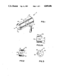
- FIG. 1 is a perspective view of the assembled connector in accordance with the subject invention.
- FIG. 2 is a bottom plan view of the second shell of the connector.
- FIG. 2A is a bottom plan view of an alternate embodiment of the second shell shown in FIG. 2.
- FIG. 3 is a side elevational view of the second shell shown in FIG. 2.
- FIG. 4 is a bottom plan view of the first shell of the subject connector.
- FIG. 5 is a side elevational view of the first shell as viewed from the left side of FIG. 4.
- FIG. 6 is a front elevational view of the eyelet of the subject connector.
- FIG. 7 is an exploded cross-sectional view of the connector at a stage during its assembly.
- FIG. 8 is a cross-sectional view of the assembled connector.
- FIG. 9 is a side elevational view of the connector as viewed from the right side shown in FIG. 8.
- the connector of the subject invention is illustrated in FIG. 1, and is identified generally by the numeral 10.
- the connector 10 includes a dielectric insert 12 at its mating end to enable the connector 10 to be matably joined with a corresponding connector.
- the dielectric insert 12 includes a plurality of apertures 14 in which terminals (not shown) are securely mounted.
- the connector 10 is depicted as being the female half of a connector assembly, it is to be understood that the structure disclosed herein can be incorporated into a connector having male terminals.
- the connector 10 is engageable with a cable 16 having a plurality of conductors (not shown) therein.
- the connector 10 is constructed, as explained in detail below, to enable the axis of the cable 16 extending from the connector 10 to be aligned substantially at a right angle to the longitudinal or mating axis defined by the insert 12 and the terminals mounted therein.
- the connector 10 as shown generally in FIG. 1, comprises an eyelet 18, a first shell 20 and a second shell 22.
- the eyelet 18 securely surrounds and engages the cable 16, and extends into and securely engages the second shell 22 of the connector 10.
- the specific construction which enables the eyelet 18 to securely engage both the cable 16 and the second shell 22 is described in greater detail below.
- the connector 10 further comprises a first shell 20 which is of generally tubular construction and is securely telescopingly engaged in the second shell 22.
- the first shell 20 is generally tubular, and includes a central opening into which the dielectric insert 12 is inserted and retained.
- a coupling nut 24 is mounted to the forward end of the first shell 20 to permit relative rotation therebetween.
- the inner surface of the coupling nut 24 is characterized by an array of internal threads which enable the connector 10 to be securely mechanically joined to another component (not shown).
- the second shell 22 of the connector 10 is shown in greater detail in FIGS. 2 and 3.
- the second shell 22 is of generally cylindrical construction with a closed rear end 26 and an open forward end 28 such that a generally cylindrical cavity having an internal diameter "a" extends into the forward end 28.
- a generally cylindrical peripheral side wall 30 extends between the opposed rear and forward ends 26 and 28, and is characterized by a generally cylindrical peripheral aperture 32 extending entirely therethrough intermediate the opposed ends 26 and 28.
- the aperture 32 has a diameter indicated by dimension "b" in FIG. 2.
- FIG. 2A shows an alternate second shell 22a which has a closed rear end 26a, an open forward end 28a and a cylindrical side wall 30a, all of which are dimensionally identical to corresponding parts of the second shell 22 shown in FIGS. 2 and 3.
- the second shell 22a includes a flared-entry arcuate cutout 32a extending through the peripheral side wall 30a from the forward end 28a to a location intermediate the opposed ends 26a and 28a.
- the first shell 20 is illustrated in FIGS. 4 and 5 and is of generally tubular construction with opposed forward and rear opened ends 34 and 36 respectively.
- a cylindrical peripheral side wall 38 extends between the opposed forward and rear ends 34 and 36.
- a generally annular groove 40 extends into the exterior surface of the first shell 20 in proximity to the forward end 34.
- the inwardly extending annular groove 40 enables the forward end 34 to be readily and precisely flared outwardly, thereby enabling the coupling nut 24 to be rotatably mounted thereon.
- the forward end 34 of the first shell 20 defines an internal diameter "c" as shown in FIG. 4 which enables the dielectric insert 12 to be slidably inserted therein and frictionally retained in position.
- the dielectric insert 12 to be employed with the subject connector 10 preferably is formed from a polyester elastomer having a high coefficient of friction to enable a secure and environmentally sealed engagement between the first shell 20 and the insert 12.
- the insert 12 may be molded from a HYTREL polyester elastomer having a SHORE A Durometer hardness of 90 coupled with the high coefficient of friction.
- the first shell 20 and the insert 12 may comprise compatible arrays of keys and keyways to achieve a selected angular orientation of the terminals therein.
- the first shell 20 defines a major external diameter "d" which is slightly greater than the internal diameter "a" of the second shell 22.
- the internal diameter "a" of the second shell 22 may be in the range 0.4885-0.4900 inch, while the major external diameter "d” of the first shell 20 may be in the range of 0.4910-0.4925 inch.
- the first shell 20 is provided with a reduced diameter portion adjacent the extreme rear end 36 to facilitate the initial insertion of the first shell 20 into the slightly smaller second shell 22.
- a minor external diameter portion 42 is defined immediately adjacent the rear end 36 with a diameter "e" which is less than the internal diameter "a" of the second shell 22.
- a generally conical tapered portion 44 extends between the portions of the first shell 20 defining the minor and major diameter portions thereof.
- the first shell 20 further comprises a generally arcuate cutout 46 extending through the cylindrical side wall 38 from the rear end 36 thereof.
- the cutout portion 46 preferably defines a radius "f" which may be 0.105 inch, but which preferably converges into a wider opening as indicated by dimension "g" at the extreme rear end 36.
- dimension "g” may be approximately 0.270 inch.
- the overall depth of the cutout 46, as measured from the rear end 36 and as indicated by dimension "h” in FIG. 4 is less than or equal to the distance "i" between the rear wall 26 and the front of aperture 32 of the second shell 22 as shown in FIG. 2.
- the crimpable eyelet 18 is shown in greater detail in FIG. 6.
- the eyelet 18 comprises an enlarged flange 48 adjacent one end and a generally cylindrical portion 50 extending therefrom.
- the eyelet 18 is hollow with an internal diameter permitting the cable 16 to be slid tightly therethrough.
- the generally cylindrical portion 50 of the eyelet 18 has a thin crimpable side wall thickness "j" of approximately 0.011 inch.
- the overall external diameter "k" of the cylindrical portion 50 of eyelet 18 is less than the maximum dimension "g" of the cutout portion 46 on the first shell 20.
- the external diameter "k” of the eyelet 18 preferably is greater than twice the radius "j" defined by the base of the cutout portion 46 on the first shell 20.
- the external diameter "k” of cylindrical portion 50 on the eyelet 18 will equal approximately 0.215 inch.
- the thin walled cylindrical portion 50 of the crimpable eyelet 18 can only be fully seated in the cutout portion 46 of the first shell 20 by deformation of the eyelet 18.
- the relatively small thickness "j" of the cylindrical walls of eyelet 18 facilitates this deformation.
- the connector 10 of the subject invention is assembled as shown in FIGS. 7-9.
- the assembly steps described herein may be varied from one application to the next, as will be appreciated by the person skilled in this art.
- the first step in the assembly process is to slide the coupling nut 24 over the forward end 34 of the first shell 20.
- the extreme front end 34 will then be flared outwardly to retain the coupling nut 24 on the first shell 20, but to permit relative rotation and controlled axial movement therebetween.
- the cable 16 is then directed through the end of the eyelet 18 having the flange 48 thereon, and is further directed through the aperture 32 in the second shell 22 such that the cable may continue out the opened forward end 28 of the second shell 22.
- the insert 12 with the conductors 54 and the terminals 56 therein is urged into frictional engagement within the first shell 20 to define a subassembly.
- the first shell 20 is then urged toward the second shell 22, while the cable 16 is continually urged through the eyelet 18 and the aperture 32 in the second shell 22.
- the cable is merely moved longitudinally relative to the cutout 32a. Continued movement of these components toward one another will cause the first shell 20 to be force fit into the second shell 22 or 22a, and will further urge the eyelet 18 into the aperture 32 of the second shell 22 or the cutout 32a of the alternate second shell 22a.
- the first shell 20 is rotationally aligned about its axis and relative to the second shell 22 or 22a such that the cutout 46 of the first shell 20 is aligned with the aperture 32 in the second shell 22 or the cutout 32a in the alternate second shell 22a.
- the cutout portion 46 of the first shell 20 will engage the portion of the eyelet 18 extending through the aperture 32, as shown most clearly in FIG. 8.
- the eyelet 18 has a relatively thin side wall of dimension "j".
- the external diameter "k" of the eyelet 18 is greater than the diameter "2f" of the cutout 46.
- the changes in selected dimensions of the eyelet 18 resulting from the crimping will securely engage the eyelet with the aperture 32 in the second shell 22 or the cutout 32a in the alternate second shell 22a.
- the eyelet 18 will be deformed or crimped to securely and sealingly engage the cable 16, and to simultaneously securely engage the shells 20 and 22 or 20 and 22a.
- movement of the cable 16 or the conductors 54 therein relative to the connector 10 is prevented. Consequently, the connector 10 achieves a right angle exit of the conductor 16 therefrom, while positively assuring the absence of strain on the conductors 54. Additionally, this right angle strain relief connection is achieved from easily machined and relatively inexpensive components which enable a low profile to be achieved.
- a connector for electrical and mechanical connection to a cable.
- the connector enables the cable to exit at 90° to the mating axis of the connector, and achieves a well sealed strain relief connection between the cable and the connector.
- the connector comprises telescopingly engageable shells, one of which is provided with an aperture or cutout extending through a side wall portion thereof, while the other is provided with a longitudinally extending cutout portion at one end.
- a relatively thin walled eyelet is tightly slid over the cable and is urged into the aperture of the shell.
- the shells are then slid into telescoped relationship such that the cutout portion in one shell deforms the eyelet in proximity to the aperture or cutout in the other shell. This controlled deformation of the eyelet causes the eyelet to securely engage the cable extending therethrough and to engage the aperture of the shell through which the eyelet is directed.
- the aperture and the cutout must be disposed on separate components of the shell, but the particular orientation is not material.
- the aperture could be disposed on the front shell, while the cutout could be disposed on the rear shell.
- the rear shell may telescopingly engage over or into the front shell, and may be retained in its engaged position with the front shell by either the force fit described above or other appropriate connection means.
- it may be possible to eliminate the eyelet such that the interengagement of the front and rear shells will safely but securely retain the cable to achieve the desired strain relief 90° alignment thereof.
Abstract
Description
Claims (20)
Priority Applications (1)
| Application Number | Priority Date | Filing Date | Title |
|---|---|---|---|
| US07/175,015 US4869686A (en) | 1988-03-30 | 1988-03-30 | Right angle electrical connector |
Applications Claiming Priority (1)
| Application Number | Priority Date | Filing Date | Title |
|---|---|---|---|
| US07/175,015 US4869686A (en) | 1988-03-30 | 1988-03-30 | Right angle electrical connector |
Publications (1)
| Publication Number | Publication Date |
|---|---|
| US4869686A true US4869686A (en) | 1989-09-26 |
Family
ID=22638484
Family Applications (1)
| Application Number | Title | Priority Date | Filing Date |
|---|---|---|---|
| US07/175,015 Expired - Lifetime US4869686A (en) | 1988-03-30 | 1988-03-30 | Right angle electrical connector |
Country Status (1)
| Country | Link |
|---|---|
| US (1) | US4869686A (en) |
Cited By (21)
| Publication number | Priority date | Publication date | Assignee | Title |
|---|---|---|---|---|
| US5570443A (en) * | 1994-04-13 | 1996-10-29 | Framatome Connectors International | Combined beam waveguide and metal cable plug connector |
| US5929386A (en) * | 1997-09-11 | 1999-07-27 | Ryobi North America, Inc. | Power cord set for an electric tool |
| US6083038A (en) * | 1998-08-05 | 2000-07-04 | Osram Sylvania Inc. | Bracket assembly |
| US6123568A (en) * | 1998-09-18 | 2000-09-26 | Curtis Computer Products, Inc. | Cable-orienting and space saving cable connector assembly |
| US6231375B1 (en) * | 1998-01-30 | 2001-05-15 | Yazaki Corporation | Wire holding structure for connector housing |
| AT407927B (en) * | 1994-12-05 | 2001-07-25 | Framatome Connectors Int | COMBINED FOCUS / METAL CABLE CONNECTOR |
| US6325661B1 (en) * | 1999-03-18 | 2001-12-04 | Sumitomo Wiring Systems, Ltd. | Waterproof connector |
| US20030194902A1 (en) * | 2002-04-16 | 2003-10-16 | Huang George Ying-Liang | Electrical connector assembly with a cable guiding member |
| US6644863B1 (en) * | 1999-03-09 | 2003-11-11 | Sony Corporation | Angled optical fiber connector |
| US6648674B1 (en) * | 2001-09-20 | 2003-11-18 | Neutrik Aktiengesellschaft | Electrical connector |
| US20050164543A1 (en) * | 2004-01-23 | 2005-07-28 | Carlyle, Inc. | Electrical connector assembly with reconfigurable strain relief |
| US20060057885A1 (en) * | 2002-12-09 | 2006-03-16 | Atlas Copco Tools Ab | Multi-conductor connector plug |
| US20060060374A1 (en) * | 2004-09-17 | 2006-03-23 | Karl-Heinz Trieb | Swivel connector, cable, and assembly |
| WO2006076985A1 (en) * | 2004-12-06 | 2006-07-27 | Itt Manufacturing Enterprises Inc. | Device for a machine |
| EP1691453A1 (en) * | 2005-02-09 | 2006-08-16 | Times Microwave Systems, Inc. | Handgrip device for coaxial cable, and coaxial cable assembly including handgrip device |
| US20080264668A1 (en) * | 2007-04-30 | 2008-10-30 | Trentent Tye | Angled conductor extender |
| US9142902B2 (en) | 2013-08-01 | 2015-09-22 | Lear Corporation | Electrical terminal assembly |
| US9190756B2 (en) | 2013-08-01 | 2015-11-17 | Lear Corporation | Electrical terminal assembly |
| US9257772B2 (en) | 2013-02-08 | 2016-02-09 | Lear Corporation | Electric connector with a lock to retain a terminal within a housing |
| US20170005429A1 (en) * | 2013-12-18 | 2017-01-05 | Amphenol Fci Asia Pte Ltd | Electrical cable connector and connector assembly thereof |
| US9711926B2 (en) | 2013-11-19 | 2017-07-18 | Lear Corporation | Method of forming an interface for an electrical terminal |
Citations (5)
| Publication number | Priority date | Publication date | Assignee | Title |
|---|---|---|---|---|
| US1752585A (en) * | 1926-03-31 | 1930-04-01 | Western Electric Co | Cord fastener |
| US2171331A (en) * | 1937-07-01 | 1939-08-29 | Gen Electric | Electric cord assembly for vacuum cleaners or the like |
| US2216157A (en) * | 1938-02-10 | 1940-10-01 | Hatfield Wire & Cable Co | Electrical plug connector |
| US2236764A (en) * | 1939-02-08 | 1941-04-01 | Johann G Peterson | Cord grip clip |
| US4758174A (en) * | 1987-01-20 | 1988-07-19 | Molex Incorporated | Environmentally sealed electrical connector |
-
1988
- 1988-03-30 US US07/175,015 patent/US4869686A/en not_active Expired - Lifetime
Patent Citations (5)
| Publication number | Priority date | Publication date | Assignee | Title |
|---|---|---|---|---|
| US1752585A (en) * | 1926-03-31 | 1930-04-01 | Western Electric Co | Cord fastener |
| US2171331A (en) * | 1937-07-01 | 1939-08-29 | Gen Electric | Electric cord assembly for vacuum cleaners or the like |
| US2216157A (en) * | 1938-02-10 | 1940-10-01 | Hatfield Wire & Cable Co | Electrical plug connector |
| US2236764A (en) * | 1939-02-08 | 1941-04-01 | Johann G Peterson | Cord grip clip |
| US4758174A (en) * | 1987-01-20 | 1988-07-19 | Molex Incorporated | Environmentally sealed electrical connector |
Cited By (26)
| Publication number | Priority date | Publication date | Assignee | Title |
|---|---|---|---|---|
| US5570443A (en) * | 1994-04-13 | 1996-10-29 | Framatome Connectors International | Combined beam waveguide and metal cable plug connector |
| AT407927B (en) * | 1994-12-05 | 2001-07-25 | Framatome Connectors Int | COMBINED FOCUS / METAL CABLE CONNECTOR |
| US5929386A (en) * | 1997-09-11 | 1999-07-27 | Ryobi North America, Inc. | Power cord set for an electric tool |
| US6231375B1 (en) * | 1998-01-30 | 2001-05-15 | Yazaki Corporation | Wire holding structure for connector housing |
| US6083038A (en) * | 1998-08-05 | 2000-07-04 | Osram Sylvania Inc. | Bracket assembly |
| US6123568A (en) * | 1998-09-18 | 2000-09-26 | Curtis Computer Products, Inc. | Cable-orienting and space saving cable connector assembly |
| US6644863B1 (en) * | 1999-03-09 | 2003-11-11 | Sony Corporation | Angled optical fiber connector |
| US6325661B1 (en) * | 1999-03-18 | 2001-12-04 | Sumitomo Wiring Systems, Ltd. | Waterproof connector |
| US6648674B1 (en) * | 2001-09-20 | 2003-11-18 | Neutrik Aktiengesellschaft | Electrical connector |
| US6948969B2 (en) * | 2002-04-16 | 2005-09-27 | George Ying-Liang Huang | Electrical connector assembly with a cable guiding member |
| US20030194902A1 (en) * | 2002-04-16 | 2003-10-16 | Huang George Ying-Liang | Electrical connector assembly with a cable guiding member |
| US20060057885A1 (en) * | 2002-12-09 | 2006-03-16 | Atlas Copco Tools Ab | Multi-conductor connector plug |
| US7163417B2 (en) * | 2002-12-09 | 2007-01-16 | Atlas Copco Tools Ab | Multi-conductor connector plug |
| US7029315B2 (en) | 2004-01-23 | 2006-04-18 | Carlyle, Inc. | Electrical connector assembly with reconfigurable strain relief |
| US20050164543A1 (en) * | 2004-01-23 | 2005-07-28 | Carlyle, Inc. | Electrical connector assembly with reconfigurable strain relief |
| US20060060374A1 (en) * | 2004-09-17 | 2006-03-23 | Karl-Heinz Trieb | Swivel connector, cable, and assembly |
| US7304241B2 (en) * | 2004-09-17 | 2007-12-04 | Karl-Heinz Trieb | Swivel connector, cable, and assembly |
| WO2006076985A1 (en) * | 2004-12-06 | 2006-07-27 | Itt Manufacturing Enterprises Inc. | Device for a machine |
| EP1691453A1 (en) * | 2005-02-09 | 2006-08-16 | Times Microwave Systems, Inc. | Handgrip device for coaxial cable, and coaxial cable assembly including handgrip device |
| US20080264668A1 (en) * | 2007-04-30 | 2008-10-30 | Trentent Tye | Angled conductor extender |
| US9257772B2 (en) | 2013-02-08 | 2016-02-09 | Lear Corporation | Electric connector with a lock to retain a terminal within a housing |
| US9142902B2 (en) | 2013-08-01 | 2015-09-22 | Lear Corporation | Electrical terminal assembly |
| US9190756B2 (en) | 2013-08-01 | 2015-11-17 | Lear Corporation | Electrical terminal assembly |
| US9711926B2 (en) | 2013-11-19 | 2017-07-18 | Lear Corporation | Method of forming an interface for an electrical terminal |
| US20170005429A1 (en) * | 2013-12-18 | 2017-01-05 | Amphenol Fci Asia Pte Ltd | Electrical cable connector and connector assembly thereof |
| US9960518B2 (en) * | 2013-12-18 | 2018-05-01 | Amphenol Fci Asia Pte. Ltd. | Electrical cable connector and connector assembly thereof |
Similar Documents
| Publication | Publication Date | Title |
|---|---|---|
| US4869686A (en) | Right angle electrical connector | |
| US7131868B2 (en) | Compression connector for coaxial cable | |
| EP1779470B1 (en) | Compression connector for coaxial cable | |
| EP0624933B1 (en) | Coaxial connector for coaxial cable having a corrugated outer conductor | |
| US7048579B2 (en) | Compression connector for coaxial cable | |
| US4655534A (en) | Right angle coaxial connector | |
| US7753725B2 (en) | Coaxial angle connector | |
| US4593964A (en) | Coaxial electrical connector for multiple outer conductor coaxial cable | |
| US7160149B1 (en) | Coaxial connector and method of connecting a two-wire cable to a coaxial connector | |
| JP3356301B2 (en) | Coaxial contact and method of connecting it to coaxial cable | |
| US4619496A (en) | Coaxial plug and jack connectors | |
| JP3217785B2 (en) | Electrical connector | |
| US7371113B2 (en) | Coaxial cable connector with clamping insert | |
| JP3012116B2 (en) | Coaxial connector assembly | |
| US5037328A (en) | Foldable dielectric insert for a coaxial contact | |
| US4690481A (en) | Coaxial coupling | |
| US5167520A (en) | Cup fit plug connector | |
| JPH0773937A (en) | Connector for co-axial cable | |
| US3297979A (en) | Crimpable coaxial connector | |
| US5860833A (en) | Electrical connector having a probe positionable between a pair of spaced positions | |
| EP3440742B1 (en) | Angled coaxial connectors for receiving electrical conductor pins having different sizes | |
| US5364285A (en) | Waterproof connector | |
| US4678261A (en) | L-type coaxial plug connector | |
| JPH0711778U (en) | Waterproof plug and wire terminal with waterproof plug | |
| US5975948A (en) | Coaxial cable connector |
Legal Events
| Date | Code | Title | Description |
|---|---|---|---|
| AS | Assignment |
Owner name: MOLEX INCORPORATED, 2222 WELLINGTON COURT, LISLE, Free format text: ASSIGNMENT OF ASSIGNORS INTEREST.;ASSIGNORS:MICHAELS, LEONARD H.;MILLER, ROBERT A.;REEL/FRAME:004958/0622 Effective date: 19881004 Owner name: MOLEX INCORPORATED, A CORP. OF DE,ILLINOIS Free format text: ASSIGNMENT OF ASSIGNORS INTEREST;ASSIGNORS:MICHAELS, LEONARD H.;MILLER, ROBERT A.;REEL/FRAME:004958/0622 Effective date: 19881004 |
|
| STCF | Information on status: patent grant |
Free format text: PATENTED CASE |
|
| FEPP | Fee payment procedure |
Free format text: PAYOR NUMBER ASSIGNED (ORIGINAL EVENT CODE: ASPN); ENTITY STATUS OF PATENT OWNER: LARGE ENTITY |
|
| FPAY | Fee payment |
Year of fee payment: 4 |
|
| FPAY | Fee payment |
Year of fee payment: 8 |
|
| FPAY | Fee payment |
Year of fee payment: 12 |