US4868123A - Apparatus for the intensive, controlled production of microorganisms by photosynthesis - Google Patents
Apparatus for the intensive, controlled production of microorganisms by photosynthesis Download PDFInfo
- Publication number
- US4868123A US4868123A US07/252,186 US25218688A US4868123A US 4868123 A US4868123 A US 4868123A US 25218688 A US25218688 A US 25218688A US 4868123 A US4868123 A US 4868123A
- Authority
- US
- United States
- Prior art keywords
- photobioreactor
- tubes
- group
- liquid medium
- microorganisms
- Prior art date
- Legal status (The legal status is an assumption and is not a legal conclusion. Google has not performed a legal analysis and makes no representation as to the accuracy of the status listed.)
- Expired - Fee Related
Links
Images


Classifications
-
- C—CHEMISTRY; METALLURGY
- C12—BIOCHEMISTRY; BEER; SPIRITS; WINE; VINEGAR; MICROBIOLOGY; ENZYMOLOGY; MUTATION OR GENETIC ENGINEERING
- C12M—APPARATUS FOR ENZYMOLOGY OR MICROBIOLOGY; APPARATUS FOR CULTURING MICROORGANISMS FOR PRODUCING BIOMASS, FOR GROWING CELLS OR FOR OBTAINING FERMENTATION OR METABOLIC PRODUCTS, i.e. BIOREACTORS OR FERMENTERS
- C12M21/00—Bioreactors or fermenters specially adapted for specific uses
- C12M21/02—Photobioreactors
-
- C—CHEMISTRY; METALLURGY
- C12—BIOCHEMISTRY; BEER; SPIRITS; WINE; VINEGAR; MICROBIOLOGY; ENZYMOLOGY; MUTATION OR GENETIC ENGINEERING
- C12M—APPARATUS FOR ENZYMOLOGY OR MICROBIOLOGY; APPARATUS FOR CULTURING MICROORGANISMS FOR PRODUCING BIOMASS, FOR GROWING CELLS OR FOR OBTAINING FERMENTATION OR METABOLIC PRODUCTS, i.e. BIOREACTORS OR FERMENTERS
- C12M23/00—Constructional details, e.g. recesses, hinges
- C12M23/02—Form or structure of the vessel
- C12M23/06—Tubular
-
- C—CHEMISTRY; METALLURGY
- C12—BIOCHEMISTRY; BEER; SPIRITS; WINE; VINEGAR; MICROBIOLOGY; ENZYMOLOGY; MUTATION OR GENETIC ENGINEERING
- C12M—APPARATUS FOR ENZYMOLOGY OR MICROBIOLOGY; APPARATUS FOR CULTURING MICROORGANISMS FOR PRODUCING BIOMASS, FOR GROWING CELLS OR FOR OBTAINING FERMENTATION OR METABOLIC PRODUCTS, i.e. BIOREACTORS OR FERMENTERS
- C12M23/00—Constructional details, e.g. recesses, hinges
- C12M23/56—Floating elements
-
- C—CHEMISTRY; METALLURGY
- C12—BIOCHEMISTRY; BEER; SPIRITS; WINE; VINEGAR; MICROBIOLOGY; ENZYMOLOGY; MUTATION OR GENETIC ENGINEERING
- C12M—APPARATUS FOR ENZYMOLOGY OR MICROBIOLOGY; APPARATUS FOR CULTURING MICROORGANISMS FOR PRODUCING BIOMASS, FOR GROWING CELLS OR FOR OBTAINING FERMENTATION OR METABOLIC PRODUCTS, i.e. BIOREACTORS OR FERMENTERS
- C12M29/00—Means for introduction, extraction or recirculation of materials, e.g. pumps
- C12M29/20—Degassing; Venting; Bubble traps
- C12M29/22—Oxygen discharge
Definitions
- the present invention relates to an apparatus for the intensive, controlled production of microorganisms or biomass, by photosynthesis and on an industrial scale, using simple components and which has a simple construction.
- the invention is applicable to the production of any photosynthetic material, i.e. any life form liable to development and photosynthesis in an appropriate nutrient liquid medium in the presence of solar radiation and carbon dioxide, to the production of metabolites and polysaccharides possibly excreted by microorganisms.
- photosynthetic microorganisms are vegetable tissues and monocellular organisms containing chloroplasts, photosynthetic bacteria and microalgae.
- Photosynthesis is the transformation, as a result of solar energy, of carbon dioxide into primary hydrocarbon material, oxygen being the main by-product of said biochemical transformation.
- the latter can be symbolized by the following Myers equation:
- Nitrogen is supplied in the form of nitrate, urea of ammonium salts introduced into the liquid medium containing the microorganisms.
- the culture and development of the microorganisms by photosynthesis is carried out in a photobioreactor. In order to ensure a good operation of the latter and an optimum development of the microorganisms, it is necessary for a certain number of physical phenomena to be controlled.
- the liquid medium containing the microorganisms must be constantly charged with dissolved CO 2 and nitrogen, the nitrogen and dissolved CO 2 concentration being maintained at an optimum level throughout the culture and the development of the microorganisms.
- the temperature of the liquid medium containing the microorganisms, its salinity, its concentration of photosynthetic cells, as well as its pH must be very carefully regulated.
- the presently known photobioreactors are constituted by an assembly of transparent tubes placed in the form of a raft above a large expanse of water (lagoon, pond, pool, ocean) serving as cooling sources for the microorganism-charged liquid medium circulating in the tubes.
- tubular photobioreactors examples are given in FR-A-2 324 224 and 2 361 060.
- plastic balls are introduced into the tubes containing the culture medium. These balls, which are circulated with the culture medium, ensure an agitation and cleaning of the tubes by friction on the walls of the latter.
- Such a system for the cleaning and degassing of the tubes of a photobioreactor is described in FR-A-2 576 034.
- the invention relates to an apparatus for the production of microorganisms by photosynthesis having one or more tubular photobioreactors to be placed on an expanse of water, preventing any gaseous pockets and in particular oxygen within the said tubes.
- the invention therefore specifically relates to an apparatus for the intensive, control production by photosynthesis of microorganism suspended in a liquid medium:
- At least one photobioreactor to be placed on an expanse of water and having a first group of tubes, which are transparent to light and in which circulates the liquid medium, and a second group of tubes disposed and maintained beneath the first group of tubes by means of regularly spaced, detachable interpolated members, said second group being able to make the photobioreactor submersible or non-submersible,
- At least one carbonator connected to the inlet of the photobioreactor in order to charge the liquid medium with the CO 2 necessary for photosynthesis
- At least one degassing means connected to the photobioreactor for eliminating from the liquid medium the oxygen produced by the microorganisms and possibly the undissolved CO 2 and
- At least one expansion tank connected to the photobioreactor in order to reduce possible variations in the volume within the photobioreactor.
- the tubes of the first group are interconnected so as to form a coil.
- the tubes of the second group are interconnected so as to form another coil.
- the presence of the interpolated member makes it possible to render perfectly integral the two groups of tubes of the photobioreactor and in particular prevent the misalignment of the tubes, thus permitting by a linear entrainment of the liquid medium up to the degassing means, the circulation of gaseous pockets possibly present in the tubes of the first group, such as oxygen resulting from the photosynthesis. If balls are possibly used for cleaning the inner wall of the tubes of the first group, the presence of the interpolated members aids the circulation of these balls.
- the interpolated members can be easily fitted and make it possible to prevent the tubes sticking or welding to one another, which prevents the changing of a single tube in the case of deterioration thereof.
- the photobioreactor when the temperature of the microorganism-charged liquid exceeds an upper reference temperature the photobioreactor is immersed through the deflation of the tubes of the second group, said deflation being ensured with the aid of an automaton. Conversely, when the temperature of the liquid medium is below the minimum reference temperature, the automaton controls the inflation of the tubes of the second group with compressed air.
- the immersion of the photobioreactor can also be ensured by introducing a relatively heavy liquid into the tubes of the second group, whilst floating can be ensured by injecting a light fluid other than air.
- interpolated members according to the present invention also improves the heat regulation of the photobioreactor, particularly when tubes of the second group are intended to be inflated with compressed air, so as to float the photobioreactor, as well as deflated with a view to the total or partial immersion of the photobioreactor.
- the tubes of the first group filled with liquid, heavier than the tubes of the second air-free group might slide between two inflattable tubes and consequently remain constantly and totally immersed.
- a degassing means of a particular design In order to improve the degassing of the photobioreactor and in particular in order to eliminate the oxygen produced, by photosynthesis, by the microorganisms, use is made of a degassing means of a particular design.
- This degassing means can be used with a tubular photobioreactor equipped with interpolated members according to the invention, or with tubular photobioreactors according to the prior art not having interpolated members.
- the invention also relates to an apparatus for the intense, controlled production, by photosynthesis, of microorganisms suspended in a liquid medium comprising:
- At least one photobioreactor to be placed on an expanse of water and having a first group of tubes, which are transparent to light and in which circulates the liquid medium and a second group of tubes, positioned beneath the first group, said second group being able to render the photobioreactor submersible or non-submersible,
- At least one carbonator connected to the inlet of the photobioreactor for charging the liquid medium with the CO 2 necessary for photosynthesis
- degassing means connected to the photobioreactor for eliminating from the liquid medium in particular the oxygen produced by the microorganisms, said degassing means having a sealed external enclosure with a longitudinal axis, a U-shaped duct for collecting oxygen, whereof one of the branches is located in the enclosure parallel to said axis and whose base is located on the side of the base of the enclosure, the end of said duct collecting the oxygen issuing into the upper part of the enclosure, at least one supply pipe and at least one discharge pipe for the liquid medium issuing into the lower part of the enclosure and
- At least one expansion tank connected to the photobioreactor for reducing possible variations in the volume in said photobioreactor.
- a degassing means prevents the internal dirtying of the tubes of the photobioreactor (by the deposition of microorganisms), thus making it unnecessary to use the self-cleaning balls according to FR-A-2 576 034.
- any static, constant presence of a gas of any type within the tubes of the first group is prejudicial to the use of the photobioreactor. This not only applies to the oxygen produced by the microorganisms, but also to the carbon dioxide introduced into the liquid medium and which is necessary for development of the microorganisms and for the air possibly used as a support gas for the carbon dioxide gas.
- the carbonator according to the invention can be used with a tubular photobioreactor either equipped or not equipped with interpolated members, associated with a degassing means according to the prior art or according to the invention.
- the invention also relates to an apparatus for the intense, controlled production, by photosynthesis, of microorganisms suspended in a liquid medium comprising:
- At least one photobioreactor placed on an expanse of water and having a first group of light-transparent tubes, in which circulates the liquid medium, as well as a second group of tubes, located beneath the first group, said second group being able to make the photobioreactor submersible or non-submersible,
- At least one carbonator connected to the inlet of the photobioreactor for charging the liquid medium with the CO 2 necessary for photosynthesis, said carbonator being of the type having two columns with an intake column in which the liquid medium is charged with CO 2 and a discharge column, connected to the intake column, in which is introduced the CO 2 -charged liquid medium,
- At least one degassing means connected to the photobioreactor for eliminating from the liquid medium the oxygen produced by the microorganisms and
- At least one expansion tank connected to the photobioreactor for reducing possible variations of the volume in the photobioreactor.
- the function of the first column is to bring about a maximum charging of the culture medium with carbon dioxide, whilst the function of the second column is to prevent the entrainment of carbon dioxide into the photobioreactor which has not dissolved in the liquid medium and possibly the air used as a support gas for CO 2 .
- the intake column advantageoulsy has a plunger tube for supplying CO 2 into the liquid medium and whose plunging end is made from variable porosity, fritted stainless steel or glass.
- the first column can have an internal lining.
- the expansion tank or tanks must, according to the invention, be shaped such that there is no accummulation of organic matter and in particular microorganisms, all the microorganisms generally being recycled. In addition, these tanks must be transparent to light.
- the expansion tank or tanks are transparent and formed by an enclosure with rounded edges, whose upper end is sealed by a diamond point cover and whose lower end is funnel-shaped.
- the shape of the tanks may make it possible to carry out a clarification of the culture during certain contaminations, i.e. filling of the tank with the culture, stopping circulation and sedimentation.
- the supernatent part containing the contaminants such as 5 to 10 u microalgae
- the sedimented parts is recycled.
- FIG. 1 an overall diagram of a microorganism production apparatus according to the invention and operating in a continuous manner.
- FIG. 2 in greater detail certain elements of the apparatus of FIG. 1.
- FIG. 3 diagrammatically and in longitudinal section, the photobioreactor tubes in which circulates the culture medium and which are interconnected, according to the invention.
- FIG. 4 in perspective, the two groups of tubes held together with the aid of interpolated members according to the invention.
- FIG. 5 diagrammatically and in longitudinal section, a degassing means according to the invention.
- FIG. 6 diagrammatically and in longitudinal section, a carbonator according to the invention.
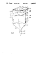
- FIG. 7 diagrammatically and in perspective, an expansion tank according to the invention.
- FIG. 8a is a schematic illustration of the regulation system of the invention.
- FIG. 8b shows graphs of solar energy, CO 2 supply and unconsumel CO 2 variations.
- the apparatus for producing microorganismsby photosynthesis comprises one or more approximately 200 1 expansion tanks 2 for receiving a solution of microalgae 1, injected with the aid of a pump 4 into tubular photobioreactor 6.
- the latter are to be placed on the surface of an expanse of water 8.
- the number of such photobioreactors is a function of the envisaged biomass production.
- Tanks 2 serve to reduce possible variations in the volume within the photobioreactors due to possible gas accumulation.
- the culture from all the photobioreactors passes into the tanks.
- the latter constitute a volume representative of the entire culture medium 1 of the apparatus in production. It is at this level where the supply of microalgae and culture medium takes place, as will be subsequently shown relative to FIG. 7.
- the pipes 10 for the supply of culture medium to the photobioreactors are in each case equipped with twin column carbonators 12 in order to charge the culture medium 1 with the carbon dioxide necessary for photosynthesis.
- the number of carbonators 12 is generally the same as the number of photobioreactors.
- the CO 2 supply takes place mixed with air, with up to 80% by volume ofCO 2 in the mixture.
- a mixerflowmeter 14 mounted on the air supply pipe 16 and on the CO 2 supply pipe 18 is provided at the inlet for the gases into each carbonator 12.
- a system 19 makes it possible to regulate the CO 2 quantity introduced into the photobioreactors as a function of solar energy.
- This production apparatus also comprises a tank 20 used for the preparation, accompanied by stirring, of the nutrient medium necessary forthe growth of he microorganisms.
- This nutrient medium prior to introduction via a supply pipe 22 into the tanks 2 containing the microalgae, is filtered by means of two Philippe-type filters 24,26, respectively ensuring the passage of the mineral and organic elements necessary for the growth of microorganisms, of 40 and 1 ⁇ m.
- the nutrient medium is injected into tanks 2 by a pump 28.
- the microorganisms produced in the photobioreactor 6 are extracted at the outlet of each of these photobioreactors, via discharge pipes 30, with theaid of a volumetric pump 32.
- the feed of culture medium 1 of extraction pump 32 is equal to that of the nutrient medium injection pump 28, so thatthe culture volume in the photobioreactor remains constant.
- the microorganisms produced are recovered in a tank 34, under continuous agitation.
- degassing means 36 are provided on either side of the photobioreactor 6 (i.e. two degassing means per photobioreactor).
- the photobioreactors are constituted by a firstgroup of parallel tubes 38 made from a transparent, flexible plastic material, such as polyethylene. These tubes receive the culture medium 1 charged with nutrient elements and CO 2 necessary for the growth of the microorganisms. They have an approximate length of 15.8 m and an internal diameter of 63 mm. Tubes 38 are interconnected at their two ends,as shown in FIG. 3, with the aid of two collectors, respectively upstream 40 and downstream 42.
- These collectors 40,42 are made from polypropalene and have several compartments or bent connections 44.
- the total number of compartments 44 of the upstream and downstream collectors is equal to the number of tubes 38.
- Each compartment or connection 44 of the upstream collector 40 comprises anintake port 46 for receiving a first tube 38a and a discharge port 48 for receiving a second tube 38b.
- the fixing of tubes 38a and 38b to collector 40 is ensured with the aid of identical stuffing box systems respectively 50a and 50b.
- two internal sleeves 52a, 52b are respectively located intubes 38a and 38b and two external tubes 54a, 54b into which are fitted tubes 38a and 38b respectively are respectively located in the intake port46 and discharge port 48 of compartments 44.
- Each of the external sleeves 54a, 54b is provided with a groove 56a, 56b, in which are placed screws 58a, 58b mounted on connection 44, respectively at the inlet and outlet ofthe latter.
- Elastomer O-rings respectively 59a and 59b located on the outer face of theexternal sleeves 54a, 54b ensure the sealing of the assembly.
- the internal sleeves 52a, 52b and the external sleeves 54a, 54b are made from polypropalene.
- the assembly of the downstream collector 42 and tubes 38 is identical to that of the upstream collector 40 and tubes 38.
- Each photobioreactor 6 has a single culture medium supply pipe 10, mounted at the inlet 43 of the upstream collector 40 and a single discharge pipe 30 for said medium, fitted to the outlet 45 of collector 40, the intake pipe 10 being fitted on the first photobioreactor tube 38 and the discharge pipe 30 on the final photobioreactor tube 38.
- each connection 44 of the upstream and down stream collectors 40,42 respectively is provided with an orifice 60 for the connection of degassing means 36. This connection is ensured with the aid of flexible pipes for the supply 61 and the discharge 63 of the culture medium (FIGS. 2 and 5).
- each photobioreactor 6 is provided with a second group of tubes 62 placed beneath tubes 38.
- These tubes 62 which are made from a flexible plastics material, e.g. polyethylene, are interconnected in the same way as tubes 38 with the aid of an upstream collector 64 and a downstream collector 65, having bent compartments, so as to form a coil (FIG. 2).
- These tubes 62 which are 16.4 m long and havean internal diameter of 63 mm are to be inflated with compressed air with the aid of an electrovalve 66, thus forming a pneumatic support floating on the surface of the expanse of water 8.
- Electrovalve 66 is controlled by an electronic control circuit 68 connectedto temperature measurement probes or sensors 68 located within tubes 38.
- the temperature probes When the temperature of the culture medium 1 contained in tubes 38 and measured by probes 67 is above a maximum reference temperature (e.g. 29° C.), the temperature probes emit a first signal detected by theelectronic circuit 68, which then controls the deflation of the tubes 62 via electrovalves 71. The deflation of tubes 62 then leads to the total orpartial immersion as a function of the deflation level, of the photobioreactor 6 in the expanse of water 8. As the water is colder than the ambient atmosphere and the culture medium present in the photobioreactor, the culture medium cools.
- a maximum reference temperature e.g. 29° C.
- the probes 67 When the immersed culture medium reaches a temperature, measured by probes 67 which is below a minimum reference temperature (e.g. 17° C.), the probes 67 emit a second signal detected by the electronic circuit 68 controlling electrovalve 66, so as to ensure the inflation with compressedair of tubes 62. The inflation of tubes 62 then leads to the floating of photobioreactor 6. The culture medium then reheats in the open air.
- a minimum reference temperature e.g. 17° C.
- All the supply and discharge pipes for the culture medium, compressed air, etc. and all the electrical connections (probes 67), connected between thephotobioreactors and the other components of the production apparatus, suchas degassing means, carbonators, compressors, etc. are necessarily flexiblein order to be compatible with the immersion or non-immersion of the photobioreactors.
- the components, other than the photobioreactors, are mounted on a hard pontoon 69, as shown in FIG. 2, floating on the water surface 8.
- interpolated members 70 maintain tubes 38 and 62 in place.
- These interpolated members 70 are detachable and regularly spaced roughly every 60 cm (FIG. 2).
- These interpolated members 70 are made from polypropylene and are shaped like a Y, whose tails are supported by support rods 72, made more particularly from polypropylene.
- supports 72 are equipped with orifices 74in which are located the tails of the Y 70.
- the Y's located on either side of the rods 72 and respectively serving to maintain in place tubes 38 and 62, are fixed head to tail.
- the Y's 70 are interconnected with the aid of flexible rubber connections mounted on the branches of the Y's. Tubes 38 and 62 are placed between twoconsecutive Y's 70, their maintaining in place being ensured by elastic connections 76 and support 72.
- Each degassing means 38 has a cylindrical external enclosure 78 with a longitudinal axis 79, provided with a base 80 and closed by a cover 81, aswell as a U-shaped duct 82 for collecting oxygen and the other gases present in the culture medium 1.
- This U-shaped duct 82 has a branch 84 located along the longitudinal axis 79 of enclosure 78.
- the end 85 of branch 84 collects oxygen coming from the culture medium and issues into the upper part of enclosure 78 in the vicinity of cover 81.
- the base 86 ofthe U-shaped duct is parallel to the base 80 of enclosure 78.
- the oxygen flow direction in degassing means 36 is indicated by arrows F2.
- the flexible supply pipes 61 for the oxygen-charged culture medium (generally 60% by volume of oxygen) and the flexible discharge pipes 63 for the deoxygenated culture medium and which are generally degassed issueat the base of the degassing means and are fixed to the base 80 of enclosure 78.
- the degassing means 36 are supported by feet 87, whose height H is regulated in such a way that the enclosure 78 of the degassing means is never filled with culture medium, no matter whether thephotobioreactor are immersed or float.
- the culture height in the tubes 63 is determined by the internal pressure in tubes 38.
- the microorganisms of culture medium 1 have a permanent need for CO 2 , hence the need to constantly charge the culture medium with dissolved CO 2 .
- a carbonator 12 connected to the intake of each photobioreactor, as shown in FIG. 6.
- This carbonator has a cylindrical inlet column 88, which is sealed at its two ends and which optionally contains a lining 90 such as Raschig rings or Bert supports.
- a lining 90 such as Raschig rings or Bert supports.
- the culture medium arriving at the base of column 88 is charged with CO 2 introduced with the aid of a plunger tube 92, whose plunging end 94 is made from variable porousity fritted glass, in order to improve the CO 2 dissolving in liquid medium 1.
- This inlet column 88 is connected to the upper part of an outlet column 96 into which is introduced the CO 2 -charged liquid medium.
- Column 96 prevents the entrainment of C 2 and possibly support gas not dissolvedin the culture medium to the associated photobioreactor.
- a pipe 98 for the discharge of undissolved CO 2 is provided at the top of the outlet column 96.
- F3 indicated the flow direction of the liquid medium 1 in the carbonator.
- the expansion tanks 2 like the other parts of the production apparatus, also help to prevent the deposition of microorganisms in the photobioreactor tubes 38 and consequently improve the efficiency of the said photobioreactors. To this end, use is advantageously made of tanks ofthe type shown in FIG. 7.
- the shown tank has a parallelipipedic enclosure, whereof the lower end 102 is shaped like a funnel.
- This funnel or siloshaped tank has a widened bottom and permits the sedimentation and total recycling of the suspended organic matter (microorganisms plus products excreted by the microorganisms).
- the tank has no sharp edge and the angles are rounded in order to prevent excessive fixing of the microorganisms and in order to facilitate the cleaning. It also has a diamond tip cover 104 in order to prevent the accumulation of condensation, the tip of the cover being directed towards the top of the tank. Cover 104 is fixed to enclosure 100 by metal clips 106 or butterfly screws. An O-ring 108 ensures the necessary sealing between the enclosure and the cover.
- the enclosure 100 of the tank and its cover 104 are transparent to permit observation, but also to combat the contaminations of certain light-sensitive microorganisms. It is made from Plexiglass or PVC (polyvinylchloride).
- a culture (microorganism) intake 110 permits a central filling of the hopper with microorganisms.
- supply pipes 112,22,114, and 116 are provided for the respective introduction into the tank 2 of the culture medium during the filling of the apparatus, the culture medium during continuous operation, the pH regulator (acid or basic) and the antifoaming agent.
- a high level probe 118 and a low level probe 120 respectively make it possible to prevent an overflow or complete emptying of the tank 2 during continuous operation of the production apparatus.
- a first planar metal grid 122 and a second metal grid 124 are provided in the upper part of the tank.
- the first grid with a 1 cm mesh makes it possible, any use of self-cleaning polyurethane balls to recover the latter.
- the second grid of 1 mm mesh and in diamond point makes it possible to recover large cellular aggregates resulting from the selfcleaning by the balls.
- the tip of the grid is directed towards the bottom of the tank.
- Culture medium is discharged to the photobioreactors by pipe 126, a stop valve 128 being fitted thereto at the lower end 102 ofthe tank.
- a regulation 19 of the CO 2 supply of the culture medium as a function of the solar radiation is provided.
- This regulation system 19 is shown in FIG. 8a. It comprises a pyranometer 130 supplying a voltage of 0 to 10 mV representing the light energy variations. This electric signal is amplified with the aid of a variable gain amplifier 132 between 0 and 5 V. The maximum amplification representsthe flow rate of valve 134 when completely opened and which is mounted on pipe 18 (FIG. 1). A RC circuit 136 makes it possible to reduce the response of valve 134 to very short duration light variations.
- variable gain amplifier 132 makes it possible to modify the sensitivity of system 19, i.e. the choice of the light intensity level determining the complete opening of valve 134.
- a regulation of the zero threshold S makes it possible to choose the solar energy threshold triggering the opening of valve 134.
- This adaptation makes it possible to take account of the compensation point of the photosynthesis microorganisms.
- the amplified signal leaving circuit 136 is supplied to an electronic valvecontrol circuit 138, valve 134 being an electronic valve of type 5850TR.
- the valve can be manually controlled by an external supply 140 (0-5 V) or automatically by means of a compute 142.
- a matching circuit 144 is locatedbetween the computer and the RC circuit.
- this regulating system 19 makes it possible to supply the culture medium with CO 2 as a function of the variations of the light energy E during the time t expressed in minutes.
- Curve I represents the solar energy variations
- curve II the variations in the CO 2 supply of the culture medium
- curve III the unconsumed CO 2 variations.
- the photosynthesis activity (fixing of the CO 2 by the microorganisms) is proportional to the light intensity.
- the intensity of the solar flux is variable during the day, being at a minimum morning and evening and at a maximum when the sun is at the zenith.
- a constant CO 2 supply leads to significant CO 2 losses morning and evening (low photosynthesis activity) and sometimes to a limitation of the photosynthesis by lack of CO 2 when the light intensity is at a maximum.
- the CO 2 regulation makes it possible to economize on CO 2 , because its supply is proportional to the biological demand.
- the production apparatus according to the invention can be used for the development and culture of plant cells or unicellular algae, such as thosedescribed in the publication by G. Gudin and C. Thepenier "Bioconversion ofsolar energy into organic chemicals by microalgae” published in Advances inBiotechnological Processes 6, pp 73-110, 1986.
- the nutrient media of the latter contain various mineral salts, metallic salts, amino acids, vitamins and growth regulators. Examples of nutrient elements usable in the invention are illustrated by FR-A-2 324 224 and FR-A-2 361 060.
- the production apparatus described hereinbefore permits an industrial production of approximately 60 tonnes per annum of biomass such as porphyridium cruentum, scenedesmus acutus, dunalulla on an industrial scale using tubular photobioreactors distributed over a water surface of 1hectare, operating 300 days per annum and with an illumination period of onaverage 12 hours daily (which corresponds to a solar energy of 950 W/m 2 ), a fixed CO 2 quantity per annum of 56,000 m 3 , i.e. 110 tonnes per annum and a daily nutrient medium quantity of 50 m 3 , which corresponds to approximately 30 kg of urea per day, the oxygen quantity discharged into the atmosphere being 56,000 m 3 per annum, or154 tonnes per annum.
- biomass such as porphyridium cruentum, scenedesmus acutus, dunalulla
- tubular photobioreactors distributed over a water surface of 1hectare, operating 300 days per annum and with an illumination period of onaverage 12 hours daily (which corresponds to a solar energy of
Abstract
Description
6.14 CO.sub.2 +3.65 H.sub.2 O+NH.sub.3 →C.sub.6.14 H.sub.10.3 O.sub.2.24 N+6.85 O.sub.2
Claims (15)
Applications Claiming Priority (2)
| Application Number | Priority Date | Filing Date | Title |
|---|---|---|---|
| FR8713647 | 1987-10-02 | ||
| FR8713647A FR2621323B1 (en) | 1987-10-02 | 1987-10-02 | INTENSIVE AND CONTROLLED PRODUCTION DEVICE FOR MICROORGANISMS BY PHOTOSYNTHESIS |
Publications (1)
| Publication Number | Publication Date |
|---|---|
| US4868123A true US4868123A (en) | 1989-09-19 |
Family
ID=9355465
Family Applications (1)
| Application Number | Title | Priority Date | Filing Date |
|---|---|---|---|
| US07/252,186 Expired - Fee Related US4868123A (en) | 1987-10-02 | 1988-09-30 | Apparatus for the intensive, controlled production of microorganisms by photosynthesis |
Country Status (7)
| Country | Link |
|---|---|
| US (1) | US4868123A (en) |
| EP (1) | EP0310522B1 (en) |
| JP (1) | JPH01108973A (en) |
| AU (1) | AU614241B2 (en) |
| DE (1) | DE3888274T2 (en) |
| FR (1) | FR2621323B1 (en) |
| IL (1) | IL87832A (en) |
Cited By (79)
| Publication number | Priority date | Publication date | Assignee | Title |
|---|---|---|---|---|
| US5100626A (en) * | 1990-05-24 | 1992-03-31 | Levin Andrew E | Binding assay device with removable cassette and manifold |
| EP0494887A1 (en) * | 1989-10-10 | 1992-07-22 | Aquasearch Inc | Process and apparatus for the production of photosynthetic microbes. |
| US5151347A (en) * | 1989-11-27 | 1992-09-29 | Martek Corporation | Closed photobioreactor and method of use |
| US5173562A (en) * | 1990-10-29 | 1992-12-22 | Chisso America Inc. | Liquid crystal polymer composition containing bisphenol A in combination with 4,4'-thiodiphenol |
| US5242827A (en) * | 1991-03-28 | 1993-09-07 | Commissariat A L'energie Atomique | Apparatus for the automatic, continuous cleaning of the pipe of the solar receptor of a photobioreactor |
| US5534417A (en) * | 1992-06-12 | 1996-07-09 | Ben-Gurion University Of The Negev | Microorganism growth apparatus |
| US5536654A (en) * | 1993-06-11 | 1996-07-16 | Heliosynthese S.A. Centre D'affaires Actimark Bureau | Process for the production and extraction of thermostable superoxide-dismutases from a photosynthetic microorganism culture |
| US5541056A (en) * | 1989-10-10 | 1996-07-30 | Aquasearch, Inc. | Method of control of microorganism growth process |
| US5659977A (en) * | 1996-04-29 | 1997-08-26 | Cyanotech Corporation | Integrated microalgae production and electricity cogeneration |
| US5714058A (en) * | 1994-09-16 | 1998-02-03 | Agency Of Industrial Science And Technology | Apparatus for accelerating revival of environment |
| US5741702A (en) * | 1995-06-21 | 1998-04-21 | Lorenz; Thomas | System for processing gases containing carbon dioxide |
| GB2335199A (en) * | 1998-03-11 | 1999-09-15 | Applied Photosynthetics Limite | Photobioreactor apparatus |
| GB2330589B (en) * | 1997-10-22 | 2002-03-06 | Stephen Skill | Apparatus and method for culture of photosensitive organisms |
| US6416993B1 (en) | 1998-12-11 | 2002-07-09 | Biotechna Environmental International, Ltd. | Method for treating a waste stream using photosynthetic microorganisms |
| US6465240B1 (en) | 1998-12-11 | 2002-10-15 | Biotechna Environmental International, Ltd. | Method for treating a waste stream using photosynthetic microorganisms |
| US6492149B1 (en) * | 1998-10-19 | 2002-12-10 | Institut Francais De Recherche Pour L'exploitation De La Mer | Method for improving the performance of a photobioreactor |
| DE19814253C2 (en) * | 1997-04-10 | 2003-05-22 | Bioprodukte Prof Steinberg Gmb | Process for the production of biomass by photosynthesis |
| WO2004074423A2 (en) * | 2003-02-24 | 2004-09-02 | Universita'degli Studi Di Firenze | Reactor for industrial culture of photosynthetic micro-organisms |
| DE10315750A1 (en) * | 2003-04-04 | 2004-10-21 | Stadtwerke Stollberg | Plant for making micro-algae concentrate, comprises a system for mixing the product intensively with carbon dioxide from e.g. flue gases |
| US20050239182A1 (en) * | 2002-05-13 | 2005-10-27 | Isaac Berzin | Synthetic and biologically-derived products produced using biomass produced by photobioreactors configured for mitigation of pollutants in flue gases |
| US20050260553A1 (en) * | 2002-05-13 | 2005-11-24 | Isaac Berzin | Photobioreactor and process for biomass production and mitigation of pollutants in flue gases |
| US6991919B1 (en) * | 1999-03-17 | 2006-01-31 | Biodiversity Limited | Biochemical synthesis apparatus |
| US7056725B1 (en) * | 2004-12-23 | 2006-06-06 | Chao-Hui Lu | Vegetable alga and microbe photosynthetic reaction system and method for the same |
| GB2425702A (en) * | 2005-05-04 | 2006-11-08 | Questor Ltd C | Photosynthetic apparatus and method using algae |
| US20070094926A1 (en) * | 2003-05-30 | 2007-05-03 | Biolex, Inc. | Bioreactor for growing biological materials supported on a liquid surface |
| US20070104761A1 (en) * | 2005-11-04 | 2007-05-10 | Williams Christopher P | Low radiocarbon nucleotide and amino acid dietary supplements |
| US20070113474A1 (en) * | 2003-05-30 | 2007-05-24 | Biolex, Inc. | Bioreactor for growing biological materials supported on a liquid surface |
| AU2006201799B1 (en) * | 2006-04-28 | 2007-05-31 | Chao-Hui Lu | Alga microbe photosynthetic reaction system and method for the same |
| WO2007143653A2 (en) * | 2006-06-05 | 2007-12-13 | Gs Industrial Design, Inc. | Power or fuel production using photosynthesis |
| ES2288132A1 (en) * | 2006-06-09 | 2007-12-16 | Bernard A.J. Stroiazzo-Mougin | Energy photoconverter for obtaining biofuels |
| US20080009055A1 (en) * | 2006-07-10 | 2008-01-10 | Greenfuel Technologies Corp. | Integrated photobioreactor-based pollution mitigation and oil extraction processes and systems |
| US20080220514A1 (en) * | 2007-03-07 | 2008-09-11 | Chao-Hui Lu | Alga microbe photosynthetic reaction system |
| US20090081743A1 (en) * | 2007-09-24 | 2009-03-26 | Hazelbeck David A | Transportable algae biodiesel system |
| WO2008051865A3 (en) * | 2006-10-20 | 2009-04-09 | Univ Arizona State | System and method for growing photosynthetic cells |
| US20090137025A1 (en) * | 2007-11-24 | 2009-05-28 | Green Vision Energy Corporation | Apparatus for containing, cultivating, and harvesting photosynthetic marine microorganisms within water |
| EP2067850A1 (en) * | 2006-10-02 | 2009-06-10 | Bio Fuel Systems, S.l. | Vertical submersible photobioreactor for obtaining biofuels |
| WO2009090549A3 (en) * | 2008-01-18 | 2009-09-11 | Algae Ltd | Photobioreactor |
| EP2103682A1 (en) * | 2006-12-18 | 2009-09-23 | Bio Fuel Systems, S.l. | Electromagnetic bioaccelerator |
| US20100031561A1 (en) * | 2008-07-25 | 2010-02-11 | Old Dominion University Research Foundation | Raceways for Cultivating Algae |
| US20100105129A1 (en) * | 2008-10-27 | 2010-04-29 | Sanchez-Pina Jose L | Biomass production system |
| US20100105125A1 (en) * | 2008-10-24 | 2010-04-29 | Bioprocessh20 Llc | Systems, apparatuses and methods for cultivating microorganisms and mitigation of gases |
| US20100190236A1 (en) * | 2007-07-03 | 2010-07-29 | Dominique Delobel | System for Producing Microorganisms |
| US20100216203A1 (en) * | 2008-12-05 | 2010-08-26 | Trent Jonathan D | Algae bioreactor using submerged enclosures with semi-permeable membranes |
| US20100236135A1 (en) * | 2007-10-31 | 2010-09-23 | Kleinberger Oren L | System and method for growing algae on human infrastructure |
| US20100248333A1 (en) * | 2009-03-30 | 2010-09-30 | Bartilson Brad W | Photobioreactor System and Method For the Growth of Algae for Biofuels and Related Products |
| DE102009017628A1 (en) | 2009-04-16 | 2010-10-21 | Meiser, Andreas, Dr. | Fumigation device for horizontal photobioreactors |
| US20100279395A1 (en) * | 2008-10-24 | 2010-11-04 | Bioprocessh20 Llc | Systems, apparatuses and methods for cultivating microorganisms and mitigation of gases |
| WO2010141992A1 (en) * | 2009-06-10 | 2010-12-16 | The Crucible Group Pty Ltd | Production of algae |
| US20110068057A1 (en) * | 2008-10-24 | 2011-03-24 | Bioprocessh20 Llc. | Systems, apparatuses and methods for treating wastewater |
| US20110104790A1 (en) * | 2009-11-02 | 2011-05-05 | Kassebaum William R | Photobioreactor system and method of using the same |
| US20110111484A1 (en) * | 2009-11-10 | 2011-05-12 | Microphyt | Reaction jacket for a photosynthetic reactor and related photosynthetic reactor |
| WO2011061380A1 (en) * | 2009-11-20 | 2011-05-26 | Consejo Superior De Investigaciones Científicas (Csic) | Photobioreactor for the continuous culture of microalgae and a modular system comprising said photobioreactors |
| US20110129906A1 (en) * | 2008-06-19 | 2011-06-02 | Nahshon Edelson | Photobioreactor, system and method for the cultivation of photosynthetic microorganisms |
| US20110151507A1 (en) * | 2008-12-11 | 2011-06-23 | Johan Van Walsem | Solar Biofactory, Photobioreactors, Passive Thermal Regulation Systems and Methods for Producing Products |
| US7980024B2 (en) | 2007-04-27 | 2011-07-19 | Algae Systems, Inc. | Photobioreactor systems positioned on bodies of water |
| US20110217692A1 (en) * | 2009-07-28 | 2011-09-08 | Morgan Frederick M | Photobioreactors, Solar Energy Gathering Systems, And Thermal Control Methods |
| US8110395B2 (en) | 2006-07-10 | 2012-02-07 | Algae Systems, LLC | Photobioreactor systems and methods for treating CO2-enriched gas and producing biomass |
| US20120231528A1 (en) * | 2009-11-10 | 2012-09-13 | Microphyt | Reaction casing for a photosynthetic reactor and associated photosynthetic reactor |
| WO2012176021A1 (en) * | 2011-06-24 | 2012-12-27 | Clean Energy Esb S.A | System for obtaining biomass |
| CN101659922B (en) * | 2008-08-28 | 2013-06-19 | 青岛生物能源与过程研究所 | Closed raceway pond microalgae culture system |
| WO2013088407A1 (en) | 2011-12-14 | 2013-06-20 | CO.MA.SE. S.r.l. | Process for production of algal biomass |
| US8507253B2 (en) | 2002-05-13 | 2013-08-13 | Algae Systems, LLC | Photobioreactor cell culture systems, methods for preconditioning photosynthetic organisms, and cultures of photosynthetic organisms produced thereby |
| US8668898B1 (en) | 2005-11-04 | 2014-03-11 | Radiocarb Genetics, Inc. | Low radiocarbon dietary supplements and foods and methods of making and using same |
| WO2014068161A1 (en) | 2012-10-30 | 2014-05-08 | Biosinkco2 Tech, Lda. | Process for producing biomass and products derived therefrom by cultivating unicellular algae in an aqueous medium supplied with a co2 current, and plant designed for this purpose |
| US20140178972A1 (en) * | 2012-12-21 | 2014-06-26 | Ductor Oy | System and method for processing biological material |
| US8852924B2 (en) | 2009-04-02 | 2014-10-07 | Chingoo Research Partnership | Algae photobioreactor |
| US20140335598A1 (en) * | 2011-11-17 | 2014-11-13 | Microphyt | Reaction casing for a photosynthetic reactor and associated photosynthetic reactor |
| TWI494427B (en) * | 2010-04-16 | 2015-08-01 | Jiunn Tzong Wu | Recycled Closed Microalgae Aquaculture Production System |
| US20160174476A1 (en) * | 2014-12-17 | 2016-06-23 | Marsh Allen | Algae growth using peristaltic pump |
| EP3216853A1 (en) * | 2016-03-10 | 2017-09-13 | Airbus Defence and Space GmbH | Transfer device |
| US20170306282A1 (en) * | 2016-04-21 | 2017-10-26 | Apollonia Health Inc. | Continuous flow system |
| CN107699483A (en) * | 2017-10-30 | 2018-02-16 | 北华大学 | A kind of medical test microbial cultivation equipment |
| US20190194587A1 (en) * | 2017-12-22 | 2019-06-27 | Michael Welch | Floating horizontal tubular photobioreactor system with integrated manifolds for housing pumping and process monitoring and control devices |
| USD854111S1 (en) * | 2017-03-15 | 2019-07-16 | Doc B's Attachable Shooting Rest, LLC | Attachable shooting rest for a walking stick |
| US20200032181A1 (en) * | 2016-09-27 | 2020-01-30 | Suez Groupe | Device for exposing an algal solution to light, associated photobioreactor and implementation method |
| US11028355B2 (en) | 2019-05-22 | 2021-06-08 | SolarClean Fuels, LLC | Methods and systems for efficient bioreactor mixing and light utilization embodying low process energy and scalability |
| US11240977B2 (en) | 2017-07-24 | 2022-02-08 | Elliott A. Gruskin | Compact photobioreactor with built-in lights |
| WO2022178044A1 (en) * | 2021-02-17 | 2022-08-25 | Deep Green Biomass, Llc. | Methods, apparatus, and systems for highly efficient harvesting and cultivation of microalgae biomass |
| US11459535B1 (en) * | 2015-11-13 | 2022-10-04 | University Of South Florida | Systems and methods for cultivating algae |
Families Citing this family (26)
| Publication number | Priority date | Publication date | Assignee | Title |
|---|---|---|---|---|
| FR2656874B1 (en) * | 1990-01-11 | 1992-04-03 | Commissariat Energie Atomique | PROCESS FOR THE PRODUCTION AND EXTRACTION OF ANTI-OXIDANTS FROM A CULTURE OF MICROORGANISMS AND PHOTOBIOREACTOR FOR THE IMPLEMENTATION OF THIS PROCESS. |
| JP2863978B2 (en) * | 1993-09-14 | 1999-03-03 | 松下電器産業株式会社 | Electronic equipment |
| WO1996023865A1 (en) * | 1995-02-02 | 1996-08-08 | Aspitalia S.R.L. | Process and device for cultivating microalgae in a closed circuit |
| DE19644992C1 (en) * | 1996-10-30 | 1998-03-12 | Roehm Gmbh | Solar cell with temperature control for optimum photochemical reaction or photosynthesis conditions |
| DE19747994C1 (en) * | 1997-10-17 | 1999-01-28 | Torsten Steinau Verfahrenstech | Photosynthesis bio-reactor for the micro-organism production |
| ITMI981149A1 (en) * | 1998-05-22 | 1999-11-22 | Microalgae Spa | ASP CULTURAL PRODUCTION OF MICRO-ORGANISMS WITH HIGH CONTENT OF VITAMIN PIGMENTS |
| CN1063224C (en) * | 1998-06-16 | 2001-03-14 | 中国科学院化工冶金研究所 | Airlift cyclic immersion lighting plant cell tissue organ culture method and culture reactor |
| EP1046706A1 (en) * | 1999-04-21 | 2000-10-25 | GEA Liquid Processing Scandanavia A/S | Method and apparatus for the continuous biocatalytic conversion of aqueous solutions, having one or more degassing stages |
| KR100739481B1 (en) | 2005-11-30 | 2007-07-13 | 한국해양연구원 | Apparatus for producing of microalgae |
| TW200825169A (en) * | 2006-09-13 | 2008-06-16 | Petroalgae Llc | Tubular microbial growth system |
| US9637714B2 (en) * | 2006-12-28 | 2017-05-02 | Colorado State University Research Foundation | Diffuse light extended surface area water-supported photobioreactor |
| JPWO2008153202A1 (en) * | 2007-06-14 | 2010-08-26 | 学校法人早稲田大学 | Method for culturing photosynthetic microorganism using photosynthesis reactor suspended on water surface and photosynthesis reactor for producing hydrogen gas by photosynthesis microorganism |
| WO2009051479A2 (en) * | 2007-10-15 | 2009-04-23 | Algaelink N.V. | Photobioreactor and method for the production of phototropic organisms |
| WO2009094196A2 (en) | 2008-01-23 | 2009-07-30 | Stuart Bussell | A submersible aquatic algae cultivation system |
| DE102008022676A1 (en) * | 2008-05-07 | 2009-11-12 | Phyton Energy Gmbh | Device for increasing carbon and/or oil containing microorganisms in nutrient fluid, comprises a self-supporting, vertically passing nutrient fluid chamber formed by line adhering connection of two foils |
| FR2944291B1 (en) | 2009-04-10 | 2013-09-27 | Acta Alga | FIRMLY PHOTOBIOREACTOR FOR THE CULTURE OF PHOTOSYNTHETIC MICROORGANISMS |
| FR2952381B1 (en) * | 2009-11-10 | 2011-11-04 | Microphyt | REACTION ENVELOPE FOR A PHOTOSYNTHETIC REACTOR AND ASSOCIATED PHOTOSYNTHETIC REACTOR |
| FR2954947B1 (en) | 2010-01-04 | 2012-01-20 | Acta Alga | FIRMLY PHOTOBIOREACTOR FOR THE CULTURE OF PHOTOSYNTHETIC MICROORGANISMS |
| AU2011226608B2 (en) * | 2010-03-12 | 2015-10-29 | Colorado State University Research Foundation | Systems and methods for positioning flexible floating photobioreactors |
| JP2011254766A (en) * | 2010-06-10 | 2011-12-22 | Sumitomo Heavy Ind Ltd | Photosynthetic microalgae culture apparatus |
| BE1019703A3 (en) * | 2010-12-14 | 2012-10-02 | Agc Glass Europe | APPARATUS FOR REGULATING THE TEMPERATURE OF A CULTURED ORGANISM. |
| FR2974814B1 (en) | 2011-05-06 | 2017-06-02 | Acta Alga | FIRMLY PHOTOBIOREACTOR FOR THE CULTURE OF PHOTOSYNTHETIC MICROORGANISMS |
| WO2013144983A1 (en) * | 2012-03-26 | 2013-10-03 | Arcobaleno Cooperativa Sociale | Profile section for the cultivation of photosynthetic organisms under controlled conditions |
| ITVR20130157A1 (en) | 2013-07-05 | 2015-01-06 | Francesco Campostrini | PLANT FOR CULTIVATION OF PHOTOSYNTHETIC MICROORGANISMS, MIXED CROPS OF PHOTOSYNTHETIC AND NON-PHOTOSYNTHETIC MICRO-ORGANISMS AND / OR VEGETABLE CELLS. |
| US10584310B2 (en) * | 2017-03-08 | 2020-03-10 | Ivan Araujo Dayrell | Integrated system to produce microalgae |
| CN109999544A (en) * | 2019-04-15 | 2019-07-12 | 江苏钲清环保科技有限公司 | A kind of sewage disposal system |
Citations (4)
| Publication number | Priority date | Publication date | Assignee | Title |
|---|---|---|---|---|
| US2732663A (en) * | 1956-01-31 | System for photosynthesis | ||
| US3933628A (en) * | 1974-07-10 | 1976-01-20 | Bio-Gas Of Colorado, Inc. | Method and apparatus for the anaerobic digestion of decomposable organic materials |
| FR2324224A1 (en) * | 1974-01-28 | 1977-04-15 | British Petroleum Co | METHOD AND APPARATUS FOR PRODUCING THE GROWTH OF CELLS OF PLANTS CONTAINING CHLOROPLASTS IN SUSPENSION IN A LIQUID |
| FR2361060A1 (en) * | 1976-08-13 | 1978-03-10 | British Petroleum Co | Industrial cultivation of photosynthetic material by solar irradiation - with heat trap screens to supply electricity from surplus solar energy |
-
1987
- 1987-10-02 FR FR8713647A patent/FR2621323B1/en not_active Expired - Lifetime
-
1988
- 1988-09-22 IL IL87832A patent/IL87832A/en not_active IP Right Cessation
- 1988-09-28 AU AU22947/88A patent/AU614241B2/en not_active Ceased
- 1988-09-30 US US07/252,186 patent/US4868123A/en not_active Expired - Fee Related
- 1988-09-30 DE DE3888274T patent/DE3888274T2/en not_active Expired - Fee Related
- 1988-09-30 EP EP88402482A patent/EP0310522B1/en not_active Expired - Lifetime
- 1988-09-30 JP JP63247251A patent/JPH01108973A/en active Pending
Patent Citations (4)
| Publication number | Priority date | Publication date | Assignee | Title |
|---|---|---|---|---|
| US2732663A (en) * | 1956-01-31 | System for photosynthesis | ||
| FR2324224A1 (en) * | 1974-01-28 | 1977-04-15 | British Petroleum Co | METHOD AND APPARATUS FOR PRODUCING THE GROWTH OF CELLS OF PLANTS CONTAINING CHLOROPLASTS IN SUSPENSION IN A LIQUID |
| US3933628A (en) * | 1974-07-10 | 1976-01-20 | Bio-Gas Of Colorado, Inc. | Method and apparatus for the anaerobic digestion of decomposable organic materials |
| FR2361060A1 (en) * | 1976-08-13 | 1978-03-10 | British Petroleum Co | Industrial cultivation of photosynthetic material by solar irradiation - with heat trap screens to supply electricity from surplus solar energy |
Cited By (123)
| Publication number | Priority date | Publication date | Assignee | Title |
|---|---|---|---|---|
| US5541056A (en) * | 1989-10-10 | 1996-07-30 | Aquasearch, Inc. | Method of control of microorganism growth process |
| EP0494887A1 (en) * | 1989-10-10 | 1992-07-22 | Aquasearch Inc | Process and apparatus for the production of photosynthetic microbes. |
| EP0494887B1 (en) * | 1989-10-10 | 1997-06-25 | Aquasearch, Inc. | Process and apparatus for the production of photosynthetic microbes |
| US5151347A (en) * | 1989-11-27 | 1992-09-29 | Martek Corporation | Closed photobioreactor and method of use |
| US5100626A (en) * | 1990-05-24 | 1992-03-31 | Levin Andrew E | Binding assay device with removable cassette and manifold |
| US5173562A (en) * | 1990-10-29 | 1992-12-22 | Chisso America Inc. | Liquid crystal polymer composition containing bisphenol A in combination with 4,4'-thiodiphenol |
| US5242827A (en) * | 1991-03-28 | 1993-09-07 | Commissariat A L'energie Atomique | Apparatus for the automatic, continuous cleaning of the pipe of the solar receptor of a photobioreactor |
| AU651441B2 (en) * | 1991-03-28 | 1994-07-21 | Commissariat A L'energie Atomique | Apparatus for the automatic, continuous cleaning of the pipe of the solar receptor of a photobioreactor |
| US5534417A (en) * | 1992-06-12 | 1996-07-09 | Ben-Gurion University Of The Negev | Microorganism growth apparatus |
| US5536654A (en) * | 1993-06-11 | 1996-07-16 | Heliosynthese S.A. Centre D'affaires Actimark Bureau | Process for the production and extraction of thermostable superoxide-dismutases from a photosynthetic microorganism culture |
| US5714058A (en) * | 1994-09-16 | 1998-02-03 | Agency Of Industrial Science And Technology | Apparatus for accelerating revival of environment |
| US5741702A (en) * | 1995-06-21 | 1998-04-21 | Lorenz; Thomas | System for processing gases containing carbon dioxide |
| US5659977A (en) * | 1996-04-29 | 1997-08-26 | Cyanotech Corporation | Integrated microalgae production and electricity cogeneration |
| DE19814253C2 (en) * | 1997-04-10 | 2003-05-22 | Bioprodukte Prof Steinberg Gmb | Process for the production of biomass by photosynthesis |
| GB2330589B (en) * | 1997-10-22 | 2002-03-06 | Stephen Skill | Apparatus and method for culture of photosensitive organisms |
| US6370815B1 (en) | 1997-10-22 | 2002-04-16 | Stephen Skill | Photoreaction |
| GB2335199A (en) * | 1998-03-11 | 1999-09-15 | Applied Photosynthetics Limite | Photobioreactor apparatus |
| US6492149B1 (en) * | 1998-10-19 | 2002-12-10 | Institut Francais De Recherche Pour L'exploitation De La Mer | Method for improving the performance of a photobioreactor |
| US6465240B1 (en) | 1998-12-11 | 2002-10-15 | Biotechna Environmental International, Ltd. | Method for treating a waste stream using photosynthetic microorganisms |
| US6416993B1 (en) | 1998-12-11 | 2002-07-09 | Biotechna Environmental International, Ltd. | Method for treating a waste stream using photosynthetic microorganisms |
| US6991919B1 (en) * | 1999-03-17 | 2006-01-31 | Biodiversity Limited | Biochemical synthesis apparatus |
| US20060068460A1 (en) * | 1999-03-17 | 2006-03-30 | Biodiversity Limited | Biochemical synthesis apparatus |
| US20050239182A1 (en) * | 2002-05-13 | 2005-10-27 | Isaac Berzin | Synthetic and biologically-derived products produced using biomass produced by photobioreactors configured for mitigation of pollutants in flue gases |
| US20050260553A1 (en) * | 2002-05-13 | 2005-11-24 | Isaac Berzin | Photobioreactor and process for biomass production and mitigation of pollutants in flue gases |
| US8507253B2 (en) | 2002-05-13 | 2013-08-13 | Algae Systems, LLC | Photobioreactor cell culture systems, methods for preconditioning photosynthetic organisms, and cultures of photosynthetic organisms produced thereby |
| WO2004074423A2 (en) * | 2003-02-24 | 2004-09-02 | Universita'degli Studi Di Firenze | Reactor for industrial culture of photosynthetic micro-organisms |
| WO2004074423A3 (en) * | 2003-02-24 | 2004-11-25 | Univ Firenze | Reactor for industrial culture of photosynthetic micro-organisms |
| DE10315750A1 (en) * | 2003-04-04 | 2004-10-21 | Stadtwerke Stollberg | Plant for making micro-algae concentrate, comprises a system for mixing the product intensively with carbon dioxide from e.g. flue gases |
| US20070094926A1 (en) * | 2003-05-30 | 2007-05-03 | Biolex, Inc. | Bioreactor for growing biological materials supported on a liquid surface |
| US20070113474A1 (en) * | 2003-05-30 | 2007-05-24 | Biolex, Inc. | Bioreactor for growing biological materials supported on a liquid surface |
| US20060141615A1 (en) * | 2004-12-23 | 2006-06-29 | Chao-Hui Lu | Vegetable alga and microbe photosynthetic reaction system and method for the same |
| US7056725B1 (en) * | 2004-12-23 | 2006-06-06 | Chao-Hui Lu | Vegetable alga and microbe photosynthetic reaction system and method for the same |
| GB2425702A (en) * | 2005-05-04 | 2006-11-08 | Questor Ltd C | Photosynthetic apparatus and method using algae |
| US20070104761A1 (en) * | 2005-11-04 | 2007-05-10 | Williams Christopher P | Low radiocarbon nucleotide and amino acid dietary supplements |
| US20070114476A1 (en) * | 2005-11-04 | 2007-05-24 | Williams Christopher P | Low radiocarbon nucleotide and amino acid dietary supplements |
| US8668898B1 (en) | 2005-11-04 | 2014-03-11 | Radiocarb Genetics, Inc. | Low radiocarbon dietary supplements and foods and methods of making and using same |
| AU2006201799B1 (en) * | 2006-04-28 | 2007-05-31 | Chao-Hui Lu | Alga microbe photosynthetic reaction system and method for the same |
| WO2007143653A2 (en) * | 2006-06-05 | 2007-12-13 | Gs Industrial Design, Inc. | Power or fuel production using photosynthesis |
| WO2007143653A3 (en) * | 2006-06-05 | 2008-02-21 | Gs Ind Design Inc | Power or fuel production using photosynthesis |
| ES2288132A1 (en) * | 2006-06-09 | 2007-12-16 | Bernard A.J. Stroiazzo-Mougin | Energy photoconverter for obtaining biofuels |
| WO2007144440A1 (en) * | 2006-06-09 | 2007-12-21 | Stroiazzo-Mougin Bernard A J | Energy photoconverter for obtaining biofuels |
| US8507264B2 (en) | 2006-07-10 | 2013-08-13 | Algae Systems, LLC | Photobioreactor systems and methods for treating CO2-enriched gas and producing biomass |
| US20080009055A1 (en) * | 2006-07-10 | 2008-01-10 | Greenfuel Technologies Corp. | Integrated photobioreactor-based pollution mitigation and oil extraction processes and systems |
| US8110395B2 (en) | 2006-07-10 | 2012-02-07 | Algae Systems, LLC | Photobioreactor systems and methods for treating CO2-enriched gas and producing biomass |
| US8877488B2 (en) | 2006-07-10 | 2014-11-04 | Algae Systems, LLC | Photobioreactor systems and methods for treating CO2-enriched gas and producing biomass |
| EP2067850A4 (en) * | 2006-10-02 | 2012-10-31 | Bio Fuel Systems S L | Vertical submersible photobioreactor for obtaining biofuels |
| EP2067850A1 (en) * | 2006-10-02 | 2009-06-10 | Bio Fuel Systems, S.l. | Vertical submersible photobioreactor for obtaining biofuels |
| US20110014683A1 (en) * | 2006-10-20 | 2011-01-20 | Arizona Board Of Regents For And On Behalf Of Arizona State University | System and Method for Growing Photosynthetic Cells |
| EP2084259A4 (en) * | 2006-10-20 | 2012-10-17 | Univ Arizona | System and method for growing photosynthetic cells |
| EP2084259A2 (en) * | 2006-10-20 | 2009-08-05 | The Arizona Board of Regents, A Body Corporate Acting on Behalf of Arizona State University | System and method for growing photosynthetic cells |
| WO2008051865A3 (en) * | 2006-10-20 | 2009-04-09 | Univ Arizona State | System and method for growing photosynthetic cells |
| EP2103682A1 (en) * | 2006-12-18 | 2009-09-23 | Bio Fuel Systems, S.l. | Electromagnetic bioaccelerator |
| US8969074B2 (en) * | 2006-12-18 | 2015-03-03 | Bio Fuel Systems, S.L. | Electromagnetic bioaccelerator |
| US20100120095A1 (en) * | 2006-12-18 | 2010-05-13 | Stroiazzo-Mougin Bernard A J | Electromagnetic bioaccelerator |
| EP2103682A4 (en) * | 2006-12-18 | 2012-12-12 | Bio Fuel Systems S L | Electromagnetic bioaccelerator |
| US7851211B2 (en) * | 2007-03-07 | 2010-12-14 | Chao-Hui Lu | Alga microbe photosynthetic reaction system |
| US20080220514A1 (en) * | 2007-03-07 | 2008-09-11 | Chao-Hui Lu | Alga microbe photosynthetic reaction system |
| US8859262B2 (en) | 2007-04-27 | 2014-10-14 | Algae Systems, LLC | Photobioreactor systems positioned on bodies of water |
| US7980024B2 (en) | 2007-04-27 | 2011-07-19 | Algae Systems, Inc. | Photobioreactor systems positioned on bodies of water |
| US20100190236A1 (en) * | 2007-07-03 | 2010-07-29 | Dominique Delobel | System for Producing Microorganisms |
| US20090081743A1 (en) * | 2007-09-24 | 2009-03-26 | Hazelbeck David A | Transportable algae biodiesel system |
| US20100236135A1 (en) * | 2007-10-31 | 2010-09-23 | Kleinberger Oren L | System and method for growing algae on human infrastructure |
| US20090137025A1 (en) * | 2007-11-24 | 2009-05-28 | Green Vision Energy Corporation | Apparatus for containing, cultivating, and harvesting photosynthetic marine microorganisms within water |
| US20150322393A1 (en) * | 2008-01-18 | 2015-11-12 | Aveston Grifford Ltd. | Photobioreactor |
| US9102923B2 (en) | 2008-01-18 | 2015-08-11 | Aveston Grifford Ltd. | Photobioreactor |
| WO2009090549A3 (en) * | 2008-01-18 | 2009-09-11 | Algae Ltd | Photobioreactor |
| EA017671B1 (en) * | 2008-01-18 | 2013-02-28 | Авестон Гриффорд Лтд. | Photobioreactor |
| US20110124087A1 (en) * | 2008-01-18 | 2011-05-26 | Aveston Grifford Ltd. | Photobioreactor |
| US8940518B2 (en) | 2008-01-18 | 2015-01-27 | Aveston Grifford Ltd. | Photobioreactor |
| US20110129906A1 (en) * | 2008-06-19 | 2011-06-02 | Nahshon Edelson | Photobioreactor, system and method for the cultivation of photosynthetic microorganisms |
| US20100031561A1 (en) * | 2008-07-25 | 2010-02-11 | Old Dominion University Research Foundation | Raceways for Cultivating Algae |
| CN101659922B (en) * | 2008-08-28 | 2013-06-19 | 青岛生物能源与过程研究所 | Closed raceway pond microalgae culture system |
| US20100279395A1 (en) * | 2008-10-24 | 2010-11-04 | Bioprocessh20 Llc | Systems, apparatuses and methods for cultivating microorganisms and mitigation of gases |
| US8809037B2 (en) | 2008-10-24 | 2014-08-19 | Bioprocessh20 Llc | Systems, apparatuses and methods for treating wastewater |
| US20110068057A1 (en) * | 2008-10-24 | 2011-03-24 | Bioprocessh20 Llc. | Systems, apparatuses and methods for treating wastewater |
| US20100105125A1 (en) * | 2008-10-24 | 2010-04-29 | Bioprocessh20 Llc | Systems, apparatuses and methods for cultivating microorganisms and mitigation of gases |
| WO2010049811A3 (en) * | 2008-10-27 | 2010-09-10 | Sanchez-Pina Jose L | Biomass production system |
| US20100105129A1 (en) * | 2008-10-27 | 2010-04-29 | Sanchez-Pina Jose L | Biomass production system |
| WO2010049811A2 (en) * | 2008-10-27 | 2010-05-06 | Sanchez-Pina Jose L | Biomass production system |
| US8409845B2 (en) | 2008-12-05 | 2013-04-02 | The United States of America as represented by the Administrator of the National Aeronautics & Space Administration (NASA) | Algae bioreactor using submerged enclosures with semi-permeable membranes |
| US20100216203A1 (en) * | 2008-12-05 | 2010-08-26 | Trent Jonathan D | Algae bioreactor using submerged enclosures with semi-permeable membranes |
| US20110151507A1 (en) * | 2008-12-11 | 2011-06-23 | Johan Van Walsem | Solar Biofactory, Photobioreactors, Passive Thermal Regulation Systems and Methods for Producing Products |
| US8304209B2 (en) | 2008-12-11 | 2012-11-06 | Joule Unlimited Technologies, Inc. | Solar biofactory, photobioreactors, passive thermal regulation systems and methods for producing products |
| US20100248333A1 (en) * | 2009-03-30 | 2010-09-30 | Bartilson Brad W | Photobioreactor System and Method For the Growth of Algae for Biofuels and Related Products |
| US9376656B2 (en) * | 2009-03-30 | 2016-06-28 | Brad W. Bartilson | Photobioreactor system and method for the growth of algae for biofuels and related products |
| US8852924B2 (en) | 2009-04-02 | 2014-10-07 | Chingoo Research Partnership | Algae photobioreactor |
| DE102009017628A1 (en) | 2009-04-16 | 2010-10-21 | Meiser, Andreas, Dr. | Fumigation device for horizontal photobioreactors |
| WO2010121136A1 (en) * | 2009-04-16 | 2010-10-21 | Andreas Meiser | Aeration systems for horizontal photobioreactors |
| WO2010141992A1 (en) * | 2009-06-10 | 2010-12-16 | The Crucible Group Pty Ltd | Production of algae |
| US8304232B2 (en) * | 2009-07-28 | 2012-11-06 | Joule Unlimited Technologies, Inc. | Photobioreactors, solar energy gathering systems, and thermal control methods |
| US20110217692A1 (en) * | 2009-07-28 | 2011-09-08 | Morgan Frederick M | Photobioreactors, Solar Energy Gathering Systems, And Thermal Control Methods |
| US20130244320A1 (en) * | 2009-07-28 | 2013-09-19 | Joule Unlimited Technologies, Inc. | Photobioreactors, Solar Energy Gathering Systems, and Thermal Control Methods |
| US20140329223A1 (en) * | 2009-07-28 | 2014-11-06 | Joule Unlimited Technologies, Inc. | Photobioreactors, Solar Energy Gathering Systems, And Thermal Control Methods |
| US8722396B2 (en) * | 2009-11-02 | 2014-05-13 | Algaeon, Inc | Bioreactor assembly for culture of photoautotrophic algae |
| US20110104790A1 (en) * | 2009-11-02 | 2011-05-05 | Kassebaum William R | Photobioreactor system and method of using the same |
| US20120231528A1 (en) * | 2009-11-10 | 2012-09-13 | Microphyt | Reaction casing for a photosynthetic reactor and associated photosynthetic reactor |
| US8822199B2 (en) | 2009-11-10 | 2014-09-02 | Microphyt | Reaction jacket for a photosynthetic reactor and related photosynthetic reactor |
| US20110111484A1 (en) * | 2009-11-10 | 2011-05-12 | Microphyt | Reaction jacket for a photosynthetic reactor and related photosynthetic reactor |
| ES2370583A1 (en) * | 2009-11-20 | 2011-12-20 | Consejo Superior De Investigaciones Científicas (Csic) | Photobioreactor for the continuous culture of microalgae and a modular system comprising said photobioreactors |
| WO2011061380A1 (en) * | 2009-11-20 | 2011-05-26 | Consejo Superior De Investigaciones Científicas (Csic) | Photobioreactor for the continuous culture of microalgae and a modular system comprising said photobioreactors |
| TWI494427B (en) * | 2010-04-16 | 2015-08-01 | Jiunn Tzong Wu | Recycled Closed Microalgae Aquaculture Production System |
| WO2012176021A1 (en) * | 2011-06-24 | 2012-12-27 | Clean Energy Esb S.A | System for obtaining biomass |
| US11518970B2 (en) | 2011-06-24 | 2022-12-06 | Juan Carlos Naviero Sanchez | System for obtaining biomass |
| US20140335598A1 (en) * | 2011-11-17 | 2014-11-13 | Microphyt | Reaction casing for a photosynthetic reactor and associated photosynthetic reactor |
| US9663749B2 (en) * | 2011-11-17 | 2017-05-30 | Microphyt | Reaction casing for a photosynthetic reactor and associated photosynthetic reactor |
| WO2013088407A1 (en) | 2011-12-14 | 2013-06-20 | CO.MA.SE. S.r.l. | Process for production of algal biomass |
| WO2014068161A1 (en) | 2012-10-30 | 2014-05-08 | Biosinkco2 Tech, Lda. | Process for producing biomass and products derived therefrom by cultivating unicellular algae in an aqueous medium supplied with a co2 current, and plant designed for this purpose |
| US20150093785A1 (en) * | 2012-12-21 | 2015-04-02 | Ductor Oy | System and method for processing biological material |
| US9090862B2 (en) * | 2012-12-21 | 2015-07-28 | Ductor Oy | System and method for processing biological material |
| US20140178972A1 (en) * | 2012-12-21 | 2014-06-26 | Ductor Oy | System and method for processing biological material |
| US20160174476A1 (en) * | 2014-12-17 | 2016-06-23 | Marsh Allen | Algae growth using peristaltic pump |
| US20230033254A1 (en) * | 2015-11-13 | 2023-02-02 | University Of South Florida | Systems and methods for cultivating algae |
| US11459535B1 (en) * | 2015-11-13 | 2022-10-04 | University Of South Florida | Systems and methods for cultivating algae |
| US10106767B2 (en) | 2016-03-10 | 2018-10-23 | Airbus Ds Gmbh | Transfer device |
| EP3216853A1 (en) * | 2016-03-10 | 2017-09-13 | Airbus Defence and Space GmbH | Transfer device |
| US20170306282A1 (en) * | 2016-04-21 | 2017-10-26 | Apollonia Health Inc. | Continuous flow system |
| US20200032181A1 (en) * | 2016-09-27 | 2020-01-30 | Suez Groupe | Device for exposing an algal solution to light, associated photobioreactor and implementation method |
| USD854111S1 (en) * | 2017-03-15 | 2019-07-16 | Doc B's Attachable Shooting Rest, LLC | Attachable shooting rest for a walking stick |
| US11240977B2 (en) | 2017-07-24 | 2022-02-08 | Elliott A. Gruskin | Compact photobioreactor with built-in lights |
| CN107699483A (en) * | 2017-10-30 | 2018-02-16 | 北华大学 | A kind of medical test microbial cultivation equipment |
| US20190194587A1 (en) * | 2017-12-22 | 2019-06-27 | Michael Welch | Floating horizontal tubular photobioreactor system with integrated manifolds for housing pumping and process monitoring and control devices |
| US11028355B2 (en) | 2019-05-22 | 2021-06-08 | SolarClean Fuels, LLC | Methods and systems for efficient bioreactor mixing and light utilization embodying low process energy and scalability |
| WO2022178044A1 (en) * | 2021-02-17 | 2022-08-25 | Deep Green Biomass, Llc. | Methods, apparatus, and systems for highly efficient harvesting and cultivation of microalgae biomass |
Also Published As
| Publication number | Publication date |
|---|---|
| AU2294788A (en) | 1989-04-27 |
| JPH01108973A (en) | 1989-04-26 |
| EP0310522B1 (en) | 1994-03-09 |
| FR2621323A1 (en) | 1989-04-07 |
| FR2621323B1 (en) | 1990-06-15 |
| DE3888274D1 (en) | 1994-04-14 |
| EP0310522A1 (en) | 1989-04-05 |
| IL87832A0 (en) | 1989-03-31 |
| IL87832A (en) | 1992-03-29 |
| DE3888274T2 (en) | 1994-09-29 |
| AU614241B2 (en) | 1991-08-22 |
Similar Documents
| Publication | Publication Date | Title |
|---|---|---|
| US4868123A (en) | Apparatus for the intensive, controlled production of microorganisms by photosynthesis | |
| US5137828A (en) | Biomass production apparatus | |
| US5122266A (en) | Apparatus for advanced aquaculture life support | |
| EP2242834B1 (en) | Photobioreactor | |
| US4116164A (en) | Method of fish farming | |
| US20130109008A1 (en) | Method and apparatus for growing photosynthetic organisms | |
| US20110247977A1 (en) | Device for Treating Wastewater Comprising Nitrogen and Phosphorus and a Method for the Same | |
| WO2016187996A1 (en) | Circular flow type photobioreactor system | |
| JPH10511854A (en) | Biomass production equipment | |
| CN101914431B (en) | Device and method for cultivating microalgae by utilizing all plastic modular photobioreactor system | |
| US20120309081A1 (en) | System and plant for cultivation of aquatic organisms | |
| WO2008010737A1 (en) | Photobioreactor for photosynthetic microorganism culture | |
| EP2524962A1 (en) | Algae culture system | |
| US20120164712A1 (en) | Production of algae | |
| US20100288695A1 (en) | Process and system for algae production from the byproducts of waste water treatment | |
| WO2001004263A2 (en) | Microorganism culture method and apparatus | |
| US20160145552A1 (en) | Floating photobioreactor system comprising a floating photobioreactor and an integrated paddle wheel and an airlift and methods of use | |
| EP0261872A2 (en) | Improvements relating to biosynthesis | |
| CN208829656U (en) | A kind of bioreactor of uniform illumination distribution | |
| CN205275589U (en) | Photosynthetic response ware | |
| US20120107452A1 (en) | Aeration systems for horizontal photobioreactors | |
| CN109251847A (en) | Utilize the device and method of sunlight culture photosynthetic microorganism | |
| JPH10150974A (en) | Apparatus for culturing photosynthetic microorganism and culturing method | |
| Pavliukh et al. | A PHOTOBIOREACTOR FOR MICROALGAE-BASED WASTEWATER TREATMENT. | |
| KR101970135B1 (en) | ROSE Max Continuous Circulated Bioreactor |
Legal Events
| Date | Code | Title | Description |
|---|---|---|---|
| AS | Assignment |
Owner name: COMMISSARIAT A L'ENERGIE ATOMIQUE, 31/33 RUE DE LA Free format text: ASSIGNMENT OF ASSIGNORS INTEREST.;ASSIGNORS:BERSON, XAVIER;BOUYSSOU, MICHEL;CASTEL, YVES;AND OTHERS;REEL/FRAME:004962/0150 Effective date: 19880913 Owner name: COMMISSARIAT A L'ENERGIE ATOMIQUE, FRANCE Free format text: ASSIGNMENT OF ASSIGNORS INTEREST;ASSIGNORS:BERSON, XAVIER;BOUYSSOU, MICHEL;CASTEL, YVES;AND OTHERS;REEL/FRAME:004962/0150 Effective date: 19880913 |
|
| FEPP | Fee payment procedure |
Free format text: PAYOR NUMBER ASSIGNED (ORIGINAL EVENT CODE: ASPN); ENTITY STATUS OF PATENT OWNER: LARGE ENTITY |
|
| CC | Certificate of correction | ||
| FPAY | Fee payment |
Year of fee payment: 4 |
|
| FPAY | Fee payment |
Year of fee payment: 8 |
|
| REMI | Maintenance fee reminder mailed | ||
| LAPS | Lapse for failure to pay maintenance fees | ||
| FP | Lapsed due to failure to pay maintenance fee |
Effective date: 20010919 |
|
| STCH | Information on status: patent discontinuation |
Free format text: PATENT EXPIRED DUE TO NONPAYMENT OF MAINTENANCE FEES UNDER 37 CFR 1.362 |