US4860446A - Medical electrical lead and method of manufacture - Google Patents
Medical electrical lead and method of manufacture Download PDFInfo
- Publication number
- US4860446A US4860446A US07/156,145 US15614588A US4860446A US 4860446 A US4860446 A US 4860446A US 15614588 A US15614588 A US 15614588A US 4860446 A US4860446 A US 4860446A
- Authority
- US
- United States
- Prior art keywords
- coating
- wire
- wires
- metal
- coiling
- Prior art date
- Legal status (The legal status is an assumption and is not a legal conclusion. Google has not performed a legal analysis and makes no representation as to the accuracy of the status listed.)
- Expired - Lifetime
Links
Images


Classifications
-
- C—CHEMISTRY; METALLURGY
- C23—COATING METALLIC MATERIAL; COATING MATERIAL WITH METALLIC MATERIAL; CHEMICAL SURFACE TREATMENT; DIFFUSION TREATMENT OF METALLIC MATERIAL; COATING BY VACUUM EVAPORATION, BY SPUTTERING, BY ION IMPLANTATION OR BY CHEMICAL VAPOUR DEPOSITION, IN GENERAL; INHIBITING CORROSION OF METALLIC MATERIAL OR INCRUSTATION IN GENERAL
- C23C—COATING METALLIC MATERIAL; COATING MATERIAL WITH METALLIC MATERIAL; SURFACE TREATMENT OF METALLIC MATERIAL BY DIFFUSION INTO THE SURFACE, BY CHEMICAL CONVERSION OR SUBSTITUTION; COATING BY VACUUM EVAPORATION, BY SPUTTERING, BY ION IMPLANTATION OR BY CHEMICAL VAPOUR DEPOSITION, IN GENERAL
- C23C14/00—Coating by vacuum evaporation, by sputtering or by ion implantation of the coating forming material
- C23C14/06—Coating by vacuum evaporation, by sputtering or by ion implantation of the coating forming material characterised by the coating material
- C23C14/14—Metallic material, boron or silicon
- C23C14/20—Metallic material, boron or silicon on organic substrates
-
- A—HUMAN NECESSITIES
- A61—MEDICAL OR VETERINARY SCIENCE; HYGIENE
- A61N—ELECTROTHERAPY; MAGNETOTHERAPY; RADIATION THERAPY; ULTRASOUND THERAPY
- A61N1/00—Electrotherapy; Circuits therefor
- A61N1/02—Details
- A61N1/04—Electrodes
- A61N1/05—Electrodes for implantation or insertion into the body, e.g. heart electrode
- A61N1/056—Transvascular endocardial electrode systems
-
- H—ELECTRICITY
- H01—ELECTRIC ELEMENTS
- H01B—CABLES; CONDUCTORS; INSULATORS; SELECTION OF MATERIALS FOR THEIR CONDUCTIVE, INSULATING OR DIELECTRIC PROPERTIES
- H01B7/00—Insulated conductors or cables characterised by their form
- H01B7/0009—Details relating to the conductive cores
-
- Y—GENERAL TAGGING OF NEW TECHNOLOGICAL DEVELOPMENTS; GENERAL TAGGING OF CROSS-SECTIONAL TECHNOLOGIES SPANNING OVER SEVERAL SECTIONS OF THE IPC; TECHNICAL SUBJECTS COVERED BY FORMER USPC CROSS-REFERENCE ART COLLECTIONS [XRACs] AND DIGESTS
- Y10—TECHNICAL SUBJECTS COVERED BY FORMER USPC
- Y10T—TECHNICAL SUBJECTS COVERED BY FORMER US CLASSIFICATION
- Y10T29/00—Metal working
- Y10T29/49—Method of mechanical manufacture
- Y10T29/49002—Electrical device making
- Y10T29/49117—Conductor or circuit manufacturing
- Y10T29/49174—Assembling terminal to elongated conductor
- Y10T29/49176—Assembling terminal to elongated conductor with molding of electrically insulating material
Definitions
- This invention relates generally to implantable electrical leads, and in particular to electrical stimulation leads.
- a cardiac pacing lead was viewed simply as a wire connecting the pacemaker to the heart.
- a cardiac pacing lead as implanted is part of a complicated electrical, mechanical and chemical system.
- pacing leads In an effort to improve performance, manufacturers of pacing leads have selected specific commercially available alloys which have particularly advantageous mechanical and electrical properties when used in pacing leads. These include stainless steels, Elgiloy® alloy, MP35N alloy, and DBS/MP. DBS is a drawn-brazed-strand, having a silver core surrounded by strands of stainless steel or of MP35N alloy. All of these conductors, when coiled, display appropriate mechanical and electrical characteristics for use in electrical stimulation leads.
- the present invention is directed toward an optimal construction for a pacing lead or other medical electrical lead of the type having a conductor wire including a transition metal which accelerates polyurethane degradation and having polyetherurethane insulative sheathing.
- a conductor wire including a transition metal which accelerates polyurethane degradation and having polyetherurethane insulative sheathing.
- Cobalt, chromium, and molybdenum are three examples of such transition metal.
- Other transition metals including iron are also believed to accelerate polyurethane degradation.
- the coating is limited to a coating no more than 200 microns in thickness
- the coating may also be provided by a sputtering technique which can produce an extremely thin coating, but still functional, of less than 1000 angstroms in thickness This thinner coating is advantageous because it does not alter the mechanical characteristics of the wire.
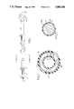
- FIG. 1 is a plan view of a bipolar pacing lead according to the present invention.
- FIG. 2 is a cross sectional view of the lead of FIG. 1.
- FIG. 3 is a cross sectional view through one of the conductor wires used in a lead according to FIG. 1.
- FIG. 4 is a top plan view of a wire transport used in sputtering conductor wires.
- FIG. 5 is a side, cutaway view of an apparatus for sputtering conductor wires.
- FIG. 1 shows a plan view of a cardiac pacing lead according to the present invention.
- the pacing lead 10 includes a connector assembly at its proximal end, including a first conductive surface 12, a second conductive surface 14, and two insulative segments 16 and 18. Insulative segments 16 and 18 are each provided with a plurality of sealing rings 20.
- Extending from the connector assembly is an elongated lead body, including an outer insulative sheath 22, which is preferably fabricated of polyurethane. Appropriate polyurethanes include Pellethane 80A and Pellethane 55D, both products of Dow Chemical Co.
- Within insulative sheath 22 is located a quadrifilar, multiconductor coil.
- FIG. 1 Two of the conductors within the coil are coupled to conductive surface 12. The other two are coupled to conductive surface 14.
- the conductor wires described herein may also be used advantageously in unipolar leads and in leads employing coils having three or more mutually insulated conductors.
- a ring electrode 24 coupled to two of the conductors, and a tip electrode 26, coupled to the other two of the four conductors of the quadrifilar coil.
- Extending between ring electrode 24 and tip electrode 26 is an additional polyurethane sheath 28. Fixation of the electrode within the heart is assisted by a plurality of flexible tines 30, as described in U.S. Pat. No. 3,902,501, issued to Citron et al.
- Tines 30 may be fabricated of polyurethane or silicone rubber.
- FIG. 2 shows a cross section through the lead of FIG. 1, intermediate the connector assembly and the ring electrode 24.
- the quadrifilar coil within sheath 22 is visible.
- This coil consists of four individual conductors 32A, B, C and D.
- the multifilar coil is provided with an internal lumen 26, which allows for the passage of a stylet.
- a Teflon® plastic liner 27 within lumen 26 may be provided to protect conductors 32A, B, C and D from nicks that might otherwise occur due to passage of the stylet.
- FIG. 3 shows a cross section of one of the individual conductors of the coil, 32A.
- Conductor 32A consists essentially of a core 28 fabricated of an alloy such as MP35N or Elgiloy® alloy or fabricated of DBS.
- the outer surface of conductor 32A is coated with a thin coating of an insulative, flexible polymer 38.
- Polymer coating 38 is preferably Tefzel® fluorocarbon coating manufactured by Dupont. Coating 38 is preferably applied using an extrusion process.
- Other appropriate insulative coatings, including Teflon®, plastic, polyurethanes and polyamids, may also be used.
- Intermediate coating 38 and core 36 is a thin layer 34 of an inert body compatible metal, free of cobalt, molybdenum and other materials which negatively interact with polyether urethanes.
- this layer consists of platinum, niobium, tantalum, titanium or alloys thereof, such as a platinum/niobium alloy.
- Other biocompatible metals, which are inert when in body fluids and in contact with polyurethanes may also be appropriate substitutes.
- An appropriate process for providing coating 34 is a sputtering process as set forth below. This process preferably is employed to provide a coating of between 300-500 ⁇ .
- FIG. 4 illustrates a top plan view of a wire transport apparatus useful for sputter coating conductor wire according to the present invention.
- Wire 102 is initially loaded onto payoff reel 110.
- Payoff reel 110 is provided with a drag 114 which maintains wire tension.
- the wire 102 then passes to idler pulley 116, through wire guide 120 and then onto grooved spool 124.
- the wire 102 is wound between the grooved spools 124 and 128 so that it makes a plurality of passes across the process area 130.
- the wire transport mechanism allows for much more rapid processing of the wire than would a single pass system.
- the wire 102 comes off of grooved spool 128 and passes through wire guide 138 to the idler pulley 142 and then to level winder 146.
- the level winder 146 is operated by means of cylindrical cam 147.
- the wire is taken up by the take-up spool 148 which is motor driven.
- the take-up spool 148 is conductive, but insulated from the rest of the wire transport, as is wire 102.
- a negative bias may be applied to take-up spool 148 by means of contact 154.
- the transport of FIG. 4 is intended for use with a sputtering cathode mounted horizontally above the process area 130.
- the arrangement of the transport mechanism may vary from that shown.
- the grooved spools 124 and 128 may be mounted vertically and the magnetron cathode and anode also mounted vertically. This alternative arrangement allows for the use of two cathodes, one on either side of the grooved spools.
- sputtering of two or more wires simultaneously may be accomplished. Regardless of the specific configuration chosen, it is important that the wire's path does not include any bends or exposure to sharp edges which would damage the wire or alter its mechanical properties. It is desirable to employ a tension monitor along the wire path in order to detect breaks or other malfunctions of the wire transport system.
- the tension monitor 150 is coupled to idler pulley 142.
- FIG. 4 is intended only as one example of a usable wire transport system.
- Other systems such as that illustrated in PCT Patent Application PCT/GB84/00246, International Publication No. WO85/00462, might also be utilized.
- FIG. 5 is a side, cutaway view of the assembled apparatus for sputtering conductor wire.
- the illustrated device employs a magnetron sputtering process, in which plasma of an inert gas, such as argon, is generated by means of an electric field.
- the apparatus employs a bias sputtering technique in which the wire conductor may be held at a negative potential relative to the vacuum chamber and plasma.
- This application also discloses alternative methods of wire coating which may also be advantageously employed in providing an inert metal coating on a conductor according to the present invention. These methods include RF sputtering, evaporative coating, activated evaporation, ion plating, and plasma assisted chemical vapor deposition.
- the apparatus illustrated in FIG. 5 is adapted for batch sputtering of wire conductor, and includes a vacuum chamber 100 which contains the complete wire transport mechanism 101.
- a vacuum chamber 100 which contains the complete wire transport mechanism 101.
- the criss-cross pattern of wire 102 intermediate the grooved spools 124 and 128 is visible.
- Shaft 104 which drives take-up reel 148 is also visible.
- the magnetron cathode 132 and anode 134 are mounted to the removable top 140 of vacuum chamber 100. Cooling lines 150, 152 and power cable 160 are routed to the magnetron cathode 132 via housing 162.
- a 4 inch D.C. magnetron cathode, Type C manufactured by Vac-Tec Systems is used.
- the wire 102 should pass within 3 or 4 inches of the cathode 132.
- the target which comprises the metal to be sputtered is mounted to cathode 132.
- Vacuum is applied to the chamber by means of vacuum port 156.
- Argon gas is supplied to the chamber by means of gas port 158.
- the thickness of the coating provided by the apparatus of FIG. 5 is dictated by a combination of factors, including distance to target, argon gas pressure, wire speed, number of passes and magnetron power setting. In general, it has been found that a coating rate of approximately 1000 Angstroms per minute provides an adequate coating. However, other coating rates may be used. Preferably, a layer of about 500 ⁇ or less is deposited.
- the apparatus illustrated in FIG. 5 is useful in depositing platinum, tantalum, niobium and titanium, as well as other materials.
- the general operation of the device of FIG. 5 to provide a sputtered platinum coating on MP35N alloy or DBS wire of about 0.1 to 3 mm in diameter is as follows. After loading the wire onto the wire transport system, the vacuum chamber 100 is evacuated to about 5 ⁇ 10 -7 Torr and the cooling system for the magnetron cathode 132 is activated. After pressure has stabilized, argon gas is admitted via gas port 158, with gas pressure in the chamber regulated to about 2 milliTorr. The magnetron 132 is then activated in its DC mode, and adjusted to a power output of approximately 0.5 kilowatts. After the power level stabilizes, the motor driving take-up reel 148 is activated, and a negative bias may be applied to take-up reel 148. Bias voltages from 0 to negative 100 volts result in satisfactory coatings. Wire transport speed should be adjusted to provide the desired coating thickness. These parameters will of course vary depending upon the number, type, and arrangement of sputtering cathodes employed.
- One satisfactory method of cleaning the wire is to sequentially pass the wire through cleaning baths such as trichloroethane, isopropyl alcohol, a mild alkali based detergent solution, de-ionized water, isopropyl alcohol and freon, in that order.
- the solvents may be contained in ultrasonic cleaners, with the exception of the freon.
- the wire should stay immersed in each solvent for long enough to assure thorough cleaning. A time of 2-3 minutes has been found to be adequate. Vapor degreasing systems such as disclosed in the above-cited PCT application are also believed appropriate.
- the coated wire When used in leads having multiconductor coils, it is expected that at least some of the wires will be provided with a layer of insulating material in order to provide electrical isolation of the individual conductors in the coil.
- the coated wire may be used without an insulative layer. In either embodiment, the metal coated wire provides significant advantages. In embodiments not employing an outer insulative layer, niobium, tantalum and titanium are believed especially preferable.
- Conductor wires produced according to the present invention are believed particularly advantageous for use in cardiac pacing leads. Testing by the inventors has indicated that pacing leads employing polyurethane insulation and conductor wires coated using the process described above have a substantially increased resistance to oxidative degradation compared to similar leads having uncoated conductor wires. For this testing, the insulative layer was omitted.
- conductor wires are typically less than 0.25 mm in diameter, and are wound into extremely small diameter coils, having diameters of 3 mm, or less and typically 2 mm or less.
- winding of coil sizes appropriate for use in pacing leads causes the sputtered coating to develop small breaches or cracks.
- simply covering a high percentage of the surface area of the conductor provides substantial improvement in resistance to oxidative degradation of the polyurethane sheath.
- the inventors have determined that actual physical contact between the conductor and the polyurethane insulation is a significant factor in the oxidative degradation of the polyurethane insulation. Even in the absence of an insulative outer layer, the typical cracks and breaches in the sputtered coating due to winding are unlikely to produce significant areas of contact between the base metal of the coil and the polyurethane insulation.
- the specific embodiment disclosed in the present application is a cardiac pacing lead, the teaching of the application and the claims hereof are believed equally applicable to other implantable electrical leads, such as neurostimulation leads or leads employing electrical transducers.
- the polymer coating 38 may be dispensed with entirely.
Abstract
Description
Claims (6)
Priority Applications (8)
| Application Number | Priority Date | Filing Date | Title |
|---|---|---|---|
| US07/156,145 US4860446A (en) | 1988-02-16 | 1988-02-16 | Medical electrical lead and method of manufacture |
| CA000590480A CA1328907C (en) | 1988-02-16 | 1989-02-08 | Medical electrical lead and method of manufacture |
| AU29913/89A AU605081B2 (en) | 1988-02-16 | 1989-02-14 | Medical electrical lead and method of manufacture |
| EP89102604A EP0329112B1 (en) | 1988-02-16 | 1989-02-15 | Medical electrical lead and method of manufacture |
| DE68918129T DE68918129T2 (en) | 1988-02-16 | 1989-02-15 | Medical electrical conductor and process for its manufacture. |
| JP1035178A JPH01268566A (en) | 1988-02-16 | 1989-02-16 | Medical electric lead and production thereof |
| US07/354,656 US4947866A (en) | 1988-02-16 | 1989-05-19 | Medical electrical lead |
| US07/547,893 US5040544A (en) | 1988-02-16 | 1990-06-29 | Medical electrical lead and method of manufacture |
Applications Claiming Priority (1)
| Application Number | Priority Date | Filing Date | Title |
|---|---|---|---|
| US07/156,145 US4860446A (en) | 1988-02-16 | 1988-02-16 | Medical electrical lead and method of manufacture |
Related Child Applications (1)
| Application Number | Title | Priority Date | Filing Date |
|---|---|---|---|
| US07/354,656 Division US4947866A (en) | 1988-02-16 | 1989-05-19 | Medical electrical lead |
Publications (1)
| Publication Number | Publication Date |
|---|---|
| US4860446A true US4860446A (en) | 1989-08-29 |
Family
ID=22558296
Family Applications (1)
| Application Number | Title | Priority Date | Filing Date |
|---|---|---|---|
| US07/156,145 Expired - Lifetime US4860446A (en) | 1988-02-16 | 1988-02-16 | Medical electrical lead and method of manufacture |
Country Status (6)
| Country | Link |
|---|---|
| US (1) | US4860446A (en) |
| EP (1) | EP0329112B1 (en) |
| JP (1) | JPH01268566A (en) |
| AU (1) | AU605081B2 (en) |
| CA (1) | CA1328907C (en) |
| DE (1) | DE68918129T2 (en) |
Cited By (40)
| Publication number | Priority date | Publication date | Assignee | Title |
|---|---|---|---|---|
| US5411545A (en) * | 1994-03-14 | 1995-05-02 | Medtronic, Inc. | Medical electrical lead |
| US5423881A (en) * | 1994-03-14 | 1995-06-13 | Medtronic, Inc. | Medical electrical lead |
| US5443491A (en) * | 1991-12-16 | 1995-08-22 | M.E.D.I.C.O. Italia S.R.L. | Three-pole electrocatheter |
| US5477864A (en) * | 1989-12-21 | 1995-12-26 | Smith & Nephew Richards, Inc. | Cardiovascular guidewire of enhanced biocompatibility |
| US5483022A (en) * | 1994-04-12 | 1996-01-09 | Ventritex, Inc. | Implantable conductor coil formed from cabled composite wire |
| US5607463A (en) * | 1993-03-30 | 1997-03-04 | Medtronic, Inc. | Intravascular medical device |
| US5760341A (en) * | 1996-09-10 | 1998-06-02 | Medtronic, Inc. | Conductor cable for biomedical lead |
| US5796044A (en) * | 1997-02-10 | 1998-08-18 | Medtronic, Inc. | Coiled wire conductor insulation for biomedical lead |
| US5849031A (en) * | 1997-12-16 | 1998-12-15 | Medtronic, Inc. | Method and apparatus for termination of tachyarrhythmias |
| US20030032997A1 (en) * | 2001-08-10 | 2003-02-13 | Pianca Anne M. | Low impedance high strength medical electrical lead |
| US20040055776A1 (en) * | 2000-06-27 | 2004-03-25 | Zoran Milijasevic | Stretchable conducting lead |
| US20040078070A1 (en) * | 2001-06-28 | 2004-04-22 | Medtronic, Inc. | Law impedance implantable extension for a neurological electrical stimulator |
| US20050060014A1 (en) * | 2001-08-31 | 2005-03-17 | Medtronic, Inc. | Implantable medical electrical stimulation lead fixation method and apparatus |
| US20070100411A1 (en) * | 2005-10-27 | 2007-05-03 | Medtronic, Inc. | Implantable medical electrical stimulation lead fixation method and apparatus |
| US20070132532A1 (en) * | 2004-04-01 | 2007-06-14 | Abb Technology Ag | Winding for a transformer or a coil and method for the production thereof |
| US20070142890A1 (en) * | 2005-12-19 | 2007-06-21 | Cardiac Pacemakers, Inc. | Interconnections of implantable lead conductors and electrodes and reinforcement therefor |
| US20070154729A1 (en) * | 2005-11-10 | 2007-07-05 | Cardiac Pacemakers, Inc. | Composite wire for implantable cardiac lead conductor cable and coils |
| US20080060832A1 (en) * | 2006-08-28 | 2008-03-13 | Ali Razavi | Multi-layer cable design and method of manufacture |
| US20080183260A1 (en) * | 2007-01-31 | 2008-07-31 | Nygren Lea A | Medical electrode including an iridium oxide surface and methods of fabrication |
| US20100137963A1 (en) * | 2005-01-25 | 2010-06-03 | Medtronic, Inc. | Method for fabrication of low-polarization implantable stimulation electrode |
| US20110224681A1 (en) * | 2010-03-15 | 2011-09-15 | Boston Scientific Neuromodulation Corporation | System and method for making and using a splitable lead introducer for an implantable electrical stimulation system |
| US20180243556A1 (en) * | 2005-06-30 | 2018-08-30 | Aionx Antimicrobial Technologies, Inc. | Prophylactic bactericidal medical device |
| US10682431B2 (en) | 2006-12-28 | 2020-06-16 | Aionx Antimicrobial Technologies, Inc. | Ex vivo antimicrobial devices and methods |
| US10850104B2 (en) | 2015-07-10 | 2020-12-01 | Axonics Modulation Technologies, Inc. | Implantable nerve stimulator having internal electronics without ASIC and methods of use |
| US10971950B2 (en) | 2013-07-29 | 2021-04-06 | The Alfred E. Mann Foundation For Scientific Research | Microprocessor controlled class E driver |
| US11083903B2 (en) | 2016-01-29 | 2021-08-10 | Axonics, Inc. | Methods and systems for frequency adjustment to optimize charging of implantable neurostimulator |
| US11110283B2 (en) | 2018-02-22 | 2021-09-07 | Axonics, Inc. | Neurostimulation leads for trial nerve stimulation and methods of use |
| US11116985B2 (en) | 2014-08-15 | 2021-09-14 | Axonics, Inc. | Clinician programmer for use with an implantable neurostimulation lead |
| US11123569B2 (en) | 2015-01-09 | 2021-09-21 | Axonics, Inc. | Patient remote and associated methods of use with a nerve stimulation system |
| US11213675B2 (en) | 2014-08-15 | 2022-01-04 | Axonics, Inc. | Implantable lead affixation structure for nerve stimulation to alleviate bladder dysfunction and other indication |
| US11260236B2 (en) | 2016-02-12 | 2022-03-01 | Axonics, Inc. | External pulse generator device and affixation device for trial nerve stimulation and methods of use |
| US11338144B2 (en) | 2013-03-15 | 2022-05-24 | Alfred E. Mann Foundation For Scientific Research | Current sensing multiple output current stimulators |
| US11389659B2 (en) | 2014-08-15 | 2022-07-19 | Axonics, Inc. | External pulse generator device and associated methods for trial nerve stimulation |
| US11439829B2 (en) | 2019-05-24 | 2022-09-13 | Axonics, Inc. | Clinician programmer methods and systems for maintaining target operating temperatures |
| US11478648B2 (en) | 2015-01-09 | 2022-10-25 | Axonics, Inc. | Antenna and methods of use for an implantable nerve stimulator |
| US11484723B2 (en) | 2015-01-09 | 2022-11-01 | Axonics, Inc. | Attachment devices and associated methods of use with a nerve stimulation charging device |
| US11497916B2 (en) | 2014-08-15 | 2022-11-15 | Axonics, Inc. | Electromyographic lead positioning and stimulation titration in a nerve stimulation system for treatment of overactive bladder |
| US11642537B2 (en) | 2019-03-11 | 2023-05-09 | Axonics, Inc. | Charging device with off-center coil |
| US11730411B2 (en) | 2014-08-15 | 2023-08-22 | Axonics, Inc. | Methods for determining neurostimulation electrode configurations based on neural localization |
| US11848090B2 (en) | 2019-05-24 | 2023-12-19 | Axonics, Inc. | Trainer for a neurostimulator programmer and associated methods of use with a neurostimulation system |
Families Citing this family (17)
| Publication number | Priority date | Publication date | Assignee | Title |
|---|---|---|---|---|
| DE4112936A1 (en) * | 1990-04-17 | 1991-10-24 | Biotronik Mess & Therapieg | Electrode esp. for heart pacemaker - has non-conductive tip coated with conductive coating |
| US5109844A (en) * | 1990-10-11 | 1992-05-05 | Duke University | Retinal microstimulation |
| US5630839A (en) * | 1991-10-22 | 1997-05-20 | Pi Medical Corporation | Multi-electrode cochlear implant and method of manufacturing the same |
| FR2685640B1 (en) * | 1991-12-31 | 1998-04-10 | Ela Medical Sa | ENDOCARDIAC PROBE WITH FOLDABLE BARBULES. |
| DE4223152C1 (en) * | 1992-07-14 | 1993-10-21 | Sanol Arznei Schwarz Gmbh | Device and method for producing a micro connector element and electrical supply line with at least one micro connector element |
| US5466253A (en) * | 1993-04-27 | 1995-11-14 | Pacesetter, Inc. | Crush resistant multi-conductor lead body |
| US5555618A (en) * | 1993-10-12 | 1996-09-17 | Arrow International Investment Corp. | Method of making electrode-carrying catheter |
| US5800500A (en) * | 1995-08-18 | 1998-09-01 | Pi Medical Corporation | Cochlear implant with shape memory material and method for implanting the same |
| WO1998029055A2 (en) * | 1996-12-19 | 1998-07-09 | Medtronic, Inc. | Medical electrical lead |
| DE69838479T2 (en) * | 1997-05-08 | 2008-06-19 | Medtronic, Inc., Minneapolis | SEGMENTED POLYURETHANE BIOMATERIALS CONTAINING MEDICAL DEVICES |
| US6216045B1 (en) | 1999-04-26 | 2001-04-10 | Advanced Neuromodulation Systems, Inc. | Implantable lead and method of manufacture |
| US7395116B2 (en) * | 2004-08-19 | 2008-07-01 | Medtronic, Inc. | Lead body-to-connector transition zone |
| JP4731459B2 (en) * | 2006-12-27 | 2011-07-27 | 株式会社ニデック | Visual reproduction assist device |
| DE102009009558B4 (en) * | 2009-02-19 | 2013-08-29 | Heraeus Precious Metals Gmbh & Co. Kg | Wound tape as electrical conductor for stimulation electrodes |
| DE102009009557A1 (en) | 2009-02-19 | 2010-09-02 | W.C. Heraeus Gmbh | Electrically conductive materials, leads and cables for stimulation electrodes |
| DE102010056343A1 (en) | 2010-12-29 | 2012-07-05 | Von Ardenne Anlagentechnik Gmbh | Device for vacuum-thin film coating of rod- or tubular-shaped solid substrates, comprises magnetron as source for coating, where magnetron is aligned on destination and comprises target arranged in sequence starting from destination |
| US10898139B2 (en) | 2016-06-03 | 2021-01-26 | Biosense Webster (Israel) Ltd. | Spine construction for basket catheter |
Citations (8)
| Publication number | Priority date | Publication date | Assignee | Title |
|---|---|---|---|---|
| US3348854A (en) * | 1965-06-04 | 1967-10-24 | Marker | Toe iron for safety ski bindings |
| US3700489A (en) * | 1970-07-30 | 1972-10-24 | Ethicon Inc | Process for applying a thin coating of polytetrafluoroethylene |
| US3788329A (en) * | 1972-04-17 | 1974-01-29 | Medtronic Inc | Body implantable lead |
| US4355646A (en) * | 1980-11-26 | 1982-10-26 | Medtronic, Inc. | Transvenous defibrillating lead |
| EP0073881A2 (en) * | 1981-09-03 | 1983-03-16 | W.C. Heraeus GmbH | Lead for cardiac pacemaker electrodes |
| CA1146228A (en) * | 1979-08-23 | 1983-05-10 | James E. Upton | Multipolar pacing conductor |
| WO1985000462A1 (en) * | 1983-07-08 | 1985-01-31 | Raychem Limited | Wire and cable |
| US4722353A (en) * | 1985-09-16 | 1988-02-02 | Intermedics, Inc. | Stabilizer for implantable electrode |
Family Cites Families (6)
| Publication number | Priority date | Publication date | Assignee | Title |
|---|---|---|---|---|
| US4352360A (en) * | 1981-03-30 | 1982-10-05 | Medtronic, Inc. | Semiconductor low-threshhold electrode |
| DE8211641U1 (en) * | 1982-04-22 | 1985-09-12 | Siemens AG, 1000 Berlin und 8000 München | Multipole coaxial cable |
| CH662669A5 (en) * | 1984-04-09 | 1987-10-15 | Straumann Inst Ag | GUIDE DEVICE FOR AT LEAST PARTIAL INSERTION IN A HUMAN OR ANIMAL BODY, WITH A HELM AT LEAST MADE FROM A LADDER. |
| FR2587635B1 (en) * | 1985-09-20 | 1989-01-27 | Onera (Off Nat Aerospatiale) | PROCESS FOR OBTAINING AN ELONGATED ELEMENT (IN PARTICULAR TAPE OR WIRE) CONSISTING OF AN ALLOY, ELONGATED ELEMENT THUS OBTAINED AND APPLICATIONS THEREOF |
| US4735205A (en) * | 1986-02-24 | 1988-04-05 | Medtronic, Inc. | Method and apparatus including a sliding insulation lead for cardiac assistance |
| CA1305528C (en) * | 1986-03-11 | 1992-07-21 | Ross G. Baker, Jr. | Low threshold cardiac pacing electrodes |
-
1988
- 1988-02-16 US US07/156,145 patent/US4860446A/en not_active Expired - Lifetime
-
1989
- 1989-02-08 CA CA000590480A patent/CA1328907C/en not_active Expired - Fee Related
- 1989-02-14 AU AU29913/89A patent/AU605081B2/en not_active Ceased
- 1989-02-15 EP EP89102604A patent/EP0329112B1/en not_active Expired - Lifetime
- 1989-02-15 DE DE68918129T patent/DE68918129T2/en not_active Expired - Fee Related
- 1989-02-16 JP JP1035178A patent/JPH01268566A/en active Granted
Patent Citations (8)
| Publication number | Priority date | Publication date | Assignee | Title |
|---|---|---|---|---|
| US3348854A (en) * | 1965-06-04 | 1967-10-24 | Marker | Toe iron for safety ski bindings |
| US3700489A (en) * | 1970-07-30 | 1972-10-24 | Ethicon Inc | Process for applying a thin coating of polytetrafluoroethylene |
| US3788329A (en) * | 1972-04-17 | 1974-01-29 | Medtronic Inc | Body implantable lead |
| CA1146228A (en) * | 1979-08-23 | 1983-05-10 | James E. Upton | Multipolar pacing conductor |
| US4355646A (en) * | 1980-11-26 | 1982-10-26 | Medtronic, Inc. | Transvenous defibrillating lead |
| EP0073881A2 (en) * | 1981-09-03 | 1983-03-16 | W.C. Heraeus GmbH | Lead for cardiac pacemaker electrodes |
| WO1985000462A1 (en) * | 1983-07-08 | 1985-01-31 | Raychem Limited | Wire and cable |
| US4722353A (en) * | 1985-09-16 | 1988-02-02 | Intermedics, Inc. | Stabilizer for implantable electrode |
Non-Patent Citations (2)
| Title |
|---|
| Brochure entitled "Anomet Products--The Leader in Platinum Anode Technology", by Anomet Products. |
| Brochure entitled Anomet Products The Leader in Platinum Anode Technology , by Anomet Products. * |
Cited By (62)
| Publication number | Priority date | Publication date | Assignee | Title |
|---|---|---|---|---|
| US5477864A (en) * | 1989-12-21 | 1995-12-26 | Smith & Nephew Richards, Inc. | Cardiovascular guidewire of enhanced biocompatibility |
| US5443491A (en) * | 1991-12-16 | 1995-08-22 | M.E.D.I.C.O. Italia S.R.L. | Three-pole electrocatheter |
| US5607463A (en) * | 1993-03-30 | 1997-03-04 | Medtronic, Inc. | Intravascular medical device |
| US5423881A (en) * | 1994-03-14 | 1995-06-13 | Medtronic, Inc. | Medical electrical lead |
| WO1995024941A1 (en) * | 1994-03-14 | 1995-09-21 | Medtronic, Inc. | Medical electrical lead |
| US5411545A (en) * | 1994-03-14 | 1995-05-02 | Medtronic, Inc. | Medical electrical lead |
| US5483022A (en) * | 1994-04-12 | 1996-01-09 | Ventritex, Inc. | Implantable conductor coil formed from cabled composite wire |
| US5760341A (en) * | 1996-09-10 | 1998-06-02 | Medtronic, Inc. | Conductor cable for biomedical lead |
| US5796044A (en) * | 1997-02-10 | 1998-08-18 | Medtronic, Inc. | Coiled wire conductor insulation for biomedical lead |
| US5849031A (en) * | 1997-12-16 | 1998-12-15 | Medtronic, Inc. | Method and apparatus for termination of tachyarrhythmias |
| US20040055776A1 (en) * | 2000-06-27 | 2004-03-25 | Zoran Milijasevic | Stretchable conducting lead |
| US20040078070A1 (en) * | 2001-06-28 | 2004-04-22 | Medtronic, Inc. | Law impedance implantable extension for a neurological electrical stimulator |
| US6950709B2 (en) | 2001-06-28 | 2005-09-27 | Medtronic, Inc. | Low impedance implantable extension for a neurological electrical stimulator |
| US20030032997A1 (en) * | 2001-08-10 | 2003-02-13 | Pianca Anne M. | Low impedance high strength medical electrical lead |
| US8626314B2 (en) | 2001-08-31 | 2014-01-07 | Medtronic, Inc. | Implantable medical lead including a plurality of tine elements |
| US6999819B2 (en) | 2001-08-31 | 2006-02-14 | Medtronic, Inc. | Implantable medical electrical stimulation lead fixation method and apparatus |
| US20060129218A1 (en) * | 2001-08-31 | 2006-06-15 | Medtronic, Inc. | Implantable medical electrical stimulation lead fixation method and apparatus |
| US20070050004A1 (en) * | 2001-08-31 | 2007-03-01 | Medtronic, Inc. | Implantable medical lead including tine markers |
| US8036756B2 (en) | 2001-08-31 | 2011-10-11 | Medtronics Inc | Implantable medical electrical stimulation lead fixation method and apparatus |
| US8000805B2 (en) | 2001-08-31 | 2011-08-16 | Medtronic, Inc. | Implantable medical lead including tine markers |
| US7330764B2 (en) | 2001-08-31 | 2008-02-12 | Medtronic, Inc. | Implantable medical electrical stimulation lead fixation method and apparatus |
| US7912555B2 (en) | 2001-08-31 | 2011-03-22 | Medtronic, Inc. | Implantable medical electrical stimulation lead fixation method and apparatus |
| US20050060014A1 (en) * | 2001-08-31 | 2005-03-17 | Medtronic, Inc. | Implantable medical electrical stimulation lead fixation method and apparatus |
| US7477126B2 (en) | 2004-04-01 | 2009-01-13 | Abb Technology Ag | Winding for a transformer or a coil and method for the production thereof |
| US20070132532A1 (en) * | 2004-04-01 | 2007-06-14 | Abb Technology Ag | Winding for a transformer or a coil and method for the production thereof |
| US20100137963A1 (en) * | 2005-01-25 | 2010-06-03 | Medtronic, Inc. | Method for fabrication of low-polarization implantable stimulation electrode |
| US8155754B2 (en) | 2005-01-25 | 2012-04-10 | Medtronic, Inc. | Method for fabrication of low-polarization implantable stimulation electrode |
| US20180243556A1 (en) * | 2005-06-30 | 2018-08-30 | Aionx Antimicrobial Technologies, Inc. | Prophylactic bactericidal medical device |
| US20070100411A1 (en) * | 2005-10-27 | 2007-05-03 | Medtronic, Inc. | Implantable medical electrical stimulation lead fixation method and apparatus |
| US7612291B2 (en) | 2005-11-10 | 2009-11-03 | Cardiac Pacemakers, Inc. | Composite wire for implantable cardiac lead conductor cable and coils |
| US20100044076A1 (en) * | 2005-11-10 | 2010-02-25 | Chastain Stuart R | Composite wire for implantable cardiac lead conductor cable and coils |
| US20070154729A1 (en) * | 2005-11-10 | 2007-07-05 | Cardiac Pacemakers, Inc. | Composite wire for implantable cardiac lead conductor cable and coils |
| US20090222074A1 (en) * | 2005-12-19 | 2009-09-03 | Zarembo Paul E | Interconnections of implantable lead conductors and electrodes and reinforcement therefor |
| US7546165B2 (en) | 2005-12-19 | 2009-06-09 | Cardiac Pacemakers, Inc. | Interconnections of implantable lead conductors and electrodes and reinforcement therefor |
| US20070142890A1 (en) * | 2005-12-19 | 2007-06-21 | Cardiac Pacemakers, Inc. | Interconnections of implantable lead conductors and electrodes and reinforcement therefor |
| US8055354B2 (en) | 2005-12-19 | 2011-11-08 | Cardiac Pacemakers, Inc. | Interconnections of implantable lead conductors and electrodes and reinforcement therefor |
| US20080060832A1 (en) * | 2006-08-28 | 2008-03-13 | Ali Razavi | Multi-layer cable design and method of manufacture |
| US10682431B2 (en) | 2006-12-28 | 2020-06-16 | Aionx Antimicrobial Technologies, Inc. | Ex vivo antimicrobial devices and methods |
| US8996129B2 (en) * | 2007-01-31 | 2015-03-31 | Medtronic, Inc. | Medical electrode including an iridium oxide surface and methods of fabrication |
| US20080183260A1 (en) * | 2007-01-31 | 2008-07-31 | Nygren Lea A | Medical electrode including an iridium oxide surface and methods of fabrication |
| US20110224681A1 (en) * | 2010-03-15 | 2011-09-15 | Boston Scientific Neuromodulation Corporation | System and method for making and using a splitable lead introducer for an implantable electrical stimulation system |
| US11338144B2 (en) | 2013-03-15 | 2022-05-24 | Alfred E. Mann Foundation For Scientific Research | Current sensing multiple output current stimulators |
| US10971950B2 (en) | 2013-07-29 | 2021-04-06 | The Alfred E. Mann Foundation For Scientific Research | Microprocessor controlled class E driver |
| US11722007B2 (en) | 2013-07-29 | 2023-08-08 | The Alfred E. Mann Foundation For Scientific Rsrch | Microprocessor controlled class E driver |
| US11730411B2 (en) | 2014-08-15 | 2023-08-22 | Axonics, Inc. | Methods for determining neurostimulation electrode configurations based on neural localization |
| US11497916B2 (en) | 2014-08-15 | 2022-11-15 | Axonics, Inc. | Electromyographic lead positioning and stimulation titration in a nerve stimulation system for treatment of overactive bladder |
| US11116985B2 (en) | 2014-08-15 | 2021-09-14 | Axonics, Inc. | Clinician programmer for use with an implantable neurostimulation lead |
| US11213675B2 (en) | 2014-08-15 | 2022-01-04 | Axonics, Inc. | Implantable lead affixation structure for nerve stimulation to alleviate bladder dysfunction and other indication |
| US11389659B2 (en) | 2014-08-15 | 2022-07-19 | Axonics, Inc. | External pulse generator device and associated methods for trial nerve stimulation |
| US11484723B2 (en) | 2015-01-09 | 2022-11-01 | Axonics, Inc. | Attachment devices and associated methods of use with a nerve stimulation charging device |
| US11478648B2 (en) | 2015-01-09 | 2022-10-25 | Axonics, Inc. | Antenna and methods of use for an implantable nerve stimulator |
| US11123569B2 (en) | 2015-01-09 | 2021-09-21 | Axonics, Inc. | Patient remote and associated methods of use with a nerve stimulation system |
| US10850104B2 (en) | 2015-07-10 | 2020-12-01 | Axonics Modulation Technologies, Inc. | Implantable nerve stimulator having internal electronics without ASIC and methods of use |
| US11766568B2 (en) | 2015-07-10 | 2023-09-26 | Axonics, Inc. | Implantable nerve stimulator having internal electronics without ASIC and methods of use |
| US11602638B2 (en) | 2016-01-29 | 2023-03-14 | Axonics, Inc. | Methods and systems for frequency adjustment to optimize charging of implantable neurostimulator |
| US11083903B2 (en) | 2016-01-29 | 2021-08-10 | Axonics, Inc. | Methods and systems for frequency adjustment to optimize charging of implantable neurostimulator |
| US11260236B2 (en) | 2016-02-12 | 2022-03-01 | Axonics, Inc. | External pulse generator device and affixation device for trial nerve stimulation and methods of use |
| US11110283B2 (en) | 2018-02-22 | 2021-09-07 | Axonics, Inc. | Neurostimulation leads for trial nerve stimulation and methods of use |
| US11511122B2 (en) | 2018-02-22 | 2022-11-29 | Axonics, Inc. | Neurostimulation leads for trial nerve stimulation and methods of use |
| US11642537B2 (en) | 2019-03-11 | 2023-05-09 | Axonics, Inc. | Charging device with off-center coil |
| US11439829B2 (en) | 2019-05-24 | 2022-09-13 | Axonics, Inc. | Clinician programmer methods and systems for maintaining target operating temperatures |
| US11848090B2 (en) | 2019-05-24 | 2023-12-19 | Axonics, Inc. | Trainer for a neurostimulator programmer and associated methods of use with a neurostimulation system |
Also Published As
| Publication number | Publication date |
|---|---|
| DE68918129T2 (en) | 1995-01-12 |
| EP0329112A1 (en) | 1989-08-23 |
| JPH0470912B2 (en) | 1992-11-12 |
| EP0329112B1 (en) | 1994-09-14 |
| JPH01268566A (en) | 1989-10-26 |
| CA1328907C (en) | 1994-04-26 |
| AU605081B2 (en) | 1991-01-03 |
| AU2991389A (en) | 1989-08-17 |
| DE68918129D1 (en) | 1994-10-20 |
Similar Documents
| Publication | Publication Date | Title |
|---|---|---|
| US4860446A (en) | Medical electrical lead and method of manufacture | |
| US5040544A (en) | Medical electrical lead and method of manufacture | |
| US4947866A (en) | Medical electrical lead | |
| US5423881A (en) | Medical electrical lead | |
| US5534022A (en) | Lead having an integrated defibrillation/sensing electrode | |
| US5796044A (en) | Coiled wire conductor insulation for biomedical lead | |
| US10086189B2 (en) | Medical electrical lead | |
| US7337009B2 (en) | Lead having composite tubing | |
| US5016808A (en) | Implantable tapered spiral endocardial lead for use in internal defibrillation | |
| US4711027A (en) | Implantable lead construction | |
| EP0681494B1 (en) | An implantable electrode | |
| US20060293737A1 (en) | Multiple electrode implantable lead | |
| EP2044972B1 (en) | Implantable medical device lead conductor | |
| JP2006501028A (en) | Cardiac vein lead having a flexible anode and method of manufacturing the same | |
| US7184839B2 (en) | Catheter-delivered cardiac lead | |
| EP1133332A1 (en) | Low profile, ventricular, transvenous, epicardial defibrillation lead | |
| US5433744A (en) | Medical electrical lead with super austentic stainless steel conductor | |
| Mond et al. | Implantable transvenous pacing leads: the shape of things to come | |
| US6606522B2 (en) | Torque mechanism and method for endocardial leads | |
| US20100318019A1 (en) | Electrophysiology devices employing electrically conductive polymer conductors and methods of manufacturing such devices | |
| US5411545A (en) | Medical electrical lead | |
| US20210102309A1 (en) | Electropolishing of mp35n wire for fatigue life improvement of an implantable lead |
Legal Events
| Date | Code | Title | Description |
|---|---|---|---|
| AS | Assignment |
Owner name: MEDTRONIC, INC., 7000 CENTRAL AVENUEN N.E., MINNEA Free format text: ASSIGNMENT OF ASSIGNORS INTEREST.;ASSIGNORS:LESSAR, JOSEPH F.;ROSENBERG, DUANE L.;KRASKA, ROBERT E.;AND OTHERS;REEL/FRAME:004837/0711 Effective date: 19880211 Owner name: MEDTRONIC, INC., A CORP. OF MINNESOTA,MINNESOTA Free format text: ASSIGNMENT OF ASSIGNORS INTEREST;ASSIGNORS:LESSAR, JOSEPH F.;ROSENBERG, DUANE L.;KRASKA, ROBERT E.;AND OTHERS;REEL/FRAME:004837/0711 Effective date: 19880211 |
|
| STCF | Information on status: patent grant |
Free format text: PATENTED CASE |
|
| FEPP | Fee payment procedure |
Free format text: PAYOR NUMBER ASSIGNED (ORIGINAL EVENT CODE: ASPN); ENTITY STATUS OF PATENT OWNER: LARGE ENTITY |
|
| FPAY | Fee payment |
Year of fee payment: 4 |
|
| FPAY | Fee payment |
Year of fee payment: 8 |
|
| FPAY | Fee payment |
Year of fee payment: 12 |