US4859947A - Magnetic resonance imaging apparatus comprising a stacked surface coil system - Google Patents
Magnetic resonance imaging apparatus comprising a stacked surface coil system Download PDFInfo
- Publication number
- US4859947A US4859947A US07/117,003 US11700387A US4859947A US 4859947 A US4859947 A US 4859947A US 11700387 A US11700387 A US 11700387A US 4859947 A US4859947 A US 4859947A
- Authority
- US
- United States
- Prior art keywords
- coils
- magnetic resonance
- cascade
- imaging apparatus
- resonance imaging
- Prior art date
- Legal status (The legal status is an assumption and is not a legal conclusion. Google has not performed a legal analysis and makes no representation as to the accuracy of the status listed.)
- Expired - Lifetime
Links
Images
Classifications
-
- G—PHYSICS
- G01—MEASURING; TESTING
- G01N—INVESTIGATING OR ANALYSING MATERIALS BY DETERMINING THEIR CHEMICAL OR PHYSICAL PROPERTIES
- G01N24/00—Investigating or analyzing materials by the use of nuclear magnetic resonance, electron paramagnetic resonance or other spin effects
-
- G—PHYSICS
- G01—MEASURING; TESTING
- G01R—MEASURING ELECTRIC VARIABLES; MEASURING MAGNETIC VARIABLES
- G01R33/00—Arrangements or instruments for measuring magnetic variables
- G01R33/20—Arrangements or instruments for measuring magnetic variables involving magnetic resonance
- G01R33/28—Details of apparatus provided for in groups G01R33/44 - G01R33/64
- G01R33/32—Excitation or detection systems, e.g. using radio frequency signals
- G01R33/34—Constructional details, e.g. resonators, specially adapted to MR
- G01R33/341—Constructional details, e.g. resonators, specially adapted to MR comprising surface coils
- G01R33/3415—Constructional details, e.g. resonators, specially adapted to MR comprising surface coils comprising arrays of sub-coils, i.e. phased-array coils with flexible receiver channels
-
- G—PHYSICS
- G01—MEASURING; TESTING
- G01R—MEASURING ELECTRIC VARIABLES; MEASURING MAGNETIC VARIABLES
- G01R33/00—Arrangements or instruments for measuring magnetic variables
- G01R33/20—Arrangements or instruments for measuring magnetic variables involving magnetic resonance
- G01R33/28—Details of apparatus provided for in groups G01R33/44 - G01R33/64
- G01R33/32—Excitation or detection systems, e.g. using radio frequency signals
- G01R33/34—Constructional details, e.g. resonators, specially adapted to MR
- G01R33/341—Constructional details, e.g. resonators, specially adapted to MR comprising surface coils
Definitions
- the invention relates to a magnetic resonance imaging apparatus, comprising a magnet system for generating a steady magnetic field, a magnet system for generating gradient fields, an rf transmitter coil, and an rf surface coil system for detecting magnetic resonance signals to be generated in an object to be examined.
- An apparatus described therein is found to have a drawback in that, if the surface coil is constructed for a desired improved signal-to-noise ratio for the detection signals without displacement of the coil with respect to an object to be examined, only a comparatively small part of the object can be measured.
- a magnetic resonance apparatus of the kind set forth in accordance with the invention is characterized in that the rf surface coil system comprises a cascade of consecutive surface coils.
- the rf coil system in accordance with the invention comprises a plurality of consecutive coils, the attractive signal-to-noise ratio is maintained for each of the coils upon detection, so that a large object can still be completely measured by switching over to a next coil of the cascade.
- a coil system may comprise pairs of sets of coils to be symmetrically arranged about the object.
- the coils are accommodated, for example, in a flexible band which can be arranged around an object to be measured.
- one system may be rigidly connected to an object carrier and a second system may be arranged so as to be pivotable and displaceable in the carrier.
- the coils are preferably mounted so as to be curved to the extent possible to enable conformity with the shape of an object.
- the rf coil system comprises coils for measuring sagittal cross-sections and, due to the expiration of time between successive measurements for a cross-section, large differences could occur in the strength of the detection signals. This drawback can be avoided by using an adapted measuring method where each time parts of one and the same cross-section are measured.
- the rf coil system comprises a cascade of butterfly coils so that, when use is made of a uniform transmission field, each of the coils is already uncoupled by its geometry in respect of interference by the transmission field.
- each of the coils is already uncoupled by its geometry in respect of interference by the transmission field.
- the orientation in the transmission field is limited to preferred directions in order to maintain automatic uncoupling.
- FIG. 1 shows a magnetic resonance imaging apparatus comprising an rf coil system in accordance with the invention
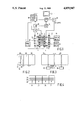
- FIGS. 2, 3 and 4 shows preferred embodiments of coil system for such an apparatus.
- a magnetic resonance imaging apparatus as shown in FIG. 1 comprises a magnet system 2 for generating a steady, uniform magnetic field, a magnet system 4 for generating magnetic gradient fields, and power supply sources 6 and 8 for the magnet system 2 and the magnet system 4, respectively.
- a magnet coil 10 for generating an rf magnetic alternating field is connected to an rf source 12.
- a surface coil 13 is provided for the detection of magnetic resonance signals generated by the rf transmission field in an object to be examined. For reading, the coil 13 is connected to a signal amplifier 14.
- the signal amplifier 14 is connected to a phase-sensitive rectifier 16 which is connected to a central control device 18.
- the central control device 18 also controls a modulator 20 for the rf source 12, the supply source 8 for the gradient coils, and a monitor 22 for display.
- An rf oscillator 24 controls the modulator 20 as well as the phase-sensitive rectifier 16 which processes the measurement signals.
- a cooling device 26 which comprises cooling ducts 27.
- a cooling device of this kind can be constructed as a water cooling system for resistance coils or as a liquid helium dewar system for superconducting coils.
- the transmitter coil 10 which is arranged within the magnet systems 2 and 4 encloses a measurement space 28 which offers sufficient room for a patient in the case of medical diagnostic apparatus.
- the measurement space 28 there can be generated a steady magnetic field, gradient fields for position selection of slices to be imaged, and a spatially uniform rf alternating field.
- the measurement space is shielded against interference fields by a Faraday cage 29.
- a cascade of surface coils 32 so that all cross-sections of the object, in as far as covered by the measurements space 28, can be measured with a suitable signal-to-noise ratio without any displacement of the object or coils being required.
- a cascade of for example three surface coils having a length dimension of, for example 20 cm thus enables measurement across the entire length of the measurement space.
- the coils of the cascade overlap in that direction over a distance of, for example approximately 5 cm.
- FIG. 2 shows successive coils 32 which overlap over a distance 1 of, for example 2 cm.
- a distance 1 of, for example 2 cm In addition to the uncoupling of the measurement coils, during the active period of a transmitter coil as described in EP 164164, it must also be ensured that no undesirable cross-talk occurs between coils of the cascade. If this requirement cannot be sufficiently satisfied by the geometry and mutual orientation, use can also be made of uncoupling method as disclosed in EP 164164.
- FIG. 3 shows a cascade of butterfly coils in accordance with the invention, the successive coils 32 being arranged so that a given overlap (1) occurs only for the wings.
- an uncoupling circuit 30 For active uncoupling, it is merely necessary to prevent any mutual influencing of the coils of the cascade itself; for this purpose there may be provided an uncoupling circuit 30.
- Such a sagittal coil configuration can also be composed of butterfly coils, in which case it may be desirable to omit the overlapping in a direction transversely of the previously mentioned direction in order to obtain an adapted geometry, for example when use is made of roof-shaped butterfly coils. Because parts of the hinges of the butterfly coils then overlap, it may be desirable to provide the aperture of the coils, that is to say the incoming and outgoing conductors, in another part of the coil.
- a feasible butterfly coil can also be formed by composing each of the wings from a separate conductor, having the same inductance L, and a common conductor in which there is included a capacitance for uncoupling the coil for transmission fields which load each of the wings to the same extent.
Abstract
Description
Claims (11)
Applications Claiming Priority (2)
| Application Number | Priority Date | Filing Date | Title |
|---|---|---|---|
| NL8603006 | 1986-11-27 | ||
| NL8603006A NL8603006A (en) | 1986-11-27 | 1986-11-27 | MAGNETIC RESONANCE DEVICE WITH STACKED SURFACE COIL SYSTEM. |
Related Child Applications (1)
| Application Number | Title | Priority Date | Filing Date |
|---|---|---|---|
| US07/339,030 Continuation-In-Part US4943775A (en) | 1986-11-27 | 1989-04-14 | Magnetic resonance apparatus with uncoupled rf coils |
Publications (1)
| Publication Number | Publication Date |
|---|---|
| US4859947A true US4859947A (en) | 1989-08-22 |
Family
ID=19848890
Family Applications (1)
| Application Number | Title | Priority Date | Filing Date |
|---|---|---|---|
| US07/117,003 Expired - Lifetime US4859947A (en) | 1986-11-27 | 1987-11-04 | Magnetic resonance imaging apparatus comprising a stacked surface coil system |
Country Status (8)
| Country | Link |
|---|---|
| US (1) | US4859947A (en) |
| EP (1) | EP0273484B1 (en) |
| JP (1) | JP2599404B2 (en) |
| KR (1) | KR880006540A (en) |
| CN (1) | CN87108042A (en) |
| DE (1) | DE3772020D1 (en) |
| FI (1) | FI875183A (en) |
| NL (1) | NL8603006A (en) |
Cited By (15)
| Publication number | Priority date | Publication date | Assignee | Title |
|---|---|---|---|---|
| US4943775A (en) * | 1986-11-27 | 1990-07-24 | U.S. Philips Corporation | Magnetic resonance apparatus with uncoupled rf coils |
| US4973907A (en) * | 1988-12-01 | 1990-11-27 | U.S. Philips Corporation | RF coil system having several surface coils |
| US5122749A (en) * | 1988-02-15 | 1992-06-16 | Yokagawa Medical Systems, Limited | Magnetic resonance imaging apparatus |
| US5144243A (en) * | 1990-02-14 | 1992-09-01 | Kabushiki Kaisha Toshiba | RF coil system for use in magnetic resonance imaging apparatus |
| US5143688A (en) * | 1988-06-15 | 1992-09-01 | National Research Development Corporation | Surface electrical coil structures |
| US5216367A (en) * | 1990-02-21 | 1993-06-01 | Kabushiki Kaisha Toshiba | MR imaging apparatus capable of automatically selecting multiple surface coils |
| US5243288A (en) * | 1990-07-18 | 1993-09-07 | Kabushiki Kaisha Toshiba | Multiple coil type magnetic resonance imaging system including filters with different passbands |
| US5272437A (en) * | 1990-06-08 | 1993-12-21 | U.S. Philips Corporation | RF coil system in a magnetic resonance imaging apparatus |
| US5416413A (en) * | 1992-08-13 | 1995-05-16 | U. S. Philips Corporation | Magnetic resonance examination apparatus comprising a coil system for MR mammography |
| US5548218A (en) * | 1995-10-19 | 1996-08-20 | North Shore University Hospital Research Corporation | Flexible RF coils for MRI system |
| US6534983B1 (en) | 2000-12-29 | 2003-03-18 | Ge Medical Systems Global Technology Company, Llc | Multi-channel phased array coils having minimum mutual inductance for magnetic resonance systems |
| US20060055410A1 (en) * | 2004-09-10 | 2006-03-16 | Pierre Berube | Transmitter loops in series for geophysical surveys |
| US20150077116A1 (en) * | 2009-09-21 | 2015-03-19 | Time Medical Holdings Company Limited | Superconductor RF Coil Array |
| US9513351B2 (en) | 2011-09-15 | 2016-12-06 | Siemens Aktiengesellschaft | Magnetic resonance coil with overlapping coil elements |
| US10520563B2 (en) | 2015-09-29 | 2019-12-31 | Siemens Healthcare Gmbh | Adaptive MR local coil |
Families Citing this family (10)
| Publication number | Priority date | Publication date | Assignee | Title |
|---|---|---|---|---|
| NL8801018A (en) * | 1988-04-20 | 1989-11-16 | Philips Nv | MAGNETIC RESONANCE DEVICE WITH DISCONNECTED RF COILS. |
| EP0344293B1 (en) * | 1987-12-07 | 1995-03-15 | General Electric Company | Nuclear magnetic resonance (nmr) imaging with multiple surface coils |
| DE3816831A1 (en) * | 1988-05-18 | 1989-11-30 | Philips Patentverwaltung | CORE SPIN EXAMINATION DEVICE WITH A HIGH-FREQUENCY COIL ARRANGEMENT |
| DE3905564A1 (en) * | 1989-02-23 | 1990-09-06 | Philips Patentverwaltung | Arrangement for nuclear magnetic resonance (NMR, nuclear spin resonance) examination devices |
| US4975644A (en) * | 1989-03-29 | 1990-12-04 | Kabushiki Kaisha Toshiba | Coil system for a magnetic resonance imaging system |
| IL91805A (en) * | 1989-09-27 | 1996-12-05 | Elscint Ltd | Quadrature surface coil |
| DE19515586A1 (en) * | 1995-04-27 | 1996-10-31 | Siemens Ag | HF antenna system for medical NMR device for human body investigation |
| DE19616464A1 (en) * | 1996-04-25 | 1997-11-06 | Philips Patentverwaltung | MR device with a solenoid arrangement and a surface coil arrangement |
| DE102005039380B4 (en) * | 2005-08-19 | 2009-06-10 | Siemens Ag | Surface coil arrangement for magnetic resonance tomographs |
| JP4901917B2 (en) * | 2009-06-26 | 2012-03-21 | 中国電力株式会社 | Magnetic measurement device, nondestructive inspection device, and method of arranging detection coil of magnetic sensor |
Citations (6)
| Publication number | Priority date | Publication date | Assignee | Title |
|---|---|---|---|---|
| US4361807A (en) * | 1979-08-10 | 1982-11-30 | Picker International Limited | Nuclear magnetic resonance systems |
| US4398149A (en) * | 1981-02-02 | 1983-08-09 | Varian Associates, Inc. | NMR Probe coil system |
| US4592363A (en) * | 1983-11-08 | 1986-06-03 | Siemens Aktiengesellschaft | High-frequency device for nuclear spin resonance apparatus having a surface coil |
| US4616181A (en) * | 1982-10-12 | 1986-10-07 | U.S. Philips Corporation | Nuclear magnetic resonance tomography apparatus |
| US4636730A (en) * | 1984-08-16 | 1987-01-13 | General Electric Company | NMR spectroscopy body probes with at least one surface coil |
| US4652827A (en) * | 1984-03-10 | 1987-03-24 | Jeol Ltd. | Nuclear magnetic resonance spectrometer |
Family Cites Families (4)
| Publication number | Priority date | Publication date | Assignee | Title |
|---|---|---|---|---|
| JPS60125550A (en) * | 1983-12-12 | 1985-07-04 | Sanyo Electric Co Ltd | Rf coil for nmr-ct |
| NL8401671A (en) * | 1984-05-25 | 1985-12-16 | Philips Nv | NUCLEAR SPIN RESONANCE DEVICE WITH SURFACE COIL DETECTION. |
| US4620155A (en) * | 1984-08-16 | 1986-10-28 | General Electric Company | Nuclear magnetic resonance imaging antenna subsystem having a plurality of non-orthogonal surface coils |
| NL8502612A (en) * | 1985-09-25 | 1987-04-16 | Philips Nv | MAGNETIC RESONANCE DEVICE WITH DETACHING SURFACE COIL DETECTION. |
-
1986
- 1986-11-27 NL NL8603006A patent/NL8603006A/en not_active Application Discontinuation
-
1987
- 1987-11-04 US US07/117,003 patent/US4859947A/en not_active Expired - Lifetime
- 1987-11-24 EP EP87202301A patent/EP0273484B1/en not_active Expired - Lifetime
- 1987-11-24 FI FI875183A patent/FI875183A/en not_active IP Right Cessation
- 1987-11-24 CN CN198787108042A patent/CN87108042A/en active Pending
- 1987-11-24 JP JP62294276A patent/JP2599404B2/en not_active Expired - Lifetime
- 1987-11-24 DE DE8787202301T patent/DE3772020D1/en not_active Expired - Lifetime
- 1987-11-26 KR KR870013330A patent/KR880006540A/en not_active Application Discontinuation
Patent Citations (6)
| Publication number | Priority date | Publication date | Assignee | Title |
|---|---|---|---|---|
| US4361807A (en) * | 1979-08-10 | 1982-11-30 | Picker International Limited | Nuclear magnetic resonance systems |
| US4398149A (en) * | 1981-02-02 | 1983-08-09 | Varian Associates, Inc. | NMR Probe coil system |
| US4616181A (en) * | 1982-10-12 | 1986-10-07 | U.S. Philips Corporation | Nuclear magnetic resonance tomography apparatus |
| US4592363A (en) * | 1983-11-08 | 1986-06-03 | Siemens Aktiengesellschaft | High-frequency device for nuclear spin resonance apparatus having a surface coil |
| US4652827A (en) * | 1984-03-10 | 1987-03-24 | Jeol Ltd. | Nuclear magnetic resonance spectrometer |
| US4636730A (en) * | 1984-08-16 | 1987-01-13 | General Electric Company | NMR spectroscopy body probes with at least one surface coil |
Non-Patent Citations (2)
| Title |
|---|
| Japanese Patent Abstract, vol. 9, No. 285, p. 404 (11/12/85), "RF Coil for NMR-CT", Matsumoto. |
| Japanese Patent Abstract, vol. 9, No. 285, p. 404 (11/12/85), RF Coil for NMR CT , Matsumoto. * |
Cited By (19)
| Publication number | Priority date | Publication date | Assignee | Title |
|---|---|---|---|---|
| US4943775A (en) * | 1986-11-27 | 1990-07-24 | U.S. Philips Corporation | Magnetic resonance apparatus with uncoupled rf coils |
| US5122749A (en) * | 1988-02-15 | 1992-06-16 | Yokagawa Medical Systems, Limited | Magnetic resonance imaging apparatus |
| US5143688A (en) * | 1988-06-15 | 1992-09-01 | National Research Development Corporation | Surface electrical coil structures |
| US4973907A (en) * | 1988-12-01 | 1990-11-27 | U.S. Philips Corporation | RF coil system having several surface coils |
| US5144243A (en) * | 1990-02-14 | 1992-09-01 | Kabushiki Kaisha Toshiba | RF coil system for use in magnetic resonance imaging apparatus |
| US5216367A (en) * | 1990-02-21 | 1993-06-01 | Kabushiki Kaisha Toshiba | MR imaging apparatus capable of automatically selecting multiple surface coils |
| US5272437A (en) * | 1990-06-08 | 1993-12-21 | U.S. Philips Corporation | RF coil system in a magnetic resonance imaging apparatus |
| US5243288A (en) * | 1990-07-18 | 1993-09-07 | Kabushiki Kaisha Toshiba | Multiple coil type magnetic resonance imaging system including filters with different passbands |
| US5416413A (en) * | 1992-08-13 | 1995-05-16 | U. S. Philips Corporation | Magnetic resonance examination apparatus comprising a coil system for MR mammography |
| US5548218A (en) * | 1995-10-19 | 1996-08-20 | North Shore University Hospital Research Corporation | Flexible RF coils for MRI system |
| US6534983B1 (en) | 2000-12-29 | 2003-03-18 | Ge Medical Systems Global Technology Company, Llc | Multi-channel phased array coils having minimum mutual inductance for magnetic resonance systems |
| US20060055410A1 (en) * | 2004-09-10 | 2006-03-16 | Pierre Berube | Transmitter loops in series for geophysical surveys |
| WO2006026867A1 (en) * | 2004-09-10 | 2006-03-16 | Abitibi-Géophysique | Transmitter loops in series for geophysical surveys |
| US7116107B2 (en) | 2004-09-10 | 2006-10-03 | Abitibi Geophysics Inc. | Transmitter loops in series for electromagnetic geophysical surveys |
| AU2005204283B2 (en) * | 2004-09-10 | 2010-05-20 | Abitibi-Geophysique | Transmitter loops in series for geophysical surveys |
| AU2005204283B8 (en) * | 2004-09-10 | 2010-06-17 | Abitibi-Geophysique | Transmitter loops in series for geophysical surveys |
| US20150077116A1 (en) * | 2009-09-21 | 2015-03-19 | Time Medical Holdings Company Limited | Superconductor RF Coil Array |
| US9513351B2 (en) | 2011-09-15 | 2016-12-06 | Siemens Aktiengesellschaft | Magnetic resonance coil with overlapping coil elements |
| US10520563B2 (en) | 2015-09-29 | 2019-12-31 | Siemens Healthcare Gmbh | Adaptive MR local coil |
Also Published As
| Publication number | Publication date |
|---|---|
| JP2599404B2 (en) | 1997-04-09 |
| EP0273484A2 (en) | 1988-07-06 |
| FI875183A (en) | 1988-05-28 |
| EP0273484A3 (en) | 1988-07-20 |
| EP0273484B1 (en) | 1991-08-07 |
| JPS63234957A (en) | 1988-09-30 |
| DE3772020D1 (en) | 1991-09-12 |
| FI875183A0 (en) | 1987-11-24 |
| NL8603006A (en) | 1988-06-16 |
| CN87108042A (en) | 1988-06-08 |
| KR880006540A (en) | 1988-07-23 |
Similar Documents
| Publication | Publication Date | Title |
|---|---|---|
| US4859947A (en) | Magnetic resonance imaging apparatus comprising a stacked surface coil system | |
| EP0274773B1 (en) | Magnetic resonance imaging apparatus comprising a quadrature coil system | |
| US5610521A (en) | Gradient and RF coil system without RF shield | |
| US5592088A (en) | Multiple-coil adopting a quadrature detection method applied thereto and a signal processing circuit employing the same in an MRI apparatus in a vertical magnetic system | |
| US5898306A (en) | Single circuit ladder resonator quadrature surface RF coil | |
| US5416413A (en) | Magnetic resonance examination apparatus comprising a coil system for MR mammography | |
| US5144243A (en) | RF coil system for use in magnetic resonance imaging apparatus | |
| US6008649A (en) | RF coil apparatus for MR system with lateral B0 field | |
| US7061242B2 (en) | Magnetic resonance imaging system | |
| US4839595A (en) | Magnetic resonance apparatus with a decoupling detection surface coil | |
| US7123014B2 (en) | Magnetic gradient field projection | |
| EP0304126A1 (en) | Magnetic resonance apparatus comprising an improved gradient coil system | |
| KR890000605B1 (en) | Mri equipment | |
| JP2003180659A (en) | Rf coil system for magnetic resonance imaging device | |
| Zhang et al. | Active MR guidance of interventional devices with target‐navigation | |
| IL92510A (en) | Surface coil array receiver | |
| EP0529730B1 (en) | Magnetic resonance apparatus comprising decoupled receiver coils | |
| CN111913142A (en) | Basic field magnet arrangement, magnetic resonance tomography system and measuring method | |
| EP3828573A1 (en) | V-shaped gradient system for a magnetic resonance imaging system | |
| EP0815462B1 (en) | Combination circuit for an rf measuring coil system for detection of magnetic resonance signals | |
| EP0338624A1 (en) | Magnetic resonance apparatus with uncoupled rf coils | |
| US6668184B1 (en) | System for and method of synchronizing an image data receiver and an MR imaging acquisition slice | |
| WO2017191860A1 (en) | Magnetic resonance imaging system | |
| US6982553B2 (en) | Radio frequency coil with two parallel end conductors | |
| US20070096736A1 (en) | Mri rf surface coil with reduced sensitivity in proximity of conductors |
Legal Events
| Date | Code | Title | Description |
|---|---|---|---|
| AS | Assignment |
Owner name: U.S. PHILIPS CORPORATION, 100 EAST 42ND ST., NEW Y Free format text: ASSIGNMENT OF ASSIGNORS INTEREST.;ASSIGNOR:BOSKAMP, EDDY B.;REEL/FRAME:004824/0101 Effective date: 19871228 Owner name: U.S. PHILIPS CORPORATION, A CORP OF DE,NEW YORK Free format text: ASSIGNMENT OF ASSIGNORS INTEREST;ASSIGNOR:BOSKAMP, EDDY B.;REEL/FRAME:004824/0101 Effective date: 19871228 |
|
| STCF | Information on status: patent grant |
Free format text: PATENTED CASE |
|
| FEPP | Fee payment procedure |
Free format text: PAYOR NUMBER ASSIGNED (ORIGINAL EVENT CODE: ASPN); ENTITY STATUS OF PATENT OWNER: LARGE ENTITY |
|
| FPAY | Fee payment |
Year of fee payment: 4 |
|
| FPAY | Fee payment |
Year of fee payment: 8 |
|
| FPAY | Fee payment |
Year of fee payment: 12 |