US4856529A - Ultrasonic pulmonary artery catheter and method - Google Patents
Ultrasonic pulmonary artery catheter and method Download PDFInfo
- Publication number
- US4856529A US4856529A US07/011,615 US1161587A US4856529A US 4856529 A US4856529 A US 4856529A US 1161587 A US1161587 A US 1161587A US 4856529 A US4856529 A US 4856529A
- Authority
- US
- United States
- Prior art keywords
- tubular member
- catheter
- transducer
- vessel
- straightening
- Prior art date
- Legal status (The legal status is an assumption and is not a legal conclusion. Google has not performed a legal analysis and makes no representation as to the accuracy of the status listed.)
- Expired - Lifetime
Links
Images


Classifications
-
- A—HUMAN NECESSITIES
- A61—MEDICAL OR VETERINARY SCIENCE; HYGIENE
- A61B—DIAGNOSIS; SURGERY; IDENTIFICATION
- A61B8/00—Diagnosis using ultrasonic, sonic or infrasonic waves
- A61B8/06—Measuring blood flow
-
- A—HUMAN NECESSITIES
- A61—MEDICAL OR VETERINARY SCIENCE; HYGIENE
- A61B—DIAGNOSIS; SURGERY; IDENTIFICATION
- A61B8/00—Diagnosis using ultrasonic, sonic or infrasonic waves
- A61B8/12—Diagnosis using ultrasonic, sonic or infrasonic waves in body cavities or body tracts, e.g. by using catheters
-
- A—HUMAN NECESSITIES
- A61—MEDICAL OR VETERINARY SCIENCE; HYGIENE
- A61B—DIAGNOSIS; SURGERY; IDENTIFICATION
- A61B8/00—Diagnosis using ultrasonic, sonic or infrasonic waves
- A61B8/44—Constructional features of the ultrasonic, sonic or infrasonic diagnostic device
- A61B8/4444—Constructional features of the ultrasonic, sonic or infrasonic diagnostic device related to the probe
- A61B8/445—Details of catheter construction
-
- A—HUMAN NECESSITIES
- A61—MEDICAL OR VETERINARY SCIENCE; HYGIENE
- A61B—DIAGNOSIS; SURGERY; IDENTIFICATION
- A61B5/00—Measuring for diagnostic purposes; Identification of persons
- A61B5/68—Arrangements of detecting, measuring or recording means, e.g. sensors, in relation to patient
- A61B5/6846—Arrangements of detecting, measuring or recording means, e.g. sensors, in relation to patient specially adapted to be brought in contact with an internal body part, i.e. invasive
- A61B5/6847—Arrangements of detecting, measuring or recording means, e.g. sensors, in relation to patient specially adapted to be brought in contact with an internal body part, i.e. invasive mounted on an invasive device
- A61B5/6852—Catheters
- A61B5/6856—Catheters with a distal loop
Definitions
- This invention relates to ultrasonic arterial catheters and methods for use therein and, in particular, ultrasonic pulmonary artery catheters and methods adapted to be utilized for measuring instantaneous blood flow.
- Catheters have heretofore been utilized for making pressure measurements and for measuring cardiac output. Cardiac output in man typically has been ascertained by the Fick method, by a dye indicator dilution method and by a thermal indicator dilution method, none of which make possible the measurement of continuous instantaneous cardiac output. There is therefore a need for a new and improved catheter which can be utilized for measuring instantaneous blood flow in the pulmonary artery and other vessels.
- Another object of the invention is to provide a catheter and method of the above character which utilizes ultrasonic energy and in which it is possible to direct the ultrasonic energy in a blood vessel with substantial precision.
- Another object of the invention is to provide a catheter of the above character which is provided with a preformed shape which can be utilized to place an ultrasonic transducer in a position with respect to the wall of the blood vessel to provide aiming of the ultrasound beam through the fluid in the vessel.
- Another object of the invention is to provide a catheter and method of the above character in which it is possible to obtain ultrasonic beam penetration through a central axis of the vessel to thereby make it possible to obtain an accurate measurement of velocity and surface area.
- Another object of the invention is to provide a catheter and method of the above character which utilizes the Doppler principle for making instantaneous cardiac output measurements.
- Another object of the invention is to provide a catheter and method of the above character which makes it possible to accurately calculate the quantitative flow of blood through a blood vessel.
- Another object of the invention is to provide a catheter and method of the above character in which the precise orientation of the transducer with respect to blood flow in the vessel is known.
- Another object of the invention is to provide a catheter and method of the above character which makes it possible to positively ascertain when the transducer is located in the main pulmonary artery.
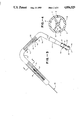
- FIG. 1 is a side elevational view of ultrasonic pulmonary artery catheter incorporating the present invention showing the same with the straightening wire retracted.
- FIG. 2 is a view similar to FIG. 1 but showing the catheter with the straightening wire extended.
- FIG. 3 is an enlarged portion of a distal extremity of the catheter shown in FIG. 1 with certain portions broken away.
- FIG. 4 is an enlarged cross sectional view taken along the line 4--4 of FIG. 3.
- FIG. 5 is a side elevational view of the straightening wire used in the catheter shown in FIG. 2.
- FIG. 6 is a diagrammatic illustration of the manner in which the catheter is utilized in a human heart to measure the quantitative blood flow through the pulmonary artery.
- FIG. 7 is an illustration showing the manner in which blood flow can be calculated utilizing a Doppler effect ultrasonic transducer in accordance with the present invention.
- FIG. 8 is another embodiment of the catheter incorporating the present invention which is shown in the earlier filed application Ser. No. 737,650, filed May 24, 1985.
- FIG. 9 is an enlarged cross-sectional view taken along the line 9--9 of FIG. 8.
- FIG. 10 is a side elevational view of still another embodiment of the catheter of the present invention which was shown in the earlier filed application Ser. No. 737,650, filed May 24, 1985.
- the catheter of the present invention is comprised of an elongate flexible tubular member or body having a plurality of lumens extending therethrough.
- the tubular member has proximal and distal extremities.
- An inflatable balloon is carried by the distal extremity of the tubular member and has its interior in communication with one of the lumens in the flexible tubular member.
- the tubular member is provided with a predetermined bend therein adjacent the distal extremity of the tubular member.
- a transducer is carried by the tubular member in the region of a predetermined bend.
- Conductive means is connected to the transducer and is carried by the tubular member and extends through one of the lumens in the tubular member to the proximal extremity of the tubular member.
- the tubular member has an opening in the distal extremity thereof distal of the balloon and in communication with one of the lumens in the tubular member
- the tubular member has an additional opening proximal of the balloon and in communication with another lumen in the tubular member.
- Means is carried by the tubular member for straightening the predetermined bend in the tubular member to facilitate insertion of the catheter into a vessel body having a liquid flowing therein.
- the catheter 11 of the present invention consists of a flexible elongate tubular member or body 12 formed of a suitable plastic such as polyurethane having a suitable outside diameter such as 0.090 inches and a length of approximately 50 to 100 centimeters and preferably approximately 90 centimeters.
- the distal extremity of the tubular member is of slightly reduced diameter of approximately 0.072 inches. This portion of reduced diameter has a suitable length as, for example, a length of 11/2 centimeters.
- the flexible elongate tubular member 12 is provided with a plurality of lumens extending therethrough and as shown, particularly in FIG. 4, namely lumens 13, 14, 16, 17 and 18.
- the lumen 13 can be identified as a straightening wire lumen.
- the lumen 14 can be identified as a transducer and a proximal pressure lumen and the lumen 16 can be identified as the distal pressure lumen.
- the lumen 17 can be identified as the balloon and transducer wire lumen and lumen 18 as the right ventricle pressure lumen. If desired, fewer or lesser lumens can be provided in the flexible elongate tubular member. Although the lumens 13, 14, 16, 17 and 18 all have been shown as having a predetermined configuration, it should be appreciated that different configurations of lumens can be utilized if desired.
- the flexible elongate member 12 is provided with proximal and distal extremities 21 and 22.
- the flexible elongate tubular member 12 is provided with one or more predetermined bends therein.
- predetermined bends 23 and 24 there are provided two predetermined bends 23 and 24.
- the bends 23 and 24 can subtend suitable angles, as for example, the bend 23 can subtend an angle of approximately 90°, whereas the bend 24 can subtend an angle of approximately 65°.
- the predetermined bends can be placed in the flexible tubular member 12 by placing in molds the portions of the flexible tubular member in which it is desired to place the bends and heating the molds to suitable temperature and then permitting the flexible elongate tubular member to cool within the molds so that the bends formed therein during heating are retained as the predetermined bends hereinbefore described.
- An inflatable balloon 26 is carried by the distal extremity 22 of the flexible elongate tubular member 12.
- the balloon 26 is formed of a suitable material such as a latex cylindrical sleeve having a wall thickness of approximately 0.001 inches and having proximal and distal extremities 27 and 28.
- the distal extremity 28 is secured to the exterior surface of the flexible tubular member 12 by suitable means such as an adhesive with the proximal extremity 27 extending forwardly of the tubular member 12.
- the proximal extremity 27 is the folded over the tubular member 12 as shown in FIG. 3 and then secured to the tubular member 12 by suitable means such as an adhesive.
- a hole or opening 31 is provided in the tubular member 12 and opens into the interior 32 of the balloon and also is in communication with the balloon inflation lumen 17.
- a tip 36 of a suitable relatively soft pliable plastic is secured to the distal extremity of the tubular member 12 by suitable means such as an adhesive.
- the tip 36 can be formed integral with the distal extremity of the tubular member 12 by extruding that portion of the tubular member 12 to a small diameter.
- the tip 36 is provided with an opening 37 which is in communication with the distal pressure lumen 16.
- An ultrasonic transducer 46 of a suitable conventional type such as one of lead titanate zirconate with silver electrodes is carried by the tubular member 12 and is of a size so that it can readily fit within the transducer and pulmonary artery pressure lumen 14.
- the ultrasonic transducer 46 is in the form of a relatively thin planar chip which is mounted at a predetermined angle, as for example, an angle of approximately 45° on an insulating block 48 of a suitable material such as an epoxy impregnated with tungsten oxide.
- the flexible elongate member 12 is provided with an elongate slot 49 opening into the transducer and pulmonary artery pressure lumen 14.
- the slot 49 makes it possible to insert the block 48 with the transducer carried thereby into the lumen 14 and to secure the same therein in a predetermined position, such as by means of an adhesive.
- Leads 51 and 52 are carried by the block 48 and are secured to the silver electrodes of the ultrasonic transducer 46.
- the leads 51 and 52 extend forwardly in the block 48 and are intertwined to provide an intertwined lead 53 which extends rearwardly from the block 48 and then through the balloon and transducer wire lumen 17.
- Another opening 56 is provided in the flexible elongate tubular member 12 proximal of the opening or slot 49 by a distance of approximately five centimeters and is in communication with the right ventricle pressure lumen 18. The distance of five centimeters should correspond approximately to the length of the main pulmonary artery in man.
- a manifold 61 of a suitable material such as plastic is mounted on the proximal extremity 21 of the tubular member 12.
- the manifold 61 carries a plurality of small elongate tubular members 62, 63, 64, 66 and 68.
- the distal extremities of the members 62, 63, 64 and 66 are inserted into the lumens 14, 16, 17 and 18, respectively and are sealed therein and also molded into the manifold 61.
- Luer-type fittings 67 are also provided on the proximal extremities of the members 62, 63, 64 and 66.
- Elongate tubular member 64 containing intertwined wires 53 branches into tubular member 68 which carries the wires 53.
- the wires 53 are connected to an electrical connector 69 mounted onto the proximal extremity of the tubular member 68.
- a rigid tubular sleeve 71 has its distal extremity mounted within the manifold 61 and has a flow passage 72 extending therethrough in communication with the central lumen 13 in the tubular member 12.
- the sleeve 71 can be formed of a suitable material of stainless steel and can have a suitable length such as approximately 10 centimeters.
- a fitting 76 is carried by the proximal extremity of the sleeve 71 and is provided with a flow passage 77 in communication with the passage 72.
- An O-ring 78 is seated in the fitting 76 and is adapted to be engaged by a threaded boss 79 threadedly mounted in the fitting 76.
- the boss 79 is provided with a knurled knob 81 to facilitate rotation of the same.
- the boss 79 and the knob 81 are provided with a bore 82 extending therethrough which is in communication with the flow passage 77.
- a straightening wire or pliable filament 86 is provided for use with the catheter 11 shown in FIGS. 1, 2 and 3 and consists of a core wire 87 formed of a suitable material such as stainless steel and having a suitable length, as for example, 120 centimeters. It can have a suitable diameter as, for example, 0.014 inches. If desired, a larger diameter core wire can be utilized.
- the core wire 87 is provided with proximal and distal extremities 88 and 89.
- the distal extremity 89 is provided with multiple tapers to provide increased flexibility for the distal extremity.
- a tapered portion 89a can be provided in which the diameter is reduced from 0.014 inches to 0.008 inches. Also provided is a straight cylindrical portion 89b of a length of approximately 1 centimeter and a diameter of 0.008 inches, a tapered portion 89c in which the diameter is reduced from 0.008 inches to 0.003 inches and a flattened portion 89d having a width of approximately 0.003 inches and a thickness of approximately 0.001 inches. The portion 89d terminates in a rounded protrusion 91 formed of a suitable material such as a tin silver solder.
- the protrusion 91 is also bonded to the distal extremity 92 of a coil spring 93.
- the proximal extremity 94 of the coil spring 93 is secured to the cylindrical portion 89b of the tapered portion 89 by suitable means such as solder 96.
- the coil spring can be formed of a suitable material such as stainless steel spring wire having a diameter of 0.01 inches and in which the outside diameter of the coil has a suitable diameter as, for example, 0.0012 inches.
- the proximal extremity 88 of the core wire 87 extends through a rigid hypodermic tube 101 of a suitable diameter such as 0.005 inches and having a length of approximately 10 centimeters.
- the proximal extremity of the hypodermic tube 101 and of the core wire 87 is secured to a knob 102.
- a mechanical stop in the form of a sleeve formed of suitable material such as a rubber material is provided on the distal extremity of the hypodermic tube 101 and engages the boss 79 to prevent retraction of the straightening wire 86.
- the straightening wire 86 is adapted to be advanced through the straightening wire lumen 13 for straightening the catheter 11 as hereinafter described.
- the distal extremity of the catheter 11 is straightened by grasping the knob 102 and pushing the same to advance the straightening wire into the bends 23 and 24 while pulling gently on the distal extremity of the catheter.
- the distal extremity of the straightening wire 87 readily negotiates these bends because of the relatively flexible spring tip provided on the straightening wire and also because of the fact that a rounded protrusion 91 is carried by the distal extremity of the spring.
- Great flexibility is provided by the various tapers provided in the distal extremity 89 of the straightening wire 87. As the flexible distal extremity negotiates the turns, the stiffer portions of the straightening wire enter the bends 23 and 24 to straighten them so that the catheter 11 assumes the general conformation as shown in FIG. 2.
- the catheter in the conformation shown in FIG. 2, the catheter can be readily inserted into the appropriate vessel into the patient and advanced in a conventional manner into the desired position in the patient's vessel.
- the catheter 11 is connected to appropriate monitoring equipment (not shown).
- the catheter 11 is then introduced by percutaneous technique through a suitable needle or sheath.
- the catheter is gently advanced until its tip has been advanced into the superior or inferior vena cava or the right atrium 111 as shown in FIG. 6.
- the balloon 26 is inflated to an appropriate volume as, for example, 1.5 cc by the use of a suitable gas such as carbon dioxide.
- a suitable gas such as carbon dioxide.
- the balloon will travel through the right atrium 111 of the patient's heart 112 (see FIG. 6).
- Pulmonary artery pressures will be observed as soon as the balloon and transducer lumen slot 49 passes through the pulmonic valve 115.
- the catheter 11 is permitted to be advanced with the balloon 26 inflated until the distal pressure lumen indicates that pulmonary capillary wedge position has been reached.
- pulmonary capillary wedge pressure, pulmonary artery pressure and right ventricular pressures can be ascertained using the distal, transducer, and right ventricular pressure lumens, 14, 16, and 18, respectively.
- the balloon 26 can be deflated by withdrawing the carbon dioxide and the catheter can be slowly withdrawn towards a previously recorded transition point until a right ventricular pressure trace appears via the right ventricular lumen 18 and a pulmonary artery pressure trace appears via the transducer lumen 14. This procedure confirms the position of the transducer within the main pulmonary artery. Placement of the transducer 46 in the main pulmonary artery 116 is critical for measurement of total cardiac output since the entire cardiac output is ejected only through the main pulmonary artery 116.
- transducer 46 and transducer slot 49 advance beyond the bifurcation to a branch 117 or 118 of the pulmonary artery, pulmonary artery waveforms will be observed, emanating from both slot 49 and hole 56, indicating that catheter 12 need be withdrawn slightly to place transducer 46 within the main pulmonary artery 116.
- the straightening wire 86 can be retracted by grasping the top of knob 102 and withdrawing tubing 101 and straightening wire 87 until the threaded boss 79 is reached.
- the boss 79 serves as a stop or abutment member when this has occurred, the straightening wire 86 is withdrawn from the bends 23 and 24 to permit the distal extremity of the catheter to assume its preformed shape in the manner shown in FIG. 6 in which that portion of the flexible elongate element 12 carrying the transducer 46 is positioned against the one wall of the pulmonary artery.
- Restoration of the shapes or conformation of the bends 23 and 24 in the elongate element 12 results in wedging of the transducer 46 tightly against one wall of the blood vessel.
- Circular symmetry of the cross section of the pulmonary artery 116 assures that transducer 46 is positioned so that it is facing in a direction which extends through the central flow axis of the pulmonary artery.
- the vessel diameter can be readily determined utilizing automatic diameter detection system of the type well known to those skilled in the art.
- Such systems which provide dynamic range-gating and diameter detection utilize Doppler shifted ultrasonic power within three sample gates such as one centered on the distal vessel wall, one near the vessel wall and one within the center of the vessel.
- a feedback loop adjusts gate positions so that reflected Doppler power from the far wall is a preset fraction of the Doppler power obtained from a sample volume located entirely within the central vessel lumen.
- the vessel diameter is then determined by continuously detecting the delay transit time to the far sample gate as it is adjusted to remain centered on the far wall.
- Instantaneous flow is calculated from the instantaneous space average velocity and instantaneous diameter using formulas well known to those skilled in the art.
- the balloon 26 may again be reinflated with the 0.15 cc of carbon dioxide in order to obtain simultaneous wedge pressure (via the distal lumen 16), pulmonary artery pressure (via the transducer lumen 14), right ventricular pressure (via the right ventricular lumen 18) and continuous cardiac output.
- the catheter can be removed by again reintroducing the straightening wire 86 into the bends 23 and 24 to substantially straighten the distal extremity of the catheter. Thereafter, the catheter can be removed by withdrawing it from the vessel of the patient.
- the catheter 11 has been preshaped to ensure a proper orientation of the ultrasonic transducer 46 which is carried by the distal extremity of the catheter 11.
- the preformed shape makes it possible to position the ultrasonic transducer 46 precisely within the blood vessel so that the ultrasound pulses emitted therefrom pass directly through the center of the vessel or lumen to make it possible to ensure accurate and continuous cardiac output monitoring.
- continuous pressure monitoring of precisely spaced transducer slot 49 and right ventricular hole 56 via transducer lumen 14 and right ventricular lumen 18 respectively assures that the transducer 46 is located within the main pulmonary artery such that accurate cardiac output can be measured.
- the straightening wire 86 can be retracted permitting the catheter, with its preformed distal extremity to properly orient itself in a stable position within the pulmonary artery and to at the same time, position the ultrasonic transducer 46 so that it emits pulses in a direction which pass diametrically through the vessel. Continuous cardiac output can then be displayed on an appropriate monitor (not shown).
- the catheter of the present invention makes it possible to obtain proper orientation of the ultrasonic transducer against a vessel wall with the ultrasonic pulses being emitted therefrom passing through a central diameter and longitudinal axis of the vessel to make it possible to obtain accurate measurements of velocity and surface area using the well-known Doppler principle. Since the angulation of the ultrasonic transducer to the catheter body and the blood vessel are known, accurate quantitative flow may be calculated.
- FIG. 8 An additional embodiment of a catheter 130 of the present invention is shown in FIG. 8 as described in pending application Ser. No. 737,650 filed on May 24, 1985.
- FIG. 9 is an enlarged cross-sectional view of catheter 130 taken along the line 9--9 of FIG. 8.
- This catheter 130 is comprised of a flexible elongate member or body 131 having a proximal end fitting 132 which has a number of ports, including two pressure ports 133 and 134.
- Pressure port 133 is coupled to an output tube 136 which is also coupled to port 137 and to a lumen 138 which is one of four lumens provided in the tubular elongate member or body 131.
- the lumen 138 opens to ambient through a hole 139 at its distal extremity in order to provide a pressure reading distal of a balloon 141.
- the distal extremity of the catheter tubular member 131 is preformed into an S-shaped curve 142 as indicated in FIG. 8.
- a Doppler crystal transducer 143 is located at the underside of the curve at approximately the apex thereof within a slot 144 opening into another lumen 146 in the element 131.
- the lumen 146 is coupled to the pressure port 134 permitting pressure monitoring of slot 144 in proximity of the transducer 143.
- a straightening or guide wire 147 which is provided with a knob 148 can be extended through lumen 138 from the port 137 to distal extremity of catheter in a manner previously described.
- the guide wire 147 as it is advanced through the lumen 138 serves to straighten out the S-curve 142 of the tubular member 131 for insertion into the vessel of the patient.
- the guide wire 147 must be of sufficient strength to straighten the catheter but of sufficient flexibility to allow for ease of insertion of the catheter.
- the balloon 141 can then be inflated through a lumen 149 connected to a port 150 to separate the two pressure holes 139 and 144 thereby blocking pressures from the right side of the heart and exposing hole 139 to pulmonary venous pressures which in turn reflect pressures on the left side of the heart while slot 144 will give pressure readings from the pulmonary artery and the right side of the heart.
- Wires 158 are provided which are connected to the transducer 142 and extend through a lumen 159.
- FIG. 10 Another embodiment of the invention which was also described in the earlier filed application Ser. No. 737,650, filed on May 24, 1985 is shown in FIG. 10.
- the catheter 161 is preformed into a spiral loop shape, as shown.
- a Doppler crystal 162 is located at the apex of the loop.
- transducer 162 When in place in an artery, transducer 162 will be at the portion of the catheter wedged against the side wall of the artery. Because the loop is in a spiral, the portion of the loop opposite the transducer 162 will not be in line with the transducer and thus will not interfere with the velocity measurement.
- This embodiment also contains distal pressure hole 164 and proximal pressure hole 163 along with a balloon 166.
- the operation of the catheter shown in FIG. 10 is similar to that for FIG. 8, above, using an internal guide wire to straighten the catheter on insertion with the guide wire being retracted when the catheter is desired to be fixed in place.
- the catheter of the present invention allows one to simultaneously measure instantaneous volumetric flow, blood vessel diameter, instantaneous velocity profile and pulmonary artery pressure and/or pulmonary capillary wedge pressure. This combination of hemodynamic parameters will allow a physician to obtain a more accurate assessment of the patient's cardiovascular state at any time and the changes in such state with various physiological and pharmacological interventions. Mapping of the velocity profile of the major blood vessel may also provide the physician with a better understanding of the basic disease processes of these vessels and the heart in general.
Abstract
Description
Claims (10)
Priority Applications (1)
| Application Number | Priority Date | Filing Date | Title |
|---|---|---|---|
| US07/011,615 US4856529A (en) | 1985-05-24 | 1987-02-06 | Ultrasonic pulmonary artery catheter and method |
Applications Claiming Priority (3)
| Application Number | Priority Date | Filing Date | Title |
|---|---|---|---|
| US06/737,650 US4733669A (en) | 1985-05-24 | 1985-05-24 | Blood flow measurement catheter |
| US258587A | 1987-01-12 | 1987-01-12 | |
| US07/011,615 US4856529A (en) | 1985-05-24 | 1987-02-06 | Ultrasonic pulmonary artery catheter and method |
Related Parent Applications (1)
| Application Number | Title | Priority Date | Filing Date |
|---|---|---|---|
| US258587A Continuation-In-Part | 1985-05-24 | 1987-01-12 |
Publications (1)
| Publication Number | Publication Date |
|---|---|
| US4856529A true US4856529A (en) | 1989-08-15 |
Family
ID=27357199
Family Applications (1)
| Application Number | Title | Priority Date | Filing Date |
|---|---|---|---|
| US07/011,615 Expired - Lifetime US4856529A (en) | 1985-05-24 | 1987-02-06 | Ultrasonic pulmonary artery catheter and method |
Country Status (1)
| Country | Link |
|---|---|
| US (1) | US4856529A (en) |
Cited By (74)
| Publication number | Priority date | Publication date | Assignee | Title |
|---|---|---|---|---|
| US5022399A (en) * | 1989-05-10 | 1991-06-11 | Biegeleisen Ken P | Venoscope |
| US5035246A (en) * | 1987-06-30 | 1991-07-30 | Heuvelmans Joannes H A | Method for carrying out hemodynamic measurements on a patient and flow-directed balloon catheter used for this |
| US5147336A (en) * | 1990-06-05 | 1992-09-15 | The Kendall Company | Adapter kit for a catheter introducer |
| WO1993013818A1 (en) * | 1990-03-15 | 1993-07-22 | Diagnostic Devices Group, Limited | Dual-diameter multifunction catheter |
| US5333614A (en) * | 1992-09-28 | 1994-08-02 | Feiring Andrew J | Measurement of absolute vascular flow |
| US5339816A (en) * | 1991-10-23 | 1994-08-23 | Aloka Co., Ltd. | Ultrasonic doppler blood flow monitoring system |
| US5354318A (en) * | 1993-04-30 | 1994-10-11 | Medtronic, Inc. | Method and apparatus for monitoring brain hemodynamics |
| US5390679A (en) * | 1993-06-03 | 1995-02-21 | Eli Lilly And Company | Continuous cardiac output derived from the arterial pressure waveform using pattern recognition |
| US5423772A (en) * | 1993-08-13 | 1995-06-13 | Daig Corporation | Coronary sinus catheter |
| GB2315020A (en) * | 1996-07-11 | 1998-01-21 | Intravascular Res Ltd | Ultrasonic visualisation catheters |
| WO1998034535A1 (en) * | 1997-02-11 | 1998-08-13 | Kinetic Concepts, Inc. | Method and apparatus for estimation of beat-to-beat pulmonary wedge pressure |
| US5916193A (en) * | 1991-07-16 | 1999-06-29 | Heartport, Inc. | Endovascular cardiac venting catheter and method |
| US5984909A (en) * | 1993-08-13 | 1999-11-16 | Daig Corporation | Coronary sinus catheter |
| US6001085A (en) * | 1993-08-13 | 1999-12-14 | Daig Corporation | Coronary sinus catheter |
| US6113548A (en) * | 1997-02-11 | 2000-09-05 | Deboisblanc; Bennet P. | Method and apparatus for estimation of beat-to-beat pulmonary wedge pressure |
| US6210363B1 (en) * | 1999-02-23 | 2001-04-03 | Cardeon Corporation | Methods and devices for occluding a vessel and performing differential perfusion |
| US6533770B1 (en) | 1998-01-21 | 2003-03-18 | Heartport, Inc. | Cannula and method of manufacture and use |
| US6585660B2 (en) | 2001-05-18 | 2003-07-01 | Jomed Inc. | Signal conditioning device for interfacing intravascular sensors having varying operational characteristics to a physiology monitor |
| US20030216621A1 (en) * | 2002-05-20 | 2003-11-20 | Jomed N.V. | Multipurpose host system for invasive cardiovascular diagnostic measurement acquisition and display |
| US6663570B2 (en) | 2002-02-27 | 2003-12-16 | Volcano Therapeutics, Inc. | Connector for interfacing intravascular sensors to a physiology monitor |
| US20040116809A1 (en) * | 2002-12-16 | 2004-06-17 | Mina Chow | Ultrasound directed guiding catheter system and method |
| US20060127232A1 (en) * | 2003-05-17 | 2006-06-15 | Ksb Aktiengesellschaft | Multistage centrifugal pump |
| US20070016072A1 (en) * | 2005-05-06 | 2007-01-18 | Sorin Grunwald | Endovenous access and guidance system utilizing non-image based ultrasound |
| US20070182055A1 (en) * | 2006-02-09 | 2007-08-09 | Cook Incorporated | Inline application of coatings |
| US7403823B1 (en) * | 2005-08-16 | 2008-07-22 | Pacesetter, Inc. | Super plastic design for CHF pacemaker lead |
| US20090005675A1 (en) * | 2005-05-06 | 2009-01-01 | Sorin Grunwald | Apparatus and Method for Endovascular Device Guiding and Positioning Using Physiological Parameters |
| US20090131765A1 (en) * | 2007-11-16 | 2009-05-21 | Broncus Technologies, Inc. | Method and system for measuring pulmonary artery circulation information |
| US20090229381A1 (en) * | 2006-03-27 | 2009-09-17 | Hideo Fujimoto | Device and method for measuring compressive force of flexible linear body |
| US20100010469A1 (en) * | 2007-02-28 | 2010-01-14 | Medtronic, Inc. | Pre-formed delivery catheters |
| US20100036227A1 (en) * | 2007-11-26 | 2010-02-11 | C. R. Bard, Inc. | Apparatus and display methods relating to intravascular placement of a catheter |
| US20100094116A1 (en) * | 2008-10-07 | 2010-04-15 | Lucent Medical Systems, Inc. | Percutaneous magnetic gastrostomy |
| US20100204569A1 (en) * | 2007-11-26 | 2010-08-12 | C. R. Bard, Inc. | System for placement of a catheter including a signal-generating stylet |
| US20100318026A1 (en) * | 2009-06-12 | 2010-12-16 | Romedex International Srl | Devices and Methods for Endovascular Electrography |
| US20100331712A1 (en) * | 2006-10-23 | 2010-12-30 | Bard Access Systems, Inc. | Method of locating the tip of a central venous catheter |
| US20110015533A1 (en) * | 2007-11-26 | 2011-01-20 | C.R. Bard, Inc. | Stylets for use with apparatus for intravascular placement of a catheter |
| US20110196248A1 (en) * | 2009-06-12 | 2011-08-11 | Bard Access Systems, Inc. | Apparatus and method for catheter navigation and tip location |
| USRE42959E1 (en) | 1996-12-02 | 2011-11-22 | Abbott Cardiovascular Systems Inc. | Apparatus and methods for stimulating revascularization and/or tissue growth |
| USRE43300E1 (en) | 1996-12-02 | 2012-04-03 | Abbott Cardiovascular Systems Inc. | Apparatus having stabilization members for percutaneously performing surgery and methods of use |
| US20120197141A1 (en) * | 2011-01-28 | 2012-08-02 | Pacesetter, Inc. | Implantable echo doppler flow sensor for monitoring of hemodynamics |
| US8388546B2 (en) | 2006-10-23 | 2013-03-05 | Bard Access Systems, Inc. | Method of locating the tip of a central venous catheter |
| US8388541B2 (en) | 2007-11-26 | 2013-03-05 | C. R. Bard, Inc. | Integrated system for intravascular placement of a catheter |
| US8478382B2 (en) | 2008-02-11 | 2013-07-02 | C. R. Bard, Inc. | Systems and methods for positioning a catheter |
| USD699359S1 (en) | 2011-08-09 | 2014-02-11 | C. R. Bard, Inc. | Ultrasound probe head |
| US20140107768A1 (en) * | 2012-10-12 | 2014-04-17 | St. Jude Medical, Cardiology Division, Inc. | Sizing device and method of positioning a prosthetic heart valve |
| US8784336B2 (en) | 2005-08-24 | 2014-07-22 | C. R. Bard, Inc. | Stylet apparatuses and methods of manufacture |
| US8801693B2 (en) | 2010-10-29 | 2014-08-12 | C. R. Bard, Inc. | Bioimpedance-assisted placement of a medical device |
| US8965490B2 (en) | 2012-05-07 | 2015-02-24 | Vasonova, Inc. | Systems and methods for detection of the superior vena cava area |
| USD724745S1 (en) | 2011-08-09 | 2015-03-17 | C. R. Bard, Inc. | Cap for an ultrasound probe |
| USRE45638E1 (en) * | 1996-12-02 | 2015-08-04 | Abbott Cardiovascular Systems Inc. | Apparatus for percutaneously performing myocardial revascularization having means for sensing tissue parameters and method of use |
| US9119551B2 (en) | 2010-11-08 | 2015-09-01 | Vasonova, Inc. | Endovascular navigation system and method |
| US9211107B2 (en) | 2011-11-07 | 2015-12-15 | C. R. Bard, Inc. | Ruggedized ultrasound hydrogel insert |
| US9339206B2 (en) | 2009-06-12 | 2016-05-17 | Bard Access Systems, Inc. | Adaptor for endovascular electrocardiography |
| US9456766B2 (en) | 2007-11-26 | 2016-10-04 | C. R. Bard, Inc. | Apparatus for use with needle insertion guidance system |
| US9492097B2 (en) | 2007-11-26 | 2016-11-15 | C. R. Bard, Inc. | Needle length determination and calibration for insertion guidance system |
| US9521961B2 (en) | 2007-11-26 | 2016-12-20 | C. R. Bard, Inc. | Systems and methods for guiding a medical instrument |
| US9532724B2 (en) | 2009-06-12 | 2017-01-03 | Bard Access Systems, Inc. | Apparatus and method for catheter navigation using endovascular energy mapping |
| US9554716B2 (en) | 2007-11-26 | 2017-01-31 | C. R. Bard, Inc. | Insertion guidance system for needles and medical components |
| US9649048B2 (en) | 2007-11-26 | 2017-05-16 | C. R. Bard, Inc. | Systems and methods for breaching a sterile field for intravascular placement of a catheter |
| US9839372B2 (en) | 2014-02-06 | 2017-12-12 | C. R. Bard, Inc. | Systems and methods for guidance and placement of an intravascular device |
| US9901714B2 (en) | 2008-08-22 | 2018-02-27 | C. R. Bard, Inc. | Catheter assembly including ECG sensor and magnetic assemblies |
| US10046139B2 (en) | 2010-08-20 | 2018-08-14 | C. R. Bard, Inc. | Reconfirmation of ECG-assisted catheter tip placement |
| US10349890B2 (en) | 2015-06-26 | 2019-07-16 | C. R. Bard, Inc. | Connector interface for ECG-based catheter positioning system |
| US10368837B2 (en) | 2005-05-06 | 2019-08-06 | Arrow International, Inc. | Apparatus and method for vascular access |
| US10449330B2 (en) | 2007-11-26 | 2019-10-22 | C. R. Bard, Inc. | Magnetic element-equipped needle assemblies |
| US10524691B2 (en) | 2007-11-26 | 2020-01-07 | C. R. Bard, Inc. | Needle assembly including an aligned magnetic element |
| US10639008B2 (en) | 2009-10-08 | 2020-05-05 | C. R. Bard, Inc. | Support and cover structures for an ultrasound probe head |
| US10751509B2 (en) | 2007-11-26 | 2020-08-25 | C. R. Bard, Inc. | Iconic representations for guidance of an indwelling medical device |
| US10820885B2 (en) | 2012-06-15 | 2020-11-03 | C. R. Bard, Inc. | Apparatus and methods for detection of a removable cap on an ultrasound probe |
| US10888232B2 (en) | 2011-08-20 | 2021-01-12 | Philips Image Guided Therapy Corporation | Devices, systems, and methods for assessing a vessel |
| US10973584B2 (en) | 2015-01-19 | 2021-04-13 | Bard Access Systems, Inc. | Device and method for vascular access |
| US10992079B2 (en) | 2018-10-16 | 2021-04-27 | Bard Access Systems, Inc. | Safety-equipped connection systems and methods thereof for establishing electrical connections |
| US11000207B2 (en) | 2016-01-29 | 2021-05-11 | C. R. Bard, Inc. | Multiple coil system for tracking a medical device |
| US11103213B2 (en) | 2009-10-08 | 2021-08-31 | C. R. Bard, Inc. | Spacers for use with an ultrasound probe |
| US11122980B2 (en) | 2011-08-20 | 2021-09-21 | Imperial College Of Science, Technology And Medicine | Devices, systems, and methods for visually depicting a vessel and evaluating treatment options |
Citations (15)
| Publication number | Priority date | Publication date | Assignee | Title |
|---|---|---|---|---|
| US3554030A (en) * | 1967-04-07 | 1971-01-12 | Comp Generale Electricite | Recording ultrasonic flowmeter for blood vessels |
| US3566682A (en) * | 1969-01-22 | 1971-03-02 | Schlumberger Technology Corp | Radioactivity and electrical logging tool combination |
| US3729008A (en) * | 1970-12-28 | 1973-04-24 | American Optical Corp | Electrode for atrial pacing with curved end for atrial wall engagement |
| US3773037A (en) * | 1972-11-27 | 1973-11-20 | Univ California | Simplified external field electromagnetic catheter flow meter |
| US4033331A (en) * | 1975-07-17 | 1977-07-05 | Guss Stephen B | Cardiac catheter and method of using same |
| DE2758039A1 (en) * | 1977-12-24 | 1979-07-05 | Horst Prof Dr Chmiel | Haemodynamic parameter determination equipment - comprises catheter probe with ultrasonic transformer for flow speed measurement |
| FR2424733A1 (en) * | 1978-05-05 | 1979-11-30 | Inst Nat Sante Rech Med | Flexible ultra-sonic probe - has inflatable plastics envelope over section of shaft to hold emitter in position without it touching sides of oesophagus |
| US4354500A (en) * | 1979-08-28 | 1982-10-19 | Univ Washington | System using ultrasonic energy for detection and quantification of air emboli |
| US4375818A (en) * | 1979-03-12 | 1983-03-08 | Olympus Optical Company Ltd. | Ultrasonic diagnosis system assembled into endoscope |
| EP0132344A2 (en) * | 1983-07-20 | 1985-01-30 | Purdue Research Foundation | Improved catheter based cardiac output sensor |
| US4545244A (en) * | 1979-12-16 | 1985-10-08 | Ebara Corporation | Ultrasonic flow meter |
| US4554929A (en) * | 1983-07-13 | 1985-11-26 | Advanced Cardiovascular Systems, Inc. | Catheter guide wire with short spring tip and method of using the same |
| US4582067A (en) * | 1983-02-14 | 1986-04-15 | Washington Research Foundation | Method for endoscopic blood flow detection by the use of ultrasonic energy |
| US4584874A (en) * | 1984-10-15 | 1986-04-29 | Halliburton Company | Method for determining porosity, clay content and mode of distribution in gas and oil bearing shaly sand reservoirs |
| US4637401A (en) * | 1984-11-01 | 1987-01-20 | Johnston G Gilbert | Volumetric flow rate determination in conduits not directly accessible |
-
1987
- 1987-02-06 US US07/011,615 patent/US4856529A/en not_active Expired - Lifetime
Patent Citations (15)
| Publication number | Priority date | Publication date | Assignee | Title |
|---|---|---|---|---|
| US3554030A (en) * | 1967-04-07 | 1971-01-12 | Comp Generale Electricite | Recording ultrasonic flowmeter for blood vessels |
| US3566682A (en) * | 1969-01-22 | 1971-03-02 | Schlumberger Technology Corp | Radioactivity and electrical logging tool combination |
| US3729008A (en) * | 1970-12-28 | 1973-04-24 | American Optical Corp | Electrode for atrial pacing with curved end for atrial wall engagement |
| US3773037A (en) * | 1972-11-27 | 1973-11-20 | Univ California | Simplified external field electromagnetic catheter flow meter |
| US4033331A (en) * | 1975-07-17 | 1977-07-05 | Guss Stephen B | Cardiac catheter and method of using same |
| DE2758039A1 (en) * | 1977-12-24 | 1979-07-05 | Horst Prof Dr Chmiel | Haemodynamic parameter determination equipment - comprises catheter probe with ultrasonic transformer for flow speed measurement |
| FR2424733A1 (en) * | 1978-05-05 | 1979-11-30 | Inst Nat Sante Rech Med | Flexible ultra-sonic probe - has inflatable plastics envelope over section of shaft to hold emitter in position without it touching sides of oesophagus |
| US4375818A (en) * | 1979-03-12 | 1983-03-08 | Olympus Optical Company Ltd. | Ultrasonic diagnosis system assembled into endoscope |
| US4354500A (en) * | 1979-08-28 | 1982-10-19 | Univ Washington | System using ultrasonic energy for detection and quantification of air emboli |
| US4545244A (en) * | 1979-12-16 | 1985-10-08 | Ebara Corporation | Ultrasonic flow meter |
| US4582067A (en) * | 1983-02-14 | 1986-04-15 | Washington Research Foundation | Method for endoscopic blood flow detection by the use of ultrasonic energy |
| US4554929A (en) * | 1983-07-13 | 1985-11-26 | Advanced Cardiovascular Systems, Inc. | Catheter guide wire with short spring tip and method of using the same |
| EP0132344A2 (en) * | 1983-07-20 | 1985-01-30 | Purdue Research Foundation | Improved catheter based cardiac output sensor |
| US4584874A (en) * | 1984-10-15 | 1986-04-29 | Halliburton Company | Method for determining porosity, clay content and mode of distribution in gas and oil bearing shaly sand reservoirs |
| US4637401A (en) * | 1984-11-01 | 1987-01-20 | Johnston G Gilbert | Volumetric flow rate determination in conduits not directly accessible |
Non-Patent Citations (6)
| Title |
|---|
| Allen et al., "Integrated Circuits for a Bidirectional Implantable Pulsed Doppler Ultrasonic Blood Flowmeter", IEEE Journal of Solid State Circuits Vol. SC-13 No. 6. Dec. 1978 pp. 853-856. |
| Allen et al., Integrated Circuits for a Bidirectional Implantable Pulsed Doppler Ultrasonic Blood Flowmeter , IEEE Journal of Solid State Circuits Vol. SC 13 No. 6. Dec. 1978 pp. 853 856. * |
| Lavandier et al. "Non Invasive Aortic Blood Flow Measurement Using An Intraesophageal Probe", Ultrasound in Med. & Biol. vol. 11 No. 3 pp. 451-460 May/Jun. 1985. |
| Lavandier et al. Non Invasive Aortic Blood Flow Measurement Using An Intraesophageal Probe , Ultrasound in Med. & Biol. vol. 11 No. 3 pp. 451 460 May/Jun. 1985. * |
| Martin et al., "An Ultrasonic Catheter For Intravascular Measurement of Blood Flow", Transactions on Sonics and Ultrasonics, vol. SU-27 No. 6 Nov. 1980 pp. 277-286. |
| Martin et al., An Ultrasonic Catheter For Intravascular Measurement of Blood Flow , Transactions on Sonics and Ultrasonics, vol. SU 27 No. 6 Nov. 1980 pp. 277 286. * |
Cited By (154)
| Publication number | Priority date | Publication date | Assignee | Title |
|---|---|---|---|---|
| US5035246A (en) * | 1987-06-30 | 1991-07-30 | Heuvelmans Joannes H A | Method for carrying out hemodynamic measurements on a patient and flow-directed balloon catheter used for this |
| US5022399A (en) * | 1989-05-10 | 1991-06-11 | Biegeleisen Ken P | Venoscope |
| WO1993013818A1 (en) * | 1990-03-15 | 1993-07-22 | Diagnostic Devices Group, Limited | Dual-diameter multifunction catheter |
| US5286259A (en) * | 1990-03-15 | 1994-02-15 | Diagnostic Devices Group Limited | Dual-diameter multifunction catheter |
| US5354220A (en) * | 1990-03-15 | 1994-10-11 | Diagnostic Devices Group, Limited | Electrical coupler for coupling an ultrasonic transducer to a catheter |
| US5147336A (en) * | 1990-06-05 | 1992-09-15 | The Kendall Company | Adapter kit for a catheter introducer |
| US5916193A (en) * | 1991-07-16 | 1999-06-29 | Heartport, Inc. | Endovascular cardiac venting catheter and method |
| US6579259B2 (en) | 1991-07-16 | 2003-06-17 | Heartport, Inc. | Endovacular cardiac venting catheter and method |
| US5339816A (en) * | 1991-10-23 | 1994-08-23 | Aloka Co., Ltd. | Ultrasonic doppler blood flow monitoring system |
| US5333614A (en) * | 1992-09-28 | 1994-08-02 | Feiring Andrew J | Measurement of absolute vascular flow |
| US5354318A (en) * | 1993-04-30 | 1994-10-11 | Medtronic, Inc. | Method and apparatus for monitoring brain hemodynamics |
| US5797395A (en) * | 1993-06-03 | 1998-08-25 | Eli Lilly And Company | Continuous cardiac output derived from arterial pressure waveform using pattern recognition |
| US5390679A (en) * | 1993-06-03 | 1995-02-21 | Eli Lilly And Company | Continuous cardiac output derived from the arterial pressure waveform using pattern recognition |
| US5423772A (en) * | 1993-08-13 | 1995-06-13 | Daig Corporation | Coronary sinus catheter |
| US5549581A (en) * | 1993-08-13 | 1996-08-27 | Daig Corporation | Coronary sinus catheter |
| US5984909A (en) * | 1993-08-13 | 1999-11-16 | Daig Corporation | Coronary sinus catheter |
| US6001085A (en) * | 1993-08-13 | 1999-12-14 | Daig Corporation | Coronary sinus catheter |
| GB2315020A (en) * | 1996-07-11 | 1998-01-21 | Intravascular Res Ltd | Ultrasonic visualisation catheters |
| US6283921B1 (en) | 1996-07-11 | 2001-09-04 | Intravascular Research Limited | Ultrasonic visualization and catheters therefor |
| USRE45638E1 (en) * | 1996-12-02 | 2015-08-04 | Abbott Cardiovascular Systems Inc. | Apparatus for percutaneously performing myocardial revascularization having means for sensing tissue parameters and method of use |
| USRE43300E1 (en) | 1996-12-02 | 2012-04-03 | Abbott Cardiovascular Systems Inc. | Apparatus having stabilization members for percutaneously performing surgery and methods of use |
| USRE42959E1 (en) | 1996-12-02 | 2011-11-22 | Abbott Cardiovascular Systems Inc. | Apparatus and methods for stimulating revascularization and/or tissue growth |
| US6113548A (en) * | 1997-02-11 | 2000-09-05 | Deboisblanc; Bennet P. | Method and apparatus for estimation of beat-to-beat pulmonary wedge pressure |
| WO1998034535A1 (en) * | 1997-02-11 | 1998-08-13 | Kinetic Concepts, Inc. | Method and apparatus for estimation of beat-to-beat pulmonary wedge pressure |
| US6533770B1 (en) | 1998-01-21 | 2003-03-18 | Heartport, Inc. | Cannula and method of manufacture and use |
| US6210363B1 (en) * | 1999-02-23 | 2001-04-03 | Cardeon Corporation | Methods and devices for occluding a vessel and performing differential perfusion |
| US6585660B2 (en) | 2001-05-18 | 2003-07-01 | Jomed Inc. | Signal conditioning device for interfacing intravascular sensors having varying operational characteristics to a physiology monitor |
| US7274956B2 (en) | 2002-02-27 | 2007-09-25 | Volcano Corporation | Connector for interfacing intravascular sensors to a physiology monitor |
| US6663570B2 (en) | 2002-02-27 | 2003-12-16 | Volcano Therapeutics, Inc. | Connector for interfacing intravascular sensors to a physiology monitor |
| US20040082866A1 (en) * | 2002-02-27 | 2004-04-29 | Mott Eric V. | Connector for interfacing intravascular sensors to a physiology monitor |
| US8562537B2 (en) | 2002-05-20 | 2013-10-22 | Volcano Corporation | Multipurpose host system for invasive cardiovascular diagnostic measurement acquisition and display |
| US8556820B2 (en) | 2002-05-20 | 2013-10-15 | Volcano Corporation | Multipurpose host system for invasive cardiovascular diagnostic measurement acquisition and display |
| US7134994B2 (en) | 2002-05-20 | 2006-11-14 | Volcano Corporation | Multipurpose host system for invasive cardiovascular diagnostic measurement acquisition and display |
| US20070060822A1 (en) * | 2002-05-20 | 2007-03-15 | Volcano Corp. | Multipurpose host system for invasive cardiovascular diagnostic measurement acquisition and display |
| US20030216621A1 (en) * | 2002-05-20 | 2003-11-20 | Jomed N.V. | Multipurpose host system for invasive cardiovascular diagnostic measurement acquisition and display |
| US8636659B2 (en) | 2002-05-20 | 2014-01-28 | Volcano Corporation | Multipurpose host system for invasive cardiovascular diagnostic measurement acquisition and display |
| US20040116809A1 (en) * | 2002-12-16 | 2004-06-17 | Mina Chow | Ultrasound directed guiding catheter system and method |
| US7267650B2 (en) * | 2002-12-16 | 2007-09-11 | Cardiac Pacemakers, Inc. | Ultrasound directed guiding catheter system and method |
| US20060127232A1 (en) * | 2003-05-17 | 2006-06-15 | Ksb Aktiengesellschaft | Multistage centrifugal pump |
| US20090005675A1 (en) * | 2005-05-06 | 2009-01-01 | Sorin Grunwald | Apparatus and Method for Endovascular Device Guiding and Positioning Using Physiological Parameters |
| US8409103B2 (en) | 2005-05-06 | 2013-04-02 | Vasonova, Inc. | Ultrasound methods of positioning guided vascular access devices in the venous system |
| US20070016072A1 (en) * | 2005-05-06 | 2007-01-18 | Sorin Grunwald | Endovenous access and guidance system utilizing non-image based ultrasound |
| US9204819B2 (en) | 2005-05-06 | 2015-12-08 | Vasonova, Inc. | Endovenous access and guidance system utilizing non-image based ultrasound |
| US20070016070A1 (en) * | 2005-05-06 | 2007-01-18 | Sorin Grunwald | Endovascular access and guidance system utilizing divergent beam ultrasound |
| US10470743B2 (en) | 2005-05-06 | 2019-11-12 | Arrow International, Inc. | Apparatus and method for endovascular device guiding and positioning using physiological parameters |
| US10368837B2 (en) | 2005-05-06 | 2019-08-06 | Arrow International, Inc. | Apparatus and method for vascular access |
| US10335240B2 (en) | 2005-05-06 | 2019-07-02 | Arrow International, Inc. | Endovascular navigation system and method |
| US9339207B2 (en) | 2005-05-06 | 2016-05-17 | Vasonova, Inc. | Endovascular devices and methods of use |
| US9198600B2 (en) | 2005-05-06 | 2015-12-01 | Vasonova, Inc. | Endovascular access and guidance system utilizing divergent beam ultrasound |
| US10321890B2 (en) | 2005-05-06 | 2019-06-18 | Arrow International, Inc. | Apparatus and method for endovascular device guiding and positioning using physiological parameters |
| US20070016068A1 (en) * | 2005-05-06 | 2007-01-18 | Sorin Grunwald | Ultrasound methods of positioning guided vascular access devices in the venous system |
| US8597193B2 (en) | 2005-05-06 | 2013-12-03 | Vasonova, Inc. | Apparatus and method for endovascular device guiding and positioning using physiological parameters |
| US20070016069A1 (en) * | 2005-05-06 | 2007-01-18 | Sorin Grunwald | Ultrasound sensor |
| US7403823B1 (en) * | 2005-08-16 | 2008-07-22 | Pacesetter, Inc. | Super plastic design for CHF pacemaker lead |
| US11207496B2 (en) | 2005-08-24 | 2021-12-28 | C. R. Bard, Inc. | Stylet apparatuses and methods of manufacture |
| US10004875B2 (en) | 2005-08-24 | 2018-06-26 | C. R. Bard, Inc. | Stylet apparatuses and methods of manufacture |
| US8784336B2 (en) | 2005-08-24 | 2014-07-22 | C. R. Bard, Inc. | Stylet apparatuses and methods of manufacture |
| AU2007215425B2 (en) * | 2006-02-09 | 2011-01-06 | Cook Medical Technologies Llc | Inline application of coatings |
| US20070182055A1 (en) * | 2006-02-09 | 2007-08-09 | Cook Incorporated | Inline application of coatings |
| US7914841B2 (en) * | 2006-02-09 | 2011-03-29 | Cook Medical Technologies Llc | Inline application of coatings |
| US7984659B2 (en) * | 2006-03-27 | 2011-07-26 | National Universtiy Corporation Nagoya | Device and method for measuring compressive force of flexible linear body |
| US20090229381A1 (en) * | 2006-03-27 | 2009-09-17 | Hideo Fujimoto | Device and method for measuring compressive force of flexible linear body |
| US8512256B2 (en) | 2006-10-23 | 2013-08-20 | Bard Access Systems, Inc. | Method of locating the tip of a central venous catheter |
| US9345422B2 (en) | 2006-10-23 | 2016-05-24 | Bard Acess Systems, Inc. | Method of locating the tip of a central venous catheter |
| US20100331712A1 (en) * | 2006-10-23 | 2010-12-30 | Bard Access Systems, Inc. | Method of locating the tip of a central venous catheter |
| US9265443B2 (en) | 2006-10-23 | 2016-02-23 | Bard Access Systems, Inc. | Method of locating the tip of a central venous catheter |
| US8774907B2 (en) | 2006-10-23 | 2014-07-08 | Bard Access Systems, Inc. | Method of locating the tip of a central venous catheter |
| US9833169B2 (en) | 2006-10-23 | 2017-12-05 | Bard Access Systems, Inc. | Method of locating the tip of a central venous catheter |
| US8388546B2 (en) | 2006-10-23 | 2013-03-05 | Bard Access Systems, Inc. | Method of locating the tip of a central venous catheter |
| US8858455B2 (en) | 2006-10-23 | 2014-10-14 | Bard Access Systems, Inc. | Method of locating the tip of a central venous catheter |
| US9061123B2 (en) * | 2007-02-28 | 2015-06-23 | Medtronic, Inc. | Pre-formed delivery catheters |
| US20100010469A1 (en) * | 2007-02-28 | 2010-01-14 | Medtronic, Inc. | Pre-formed delivery catheters |
| US8323202B2 (en) | 2007-11-16 | 2012-12-04 | Pneumrx, Inc. | Method and system for measuring pulmonary artery circulation information |
| US9839408B2 (en) | 2007-11-16 | 2017-12-12 | Pneumrx, Inc. | Method and system for measuring pulmonary artery circulation information |
| US20090131765A1 (en) * | 2007-11-16 | 2009-05-21 | Broncus Technologies, Inc. | Method and system for measuring pulmonary artery circulation information |
| US10165962B2 (en) | 2007-11-26 | 2019-01-01 | C. R. Bard, Inc. | Integrated systems for intravascular placement of a catheter |
| US9681823B2 (en) | 2007-11-26 | 2017-06-20 | C. R. Bard, Inc. | Integrated system for intravascular placement of a catheter |
| US11779240B2 (en) | 2007-11-26 | 2023-10-10 | C. R. Bard, Inc. | Systems and methods for breaching a sterile field for intravascular placement of a catheter |
| US11707205B2 (en) | 2007-11-26 | 2023-07-25 | C. R. Bard, Inc. | Integrated system for intravascular placement of a catheter |
| US8849382B2 (en) | 2007-11-26 | 2014-09-30 | C. R. Bard, Inc. | Apparatus and display methods relating to intravascular placement of a catheter |
| US11529070B2 (en) | 2007-11-26 | 2022-12-20 | C. R. Bard, Inc. | System and methods for guiding a medical instrument |
| US20100036227A1 (en) * | 2007-11-26 | 2010-02-11 | C. R. Bard, Inc. | Apparatus and display methods relating to intravascular placement of a catheter |
| US11134915B2 (en) | 2007-11-26 | 2021-10-05 | C. R. Bard, Inc. | System for placement of a catheter including a signal-generating stylet |
| US11123099B2 (en) | 2007-11-26 | 2021-09-21 | C. R. Bard, Inc. | Apparatus for use with needle insertion guidance system |
| US8781555B2 (en) | 2007-11-26 | 2014-07-15 | C. R. Bard, Inc. | System for placement of a catheter including a signal-generating stylet |
| US10231753B2 (en) | 2007-11-26 | 2019-03-19 | C. R. Bard, Inc. | Insertion guidance system for needles and medical components |
| US10966630B2 (en) | 2007-11-26 | 2021-04-06 | C. R. Bard, Inc. | Integrated system for intravascular placement of a catheter |
| US10849695B2 (en) | 2007-11-26 | 2020-12-01 | C. R. Bard, Inc. | Systems and methods for breaching a sterile field for intravascular placement of a catheter |
| US10751509B2 (en) | 2007-11-26 | 2020-08-25 | C. R. Bard, Inc. | Iconic representations for guidance of an indwelling medical device |
| US10602958B2 (en) | 2007-11-26 | 2020-03-31 | C. R. Bard, Inc. | Systems and methods for guiding a medical instrument |
| US10524691B2 (en) | 2007-11-26 | 2020-01-07 | C. R. Bard, Inc. | Needle assembly including an aligned magnetic element |
| US9999371B2 (en) | 2007-11-26 | 2018-06-19 | C. R. Bard, Inc. | Integrated system for intravascular placement of a catheter |
| US8388541B2 (en) | 2007-11-26 | 2013-03-05 | C. R. Bard, Inc. | Integrated system for intravascular placement of a catheter |
| US10449330B2 (en) | 2007-11-26 | 2019-10-22 | C. R. Bard, Inc. | Magnetic element-equipped needle assemblies |
| US9456766B2 (en) | 2007-11-26 | 2016-10-04 | C. R. Bard, Inc. | Apparatus for use with needle insertion guidance system |
| US9492097B2 (en) | 2007-11-26 | 2016-11-15 | C. R. Bard, Inc. | Needle length determination and calibration for insertion guidance system |
| US9521961B2 (en) | 2007-11-26 | 2016-12-20 | C. R. Bard, Inc. | Systems and methods for guiding a medical instrument |
| US9526440B2 (en) | 2007-11-26 | 2016-12-27 | C.R. Bard, Inc. | System for placement of a catheter including a signal-generating stylet |
| US20100204569A1 (en) * | 2007-11-26 | 2010-08-12 | C. R. Bard, Inc. | System for placement of a catheter including a signal-generating stylet |
| US9549685B2 (en) | 2007-11-26 | 2017-01-24 | C. R. Bard, Inc. | Apparatus and display methods relating to intravascular placement of a catheter |
| US9554716B2 (en) | 2007-11-26 | 2017-01-31 | C. R. Bard, Inc. | Insertion guidance system for needles and medical components |
| US9636031B2 (en) | 2007-11-26 | 2017-05-02 | C.R. Bard, Inc. | Stylets for use with apparatus for intravascular placement of a catheter |
| US9649048B2 (en) | 2007-11-26 | 2017-05-16 | C. R. Bard, Inc. | Systems and methods for breaching a sterile field for intravascular placement of a catheter |
| US10105121B2 (en) | 2007-11-26 | 2018-10-23 | C. R. Bard, Inc. | System for placement of a catheter including a signal-generating stylet |
| US10342575B2 (en) | 2007-11-26 | 2019-07-09 | C. R. Bard, Inc. | Apparatus for use with needle insertion guidance system |
| US20110015533A1 (en) * | 2007-11-26 | 2011-01-20 | C.R. Bard, Inc. | Stylets for use with apparatus for intravascular placement of a catheter |
| US10238418B2 (en) | 2007-11-26 | 2019-03-26 | C. R. Bard, Inc. | Apparatus for use with needle insertion guidance system |
| US8478382B2 (en) | 2008-02-11 | 2013-07-02 | C. R. Bard, Inc. | Systems and methods for positioning a catheter |
| US8971994B2 (en) | 2008-02-11 | 2015-03-03 | C. R. Bard, Inc. | Systems and methods for positioning a catheter |
| US9901714B2 (en) | 2008-08-22 | 2018-02-27 | C. R. Bard, Inc. | Catheter assembly including ECG sensor and magnetic assemblies |
| US11027101B2 (en) | 2008-08-22 | 2021-06-08 | C. R. Bard, Inc. | Catheter assembly including ECG sensor and magnetic assemblies |
| US8437833B2 (en) | 2008-10-07 | 2013-05-07 | Bard Access Systems, Inc. | Percutaneous magnetic gastrostomy |
| US20100094116A1 (en) * | 2008-10-07 | 2010-04-15 | Lucent Medical Systems, Inc. | Percutaneous magnetic gastrostomy |
| US9907513B2 (en) | 2008-10-07 | 2018-03-06 | Bard Access Systems, Inc. | Percutaneous magnetic gastrostomy |
| US20110196248A1 (en) * | 2009-06-12 | 2011-08-11 | Bard Access Systems, Inc. | Apparatus and method for catheter navigation and tip location |
| US10912488B2 (en) | 2009-06-12 | 2021-02-09 | Bard Access Systems, Inc. | Apparatus and method for catheter navigation and tip location |
| US10231643B2 (en) | 2009-06-12 | 2019-03-19 | Bard Access Systems, Inc. | Apparatus and method for catheter navigation and tip location |
| US10271762B2 (en) | 2009-06-12 | 2019-04-30 | Bard Access Systems, Inc. | Apparatus and method for catheter navigation using endovascular energy mapping |
| US9339206B2 (en) | 2009-06-12 | 2016-05-17 | Bard Access Systems, Inc. | Adaptor for endovascular electrocardiography |
| US20100318026A1 (en) * | 2009-06-12 | 2010-12-16 | Romedex International Srl | Devices and Methods for Endovascular Electrography |
| US11419517B2 (en) | 2009-06-12 | 2022-08-23 | Bard Access Systems, Inc. | Apparatus and method for catheter navigation using endovascular energy mapping |
| US9125578B2 (en) | 2009-06-12 | 2015-09-08 | Bard Access Systems, Inc. | Apparatus and method for catheter navigation and tip location |
| US9532724B2 (en) | 2009-06-12 | 2017-01-03 | Bard Access Systems, Inc. | Apparatus and method for catheter navigation using endovascular energy mapping |
| US9445734B2 (en) | 2009-06-12 | 2016-09-20 | Bard Access Systems, Inc. | Devices and methods for endovascular electrography |
| US11103213B2 (en) | 2009-10-08 | 2021-08-31 | C. R. Bard, Inc. | Spacers for use with an ultrasound probe |
| US10639008B2 (en) | 2009-10-08 | 2020-05-05 | C. R. Bard, Inc. | Support and cover structures for an ultrasound probe head |
| US10046139B2 (en) | 2010-08-20 | 2018-08-14 | C. R. Bard, Inc. | Reconfirmation of ECG-assisted catheter tip placement |
| US9415188B2 (en) | 2010-10-29 | 2016-08-16 | C. R. Bard, Inc. | Bioimpedance-assisted placement of a medical device |
| US8801693B2 (en) | 2010-10-29 | 2014-08-12 | C. R. Bard, Inc. | Bioimpedance-assisted placement of a medical device |
| US10368830B2 (en) | 2010-11-08 | 2019-08-06 | Arrow International Inc. | Endovascular navigation system and method |
| US9119551B2 (en) | 2010-11-08 | 2015-09-01 | Vasonova, Inc. | Endovascular navigation system and method |
| US11445996B2 (en) | 2010-11-08 | 2022-09-20 | Teleflex Life Sciences Limited | Endovascular navigation system and method |
| US20150223702A1 (en) * | 2011-01-28 | 2015-08-13 | Pacesetter, Inc. | Implantable echo doppler flow sensor for monitoring of hemodynamics |
| US20120197141A1 (en) * | 2011-01-28 | 2012-08-02 | Pacesetter, Inc. | Implantable echo doppler flow sensor for monitoring of hemodynamics |
| USD754357S1 (en) | 2011-08-09 | 2016-04-19 | C. R. Bard, Inc. | Ultrasound probe head |
| USD724745S1 (en) | 2011-08-09 | 2015-03-17 | C. R. Bard, Inc. | Cap for an ultrasound probe |
| USD699359S1 (en) | 2011-08-09 | 2014-02-11 | C. R. Bard, Inc. | Ultrasound probe head |
| US10888232B2 (en) | 2011-08-20 | 2021-01-12 | Philips Image Guided Therapy Corporation | Devices, systems, and methods for assessing a vessel |
| US11122980B2 (en) | 2011-08-20 | 2021-09-21 | Imperial College Of Science, Technology And Medicine | Devices, systems, and methods for visually depicting a vessel and evaluating treatment options |
| US9211107B2 (en) | 2011-11-07 | 2015-12-15 | C. R. Bard, Inc. | Ruggedized ultrasound hydrogel insert |
| US9345447B2 (en) | 2012-05-07 | 2016-05-24 | Vasonova, Inc. | Right atrium indicator |
| US9743994B2 (en) | 2012-05-07 | 2017-08-29 | Vasonova, Inc. | Right atrium indicator |
| US8965490B2 (en) | 2012-05-07 | 2015-02-24 | Vasonova, Inc. | Systems and methods for detection of the superior vena cava area |
| US10820885B2 (en) | 2012-06-15 | 2020-11-03 | C. R. Bard, Inc. | Apparatus and methods for detection of a removable cap on an ultrasound probe |
| US20140107768A1 (en) * | 2012-10-12 | 2014-04-17 | St. Jude Medical, Cardiology Division, Inc. | Sizing device and method of positioning a prosthetic heart valve |
| US9801721B2 (en) * | 2012-10-12 | 2017-10-31 | St. Jude Medical, Cardiology Division, Inc. | Sizing device and method of positioning a prosthetic heart valve |
| US9839372B2 (en) | 2014-02-06 | 2017-12-12 | C. R. Bard, Inc. | Systems and methods for guidance and placement of an intravascular device |
| US10863920B2 (en) | 2014-02-06 | 2020-12-15 | C. R. Bard, Inc. | Systems and methods for guidance and placement of an intravascular device |
| US10973584B2 (en) | 2015-01-19 | 2021-04-13 | Bard Access Systems, Inc. | Device and method for vascular access |
| US10349890B2 (en) | 2015-06-26 | 2019-07-16 | C. R. Bard, Inc. | Connector interface for ECG-based catheter positioning system |
| US11026630B2 (en) | 2015-06-26 | 2021-06-08 | C. R. Bard, Inc. | Connector interface for ECG-based catheter positioning system |
| US11000207B2 (en) | 2016-01-29 | 2021-05-11 | C. R. Bard, Inc. | Multiple coil system for tracking a medical device |
| US11621518B2 (en) | 2018-10-16 | 2023-04-04 | Bard Access Systems, Inc. | Safety-equipped connection systems and methods thereof for establishing electrical connections |
| US10992079B2 (en) | 2018-10-16 | 2021-04-27 | Bard Access Systems, Inc. | Safety-equipped connection systems and methods thereof for establishing electrical connections |
Similar Documents
| Publication | Publication Date | Title |
|---|---|---|
| US4856529A (en) | Ultrasonic pulmonary artery catheter and method | |
| US5363853A (en) | Ultrasound probe for use with transport catheter and method of making same | |
| US4733669A (en) | Blood flow measurement catheter | |
| US4869263A (en) | Device and method for measuring volumetric blood flow in a vessel | |
| US5121749A (en) | Position in dependent volumetric flow measuring apparatus | |
| ES2425388T3 (en) | Apparatus for guiding and positioning an endovascular device | |
| US5437637A (en) | Transport catheter | |
| US5058595A (en) | Judkins-type angiographic catheter with Doppler crystal, and method of use | |
| US4637401A (en) | Volumetric flow rate determination in conduits not directly accessible | |
| US5046503A (en) | Angioplasty autoperfusion catheter flow measurement method and apparatus | |
| US5259385A (en) | Apparatus for the cannulation of blood vessels | |
| EP0363156A2 (en) | Apparatus for measuring volumetric flow of a liquid | |
| US4674336A (en) | Volumetric flow rate determination in conduits not directly accessible | |
| EP0363117A1 (en) | A position-monitoring flow-directed catheter and method | |
| JPH03114437A (en) | Catheter for measuring cardiac output |
Legal Events
| Date | Code | Title | Description |
|---|---|---|---|
| AS | Assignment |
Owner name: GARDIOMETRICS, 645 CLYDE AVE., MOUNTAIN VIEW, CA A Free format text: ASSIGNMENT OF ASSIGNORS INTEREST.;ASSIGNOR:SEGAL, JEROME;REEL/FRAME:004734/0441 Effective date: 19870701 |
|
| STCF | Information on status: patent grant |
Free format text: PATENTED CASE |
|
| CC | Certificate of correction | ||
| FPAY | Fee payment |
Year of fee payment: 4 |
|
| AS | Assignment |
Owner name: SILICON VALLEY BANK, CALIFORNIA Free format text: ASSIGNMENT OF ASSIGNORS INTEREST;ASSIGNOR:CARDIOMETRICS, INC.;REEL/FRAME:007521/0088 Effective date: 19940914 |
|
| FPAY | Fee payment |
Year of fee payment: 8 |
|
| FEPP | Fee payment procedure |
Free format text: PAT HLDR NO LONGER CLAIMS SMALL ENT STAT AS INDIV INVENTOR (ORIGINAL EVENT CODE: LSM1); ENTITY STATUS OF PATENT OWNER: LARGE ENTITY |
|
| FPAY | Fee payment |
Year of fee payment: 12 |
|
| REMI | Maintenance fee reminder mailed | ||
| AS | Assignment |
Owner name: CARDIOMETRICS INC., CALIFORNIA Free format text: RELEASE;ASSIGNOR:SILICON VALLEY BANK;REEL/FRAME:013542/0210 Effective date: 20021126 |
|
| AS | Assignment |
Owner name: JOMED, INC., CALIFORNIA Free format text: ASSIGNMENT OF ASSIGNORS INTEREST;ASSIGNOR:CARDIOMETRICS, INC.;REEL/FRAME:013986/0139 Effective date: 20030717 Owner name: VOLCANO THERAPEUTICS INC., CALIFORNIA Free format text: ASSIGNMENT OF ASSIGNORS INTEREST;ASSIGNOR:JOMED INC.;REEL/FRAME:013986/0229 Effective date: 20030717 |
|
| AS | Assignment |
Owner name: VOLCANO THERAPEUTICS, INC., CALIFORNIA Free format text: ASSIGNMENT OF ASSIGNORS INTEREST;ASSIGNOR:JOMED INC.;REEL/FRAME:014539/0729 Effective date: 20030717 Owner name: VOLCANO THERAPEUTICS, INC.,CALIFORNIA Free format text: ASSIGNMENT OF ASSIGNORS INTEREST;ASSIGNOR:JOMED INC.;REEL/FRAME:014539/0729 Effective date: 20030717 |
|
| AS | Assignment |
Owner name: VOLCANO CORPORATION, CALIFORNIA Free format text: CHANGE OF NAME;ASSIGNOR:VOLCANO THERAPEUTICS, INC.;REEL/FRAME:016686/0799 Effective date: 20041014 |