US4849581A - Adjustable joint for electrical busway - Google Patents
Adjustable joint for electrical busway Download PDFInfo
- Publication number
- US4849581A US4849581A US07/194,655 US19465588A US4849581A US 4849581 A US4849581 A US 4849581A US 19465588 A US19465588 A US 19465588A US 4849581 A US4849581 A US 4849581A
- Authority
- US
- United States
- Prior art keywords
- busway
- side frames
- electric
- joint
- electric busway
- Prior art date
- Legal status (The legal status is an assumption and is not a legal conclusion. Google has not performed a legal analysis and makes no representation as to the accuracy of the status listed.)
- Expired - Fee Related
Links
Images


Classifications
-
- H—ELECTRICITY
- H01—ELECTRIC ELEMENTS
- H01R—ELECTRICALLY-CONDUCTIVE CONNECTIONS; STRUCTURAL ASSOCIATIONS OF A PLURALITY OF MUTUALLY-INSULATED ELECTRICAL CONNECTING ELEMENTS; COUPLING DEVICES; CURRENT COLLECTORS
- H01R25/00—Coupling parts adapted for simultaneous co-operation with two or more identical counterparts, e.g. for distributing energy to two or more circuits
- H01R25/16—Rails or bus-bars provided with a plurality of discrete connecting locations for counterparts
-
- H—ELECTRICITY
- H02—GENERATION; CONVERSION OR DISTRIBUTION OF ELECTRIC POWER
- H02G—INSTALLATION OF ELECTRIC CABLES OR LINES, OR OF COMBINED OPTICAL AND ELECTRIC CABLES OR LINES
- H02G5/00—Installations of bus-bars
- H02G5/007—Butt joining of bus-bars by means of a common bolt, e.g. splice joint
-
- H—ELECTRICITY
- H02—GENERATION; CONVERSION OR DISTRIBUTION OF ELECTRIC POWER
- H02G—INSTALLATION OF ELECTRIC CABLES OR LINES, OR OF COMBINED OPTICAL AND ELECTRIC CABLES OR LINES
- H02G5/00—Installations of bus-bars
- H02G5/002—Joints between bus-bars for compensating thermal expansion
Definitions
- U.S. Pat. No. 3,489,846 discloses electric busway joints having similar slotted means for allowing thermal expansion of the busway sections.
- One purpose of the instant invention therefore is to provide means on adjacent busway sections, integrally formed therein, for cooperating with integrally formed means on the busway joint to provide adjustment between the adjacent busway sections and the intervening busway joint to compensate for variation between the actual total length of a busway run and the planned total length of the busway run.
- the invention comprises the combination of adjacent electric busway sections and an intervening adjustable busway connecting joint (hereafter "Busway Joint").
- One end of each of the electric busway side frames is integrally formed to provide outwardly extending rails aligned in the vertical plane.
- Both ends of the busway joint side frames are integrally formed to provide inwardly projecting channels running in the same vertical plane.
- the busway rails are received within the joint channels during interconnection to allow adjustable motion between the busway sections.
- the joint channels are slotted to indicate the position of the busway rails contained therein as well as to allow the busway insertion of a tool to assist in the adjustment of the busway rails.
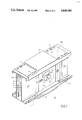
- FIG. 1 is a front perspective view of an adjustable electrical busway joint according to the invention
- FIG. 2 is a top perspective view in partial section of the adjustable busway joint of FIG. 1 prior to connection with a pair of adjacent busway sections;
- FIG. 3 is a plan view in partial section of the busway joint of FIG. 1 with the cover removed;
- FIG. 4 is a front perspective view of an alternate embodiment of the adjustable bus joint according to the invention.
- FIG. 4A is an alternate embodiment of a splice plate used within the bus joint of FIG. 4.
- the busway joint 10, according to the invention is depicted in FIG. 1 attached to adjoining electrical busway sections 11 and 12. Electrically conducting bus bars 15-18 are depicted within busway section 11 between opposing side plates 14A, 14B. Similar bus bars are contained within busway section 12 and are arranged between similar opposing side plates 13A, 13B.
- the busway joint is fastened between the adjoining busway section by means of a thru-bolt 29 which extends through a rectangular washer 26 and a Belville washer 25.
- the rectangular washer is kept from rotating by means of slots 27 formed in the rectangular washer and tabs 28, extending from the face plate of the busway joint.
- the busway joint is enclosed at the bottom by means of a bottom cover 19 and at the top by means of a top cover 20.
- the top cover 20 includes slots 22 through which upstanding tabs 21 formed on the busway section side plates 13A, 13B and 14A, 14B extend. Slots 24 are similarly formed within the top cover 20 to receive corresponding bolts 23 which extend down through the slots and threadingly connect with the busway sections in a similar manner. As described in aforementioned U.S. Pat. No. 3,489,846, the slots provide expansion accommodation for thermal purposes.
- busway joint and busway sections are interconnected in the manner best seen by referring now to FIG. 2 wherein a bus joint connector module 30 such as described within the aforementioned U.S. Pat. Application Ser. No. 193,000 is indicated.
- alternating metallic splice plates 30A are interleaved between non-metallic insulating plates 30B for connecting with the adjoining bus bars.
- the oval tube 35 extending through the connector module exists through the joint side frames 33, 34 by means of oval-shaped slots 36.
- bus bars 15A-18A are arranged for interconnection with corresponding bus bars 15B-18B arranged between the side plates 13A, 13B in the adjacent busway section 12, as also indicated in phantom.
- a vertically extending rail 31 is integrally formed at the end of each of the side plates 14A, 14B which are received within channels 32 integrally formed within the busway joint side frames 33, 34.
- the width of the channel recess 32A is larger than the width of the vertically extending rail 31 to allow for relative motion therebetween.
- busway joint side frames 33, 34 are fastened to each other and to the connector module 30 by means of a thru-bolt 42, rectangular washer 41, Belville washer 39, by means of circular slot 40 and by means of a tabbed washer 37 which contains an oval slot 38.
- the busway joint side plates provide excellent electrical connection with the side plates of the respective busway sections to insure good ground continuity through the joint side plates. This is essential when the side plates of the busway system provide the necessary ground conduction as described, for example, in the aforementioned U.S. Pat. Application Ser. No. 122,863. Ground continuity through the bus joint is also provided by means of the top and bottom covers 20, 19 of FIG.
- the tabbed washer 37 is fitted over the protruding end of the oval tube 35 and the tabs 37A-37D are inserted within corresponding slots 41A-41D in the rectangular washer 41 to prevent the rectangular washer from rotating during attachment between the bus way joint and the busway sections.
- Similar tabbed washers 37, Belville washers 39 and rectangular washers 43 are provided on the opposite side of the busway joint except that the rectangular washer 43 is threaded to engage the thru-bolt 42.
- the location of the rails 31 relative to the channels 32 is determined by viewing the vertically extending rail surface 31A through the viewing slot 44 formed within the channel 32.
- the tool access slots 45 that are formed along the edges of the viewing slot facilitate the entry of a levering tool, such as a screwdriver, for moving the rails 31 within the channels 32.
- the location of the rails 31 within the channels 32 within the busway joint 10 in FIG. 1 is readily indicated by means of the surface 31A which is coated with indicia to highlight the rails when seen from the exterior of the viewing slot 44.
- the assembled busway joint of FIG. 1 is depicted in FIG. 3 with the cover removed to show the location of the busway rails 31 within the bus joint channels 32 and to indicate the clearance provided within the bus joint channels by means of the width of the recesses 32A. Also indicated is the connection between the bus bars 15A-18A within the busway section 12 with the bus bars 15B-18B within busway section 13 through the connector module 30.
- FIG. 4 An alternate busway joint 46 is depicted in FIG. 4 with the connector module omitted and the bus bars within the adjoining busway sections 47, 48 all omitted for purposes of clarity.
- a pair of tabs 51 are lanced within the side plates 49A, 49B and a similar pair of tabs 52 are lanced within the side plates 50A, 50B of the busway section 48.
- Complementary slots 54, 55 are formed on opposite ends of the busway joint 46 to receive the respective tabs when the busway sections are inserted within the ends of the busway joint.
- FIG. 4A An alternate splice plate 61 is depicted in FIG. 4A which consists of a metal plate 63 with an insulative epoxy coating 64 applied to both sides thereof by a selective coating process which leaves a contact area 63A devoid of such coating.
- This splice plate accordingly does not require alternating insulating plates such as depicted at 30B in FIG. 2.
- a good description of the combined insulating-splice plate is found within the aforementioned U.S. Pat. Application Ser. No. 193,000.
Abstract
Description
Claims (30)
Priority Applications (5)
| Application Number | Priority Date | Filing Date | Title |
|---|---|---|---|
| US07/194,655 US4849581A (en) | 1988-05-16 | 1988-05-16 | Adjustable joint for electrical busway |
| CA000594601A CA1316997C (en) | 1988-05-16 | 1989-03-23 | Adjustable joint for electrical busway |
| AU33122/89A AU3312289A (en) | 1988-05-16 | 1989-04-18 | Adjustable joint for electrical busway |
| JP1118871A JPH0236717A (en) | 1988-05-16 | 1989-05-15 | Adjustable bus-bar joint |
| KR1019890006494A KR890017833A (en) | 1988-05-16 | 1989-05-16 | Adjustable joint for electric busway |
Applications Claiming Priority (1)
| Application Number | Priority Date | Filing Date | Title |
|---|---|---|---|
| US07/194,655 US4849581A (en) | 1988-05-16 | 1988-05-16 | Adjustable joint for electrical busway |
Publications (1)
| Publication Number | Publication Date |
|---|---|
| US4849581A true US4849581A (en) | 1989-07-18 |
Family
ID=22718407
Family Applications (1)
| Application Number | Title | Priority Date | Filing Date |
|---|---|---|---|
| US07/194,655 Expired - Fee Related US4849581A (en) | 1988-05-16 | 1988-05-16 | Adjustable joint for electrical busway |
Country Status (5)
| Country | Link |
|---|---|
| US (1) | US4849581A (en) |
| JP (1) | JPH0236717A (en) |
| KR (1) | KR890017833A (en) |
| AU (1) | AU3312289A (en) |
| CA (1) | CA1316997C (en) |
Cited By (47)
| Publication number | Priority date | Publication date | Assignee | Title |
|---|---|---|---|---|
| US4950841A (en) * | 1989-05-30 | 1990-08-21 | General Electric Company | Thermally efficient splice joint for electrical distribution busway |
| US5068763A (en) * | 1990-10-29 | 1991-11-26 | General Electric Company | Electric busway-meter module arrangement |
| US5141448A (en) * | 1991-12-02 | 1992-08-25 | Matrix Science Corporation | Apparatus for retaining a coupling ring in non-self locking electrical connectors |
| US5442135A (en) * | 1993-03-25 | 1995-08-15 | Siemens Energy & Automation, Inc. | Electrical power distribution busway and housing |
| US5466889A (en) * | 1993-03-25 | 1995-11-14 | Siemens Energy & Automation, Inc. | Electrical power busway and insulator assembly |
| US5486651A (en) * | 1993-03-25 | 1996-01-23 | Siemens Energy & Automation, Inc. | Multi-neural electrical busway |
| WO1996029768A1 (en) * | 1995-03-17 | 1996-09-26 | Klockner-Moeller Gmbh | Busbar joint with means for attaching a cover |
| US5619014A (en) * | 1993-03-25 | 1997-04-08 | Siemens Energy & Automation, Inc. | Busway busbar with plug-in tab |
| US5760339A (en) * | 1993-03-25 | 1998-06-02 | Siemens Energy & Automation, Inc. | Busway joint |
| EP0877460A2 (en) * | 1997-04-29 | 1998-11-11 | Ciama C, S.L. | Improvements in grouped busbars for the transportation and distribution of electricity |
| US5941654A (en) * | 1995-11-13 | 1999-08-24 | Erico International Corporation | Bus bar assembly, fastening system therefor, and method |
| US6329598B1 (en) | 1999-08-27 | 2001-12-11 | General Electric Company | Water-resistant busway with water drainage duct |
| WO2003069747A2 (en) * | 2002-02-13 | 2003-08-21 | Bbi Electric S.P.A. | Splice joint for busbars |
| US6870103B1 (en) * | 2003-09-05 | 2005-03-22 | Siemens Energy & Automation, Inc. | Bus joint cover assembly |
| US20050077072A1 (en) * | 2003-10-14 | 2005-04-14 | Siemens Energy & Automation, Inc. | Channel bus splice assembly |
| US20100012375A1 (en) * | 2008-07-18 | 2010-01-21 | Jur Arthur J | Electrical busway and offset coupling assembly therefor |
| KR100971334B1 (en) | 2008-01-23 | 2010-07-20 | 엘에스전선 주식회사 | Bus bars joint improved accuracy of assemble and absorption of thermal expansion |
| US7819681B1 (en) * | 2009-06-19 | 2010-10-26 | Rodrigues Carlton R | Thermally efficient busway joint pack |
| US20110132635A1 (en) * | 2009-12-03 | 2011-06-09 | Square D Company | Nesting dielectric insulators |
| US20110304211A1 (en) * | 2010-06-09 | 2011-12-15 | Microsoft Corporation | Rack-Based Uninterruptible Power Supply |
| CN102820567A (en) * | 2012-08-22 | 2012-12-12 | 广州市半径电力铜材有限公司 | Intensive connector |
| US8487473B2 (en) | 2010-06-24 | 2013-07-16 | Microsoft Corporation | Hierarchical power smoothing |
| US8540526B2 (en) | 2011-12-28 | 2013-09-24 | General Electric Company | Adjustable electrical busway joint |
| US8550830B1 (en) * | 2012-06-01 | 2013-10-08 | General Electric Company | Connector for interconnecting three busway at its three ends |
| US20130327570A1 (en) * | 2012-06-06 | 2013-12-12 | Kuldeep Kumar Bhathija | Methods and systems for coupling different size busway sections |
| US8662940B2 (en) | 2011-12-28 | 2014-03-04 | General Electric Company | Electrical connectors and methods for coupling the electrical connectors to busbars |
| US8690612B2 (en) | 2011-12-28 | 2014-04-08 | General Electric Company | Electrical connectors and methods for coupling the electrical connectors to busbars |
| US8782443B2 (en) | 2010-05-25 | 2014-07-15 | Microsoft Corporation | Resource-based adaptive server loading |
| US8847088B2 (en) | 2011-09-22 | 2014-09-30 | General Electric Company | Cover mounted handle operating mechanism with integrated interlock assembly for a busplug enclosure |
| US8864510B2 (en) | 2012-10-31 | 2014-10-21 | Schneider Electric USA, Inc. | Bolt free electrical bus connector |
| US8900002B2 (en) | 2011-12-28 | 2014-12-02 | General Electric Company | Adjustable electrical busway joint |
| US8926351B2 (en) * | 2012-11-20 | 2015-01-06 | Schneider Electric USA, Inc. | Busway joint pack with heat sink insert |
| US20150008007A1 (en) * | 2013-07-08 | 2015-01-08 | Eaton Corporation | Busway Joint Structural Support Assemblies and Related Systems |
| US8932088B2 (en) | 2012-04-23 | 2015-01-13 | Thomas & Betts International, Inc. | Anti-turn mechanism for multiple connector sizes |
| US8952566B2 (en) | 2010-10-26 | 2015-02-10 | Microsoft Technology Licensing, Llc | Chassis slots accepting battery modules and other module types |
| US9071028B2 (en) * | 2010-11-02 | 2015-06-30 | Sma Solar Technology Ag | Electrical connection between two busbars made of flat conductors and of an insulating layer disposed between the conductors |
| US9520688B2 (en) | 2014-10-13 | 2016-12-13 | Electrical Intellectual Property Limited | Joint assembly for a busduct |
| US9590406B1 (en) | 2016-01-07 | 2017-03-07 | General Electric Company | Busway joint coupling having a splice plate with a longitudinal rib |
| US9590405B1 (en) | 2016-01-07 | 2017-03-07 | General Electric Company | Busway joint coupling having an adjustable assembly for joining two busway sections |
| US9705299B1 (en) | 2016-01-07 | 2017-07-11 | General Electric Company | Electrical busway joint with external vise braces |
| US9705300B1 (en) | 2016-01-07 | 2017-07-11 | General Electric Company | Electrical busway joint with laminated bracing system |
| US20170201080A1 (en) * | 2016-01-07 | 2017-07-13 | General Electric Company | Electrical busway joint with self-adjusting braces |
| US10411453B1 (en) * | 2018-04-25 | 2019-09-10 | Siemens Industry, Inc. | Electrical bus assemblies, yoke brace apparatus, bus bar support assemblies, and methods |
| US10686300B2 (en) | 2016-07-13 | 2020-06-16 | Zodiac Aero Electric | Device for electrically connecting power distribution plates and electrical power distribution system provided with such a connection device |
| US11133629B2 (en) * | 2015-04-16 | 2021-09-28 | Eaton Intelligent Power Limited | Busway systems and related assemblies and methods |
| US20220278517A1 (en) * | 2021-03-01 | 2022-09-01 | Yazaki Corporation | Fastening structure, aluminum wiring material, and method of manufacturing fastening structure |
| US11788625B2 (en) | 2020-05-27 | 2023-10-17 | Hoffman Enclosures, Inc. | Hygienic hole seal |
Families Citing this family (2)
| Publication number | Priority date | Publication date | Assignee | Title |
|---|---|---|---|---|
| JP7131592B2 (en) * | 2019-11-14 | 2022-09-06 | Jfeスチール株式会社 | Structural member for automobile and method for reinforcing hollow member for automobile |
| RU204792U1 (en) * | 2021-03-31 | 2021-06-11 | Общество с ограниченной ответственностью "ПСК ПЛАСТМЕТАЛЛ" (ООО "ПСК Пластметалл") | Solid insulated conductor joint |
Citations (8)
| Publication number | Priority date | Publication date | Assignee | Title |
|---|---|---|---|---|
| US3009011A (en) * | 1956-03-02 | 1961-11-14 | Gen Electric | Distribution system |
| US3365537A (en) * | 1966-08-05 | 1968-01-23 | Gen Electric | Waterproof thru-bolt joint for joining adjacent sections of an electric power busway |
| US3489846A (en) * | 1967-09-29 | 1970-01-13 | Gen Electric | Busway joint cover with expansion accommodating means |
| US3559148A (en) * | 1969-06-11 | 1971-01-26 | Arrow Hart Inc | Busbar coupler system |
| US3609215A (en) * | 1969-05-07 | 1971-09-28 | Gen Electric | Electric power busway with thermal expansion absorbing joints |
| US3786394A (en) * | 1972-03-22 | 1974-01-15 | Cutler Hammer Inc | Single-bolt joint for feeder and plug-in bus ducts |
| US3922053A (en) * | 1972-04-18 | 1975-11-25 | Arrow Hart Inc | Plug-in bus duct |
| US4705334A (en) * | 1984-09-13 | 1987-11-10 | Square D Company | Electrical distribution system having an improved splice joint between busway sections |
-
1988
- 1988-05-16 US US07/194,655 patent/US4849581A/en not_active Expired - Fee Related
-
1989
- 1989-03-23 CA CA000594601A patent/CA1316997C/en not_active Expired - Lifetime
- 1989-04-18 AU AU33122/89A patent/AU3312289A/en not_active Abandoned
- 1989-05-15 JP JP1118871A patent/JPH0236717A/en active Pending
- 1989-05-16 KR KR1019890006494A patent/KR890017833A/en not_active Application Discontinuation
Patent Citations (8)
| Publication number | Priority date | Publication date | Assignee | Title |
|---|---|---|---|---|
| US3009011A (en) * | 1956-03-02 | 1961-11-14 | Gen Electric | Distribution system |
| US3365537A (en) * | 1966-08-05 | 1968-01-23 | Gen Electric | Waterproof thru-bolt joint for joining adjacent sections of an electric power busway |
| US3489846A (en) * | 1967-09-29 | 1970-01-13 | Gen Electric | Busway joint cover with expansion accommodating means |
| US3609215A (en) * | 1969-05-07 | 1971-09-28 | Gen Electric | Electric power busway with thermal expansion absorbing joints |
| US3559148A (en) * | 1969-06-11 | 1971-01-26 | Arrow Hart Inc | Busbar coupler system |
| US3786394A (en) * | 1972-03-22 | 1974-01-15 | Cutler Hammer Inc | Single-bolt joint for feeder and plug-in bus ducts |
| US3922053A (en) * | 1972-04-18 | 1975-11-25 | Arrow Hart Inc | Plug-in bus duct |
| US4705334A (en) * | 1984-09-13 | 1987-11-10 | Square D Company | Electrical distribution system having an improved splice joint between busway sections |
Cited By (60)
| Publication number | Priority date | Publication date | Assignee | Title |
|---|---|---|---|---|
| US4950841A (en) * | 1989-05-30 | 1990-08-21 | General Electric Company | Thermally efficient splice joint for electrical distribution busway |
| US5068763A (en) * | 1990-10-29 | 1991-11-26 | General Electric Company | Electric busway-meter module arrangement |
| US5141448A (en) * | 1991-12-02 | 1992-08-25 | Matrix Science Corporation | Apparatus for retaining a coupling ring in non-self locking electrical connectors |
| US5760339A (en) * | 1993-03-25 | 1998-06-02 | Siemens Energy & Automation, Inc. | Busway joint |
| US5442135A (en) * | 1993-03-25 | 1995-08-15 | Siemens Energy & Automation, Inc. | Electrical power distribution busway and housing |
| US5466889A (en) * | 1993-03-25 | 1995-11-14 | Siemens Energy & Automation, Inc. | Electrical power busway and insulator assembly |
| US5486651A (en) * | 1993-03-25 | 1996-01-23 | Siemens Energy & Automation, Inc. | Multi-neural electrical busway |
| US5619014A (en) * | 1993-03-25 | 1997-04-08 | Siemens Energy & Automation, Inc. | Busway busbar with plug-in tab |
| WO1996029768A1 (en) * | 1995-03-17 | 1996-09-26 | Klockner-Moeller Gmbh | Busbar joint with means for attaching a cover |
| GB2300762B (en) * | 1995-03-17 | 1999-06-16 | Barduct Ltd | Improvements in or relating to busbars |
| US5941654A (en) * | 1995-11-13 | 1999-08-24 | Erico International Corporation | Bus bar assembly, fastening system therefor, and method |
| EP0877460A2 (en) * | 1997-04-29 | 1998-11-11 | Ciama C, S.L. | Improvements in grouped busbars for the transportation and distribution of electricity |
| EP0877460A3 (en) * | 1997-04-29 | 1999-03-31 | Ciama C, S.L. | Improvements in grouped busbars for the transportation and distribution of electricity |
| ES2129359A1 (en) * | 1997-04-29 | 1999-06-01 | Ciama Busbar S L | Bar groupings device to tranport and distribute electricity |
| US6329598B1 (en) | 1999-08-27 | 2001-12-11 | General Electric Company | Water-resistant busway with water drainage duct |
| WO2003069747A2 (en) * | 2002-02-13 | 2003-08-21 | Bbi Electric S.P.A. | Splice joint for busbars |
| WO2003069747A3 (en) * | 2002-02-13 | 2003-12-04 | Bbi Electric Spa | Splice joint for busbars |
| CN100407530C (en) * | 2002-02-13 | 2008-07-30 | Bbi电气有限公司 | Bus bar joint |
| US6870103B1 (en) * | 2003-09-05 | 2005-03-22 | Siemens Energy & Automation, Inc. | Bus joint cover assembly |
| US20050061534A1 (en) * | 2003-09-05 | 2005-03-24 | Siemens Energy & Automation, Inc. | Bus joint cover assembly |
| US20050077072A1 (en) * | 2003-10-14 | 2005-04-14 | Siemens Energy & Automation, Inc. | Channel bus splice assembly |
| KR100971334B1 (en) | 2008-01-23 | 2010-07-20 | 엘에스전선 주식회사 | Bus bars joint improved accuracy of assemble and absorption of thermal expansion |
| US20100012375A1 (en) * | 2008-07-18 | 2010-01-21 | Jur Arthur J | Electrical busway and offset coupling assembly therefor |
| US7819681B1 (en) * | 2009-06-19 | 2010-10-26 | Rodrigues Carlton R | Thermally efficient busway joint pack |
| US20110132635A1 (en) * | 2009-12-03 | 2011-06-09 | Square D Company | Nesting dielectric insulators |
| US8378219B2 (en) * | 2009-12-03 | 2013-02-19 | Schneider Electric USA, Inc. | Nesting dielectric insulators |
| US8782443B2 (en) | 2010-05-25 | 2014-07-15 | Microsoft Corporation | Resource-based adaptive server loading |
| US20110304211A1 (en) * | 2010-06-09 | 2011-12-15 | Microsoft Corporation | Rack-Based Uninterruptible Power Supply |
| US8384244B2 (en) * | 2010-06-09 | 2013-02-26 | Microsoft Corporation | Rack-based uninterruptible power supply |
| US8487473B2 (en) | 2010-06-24 | 2013-07-16 | Microsoft Corporation | Hierarchical power smoothing |
| US8952566B2 (en) | 2010-10-26 | 2015-02-10 | Microsoft Technology Licensing, Llc | Chassis slots accepting battery modules and other module types |
| US9071028B2 (en) * | 2010-11-02 | 2015-06-30 | Sma Solar Technology Ag | Electrical connection between two busbars made of flat conductors and of an insulating layer disposed between the conductors |
| US8847088B2 (en) | 2011-09-22 | 2014-09-30 | General Electric Company | Cover mounted handle operating mechanism with integrated interlock assembly for a busplug enclosure |
| US8662940B2 (en) | 2011-12-28 | 2014-03-04 | General Electric Company | Electrical connectors and methods for coupling the electrical connectors to busbars |
| US8690612B2 (en) | 2011-12-28 | 2014-04-08 | General Electric Company | Electrical connectors and methods for coupling the electrical connectors to busbars |
| US8900002B2 (en) | 2011-12-28 | 2014-12-02 | General Electric Company | Adjustable electrical busway joint |
| US8540526B2 (en) | 2011-12-28 | 2013-09-24 | General Electric Company | Adjustable electrical busway joint |
| US8932088B2 (en) | 2012-04-23 | 2015-01-13 | Thomas & Betts International, Inc. | Anti-turn mechanism for multiple connector sizes |
| CN103457123A (en) * | 2012-06-01 | 2013-12-18 | 通用电气公司 | Connector for interconnecting three busway at its three ends |
| US8550830B1 (en) * | 2012-06-01 | 2013-10-08 | General Electric Company | Connector for interconnecting three busway at its three ends |
| US20130327570A1 (en) * | 2012-06-06 | 2013-12-12 | Kuldeep Kumar Bhathija | Methods and systems for coupling different size busway sections |
| CN102820567A (en) * | 2012-08-22 | 2012-12-12 | 广州市半径电力铜材有限公司 | Intensive connector |
| CN102820567B (en) * | 2012-08-22 | 2014-12-31 | 广州市半径电力铜材有限公司 | Intensive connector |
| US8864510B2 (en) | 2012-10-31 | 2014-10-21 | Schneider Electric USA, Inc. | Bolt free electrical bus connector |
| US8926351B2 (en) * | 2012-11-20 | 2015-01-06 | Schneider Electric USA, Inc. | Busway joint pack with heat sink insert |
| US9197045B2 (en) * | 2013-07-08 | 2015-11-24 | Eaton Corporation | Busway joint structural support assemblies and related systems |
| US20150008007A1 (en) * | 2013-07-08 | 2015-01-08 | Eaton Corporation | Busway Joint Structural Support Assemblies and Related Systems |
| US9520688B2 (en) | 2014-10-13 | 2016-12-13 | Electrical Intellectual Property Limited | Joint assembly for a busduct |
| US11133629B2 (en) * | 2015-04-16 | 2021-09-28 | Eaton Intelligent Power Limited | Busway systems and related assemblies and methods |
| US20170201080A1 (en) * | 2016-01-07 | 2017-07-13 | General Electric Company | Electrical busway joint with self-adjusting braces |
| US9705299B1 (en) | 2016-01-07 | 2017-07-11 | General Electric Company | Electrical busway joint with external vise braces |
| US9705300B1 (en) | 2016-01-07 | 2017-07-11 | General Electric Company | Electrical busway joint with laminated bracing system |
| US9590405B1 (en) | 2016-01-07 | 2017-03-07 | General Electric Company | Busway joint coupling having an adjustable assembly for joining two busway sections |
| US9882366B2 (en) * | 2016-01-07 | 2018-01-30 | General Electric Company | Electrical busway joint with self-adjusting braces |
| US9590406B1 (en) | 2016-01-07 | 2017-03-07 | General Electric Company | Busway joint coupling having a splice plate with a longitudinal rib |
| US10686300B2 (en) | 2016-07-13 | 2020-06-16 | Zodiac Aero Electric | Device for electrically connecting power distribution plates and electrical power distribution system provided with such a connection device |
| US10693281B2 (en) * | 2016-07-13 | 2020-06-23 | Zodiac Aero Electric | Device for electrically connecting power distribution plates and electrical power distribution system provided with such a connection device |
| US10411453B1 (en) * | 2018-04-25 | 2019-09-10 | Siemens Industry, Inc. | Electrical bus assemblies, yoke brace apparatus, bus bar support assemblies, and methods |
| US11788625B2 (en) | 2020-05-27 | 2023-10-17 | Hoffman Enclosures, Inc. | Hygienic hole seal |
| US20220278517A1 (en) * | 2021-03-01 | 2022-09-01 | Yazaki Corporation | Fastening structure, aluminum wiring material, and method of manufacturing fastening structure |
Also Published As
| Publication number | Publication date |
|---|---|
| CA1316997C (en) | 1993-04-27 |
| AU3312289A (en) | 1989-11-16 |
| JPH0236717A (en) | 1990-02-06 |
| KR890017833A (en) | 1989-12-18 |
Similar Documents
| Publication | Publication Date | Title |
|---|---|---|
| US4849581A (en) | Adjustable joint for electrical busway | |
| US4804804A (en) | Thermally efficient power busway housing | |
| US4950841A (en) | Thermally efficient splice joint for electrical distribution busway | |
| US6039584A (en) | Electrical power distribution system | |
| US6329598B1 (en) | Water-resistant busway with water drainage duct | |
| US3922053A (en) | Plug-in bus duct | |
| US5847321A (en) | Busbar device for an electrical distribution cabinet | |
| KR930010603B1 (en) | Electrical distribution system with an improved housing | |
| US4820178A (en) | Outlet box for electric busway system | |
| US8163998B2 (en) | Electrical busway flange end stub | |
| KR930010604B1 (en) | Electrical distribution system having an improved plug in assembly for current tap-off | |
| US4041358A (en) | Meter module assembly for a meter panel | |
| KR20090059057A (en) | System and method for securing a busway housing to busway power conductors | |
| CA2064510C (en) | Power distribution apparatus | |
| US5068763A (en) | Electric busway-meter module arrangement | |
| JPS63155514A (en) | Equipment adaptor for electric and mechanic connection of wiring apparatus | |
| US4199655A (en) | Circuit breaker with insulated horizontal bus bars | |
| US3732523A (en) | Bus duct system including improved plug-in power take-off means | |
| RU2036543C1 (en) | Multicubicle switchgear installation with collecting buses passed through cubicles and bus wiring device | |
| US4723917A (en) | Device for low voltage electric distribution | |
| US4360857A (en) | Modular insulative support base for electrical switchgear | |
| US6201722B1 (en) | Inter-bay bipolar DC bus link | |
| US3710300A (en) | Clamping adjustment feature for bus duct housing | |
| JPH10164736A (en) | Bus-bar supporting device | |
| EP1215789A1 (en) | Busbar device for electrical power |
Legal Events
| Date | Code | Title | Description |
|---|---|---|---|
| AS | Assignment |
Owner name: GENERAL ELECTRIC COMPANY, A CORP. OF NY Free format text: ASSIGNMENT OF ASSIGNORS INTEREST.;ASSIGNORS:LARKIN, HAROLD F.;HIBBERT, DAVID A.;BEBERMAN, JULIE A.;REEL/FRAME:004891/0745 Effective date: 19880512 Owner name: GENERAL ELECTRIC COMPANY, A CORP. OF NY, NEW YORK Free format text: ASSIGNMENT OF ASSIGNORS INTEREST;ASSIGNORS:LARKIN, HAROLD F.;HIBBERT, DAVID A.;BEBERMAN, JULIE A.;REEL/FRAME:004891/0745 Effective date: 19880512 |
|
| AS | Assignment |
Owner name: GENERAL ELECTRIC COMPANY, A CORP. OF NY, STATELESS Free format text: ASSIGNMENT OF ASSIGNORS INTEREST.;ASSIGNOR:WALKER, CLARENCE W.;REEL/FRAME:005098/0577 Effective date: 19880627 |
|
| FEPP | Fee payment procedure |
Free format text: PAYOR NUMBER ASSIGNED (ORIGINAL EVENT CODE: ASPN); ENTITY STATUS OF PATENT OWNER: LARGE ENTITY |
|
| REMI | Maintenance fee reminder mailed | ||
| LAPS | Lapse for failure to pay maintenance fees | ||
| FP | Lapsed due to failure to pay maintenance fee |
Effective date: 19930718 |
|
| STCH | Information on status: patent discontinuation |
Free format text: PATENT EXPIRED DUE TO NONPAYMENT OF MAINTENANCE FEES UNDER 37 CFR 1.362 |