US4848870A - Optical fiber jaw connector - Google Patents
Optical fiber jaw connector Download PDFInfo
- Publication number
- US4848870A US4848870A US07/178,115 US17811588A US4848870A US 4848870 A US4848870 A US 4848870A US 17811588 A US17811588 A US 17811588A US 4848870 A US4848870 A US 4848870A
- Authority
- US
- United States
- Prior art keywords
- jaws
- optical fiber
- aligning
- contact
- jaw
- Prior art date
- Legal status (The legal status is an assumption and is not a legal conclusion. Google has not performed a legal analysis and makes no representation as to the accuracy of the status listed.)
- Expired - Fee Related
Links
Images


Classifications
-
- G—PHYSICS
- G02—OPTICS
- G02B—OPTICAL ELEMENTS, SYSTEMS OR APPARATUS
- G02B6/00—Light guides; Structural details of arrangements comprising light guides and other optical elements, e.g. couplings
- G02B6/24—Coupling light guides
- G02B6/36—Mechanical coupling means
- G02B6/38—Mechanical coupling means having fibre to fibre mating means
- G02B6/3807—Dismountable connectors, i.e. comprising plugs
- G02B6/3809—Dismountable connectors, i.e. comprising plugs without a ferrule embedding the fibre end, i.e. with bare fibre end
-
- G—PHYSICS
- G02—OPTICS
- G02B—OPTICAL ELEMENTS, SYSTEMS OR APPARATUS
- G02B6/00—Light guides; Structural details of arrangements comprising light guides and other optical elements, e.g. couplings
- G02B6/24—Coupling light guides
- G02B6/36—Mechanical coupling means
- G02B6/38—Mechanical coupling means having fibre to fibre mating means
- G02B6/3807—Dismountable connectors, i.e. comprising plugs
- G02B6/381—Dismountable connectors, i.e. comprising plugs of the ferrule type, e.g. fibre ends embedded in ferrules, connecting a pair of fibres
- G02B6/3825—Dismountable connectors, i.e. comprising plugs of the ferrule type, e.g. fibre ends embedded in ferrules, connecting a pair of fibres with an intermediate part, e.g. adapter, receptacle, linking two plugs
-
- G—PHYSICS
- G02—OPTICS
- G02B—OPTICAL ELEMENTS, SYSTEMS OR APPARATUS
- G02B6/00—Light guides; Structural details of arrangements comprising light guides and other optical elements, e.g. couplings
- G02B6/24—Coupling light guides
- G02B6/36—Mechanical coupling means
- G02B6/38—Mechanical coupling means having fibre to fibre mating means
- G02B6/3807—Dismountable connectors, i.e. comprising plugs
- G02B6/3833—Details of mounting fibres in ferrules; Assembly methods; Manufacture
- G02B6/3834—Means for centering or aligning the light guide within the ferrule
- G02B6/3841—Means for centering or aligning the light guide within the ferrule using rods, balls for light guides
-
- G—PHYSICS
- G02—OPTICS
- G02B—OPTICAL ELEMENTS, SYSTEMS OR APPARATUS
- G02B6/00—Light guides; Structural details of arrangements comprising light guides and other optical elements, e.g. couplings
- G02B6/24—Coupling light guides
- G02B6/36—Mechanical coupling means
- G02B6/38—Mechanical coupling means having fibre to fibre mating means
- G02B6/3807—Dismountable connectors, i.e. comprising plugs
- G02B6/3833—Details of mounting fibres in ferrules; Assembly methods; Manufacture
- G02B6/3847—Details of mounting fibres in ferrules; Assembly methods; Manufacture with means preventing fibre end damage, e.g. recessed fibre surfaces
-
- G—PHYSICS
- G02—OPTICS
- G02B—OPTICAL ELEMENTS, SYSTEMS OR APPARATUS
- G02B6/00—Light guides; Structural details of arrangements comprising light guides and other optical elements, e.g. couplings
- G02B6/24—Coupling light guides
- G02B6/36—Mechanical coupling means
- G02B6/38—Mechanical coupling means having fibre to fibre mating means
- G02B6/3807—Dismountable connectors, i.e. comprising plugs
- G02B6/3887—Anchoring optical cables to connector housings, e.g. strain relief features
- G02B6/3888—Protection from over-extension or over-compression
-
- G—PHYSICS
- G02—OPTICS
- G02B—OPTICAL ELEMENTS, SYSTEMS OR APPARATUS
- G02B6/00—Light guides; Structural details of arrangements comprising light guides and other optical elements, e.g. couplings
- G02B6/24—Coupling light guides
- G02B6/36—Mechanical coupling means
- G02B6/38—Mechanical coupling means having fibre to fibre mating means
- G02B6/3807—Dismountable connectors, i.e. comprising plugs
- G02B6/389—Dismountable connectors, i.e. comprising plugs characterised by the method of fastening connecting plugs and sockets, e.g. screw- or nut-lock, snap-in, bayonet type
-
- G—PHYSICS
- G02—OPTICS
- G02B—OPTICAL ELEMENTS, SYSTEMS OR APPARATUS
- G02B6/00—Light guides; Structural details of arrangements comprising light guides and other optical elements, e.g. couplings
- G02B6/24—Coupling light guides
- G02B6/36—Mechanical coupling means
- G02B6/38—Mechanical coupling means having fibre to fibre mating means
- G02B6/3807—Dismountable connectors, i.e. comprising plugs
- G02B6/3897—Connectors fixed to housings, casing, frames or circuit boards
-
- G—PHYSICS
- G02—OPTICS
- G02B—OPTICAL ELEMENTS, SYSTEMS OR APPARATUS
- G02B6/00—Light guides; Structural details of arrangements comprising light guides and other optical elements, e.g. couplings
- G02B6/24—Coupling light guides
- G02B6/36—Mechanical coupling means
- G02B6/38—Mechanical coupling means having fibre to fibre mating means
- G02B6/3807—Dismountable connectors, i.e. comprising plugs
- G02B6/3898—Tools, e.g. handheld; Tuning wrenches; Jigs used with connectors, e.g. for extracting, removing or inserting in a panel, for engaging or coupling connectors, for assembling or disassembling components within the connector, for applying clips to hold two connectors together or for crimping
Definitions
- the present invention relates to an optical fiber connector which aligns fibers by aligning the outer surfaces thereof.
- optical fibers have extensively been deployed for information transfer purposes, optical fibers being preferred over electrical conduction means since optical fiber is capable of transmitting larger amounts of information and is immune from electromagnetic interference.
- electrical conduction means since optical fiber is capable of transmitting larger amounts of information and is immune from electromagnetic interference.
- Mouissie U.S. Pat. No. 4,354,731 discloses a connector which includes two floating centering jaws each of which contains an aligning V-groove therein.
- an insertion force of the bare fibers is used to urge the jaws apart.
- one or more side wedges is used to allow for a zero insertion force for the fibers and subsequent to fiber insertion the wedges are withdrawn allowing elastomeric rings to urge the jaws into aligning contact with the fibers.
- ends of the fibers are often scratched, scraped, or broken when inserted into such constructions even when wedges are employed to attempt to eliminate a fiber insertion force.
- the use of the disclosed wedges results in a complex construction which is difficult to make and also difficult to use by a craftsman.
- FIG. 32 discloses a connector whereby an optical fiber 274 contained within a retractable tube 284 of a fiber contact is inserted into a connector aligning aperture defined by opposing V-grooves in elastomeric members 246, 254. The contact is secured to the connector and the elastomeric members are urged into aligning contact with the fiber by applying threadable sleeve 290.
- the embodiment of FIGS. 37-42 is similar in that opposing elastomeric members having opposing V-grooves are compressed using compression nut 328 subsequent to connecting a fiber contact to a fiber contact connector.
- an optical fiber connector which includes:
- a plurality of separable jaws for aligning first and second optical fiber ends, the jaws being mateable so as to form a fiber aligning aperture longitudinally therethrough for aligning first and second optical fiber ends therein;
- first means disengaging the first engaging means from the jaw entrance an amount sufficient for the first biasing means to urge the jaws into aligning contact with the first optical fiber end subsequent to inserting the first optical fiber into the aligning aperture.
- FIGS. 1 and 2 illustrate a preferred jaw construction according to the invention
- FIG. 3 illustrates a preferred embodiment of a connector according to the invention
- FIG. 4 illustrates another preferred embodiment of a connector according to the invention
- FIGS. 5 and 6 illustrate two additional preferred embodiments of connectors according to the invention
- FIG. 7 illustrates a series of connectors on a multiple connect panel according to the invention.
- FIGS. 8 and 9 illustrate a preferred embodiment of a tool for aiding connection of optical fiber contact with a connector according to the invention.
- FIGS. 1 and 2 illustrate a preferred jaw construction for an optical fiber connector according to the invention.
- the jaw construction comprises preferably three jaws 2 biased radially inwardly by a pair of elastomeric ring springs 4.
- Each jaw 2 preferably forms a 120° arc segment of the jaw assembly, as illustrated, and an inner surface of each jaw 2 has a substantially flat surface 8 formed thereon which together form a substantially triangular first fiber aligning aperture 5.
- First and second fibers 17, 18, which generally comprise a cylindrical core and cladding, preferably glass, have their outside cladding diameters aligned by the jaw flat surfaces 8 due to the inwardly biasing force of the rings 4. Since the surfaces 8 are flat, minimal rotational torque forces are induced to the optical fibers 17, 18 during vibration loads and temperature cycling since minimal sideward skew forces are exerted on the optical fibers. Accordingly a stable and reliable connection is achieved thereby.
- Reference numeral 22 illustrates a circular groove formed in an outer circumferential surface of the jaws 2 for accommodating and keeping the biasing rings in place.
- the jaw construction is the provision of substantially flat surfaces 12 extending longitudinally from opposite ends of the fiber aligning aperture 5, the surfaces 12 diverging in a radial direction so as to form an inwardly contracting polygonal-shaped jaw entrance 13 for the fibers while extending them into the fiber aligning aperture 5.
- Means 10 complementary in shape to the jaw entrance 13 is capable of engaging the entrance 13 and expanding the jaws radially outward against the inwardly biasing force of the rings 4 when the means 10 is urged in a direction of the arrow 20 illustrated in FIG. 1.
- the polygon shaped complementary means 10 and entrance 13 allow a simple and efficient way of keying the jaws so as to prevent rotation thereof during vibration loads and temperature cycling so as to prevent skewing of the fibers and hence achieve a stable and predictable connection loss.
- the complementary means 10 includes an aperture 6 through which an optical fiber 17 or 18 can extend so as to allow insertion of the optical fiber into the fiber aligning aperture 5 while the complementary means 10 engages surfaces 12 so as to keep the jaws in an expanded configuration.
- the complementary means 10 remains loosely engaged with the entrance 13 subsequent to fiber connection so as to keep the jaws keyed to prevent skewing of the fibers during vibration loads.
- This construction also allows the jaws to float within the connector, a further feature which results in stable, predictable connection losses.
- Three jaw segments are preferred since optimum radial forces are thus generated against the fibers being aligned, but additional, e.g. 4 or 5, jaws could alternatively be used though skewing of the fibers could thereby result.
- Reference numerals 15 and 16 refer to first and second fiber guiding tubes within which the optical fibers 17, 18 are contained, the tubes extending into the connector just short of the fiber aligning aperture 5.
- the protective tubes allow bare glass fibers to be safely inserted into the connector, as more fully described below.
- FIG. 3 illustrates a preferred embodiment of a connector 90 of the invention.
- a front portion of an optical fiber 18 is completely contained within protective tube 16 which is part of optical fiber contact 81.
- a compression nut 78 at a rear of the contact 81 is utilized to grip a jacket of the optical fiber, and preferably a strain relief member(s) thereof.
- a spring 73 is utilized to normally urge the protective tube 16 in a forward direction, e.g. towards the connector 90.
- a boss 86 of the tube 16 is engageable with a shoulder 87 in an interior of the contact which limits forward movement of the tube 16.
- An end 91 of the optical fiber 18 is recessed a predetermined amount from an end 93 of the tube 16 by a tool (not shown) prior to tightening the compression nut and thereby fixing the relative positions of the ends 91, 93 when the tube 16 is in its fully extended forward state, as illustrated. Therefore, during fiber insertion, the fiber is fully protected by the tube up to the point when the tube end 93 engages stopping surface or shoulder 60 of pyramid collet 82 within the connector 90.
- the connector 90 includes a contact locking member 74 and a connector body 82.
- the locking member 74 has at least two grooves 96 on an outer surface thereof which allow at least two contact extensions to slide longitudinally thereover such that a front end 94 of the contact can engage a shoulder 84 of the connector 90, a front portion 95 of the connector having longitudinal grooves (not shown) on an outer circumference thereof for accommodating the extensions 76.
- Circumferential grooves 97 are formed in the contact extentions 76 which allow the locking member 74 to be rotated subsequent to full contact insertion for locking the contact 81 to the connector 90.
- the connector body includes a pyramid collet 88 on a front thereof which engages jaw entrance surfaces 12 and accordingly opens and closes the jaws, as previously explained.
- a spring 72 urges the body 82 in a direction away from the jaw entrance surfaces 12, and movement of the body 82 is limited by shoulder 89 of the locking member 74.
- the front end 93 of the tube 16 engages the shoulder 60 within the collet 82 prior to a front end 94 of the contact 81 engaging the shoulder 84, a separation between the shoulder 84 and the front end 94 being just slightly larger than a distance that the front end 91 of the fiber 18 is recessed within the protective tube 16. Accordingly, when the end 94 engages the shoulder 84, the fiber end 91 is extended to a position just past a center of the connector alignment groove 5 due to compression of tube spring 73. This construction ensures that fibers to be connected are maintained slightly bowed and their ends in abutment which reduces optical losses.
- the member 74 is rotated so as to engage and extend within the extension groove 97 so as to lock the contact 81 to the connector 90.
- a pitch of engaging threads 85 it is readily apparent that the rotation of the locking member 74 will also cause the member 74 to move in a direction away from the jaw entrance surfaces 12 a predetermined small distance and hence allow the spring 72 to urge the pyramid collet 82 out of engagement of the jaw entrance surfaces 12 enough so as to allow the jaws 2 to radially compress and engage and align the optical fibers within the alignment aperture 5.
- one movement of the locking member 74 locks the contact 81 to the connector 90 and also releases the jaw segments 2 to align and connect the fiber ends being connected.
- a craft friendly connection is achieved.
- FIG. 4 illustrates another preferred embodiment of the invention.
- pyramid collet 99 is integral with a front section of a body 57 having external threads 66 which engage internal threads 68 of a bolt 51.
- the bolt 51 has external threads 67 which engage with internal threads 69 of stationary member 52.
- Reference numeral 56 refers to a sealing ring contained within groove 63, this groove being optional.
- a fiber contact 21 again is used to terminate an optical fiber (as shown in FIG. 4) by using a protective tube as in the embodiment of FIG. 3, with forward movement of the tube being halted by shoulder 98 formed on a interior surface of the collet 99.
- a front 101 of the contact 21 is separated from a front 102 of connector flange 103 by an amount just slightly greater than a distance necessary for the fiber end to extend just past a center of the alignment groove 5 when the fronts 101, 102 engage.
- the fiber end is extended relative to the tube by compression of a tube spring, as explained in the figure 3 embodiment.
- FIG. 4 differs from that of FIG. 3.
- a groove 105 is formed on an inner circumferencial surface of contact housing 54 a predetermined distance, e.g. 60°, 120°, or 180°, and an outer housing 52 of the connector 80 is grooved logintudinally so as to form shoulders 53 which extend partially around the housing circumference.
- This locking procedure also releases the collet 99 from the jaw entrance 13 an amount sufficient to allow the jaws 2 to clamp onto and align the fiber ends being connected. More specifically, since housing inner surface 61 is keyed to bolt outer surface 62 by any convenient means, e.g. hexigonal mating surfaces, the bolt 51 rotates with the contact 21 during locking. However, since the collet body 57 is likewise keyed to the connector housing 52 by similar keyed surfaces 65, 64 respectively, the collet body remains rotationally stationary with the connector housing 52. Accordingly, it can be appreciated that when the locking member 54 is rotated so as to lock the contact housing 21 to the connector 80, the nut 51 is also rotated relative to both the body 57 and the stationary member 52.
- the body 57 can be urged to move in a direction opposite that of arrow 59 so as to cause the pyramid collet 10 to disengage from jaw entrance surfaces 12 so as to allow the rings 4 to urge the jaw segments 2 into radial compression against the optical fiber being terminated and yet allow the collet 10 to remain rotationally keyed to the jaws.
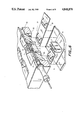
- FIG. 5 illustrates another preferred embodiment of the invention, this figure showing a patch panel connection having a back 39 and a front 40.
- a connector 11 includes the jaw segments 2 and the biasing ring springs 4 previously described.
- a first optical fiber 17 is illustrated as already installed within the connector 11.
- the optical fiber 17 is retained within a protective tube 15 which is connected to a first optical fiber contact 20.
- the contact 20 is retained in place by a back clamp 36 which has a flange 29 which engages a contact groove 19.
- the tool 26 includes an extension 27 which includes on a front end thereof the complementary means or collet 10 which in the embodiment illustrated again comprises a pyramid shaped member.
- the extension 27 is moveable in a direction of arrow 25 by utilizing hand moveable member 30, and the spring 28 moves the extension 27 in a direction opposite the arrow 25 when the member 30 is released.
- the tool 26 is inserted along a path indicated by dotted line 48 so as to urge locking clamp 33 downward against a force of spring 32.
- the spring 28 causes the collet 10 to urge the jaw segments 2 radially outward against the biasing force of rings 4.
- the optical fiber contact 21 is moved in a direction opposite the arrow 25 so as to insert the optical fiber 18 therewithin.
- an end of the optical fiber 18 abuts against an end of the optical fiber 17, and the tool is removed from the connector 11 which allows the locking clamp 33 to move upward in the drawing whereby locking mechanism 34 engages the optical fiber contact groove 19 so as to lock the contact housing 21 in place.
- the optical fiber 18 is clamped and aligned with the optical fiber 17 due to the biasing force generated by the rings 4 against the jaws 2.
- FIG. 6 illustrates an alternative embodiment of the invention whereby locking clamps 33 are urged into engagement with contact housing grooves 19 via a plurality of inline springs 31.
- the embodiment of FIG. 6 is most useful in an exposed connector panel requiring a plurality of adjacent connections, as illustrated in FIG. 7.
- FIGS. 6 and 7 A tool 41 most useful for connecting optical fibers in a panel such as that illustrated in FIG. 7 is illustrated in FIGS. 6 and 7.
- the tool includes first and second members 42, 43 which have pyramid collets 10 located on adjacent bottom sections thereof.
- the collets 10 are urged towards one another and hence into jaw entrances 13 by a force of spring 45.
- the members 42, 43 are held together via a bolt 44, as best illustrated in FIG. 6.
- tool handles 49, 50 are urged in the direction of arrows 46, 47 so that the collets 10 can be aligned with the jaw entrances 13, and then the handles 49, 50 are released which allows collets 10 to expand the jaw segments 2. Thereafter, first and second optical fibers 17, 18 are inserted into the contact through aperture 6 which extend through the collets 10, and subsequent to fiber insertion the tool is removed so as to allow the rings 4 to urge the jaw segments 2 into engagement with the optical fibers and hence align the claddings.
Abstract
Description
Claims (19)
Priority Applications (6)
| Application Number | Priority Date | Filing Date | Title |
|---|---|---|---|
| US07/178,115 US4848870A (en) | 1988-04-06 | 1988-04-06 | Optical fiber jaw connector |
| EP89905535A EP0408666A1 (en) | 1988-04-06 | 1989-04-04 | Optical fiber jaw connector |
| AU35575/89A AU624384B2 (en) | 1988-04-06 | 1989-04-04 | Optical fiber jaw connector |
| JP1505217A JPH03503687A (en) | 1988-04-06 | 1989-04-04 | fiber optic jaw connector |
| PCT/US1989/001413 WO1989009943A1 (en) | 1988-04-06 | 1989-04-04 | Optical fiber jaw connector |
| CA000595706A CA1306631C (en) | 1988-04-06 | 1989-04-05 | Optical fiber jaw connector |
Applications Claiming Priority (1)
| Application Number | Priority Date | Filing Date | Title |
|---|---|---|---|
| US07/178,115 US4848870A (en) | 1988-04-06 | 1988-04-06 | Optical fiber jaw connector |
Publications (1)
| Publication Number | Publication Date |
|---|---|
| US4848870A true US4848870A (en) | 1989-07-18 |
Family
ID=22651260
Family Applications (1)
| Application Number | Title | Priority Date | Filing Date |
|---|---|---|---|
| US07/178,115 Expired - Fee Related US4848870A (en) | 1988-04-06 | 1988-04-06 | Optical fiber jaw connector |
Country Status (6)
| Country | Link |
|---|---|
| US (1) | US4848870A (en) |
| EP (1) | EP0408666A1 (en) |
| JP (1) | JPH03503687A (en) |
| AU (1) | AU624384B2 (en) |
| CA (1) | CA1306631C (en) |
| WO (1) | WO1989009943A1 (en) |
Cited By (20)
| Publication number | Priority date | Publication date | Assignee | Title |
|---|---|---|---|---|
| WO1990005930A1 (en) * | 1988-11-17 | 1990-05-31 | Raychem Corporation | Optical fiber splice tray |
| US5127070A (en) * | 1991-02-07 | 1992-06-30 | Minnesota Mining And Manufacturing Company | Optical fiber distribution module |
| US5243673A (en) * | 1989-08-02 | 1993-09-07 | E. I. Du Pont De Nemours And Company | Opto-electronic component having positioned optical fiber associated therewith |
| US5287735A (en) * | 1990-12-10 | 1994-02-22 | Sensortech L.P. | Engine misfire or roughness detection method and apparatus |
| US5408558A (en) * | 1993-10-21 | 1995-04-18 | Litecom, Inc. | Connecting system with cleaved fiber and crimp termination |
| US5710851A (en) * | 1995-11-06 | 1998-01-20 | Amphenol Corporation | Strain relief system for a fiber optic connector |
| US5734770A (en) * | 1995-06-29 | 1998-03-31 | Minnesota Mining And Manufacturing Company | Cleave and bevel fiber optic connector |
| GB2318192A (en) * | 1996-07-15 | 1998-04-15 | Sumitomo Electric Industries | Optical fibre fixing device |
| US20030143349A1 (en) * | 1999-03-17 | 2003-07-31 | Nippon Sheet Glass Co., Ltd. | Method of manufacturing glass parts for connection of optical fibers, method of manufacturing mother glass to produce glass parts, and glass parts for connection of optical fibers |
| FR2841812A1 (en) * | 2002-07-08 | 2004-01-09 | Commissariat Energie Atomique | Fibre optic cable clamp unit has metal jaws with internal surface clamping deformable sheath between tapered ends |
| FR2841813A1 (en) * | 2002-07-08 | 2004-01-09 | Commissariat Energie Atomique | DEVICE FOR FASTENING A RIGID AND FRAGILE FIBER COMPRISING A MECHANICALLY DEFORMABLE SHEATH AND CAPABLE OF BEING SUBJECTED TO AT LEAST ONE MECHANICAL STRESS |
| US20040067028A1 (en) * | 2002-09-19 | 2004-04-08 | Mleczko Jamie A. | Termination ferrule for fiber optics |
| US20100130073A1 (en) * | 2008-11-21 | 2010-05-27 | Hobson Michael A | Test fixture with high-current electrical connection |
| US20140010514A1 (en) * | 2012-07-09 | 2014-01-09 | Avago Technologies General Ip (Singapore) Pte. Ltd. | Metal strain relief device for use in an optical communications system, an optical fiber cable that employs the strain relief device, and a method |
| US20140248021A1 (en) * | 2011-08-30 | 2014-09-04 | Opsens Inc. | Interface connector handle for disposable guidewire optical connection |
| US8845206B2 (en) | 2011-03-29 | 2014-09-30 | International Business Machines Corporation | Apparatus for plugging multiple connectors with spring loaded sleeves into an adapter simultaneously |
| US8950954B2 (en) | 2012-07-31 | 2015-02-10 | Avago Technologies General Ip ( Singapore) Pte. Ltd. | Side-edge mountable parallel optical communications module, an optical communications system that incorporates the module, and a method |
| US9054804B2 (en) | 2012-07-09 | 2015-06-09 | Avago Technologies General Ip (Singapore) Pte. Ltd. | Electromagnetic interference (EMI) shielding device and method for use in an optical communications system |
| US20160334206A1 (en) * | 2012-11-23 | 2016-11-17 | Airbus Operations S.A.S. | Strain measurement device and installation of such a device in an element |
| US20220236488A1 (en) * | 2019-06-03 | 2022-07-28 | Nippon Telegraph And Telephone Corporation | Optical Fiber Guide Structure and Optical Fiber Connecting Structure |
Families Citing this family (2)
| Publication number | Priority date | Publication date | Assignee | Title |
|---|---|---|---|---|
| JP2500523Y2 (en) * | 1991-03-18 | 1996-06-05 | 日本碍子株式会社 | Optical ferrule |
| JP6234243B2 (en) * | 2014-01-24 | 2017-11-22 | オリンパス株式会社 | Optical fiber connection adapter and endoscope apparatus |
Citations (17)
| Publication number | Priority date | Publication date | Assignee | Title |
|---|---|---|---|---|
| US4047796A (en) * | 1975-09-15 | 1977-09-13 | International Telephone And Telegraph Corporation | Precision optical fiber connector |
| DE2616876A1 (en) * | 1976-04-15 | 1977-10-20 | Siemens Ag | Bayonet-type connector for fibre optic cables - with cable ends positively centered in two connector halves using axial triangular-section guide passages |
| US4155624A (en) * | 1976-12-23 | 1979-05-22 | Thomas & Betts Corporation | Duplex optical fiber connector |
| US4253730A (en) * | 1977-11-17 | 1981-03-03 | Thomas & Betts Corporation | Optical fiber connector |
| US4279467A (en) * | 1979-11-05 | 1981-07-21 | International Telephone And Telegraph Corporation | Fiber optic connector |
| US4319802A (en) * | 1979-10-17 | 1982-03-16 | Bunker Ramo Corporation | Stain relief for fiber optic connectors |
| US4320938A (en) * | 1979-12-26 | 1982-03-23 | Bell Telephone Laboratories, Incorporated | Resilient optical fiber connector |
| US4339172A (en) * | 1979-03-31 | 1982-07-13 | Ferranti Limited | Connector having a single segmented deformable grip member for optical cables |
| US4354731A (en) * | 1979-10-02 | 1982-10-19 | E. I. Du Pont De Nemours And Company | Self-aligning optical fiber connector |
| US4421382A (en) * | 1980-04-01 | 1983-12-20 | Asahi Kogaku Kogyo Kabushiki Kaisha | Fiber retaining device for power laser |
| US4607911A (en) * | 1983-10-03 | 1986-08-26 | Conax Buffalo Corporation | Connector for an optical fiber having a stationary clamp engaged and operated by a rotatable member |
| US4639077A (en) * | 1983-07-21 | 1987-01-27 | Bbc Brown, Boveri & Company Limited | Coupling for a light-conducting fiber |
| US4645296A (en) * | 1984-12-20 | 1987-02-24 | Amp Incorporated | Optical fiber connector apparatus and method of manufacture |
| US4668045A (en) * | 1983-01-03 | 1987-05-26 | Gte Laboratories Incorporated | Optical fiber centering device |
| US4679895A (en) * | 1984-08-31 | 1987-07-14 | Amp Incorporated | Adhesiveless optical fiber connector |
| US4696537A (en) * | 1979-10-25 | 1987-09-29 | Allied Corporation | Connector for fiber optic cables |
| US4728171A (en) * | 1986-10-20 | 1988-03-01 | Amphenol Corporation | System for use in temporary repair of multiple fiber cable |
Family Cites Families (2)
| Publication number | Priority date | Publication date | Assignee | Title |
|---|---|---|---|---|
| DE2602661C3 (en) * | 1976-01-24 | 1981-01-08 | Felten & Guilleaume Carlswerk Ag, 5000 Koeln | Coupling device for optical fibers |
| NL184342C (en) * | 1978-05-05 | 1989-06-16 | Philips Nv | REMOVABLE COUPLING FOR LIGHT-CONDUCTING FIBERS. |
-
1988
- 1988-04-06 US US07/178,115 patent/US4848870A/en not_active Expired - Fee Related
-
1989
- 1989-04-04 AU AU35575/89A patent/AU624384B2/en not_active Ceased
- 1989-04-04 WO PCT/US1989/001413 patent/WO1989009943A1/en not_active Application Discontinuation
- 1989-04-04 EP EP89905535A patent/EP0408666A1/en not_active Withdrawn
- 1989-04-04 JP JP1505217A patent/JPH03503687A/en active Pending
- 1989-04-05 CA CA000595706A patent/CA1306631C/en not_active Expired - Fee Related
Patent Citations (17)
| Publication number | Priority date | Publication date | Assignee | Title |
|---|---|---|---|---|
| US4047796A (en) * | 1975-09-15 | 1977-09-13 | International Telephone And Telegraph Corporation | Precision optical fiber connector |
| DE2616876A1 (en) * | 1976-04-15 | 1977-10-20 | Siemens Ag | Bayonet-type connector for fibre optic cables - with cable ends positively centered in two connector halves using axial triangular-section guide passages |
| US4155624A (en) * | 1976-12-23 | 1979-05-22 | Thomas & Betts Corporation | Duplex optical fiber connector |
| US4253730A (en) * | 1977-11-17 | 1981-03-03 | Thomas & Betts Corporation | Optical fiber connector |
| US4339172A (en) * | 1979-03-31 | 1982-07-13 | Ferranti Limited | Connector having a single segmented deformable grip member for optical cables |
| US4354731A (en) * | 1979-10-02 | 1982-10-19 | E. I. Du Pont De Nemours And Company | Self-aligning optical fiber connector |
| US4319802A (en) * | 1979-10-17 | 1982-03-16 | Bunker Ramo Corporation | Stain relief for fiber optic connectors |
| US4696537A (en) * | 1979-10-25 | 1987-09-29 | Allied Corporation | Connector for fiber optic cables |
| US4279467A (en) * | 1979-11-05 | 1981-07-21 | International Telephone And Telegraph Corporation | Fiber optic connector |
| US4320938A (en) * | 1979-12-26 | 1982-03-23 | Bell Telephone Laboratories, Incorporated | Resilient optical fiber connector |
| US4421382A (en) * | 1980-04-01 | 1983-12-20 | Asahi Kogaku Kogyo Kabushiki Kaisha | Fiber retaining device for power laser |
| US4668045A (en) * | 1983-01-03 | 1987-05-26 | Gte Laboratories Incorporated | Optical fiber centering device |
| US4639077A (en) * | 1983-07-21 | 1987-01-27 | Bbc Brown, Boveri & Company Limited | Coupling for a light-conducting fiber |
| US4607911A (en) * | 1983-10-03 | 1986-08-26 | Conax Buffalo Corporation | Connector for an optical fiber having a stationary clamp engaged and operated by a rotatable member |
| US4679895A (en) * | 1984-08-31 | 1987-07-14 | Amp Incorporated | Adhesiveless optical fiber connector |
| US4645296A (en) * | 1984-12-20 | 1987-02-24 | Amp Incorporated | Optical fiber connector apparatus and method of manufacture |
| US4728171A (en) * | 1986-10-20 | 1988-03-01 | Amphenol Corporation | System for use in temporary repair of multiple fiber cable |
Cited By (32)
| Publication number | Priority date | Publication date | Assignee | Title |
|---|---|---|---|---|
| WO1990005930A1 (en) * | 1988-11-17 | 1990-05-31 | Raychem Corporation | Optical fiber splice tray |
| US5243673A (en) * | 1989-08-02 | 1993-09-07 | E. I. Du Pont De Nemours And Company | Opto-electronic component having positioned optical fiber associated therewith |
| US5287735A (en) * | 1990-12-10 | 1994-02-22 | Sensortech L.P. | Engine misfire or roughness detection method and apparatus |
| US5127070A (en) * | 1991-02-07 | 1992-06-30 | Minnesota Mining And Manufacturing Company | Optical fiber distribution module |
| US5408558A (en) * | 1993-10-21 | 1995-04-18 | Litecom, Inc. | Connecting system with cleaved fiber and crimp termination |
| US5734770A (en) * | 1995-06-29 | 1998-03-31 | Minnesota Mining And Manufacturing Company | Cleave and bevel fiber optic connector |
| US5710851A (en) * | 1995-11-06 | 1998-01-20 | Amphenol Corporation | Strain relief system for a fiber optic connector |
| US6018606A (en) * | 1996-07-15 | 2000-01-25 | Sumitomo Electric Industries, Ltd. | Fiber fixing device for linear lightguide |
| GB2318192B (en) * | 1996-07-15 | 2001-02-14 | Sumitomo Electric Industries | Fiber fixing device for linear lightguide |
| GB2318192A (en) * | 1996-07-15 | 1998-04-15 | Sumitomo Electric Industries | Optical fibre fixing device |
| US7007513B2 (en) * | 1999-03-17 | 2006-03-07 | Nippon Sheet Glass Co., Ltd. | Method of manufacturing glass parts for connection of optical fibers, method of manufacturing mother glass to produce glass parts, and glass parts for connection of optical fibers |
| US20030143349A1 (en) * | 1999-03-17 | 2003-07-31 | Nippon Sheet Glass Co., Ltd. | Method of manufacturing glass parts for connection of optical fibers, method of manufacturing mother glass to produce glass parts, and glass parts for connection of optical fibers |
| FR2841812A1 (en) * | 2002-07-08 | 2004-01-09 | Commissariat Energie Atomique | Fibre optic cable clamp unit has metal jaws with internal surface clamping deformable sheath between tapered ends |
| FR2841813A1 (en) * | 2002-07-08 | 2004-01-09 | Commissariat Energie Atomique | DEVICE FOR FASTENING A RIGID AND FRAGILE FIBER COMPRISING A MECHANICALLY DEFORMABLE SHEATH AND CAPABLE OF BEING SUBJECTED TO AT LEAST ONE MECHANICAL STRESS |
| WO2004007127A2 (en) * | 2002-07-08 | 2004-01-22 | Commissariat A L'energie Atomique | Device for fixing a rigid and brittle fiber comprising a mechanically deformable cladding and liable to be subjected to at least one mechanical stress |
| WO2004007127A3 (en) * | 2002-07-08 | 2004-04-08 | Commissariat Energie Atomique | Device for fixing a rigid and brittle fiber comprising a mechanically deformable cladding and liable to be subjected to at least one mechanical stress |
| US7167626B2 (en) * | 2002-07-08 | 2007-01-23 | Commissariat A L'energie Atomique | Device for fixing a rigid and brittle fiber comprising a mechanically deformable cladding and liable to be subjected to at least one mechanical stress |
| US20050232568A1 (en) * | 2002-07-08 | 2005-10-20 | Commissariat A L'energie Atomique | Device for fixing a rigid and brittle fiber comprising a mechanically deformable cladding and liable to be subjected to at least one mechanical stress |
| US6796722B2 (en) * | 2002-09-19 | 2004-09-28 | Yazaki North America, Inc. | Termination ferrule for fiber optics |
| US20040067028A1 (en) * | 2002-09-19 | 2004-04-08 | Mleczko Jamie A. | Termination ferrule for fiber optics |
| US20100130073A1 (en) * | 2008-11-21 | 2010-05-27 | Hobson Michael A | Test fixture with high-current electrical connection |
| US8302948B2 (en) * | 2008-11-21 | 2012-11-06 | Raytheon Company | Test fixture with high-current electrical connection |
| US8845206B2 (en) | 2011-03-29 | 2014-09-30 | International Business Machines Corporation | Apparatus for plugging multiple connectors with spring loaded sleeves into an adapter simultaneously |
| US9405075B2 (en) * | 2011-08-30 | 2016-08-02 | Opsens Inc. | Interface connector handle for disposable guidewire optical connection |
| US20140248021A1 (en) * | 2011-08-30 | 2014-09-04 | Opsens Inc. | Interface connector handle for disposable guidewire optical connection |
| US20140010514A1 (en) * | 2012-07-09 | 2014-01-09 | Avago Technologies General Ip (Singapore) Pte. Ltd. | Metal strain relief device for use in an optical communications system, an optical fiber cable that employs the strain relief device, and a method |
| US9054804B2 (en) | 2012-07-09 | 2015-06-09 | Avago Technologies General Ip (Singapore) Pte. Ltd. | Electromagnetic interference (EMI) shielding device and method for use in an optical communications system |
| US9304274B2 (en) * | 2012-07-09 | 2016-04-05 | Avago Technologies General Ip (Singapore) Pte. Ltd. | Metal strain relief device for use in an optical communications system, an optical fiber cable that employs the strain relief device, and a method |
| US8950954B2 (en) | 2012-07-31 | 2015-02-10 | Avago Technologies General Ip ( Singapore) Pte. Ltd. | Side-edge mountable parallel optical communications module, an optical communications system that incorporates the module, and a method |
| US20160334206A1 (en) * | 2012-11-23 | 2016-11-17 | Airbus Operations S.A.S. | Strain measurement device and installation of such a device in an element |
| US10345097B2 (en) * | 2012-11-23 | 2019-07-09 | Airbus Operations S.A.S. | Strain measurement device and installation of such a device in an element |
| US20220236488A1 (en) * | 2019-06-03 | 2022-07-28 | Nippon Telegraph And Telephone Corporation | Optical Fiber Guide Structure and Optical Fiber Connecting Structure |
Also Published As
| Publication number | Publication date |
|---|---|
| WO1989009943A1 (en) | 1989-10-19 |
| JPH03503687A (en) | 1991-08-15 |
| AU3557589A (en) | 1989-11-03 |
| CA1306631C (en) | 1992-08-25 |
| AU624384B2 (en) | 1992-06-11 |
| EP0408666A1 (en) | 1991-01-23 |
Similar Documents
| Publication | Publication Date | Title |
|---|---|---|
| US4848870A (en) | Optical fiber jaw connector | |
| US4190316A (en) | Lens connector for optical fibers | |
| AU720684B2 (en) | Fiber optic cable connector apparatus and method | |
| EP0195432B1 (en) | Optical connector | |
| US4898446A (en) | Optical fiber connector | |
| US5179608A (en) | Connector for optical fiber | |
| RU2103772C1 (en) | Gear joining first and second parts of underwater connector | |
| JPS62501588A (en) | Connecting mechanism for connectors | |
| CA2676022C (en) | Electrical splice connector | |
| JPH073494B2 (en) | Fiber optic connector | |
| EP0547778A1 (en) | Hermaphroditic connector for single fiber optical cable | |
| CA1288266C (en) | Device and process for spreading optical fibers emerging from a cable to be connected | |
| JPH05119233A (en) | Connector for quick locking and unlocking type optical fiber | |
| GB2060197A (en) | Optical fibre connector | |
| NZ247693A (en) | Optical fibre connector | |
| US4208093A (en) | Fiber optic ferrule and method of terminating same to a cable | |
| EP1072914A3 (en) | Optical fiber connector tuning tool for eccentricity optimisation | |
| WO1984000617A1 (en) | Electromagnetic energy signal-carrying connector having secure strain-relief mechanism | |
| GB2068490A (en) | Hydraulic coupling device | |
| US5550944A (en) | Fibre optic connector | |
| GB2032130A (en) | Fibre optic connectors | |
| US4867523A (en) | Optical fiber connector including serpentine grooved member actuated by longitudinal forces | |
| GB1587233A (en) | Clamp for conductor of an overhead electricity transmission line | |
| EP0989428A1 (en) | Optical fibre ferrule | |
| GB2311621A (en) | Connector with rotatable sleeve and separated clamps |
Legal Events
| Date | Code | Title | Description |
|---|---|---|---|
| AS | Assignment |
Owner name: RAYCHEM CORPORATION, 300 CONSTITUTION DRIVE, MENLO Free format text: ASSIGNMENT OF ASSIGNORS INTEREST.;ASSIGNORS:WISECARVER, MARTIN L.;TAYEB, ABDUL;REEL/FRAME:004894/0323 Effective date: 19880606 Owner name: RAYCHEM CORPORATION, CALIFORNIA Free format text: ASSIGNMENT OF ASSIGNORS INTEREST;ASSIGNORS:WISECARVER, MARTIN L.;TAYEB, ABDUL;REEL/FRAME:004894/0323 Effective date: 19880606 |
|
| FPAY | Fee payment |
Year of fee payment: 4 |
|
| CC | Certificate of correction | ||
| FPAY | Fee payment |
Year of fee payment: 8 |
|
| REMI | Maintenance fee reminder mailed | ||
| LAPS | Lapse for failure to pay maintenance fees | ||
| FP | Lapsed due to failure to pay maintenance fee |
Effective date: 20010718 |
|
| STCH | Information on status: patent discontinuation |
Free format text: PATENT EXPIRED DUE TO NONPAYMENT OF MAINTENANCE FEES UNDER 37 CFR 1.362 |