US4842393A - Cuspated lens - Google Patents

Cuspated lens Download PDF

Info

Publication number
US4842393A
US4842393A US07/071,493 US7149387A US4842393A US 4842393 A US4842393 A US 4842393A US 7149387 A US7149387 A US 7149387A US 4842393 A US4842393 A US 4842393A
Authority
US
United States
Prior art keywords
axis
radiation
front surface
lens
periphery
Prior art date
Legal status (The legal status is an assumption and is not a legal conclusion. Google has not performed a legal analysis and makes no representation as to the accuracy of the status listed.)
Expired - Fee Related
Application number
US07/071,493
Inventor
Michael A. Gorman
Mark H. Sterling
Robert M. Kiehn
Lowell T. Wood
Current Assignee (The listed assignees may be inaccurate. Google has not performed a legal analysis and makes no representation or warranty as to the accuracy of the list.)
HOUSTON-UNIVERSITY PARK CHAPTER 111 TEXAS EDUCATION CODE, University of
University of Houston
Original Assignee
University of Houston
Priority date (The priority date is an assumption and is not a legal conclusion. Google has not performed a legal analysis and makes no representation as to the accuracy of the date listed.)
Filing date
Publication date
Application filed by University of Houston filed Critical University of Houston
Priority to US07/071,493 priority Critical patent/US4842393A/en
Assigned to UNIVERSITY OF HOUSTON-UNIVERSITY PARK, CHAPTER 111, TEXAS EDUCATION CODE reassignment UNIVERSITY OF HOUSTON-UNIVERSITY PARK, CHAPTER 111, TEXAS EDUCATION CODE ASSIGNMENT OF ASSIGNORS INTEREST. Assignors: KIEHN, ROBERT M., WOOD, LOWELL T., GORMAN, MICHAEL A., STERLING, MARK H.
Priority to US07/160,164 priority patent/US4834484A/en
Application granted granted Critical
Publication of US4842393A publication Critical patent/US4842393A/en
Anticipated expiration legal-status Critical
Expired - Fee Related legal-status Critical Current

Links

Images

Classifications

    • GPHYSICS
    • G02OPTICS
    • G02BOPTICAL ELEMENTS, SYSTEMS OR APPARATUS
    • G02B6/00Light guides; Structural details of arrangements comprising light guides and other optical elements, e.g. couplings
    • G02B6/24Coupling light guides
    • G02B6/26Optical coupling means
    • G02B6/28Optical coupling means having data bus means, i.e. plural waveguides interconnected and providing an inherently bidirectional system by mixing and splitting signals
    • GPHYSICS
    • G02OPTICS
    • G02BOPTICAL ELEMENTS, SYSTEMS OR APPARATUS
    • G02B5/00Optical elements other than lenses
    • G02B5/001Axicons, waxicons, reflaxicons
    • GPHYSICS
    • G02OPTICS
    • G02BOPTICAL ELEMENTS, SYSTEMS OR APPARATUS
    • G02B6/00Light guides; Structural details of arrangements comprising light guides and other optical elements, e.g. couplings
    • G02B6/24Coupling light guides
    • G02B6/26Optical coupling means
    • G02B6/28Optical coupling means having data bus means, i.e. plural waveguides interconnected and providing an inherently bidirectional system by mixing and splitting signals
    • G02B6/2804Optical coupling means having data bus means, i.e. plural waveguides interconnected and providing an inherently bidirectional system by mixing and splitting signals forming multipart couplers without wavelength selective elements, e.g. "T" couplers, star couplers
    • G02B6/2848Optical coupling means having data bus means, i.e. plural waveguides interconnected and providing an inherently bidirectional system by mixing and splitting signals forming multipart couplers without wavelength selective elements, e.g. "T" couplers, star couplers having refractive means, e.g. imaging elements between light guides as splitting, branching and/or combining devices, e.g. lenses, holograms
    • GPHYSICS
    • G02OPTICS
    • G02BOPTICAL ELEMENTS, SYSTEMS OR APPARATUS
    • G02B6/00Light guides; Structural details of arrangements comprising light guides and other optical elements, e.g. couplings
    • G02B6/24Coupling light guides
    • G02B6/26Optical coupling means
    • G02B6/32Optical coupling means having lens focusing means positioned between opposed fibre ends
    • GPHYSICS
    • G02OPTICS
    • G02BOPTICAL ELEMENTS, SYSTEMS OR APPARATUS
    • G02B6/00Light guides; Structural details of arrangements comprising light guides and other optical elements, e.g. couplings
    • G02B6/24Coupling light guides
    • G02B6/36Mechanical coupling means
    • G02B6/3604Rotary joints allowing relative rotational movement between opposing fibre or fibre bundle ends

Definitions

  • This invention relates to a cuspate refractive device having a maximum slope magnitude inside the periphery of the device which decreases toward the periphery, and particularly to a cuspate lens which focuses radiation into a ring or which produces an annular beam of parallel radiation.
  • the invention also relates to a fiber optic coupler and an optical slip ring employing such a cuspate lens.
  • Laser cutting in which a high intensity beam of radiation is employed to cut an object is well known. Such techniques are widely employed, for example, in surgical techniques. Such laser cutting heretofore has suffered from drawbacks in that, to cut the object at more than the entry or focusing point of the laser beam, it has been necessary to move either the object or the laser beam generating source to trace the desired path of the cut in the object. This is particularly disadvantageous when using powerful laser sources which are typically large, heavy and fragile or otherwise sensitive to movement, and/or when the object to be cut is also large and/or heavy. Further, such cutting is not instantaneous because of the time it takes to effect the movement of the laser and/or object being cut. Thus, there is a need, heretofore unfilled as far as Applicants are aware, for a device to permit the desired laser cutting instantaneously without having to move the laser source or the object to be cut.
  • Couplers for optical fibers in which light is transmitted between one optical fiber and one or more other optical fibers are also well known.
  • optic couplers heretofore known have suffered from a drawback in that it has been necessary to fuse the fibers together. Once the fibers are fused, it is difficult to take them apart. Also, it has been difficult to ensure that each fiber receives the same fraction of the incident light.
  • an optical coupler in which it is not necessary to fuse the optical fibers and in which each fiber receives the same fraction of incident light.
  • the present invention provides a refractive device for transmitting radiation in a selected geometric pattern, such as, for example, a ring or a line, or a plurality of rings or lines.
  • the device includes a central longitudinal axis and a periphery in spaced relation thereto.
  • a front surface extends laterally from the axis to the periphery for receiving radiation oriented parallel with respect to the axis.
  • the front surface has a cusp at least at the axis, and a maximum slope magnitude inside the periphery and a slope magnitude which decreases from the cusp toward the periphery for refracting radiation away from the axis.
  • a rear surface transmits the refracted radiation from the device.
  • a lens for focusing radiation into a ring at a focal plane includes a central longitudinal axis and a periphery in spaced relation thereto.
  • a front surface which is radially symmetric with respect to the axis extends laterally therefrom to the periphery for receiving radiation oriented parallel with respect to the axis.
  • the front surface has a cusp at the axis, a maximum slope magnitude at the cusp, a decreasing slope magnitude from the cusp to the periphery and a geometry for focusing the radiation at a focal plane away from an area bounded by a circle concentric with the axis and into a ring around the circle.
  • the lens has a rear surface for transmitting the radiation therefrom.
  • the focal plane may be disposed in front of or behind the rear surface.
  • a lens for producing an annular beam of radiation includes a central longitudinal axis and a periphery in spaced relation thereto.
  • a front surface which is radially symmetric with respect to the axis extends laterally therefrom to the periphery for receiving radiation oriented parallel with respect to the axis.
  • the front surface has a cusp at the axis, a maximum slope magnitude at the cusp, a decreasing slope magnitude from the cusp to the periphery and a geometry for refracting the radiation away from the axis.
  • the lens has a rear surface with a geometry for orienting the refracted radiation parallel with respect to the axis and transmitting the radiation from the lens in an annular beam.
  • a further aspect of the invention provides a lens made of a transmissive material for conservatively focusing radiation at a focal plane into a ring around a central area from which the focused radiation is excluded.
  • the lens includes a central longitudinal axis and a periphery in spaced relation thereto.
  • the lens has a front surface extending laterally from the axis to the periphery for receiving radiation oriented parallel with respect to the axis.
  • the front surface is radially symmetric with respect to the axis, and has a cusp and a maximum slope magnitude at the axis. The slope magnitude decreases from the cusp to a minimum at the periphery for refracting the radiation away from the axis.
  • the lens has a flat rear surface normal to the axis for transmitting the refracted radiation from the lens.
  • the front surface has a functional profile essentially according to the equation:
  • f(r) is the functional form of the front surface
  • r is the radial distance from the axis
  • t is the thickness of the lens from the rear surface to the front surface at its periphery
  • D is the focal distance from the rear surface to the focal plane
  • n is the refractive index of the lens
  • is an angle according to the equation:
  • f'(r) is the first derivative of f(r) with respect to r
  • is an angle according to the equation
  • OPL is the optical path length according to the equation:
  • a still further aspect of the invention provides an optical fiber coupler including means for receiving a transmissive end of a first optical fiber, means for receiving transmissive ends of a plurality of second optical fibers in a circular arrangement and defining a ring with a radial width corresponding to a transverse dimension of the second optical fibers, and means including a cuspate lens for conservatively transmitting light between the end of the first optical fiber and the ring.
  • the cuspate lens of the invention is also useful in an optical slip ring having at least two channels.
  • the slip ring includes first and second opposed housings rotatable with respect to each other about a common axis.
  • a first channel includes a first channel optical fiber and first channel beam spreader transmissively associated therewith in each housing.
  • the first channel beam spreaders are coaxially aligned with the axis and transmissively opposed in the respective housings.
  • a second channel includes a second channel optical fiber, and a second channel beam spreader and a cuspate lens transmissively associated therewith in each respective housing.
  • the second channel beam spreaders are coaxially aligned with the axis and transmissively disposed between a respective second channel optical fiber and a respective cuspate lens.
  • the lenses each have a cuspate front surface for receiving light from a respective second channel beam spreader and a rear surface for transmitting the received light into an annular beam around the first channel beam spreaders.
  • the rear surfaces of the cuspate lenses are transmissively opposed in their respective housings.
  • FIG. 1 is a perspective view of a lens according to the present invention
  • FIG. 2 is a schematic view, partly in cross-section, of the lens of FIG. 1 receiving light from a parallel light source as seen along the lines 2--2.
  • FIG. 3 is a schematic view, partly in cross-section, of a radially symmetric lens with an annular focal plane according to the present invention
  • FIG. 4 is a schematic cross-sectional view of a radially symmetric lens producing an annular beam according to the present invention
  • FIG. 5 is a schematic cross-sectional view of the lens of FIG. 3 illustrating variables in the optical path length equation
  • FIGS. 6A and 6B are schematic cross-sectional views of the lens of FIG. 4 illustrating a theoretical model for calculation of the lens surface profiles
  • FIG. 7 is a schematic cross-sectional view of a fiber optic coupler using a lens of the present invention.
  • FIG. 8 is a plan view of the device of FIG. 7 as seen along the lines 8--8;
  • FIG. 9 is a schematic cross-sectional view of a two-channel optic slip ring using a lens of the present invention.
  • the refractive device of the present invention is contemplated as being useful for the transmission of one or more types of radiation, such as, for example, gamma rays, X-rays, ultraviolet rays, visible light rays, infrared, microwaves, radio waves, sound and ultrasound waves, and the like.
  • radiation also broadly includes beams of particles, such as, for example, electrons, protons, neutrons, alpha particles and the like.
  • the refractive device is generally made of a material transmissive to the type of radiation desired to be transmitted therethrough. Such materials are known in the art. For convenience, reference is made herein to light and visible light rays for exemplary purposes, but it is to be understood that the refractive device may be suitable for other types of radiation as well, depending on the materials of construction.
  • slope magnitude is the absolute value of the slope of a lens surface, e.g. the variation of the lens surface dimension taken in a direction parallel to a reference axis or plane with respect to the variation in dimension in a direction normal to the reference.
  • conventional concave and convex lens surfaces have a slope magnitude of zero at the center which increases to a maximum slope magnitude at their periphery.
  • the front surface of the refractive device of the present invention has a maximum slope magnitude inside the area boundary by the periphery, preferably adjacent the cusp, and especially at the cusp, and a slope magnitude which decreases in a direction from the cusp toward the periphery for at least a portion of the distance from the cusp toward the periphery, preferably to a minimum slope magnitude at the periphery, and especially decreasing essentially over the entire distance from the cusp to the periphery.
  • the term "cusp" is used in the sense of a fixed point on a mathematical curve at which a point tracing the curve would essentially reverse its direction of motion, i.e. the sign of the slope changes and is discontinuous at the cusp.
  • the cusp of the front surface of the refractive device is located at least at the longitudinal axis of the device.
  • the cusp may be, for example, a point at the center of a radially symmetric, circular lens, or at the center of an elliptically shaped lens.
  • the cusp may be a straight line in a lens symmetric with respect to a plane passing through the line, or a curve in an asymmetric refractive device.
  • the refractive device is symmetric.
  • the lens may be radially symmetric with respect to the cusp to generally focus light away from the axis passing through the cusp into a ring at a focal plane around a darkened central area.
  • the lens may have an elliptical periphery and be symmetric with respect to a plane containing the axially aligned cusp to generally focus light at a focal plane, away from an elliptical area into an elliptical ring around the darkened elliptical central area.
  • the device may have a front surface with a linear cusp extending from one peripheral side to an opposite peripheral side and be symmetric with respect to the cusp to focus incident radiation at a focal plane into two parallel lines away from the area between the parallel lines.
  • essentially all of the parallel incident light entering the front surface of the refractive device is transmitted through the rear surface.
  • the present device conserves the incident light and focuses or refracts essentially all of the light to the periphery of the area from which the transmitted light is excluded.
  • a refractive device or lens 100 made by conventional lens manufacturing techniques such as lathing or molding of an optically transmissive material such as, for example, glass, polymethylmethacrylate or the like.
  • the lens 100 has a central longitudinal axis 102, a front surface 104, and rear surface 106.
  • the front surface 104 extends laterally from axis 102 toward periphery 108 and is radially symmetric with respect to axis 102.
  • the surface 104 has a cusp 110 at axis 102. The slope magnitude is greatest at the cusp 110 and decreases from the cusp 110 to a minimum at the periphery 108.
  • the lens 100 receives incident light I 0 oriented parallel with respect to axis 102.
  • the light I 0 is bent or refracted at the front surface 104.
  • the path through lens 100 of the light I 0 refracted at surface 104 depends on the angle of the surface 104 through which the light I 0 is received and the refractive index of the lens material.
  • the decreasing slope magnitude of the surface 104 generally refracts the light I 0 away from the axis 102.
  • path A followed by the light I 0 received at the surface 104 adjacent the cusp 110 is bent more sharply away from the axis 102 than the light I 0 received at the surface 104 adjacent the periphery 108 which follows a path B substantially parallel to axis 102.
  • the result is that the light E transmitted through the surface 106 is generally refracted away from the axis 102 producing a darkened central circle 112 from which the light E is generally excluded and a generally bright ring 114.
  • the lens 100 may or may not have a focal plane, depending on the geometry of the front surface 104, the refractive properties of the material of which the lens 100 is made, and the geometry of rear surface 106.
  • FIG. 3 there is illustrated a radially symmetric lens 300 having an axis 302, front surface 304, rear surface 306, periphery 308 and cusp 310 essentially as described above with reference to FIGS. 1 and 2.
  • the geometry of surface 304 is designed to focus the incident light I 0 into ring or annulus 320 at focal plane 322.
  • the focal plane 322 may be axially disposed as desired.
  • OPL is the optical path length
  • t is the thickness of the lens at the periphery
  • f(r) is the functional form of the surface
  • n is the refractive index
  • is the angle of the path of the ray inside the lens to the lens axis
  • Equation (4) is difficult to solve mathematically, but its solution can be approximated by numerical methods.
  • An exemplary Fortran computer program for numerically solving equation (4) is as follows:
  • a cuspate lens was fabricated by machining a polymethacrylate block obtained under the trade designation PLEXIGLAS by a computer-aided lathing process to conform to the profile generated by this program.
  • the resulting lens had a radius of 20 mm, a thickness of 25 mm, a focal distance of 50 mm from the rear surface and a focusing ring width of about 1 mm.
  • the radially symmetric cuspate lens 400 has an axis 402, front surface 404, rear surface 406, periphery 408 and cusp 410 essentially as described above with reference to FIG. 3.
  • the front surface 404 has a geometry such that the incident light I 0 is refracted to an annular section 412 of the rear surface 406.
  • the annular section 412 has a slope geometrically similar to that of the front surface 404 so that the light E is emitted therefrom oriented in the same direction as the incident light I 0 , i.e. parallel to axis 402.
  • the lens 400 produces an annular beam 414.
  • a Fortran computer program based on geometric ray tracing equations as illustrated in FIG. 6 for the radially symmetric cuspate lens 400 of FIG. 4 producing an annular beam is as follows:
  • a cuspate lens producing an annular beam is fabricated by machining a polymethacrylate block to conform to this profile.
  • the resulting lens has a radius of 20 mm, a thickness of 40 mm and produces an annular beam with an inside radius of about 12.4 mm and an outside radius of 20 mm.
  • the refractive device of the present invention has many contemplated utilities, such as, in decorative indoor lighting in which the cuspate lens is used as a transmissive surface for natural and artificial light sources.
  • the cuspate lens is also contemplated as being useful in laser cutting and laser surgery in which the cutting line is in the form of a circle, ellipse, straight line or the like.
  • Use of a cuspate lens for focusing the laser source into a ring at a focal plane obviates the necessity of moving either the laser source or the object being cut and facilitates an essentially instantaneous laser cut.
  • the cuspate lens is also useful in a fiber optic coupler and in an optical slip ring.
  • a fiber optic coupler 500 employing a cuspate lens 502.
  • the coupler 500 has a housing 504 with a first fiber optic receiving end 506 and a second fiber optic receiving end 508.
  • a source fiber optic 510 is received along a central longitudinal axis 512 in a conventional fiber optic receiver 514.
  • a beam spreader 516 is positioned to spread light emitted by the fiber optic 510 into a parallel oriented beam of generally circular cross-section. As shown, the beam spreader 516 comprises first biconvex lens 518 and second biconvex lens 520 coaxially positioned in spaced relation thereto.
  • the beam spreader 516 could be a rod device with a refractive index gradient such as that available from Melles Griot.
  • the lens 502 is disposed in the device 500 to receive a beam of light from the beam spreader 516 at the cuspate surface 522 such that the beam is coaxial with a central longitudinal axis 524 of the lens 502.
  • the lens 502 is designed to focus light into a ring or annulus 525 on second fiber optic receiving end 508 in which a plurality of second fiber optics 526 are received.
  • the fiber optic coupler 500 receives an optical signal via the fiber optic 510 which is enlarged in the beam spreader 516.
  • the beam from the beam spreader 516 is received by the cuspate lens 502 and focused to the ring 525 where the light is received by each of the optical fibers 526 and transmitted thereby.
  • each fiber 526 receives the same fraction of incident light.
  • light signals can be transmitted from the fibers 526 to the fiber 510 via the same mechanism.
  • each of the transmissive ends of the optical fibers 510 and 526 be cut at a right angle as is well known in the art.
  • any number of the second optical fibers can be employed, up to the number which the endplate 508 is designed to receive.
  • the optical fibers 510 and 526 can be readily removed and/or inserted in the respective receiving ends 506 and 508 since they are mechanically attached rather than welded.
  • the device 500 can also be used as an optic slip ring by, for example, permitting the end 508 to rotate with respect to the housing 504.
  • the end 508 is positioned on a stationary platform and the housing 504 on a platform rotating with respect thereto about the axes 512 and 524, or vice versa.
  • the slip ring 600 has a first housing 608 positioned on a rotating platform (not shown) rotating around an axis 610, and a second housing 612 positioned on a stationary or rotating platform (not shown) such that the housings 608 and 612 rotate with respect to each other.
  • a fiber optic 616 is positioned to transmit light to and/or receive light from a beam spreader 618 coaxial with the axis 610.
  • a corresponding coaxial beam spreader 620 is positioned to receive light emitted from and/or transmit light to beam spreader 618, and which is transmissively connected to optical fiber 621.
  • the beam spreaders 618 and 620 are, for example, rod lenses with a graded index of refraction such as those available from Melles Griot.
  • a second channel is provided in the first housing including optical fiber 622, beam spreader 624 and cuspate lens 602 coaxially aligned to send and/or receive light in an annulus 626 around the beam spreader 618.
  • the corresponding second channel in the second housing 612 is similarly provided with cuspate lens 604, beam spreader 628 and optical fiber 630.
  • additional channels can be provided by using cuspate lenses which are progressively larger in diameter. Light losses resulting from the fiber optic(s) passing from outside the housings through the transmission annulus of the second channel (and any additional channels) are minimal.

Abstract

A cuspate lens is disclosed having a slope magnitude which decreases from a maximum at a central cusp to a minimum at the periphery. A radially symmetric version of the lens can focus light into a ring, or produce an annular beam. Also disclosed are a fiber optic coupler and an optical slip ring using the cuspated lenses.

Description

The invention described herein was made in the course of, or under a contract with the Office of Naval Research, and the Government has certain rights in the invention.
FIELD OF THE INVENTION
This invention relates to a cuspate refractive device having a maximum slope magnitude inside the periphery of the device which decreases toward the periphery, and particularly to a cuspate lens which focuses radiation into a ring or which produces an annular beam of parallel radiation. The invention also relates to a fiber optic coupler and an optical slip ring employing such a cuspate lens.
BACKGROUND OF THE INVENTION
Laser cutting in which a high intensity beam of radiation is employed to cut an object is well known. Such techniques are widely employed, for example, in surgical techniques. Such laser cutting heretofore has suffered from drawbacks in that, to cut the object at more than the entry or focusing point of the laser beam, it has been necessary to move either the object or the laser beam generating source to trace the desired path of the cut in the object. This is particularly disadvantageous when using powerful laser sources which are typically large, heavy and fragile or otherwise sensitive to movement, and/or when the object to be cut is also large and/or heavy. Further, such cutting is not instantaneous because of the time it takes to effect the movement of the laser and/or object being cut. Thus, there is a need, heretofore unfilled as far as Applicants are aware, for a device to permit the desired laser cutting instantaneously without having to move the laser source or the object to be cut.
Couplers for optical fibers in which light is transmitted between one optical fiber and one or more other optical fibers are also well known. However, such optic couplers heretofore known have suffered from a drawback in that it has been necessary to fuse the fibers together. Once the fibers are fused, it is difficult to take them apart. Also, it has been difficult to ensure that each fiber receives the same fraction of the incident light. Thus, there is a need for an optical coupler in which it is not necessary to fuse the optical fibers and in which each fiber receives the same fraction of incident light.
SUMMARY OF THE INVENTION
The present invention provides a refractive device for transmitting radiation in a selected geometric pattern, such as, for example, a ring or a line, or a plurality of rings or lines. The device includes a central longitudinal axis and a periphery in spaced relation thereto. A front surface extends laterally from the axis to the periphery for receiving radiation oriented parallel with respect to the axis. The front surface has a cusp at least at the axis, and a maximum slope magnitude inside the periphery and a slope magnitude which decreases from the cusp toward the periphery for refracting radiation away from the axis. A rear surface transmits the refracted radiation from the device.
In another aspect, there is provided a lens for focusing radiation into a ring at a focal plane. The lens includes a central longitudinal axis and a periphery in spaced relation thereto. A front surface which is radially symmetric with respect to the axis extends laterally therefrom to the periphery for receiving radiation oriented parallel with respect to the axis. The front surface has a cusp at the axis, a maximum slope magnitude at the cusp, a decreasing slope magnitude from the cusp to the periphery and a geometry for focusing the radiation at a focal plane away from an area bounded by a circle concentric with the axis and into a ring around the circle. The lens has a rear surface for transmitting the radiation therefrom. The focal plane may be disposed in front of or behind the rear surface.
In still another aspect, there is provided a lens for producing an annular beam of radiation. The lens includes a central longitudinal axis and a periphery in spaced relation thereto. A front surface which is radially symmetric with respect to the axis extends laterally therefrom to the periphery for receiving radiation oriented parallel with respect to the axis. The front surface has a cusp at the axis, a maximum slope magnitude at the cusp, a decreasing slope magnitude from the cusp to the periphery and a geometry for refracting the radiation away from the axis. The lens has a rear surface with a geometry for orienting the refracted radiation parallel with respect to the axis and transmitting the radiation from the lens in an annular beam.
A further aspect of the invention provides a lens made of a transmissive material for conservatively focusing radiation at a focal plane into a ring around a central area from which the focused radiation is excluded. The lens includes a central longitudinal axis and a periphery in spaced relation thereto. The lens has a front surface extending laterally from the axis to the periphery for receiving radiation oriented parallel with respect to the axis. The front surface is radially symmetric with respect to the axis, and has a cusp and a maximum slope magnitude at the axis. The slope magnitude decreases from the cusp to a minimum at the periphery for refracting the radiation away from the axis. The lens has a flat rear surface normal to the axis for transmitting the refracted radiation from the lens. The front surface has a functional profile essentially according to the equation:
f(r)=[OPL-t-Dsecξ]/[nsecγ-1],
wherein f(r) is the functional form of the front surface, r is the radial distance from the axis, t is the thickness of the lens from the rear surface to the front surface at its periphery, D is the focal distance from the rear surface to the focal plane, n is the refractive index of the lens, γ is an angle according to the equation:
γ=tan.sup.-1 [f'(r)]-sin.sup.-1 {[sin (tan.sup.-1 [f'(r)])]/n},
wherein f'(r) is the first derivative of f(r) with respect to r, ξ is an angle according to the equation
ξ=sin.sup.-1 (n sin γ),
and OPL is the optical path length according to the equation:
OPL=[t-f(r)]+n[f(r)/cos γ]+[D/cos ξ].
A still further aspect of the invention provides an optical fiber coupler including means for receiving a transmissive end of a first optical fiber, means for receiving transmissive ends of a plurality of second optical fibers in a circular arrangement and defining a ring with a radial width corresponding to a transverse dimension of the second optical fibers, and means including a cuspate lens for conservatively transmitting light between the end of the first optical fiber and the ring.
The cuspate lens of the invention is also useful in an optical slip ring having at least two channels. The slip ring includes first and second opposed housings rotatable with respect to each other about a common axis. A first channel includes a first channel optical fiber and first channel beam spreader transmissively associated therewith in each housing. The first channel beam spreaders are coaxially aligned with the axis and transmissively opposed in the respective housings. A second channel includes a second channel optical fiber, and a second channel beam spreader and a cuspate lens transmissively associated therewith in each respective housing. The second channel beam spreaders are coaxially aligned with the axis and transmissively disposed between a respective second channel optical fiber and a respective cuspate lens. The lenses each have a cuspate front surface for receiving light from a respective second channel beam spreader and a rear surface for transmitting the received light into an annular beam around the first channel beam spreaders. The rear surfaces of the cuspate lenses are transmissively opposed in their respective housings.
BRIEF DESCRIPTION OF THE DRAWINGS
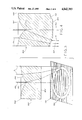
FIG. 1 is a perspective view of a lens according to the present invention;
FIG. 2 is a schematic view, partly in cross-section, of the lens of FIG. 1 receiving light from a parallel light source as seen along the lines 2--2.
FIG. 3 is a schematic view, partly in cross-section, of a radially symmetric lens with an annular focal plane according to the present invention;
FIG. 4 is a schematic cross-sectional view of a radially symmetric lens producing an annular beam according to the present invention;
FIG. 5 is a schematic cross-sectional view of the lens of FIG. 3 illustrating variables in the optical path length equation;
FIGS. 6A and 6B are schematic cross-sectional views of the lens of FIG. 4 illustrating a theoretical model for calculation of the lens surface profiles;
FIG. 7 is a schematic cross-sectional view of a fiber optic coupler using a lens of the present invention;
FIG. 8 is a plan view of the device of FIG. 7 as seen along the lines 8--8; and
FIG. 9 is a schematic cross-sectional view of a two-channel optic slip ring using a lens of the present invention.
DETAILED DESCRIPTION OF THE INVENTION
The refractive device of the present invention is contemplated as being useful for the transmission of one or more types of radiation, such as, for example, gamma rays, X-rays, ultraviolet rays, visible light rays, infrared, microwaves, radio waves, sound and ultrasound waves, and the like. As used herein, the term "radiation" also broadly includes beams of particles, such as, for example, electrons, protons, neutrons, alpha particles and the like. The refractive device is generally made of a material transmissive to the type of radiation desired to be transmitted therethrough. Such materials are known in the art. For convenience, reference is made herein to light and visible light rays for exemplary purposes, but it is to be understood that the refractive device may be suitable for other types of radiation as well, depending on the materials of construction.
As used herein, the term "slope magnitude" is the absolute value of the slope of a lens surface, e.g. the variation of the lens surface dimension taken in a direction parallel to a reference axis or plane with respect to the variation in dimension in a direction normal to the reference. Thus, conventional concave and convex lens surfaces have a slope magnitude of zero at the center which increases to a maximum slope magnitude at their periphery. In contrast, the front surface of the refractive device of the present invention has a maximum slope magnitude inside the area boundary by the periphery, preferably adjacent the cusp, and especially at the cusp, and a slope magnitude which decreases in a direction from the cusp toward the periphery for at least a portion of the distance from the cusp toward the periphery, preferably to a minimum slope magnitude at the periphery, and especially decreasing essentially over the entire distance from the cusp to the periphery.
As used herein, the term "cusp" is used in the sense of a fixed point on a mathematical curve at which a point tracing the curve would essentially reverse its direction of motion, i.e. the sign of the slope changes and is discontinuous at the cusp. The cusp of the front surface of the refractive device is located at least at the longitudinal axis of the device. The cusp may be, for example, a point at the center of a radially symmetric, circular lens, or at the center of an elliptically shaped lens. Alternatively, the cusp may be a straight line in a lens symmetric with respect to a plane passing through the line, or a curve in an asymmetric refractive device.
Preferably, the refractive device is symmetric. For example, the lens may be radially symmetric with respect to the cusp to generally focus light away from the axis passing through the cusp into a ring at a focal plane around a darkened central area. Or, the lens may have an elliptical periphery and be symmetric with respect to a plane containing the axially aligned cusp to generally focus light at a focal plane, away from an elliptical area into an elliptical ring around the darkened elliptical central area. Alternatively, the device may have a front surface with a linear cusp extending from one peripheral side to an opposite peripheral side and be symmetric with respect to the cusp to focus incident radiation at a focal plane into two parallel lines away from the area between the parallel lines.
In a preferred embodiment, essentially all of the parallel incident light entering the front surface of the refractive device is transmitted through the rear surface. Thus, in contrast to other optical devices in which light is excluded from a central region by blocking transmission with an opaque surface or material, the present device conserves the incident light and focuses or refracts essentially all of the light to the periphery of the area from which the transmitted light is excluded.
Referring now to FIGS. 1 and 2, there is shown a refractive device or lens 100 made by conventional lens manufacturing techniques such as lathing or molding of an optically transmissive material such as, for example, glass, polymethylmethacrylate or the like. The lens 100 has a central longitudinal axis 102, a front surface 104, and rear surface 106. The front surface 104 extends laterally from axis 102 toward periphery 108 and is radially symmetric with respect to axis 102. The surface 104 has a cusp 110 at axis 102. The slope magnitude is greatest at the cusp 110 and decreases from the cusp 110 to a minimum at the periphery 108.
In operation, the lens 100 receives incident light I0 oriented parallel with respect to axis 102. The light I0 is bent or refracted at the front surface 104. The path through lens 100 of the light I0 refracted at surface 104 depends on the angle of the surface 104 through which the light I0 is received and the refractive index of the lens material. However, the decreasing slope magnitude of the surface 104 generally refracts the light I0 away from the axis 102. For example, path A followed by the light I0 received at the surface 104 adjacent the cusp 110 is bent more sharply away from the axis 102 than the light I0 received at the surface 104 adjacent the periphery 108 which follows a path B substantially parallel to axis 102. The result is that the light E transmitted through the surface 106 is generally refracted away from the axis 102 producing a darkened central circle 112 from which the light E is generally excluded and a generally bright ring 114. The lens 100 may or may not have a focal plane, depending on the geometry of the front surface 104, the refractive properties of the material of which the lens 100 is made, and the geometry of rear surface 106.
In FIG. 3, there is illustrated a radially symmetric lens 300 having an axis 302, front surface 304, rear surface 306, periphery 308 and cusp 310 essentially as described above with reference to FIGS. 1 and 2. However, taking into account the refractive index of material of lens 300 and the flat geometry of the rear surface 306, the geometry of surface 304 is designed to focus the incident light I0 into ring or annulus 320 at focal plane 322. By altering the geometry of surface 304, the focal plane 322 may be axially disposed as desired.
Generation of a surface profile for the front surface of a radially symmetric cuspate lens with an annular focal plane, such as the lens illustrated in FIG. 3, is done by solving the optical path length equation therefor:
OPL=[t-f(f)+n[f(r)/tan γ]+[D/tan ξ]               (1)
wherein, as illustrated in FIG. 5, OPL is the optical path length, t is the thickness of the lens at the periphery, f(r) is the functional form of the surface, n is the refractive index, γ is the angle of the path of the ray inside the lens to the lens axis, and ξ is the angle of the transmitted light to the normal of the rear surface. Since α=tan-1 [f'(r)], wherein f'(r)=df/dr and α is the angle between the incident ray and the normal to the lens surface, it can be shown that
γ=tan.sup.-1 [f'(r)]-sin.sup.-1 {[sin (tan.sup.-1 [f'(r)])]/n}; and
ξ=sin.sup.-1 (n sin γ).
By rearranging equation (1),
f(r)=[OPL-t-D cot ξ]/[n cot γ-1].
Equation (4) is difficult to solve mathematically, but its solution can be approximated by numerical methods. An exemplary Fortran computer program for numerically solving equation (4) is as follows:
______________________________________                                    
PROGRAM CUSP1                                                             
______________________________________                                    
REAL R, DR, F, FP, LF, FF, CF, CF1, ETA, GAMMA, N, T, D                   
REAL Q, RR, RRR, RAD                                                      
WRITE (6,10)                                                              
FORMAT (1X, `RADIUS(mm)=`)                                                
READ (5,20) R                                                             
FORMAT (F15.7)                                                            
WRITE (6,11)                                                              
FORMAT (1X, `STEPSIDE(mm)=`)                                              
READ (5,20) DR                                                            
WRITE (6,12)                                                              
FORMAT (1X, `THICKNESS(mm)=`)                                             
READ (5,20) T                                                             
WRITE (6,13)                                                              
FORMAT (1X, `FOCAL DISTANCE(mm)=`)                                        
READ (5,20) D                                                             
WRITE (6,14)                                                              
FORMAT (1X,`n=`)                                                          
READ (5,20) N                                                             
RAD=R                                                                     
RR=0                                                                      
FP=0                                                                      
F=T                                                                       
RRR=RR+RAD                                                                
WRITE (6,15)                                                              
FORMAT (1X, `(Coordinates of surface profile referenced to`)              
WRITE (6,10)                                                              
FORMAT (1X, `an origin on the lens axis at the rear surface.)`)           
Q=T-F                                                                     
WRITE (6,17)                                                              
FORMAT (1X, ` r(mm) f(r) (mm)`)                                           
WRITE (6,100) RRR, F                                                      
FORMAT (F20.2,F13.2)F13.4,F13.4)                                          
R=R-DR                                                                    
RR=RR-DR                                                                  
F=F-FP*DR                                                                 
LF=F                                                                      
Q=T-LF                                                                    
RRR=RR+RAD                                                                
WRITE (6,100) RRR, LF                                                     
R=R-DR                                                                    
RR=RR-DR                                                                  
FF=LF                                                                     
F=LF                                                                      
LF=F                                                                      
Q=T-LF                                                                    
FP=FP+.0001                                                               
F=FF-FP*DR                                                                
GAMMA=ATAN(FP)-ASIN(SIN(ATAN(FP))/N)                                      
ETA=ASIN(N*SIN(GAMMA))                                                    
CF=(N-1.)*T+(1.-1./COS(ETA))*D                                            
CF1=CF/((N/COS(GAMMA))-1.)                                                
IF (CF1-F-.00001) 300,300,200                                             
IF (R) 400,150,150                                                        
END                                                                       
______________________________________                                    
Using this CUSP1 PROGRAM, the following data output was generated:
RADIUS(mm)=20.
STEPSIZE(mm)=0.5
THICKNESS(mm)=25.
FOCAL DISTANCE(mm)=50.
n=1.49
(Coordinates of surface profile referenced to an origin on the lens surface at the rear axis.)
______________________________________                                    
       r (mm)                                                             
             f(r) (mm)                                                    
______________________________________                                    
       20.00 25.00                                                        
       19.50 25.00                                                        
       19.00 24.98                                                        
       18.50 24.96                                                        
       18.00 24.93                                                        
       17.50 24.88                                                        
       17.00 24.83                                                        
       16.50 24.78                                                        
       16.00 24.71                                                        
       15.50 24.63                                                        
       15.00 24.55                                                        
       14.50 24.46                                                        
       14.00 24.36                                                        
       13.50 24.25                                                        
       13.00 24.14                                                        
       12.50 24.01                                                        
       12.00 23.88                                                        
       11.50 23.74                                                        
       11.00 23.59                                                        
       10.50 23.43                                                        
       10.00 23.27                                                        
       9.50  23.09                                                        
       9.00  22.91                                                        
       8.50  22.72                                                        
       8.00  22.52                                                        
       7.50  22.31                                                        
       7.00  22.09                                                        
       6.50  21.87                                                        
       6.00  21.63                                                        
       5.50  21.39                                                        
       5.00  21.13                                                        
       4.50  20.87                                                        
       4.00  20.60                                                        
       3.50  20.32                                                        
       3.00  20.03                                                        
       2.50  19.73                                                        
       2.00  19.42                                                        
       1.50  19.10                                                        
       1.00  18.77                                                        
       0.50  18.43                                                        
       0.00  18.08                                                        
______________________________________                                    
A cuspate lens was fabricated by machining a polymethacrylate block obtained under the trade designation PLEXIGLAS by a computer-aided lathing process to conform to the profile generated by this program. The resulting lens had a radius of 20 mm, a thickness of 25 mm, a focal distance of 50 mm from the rear surface and a focusing ring width of about 1 mm.
Referring to FIG. 4, the radially symmetric cuspate lens 400 has an axis 402, front surface 404, rear surface 406, periphery 408 and cusp 410 essentially as described above with reference to FIG. 3. However, the front surface 404 has a geometry such that the incident light I0 is refracted to an annular section 412 of the rear surface 406. The annular section 412 has a slope geometrically similar to that of the front surface 404 so that the light E is emitted therefrom oriented in the same direction as the incident light I0, i.e. parallel to axis 402. Thus, the lens 400 produces an annular beam 414.
A Fortran computer program based on geometric ray tracing equations as illustrated in FIG. 6 for the radially symmetric cuspate lens 400 of FIG. 4 producing an annular beam is as follows:
__________________________________________________________________________
PROGRAM ANNULAR                                                           
__________________________________________________________________________
REAL T, N, DR, R, W, GAMMA, FR, FPR, TP, RP                               
REAL FPRL, RPL, TPL, RAD, OCR, OCFR, OCTP, OCRP, OTP                      
WRITE (6,10)                                                              
FORMAT (1X,`RADIUS(mm)=`)                                                 
READ (5,20) RAD                                                           
FORMAT (F15.7)                                                            
WRITE (6,11)                                                              
FORMAT (lX,`STEPSIZE(sms)=`)                                              
READ (5,20) DR                                                            
WRITE (6,12)                                                              
FORMAT (1X,`THICKNESS OF LENS(mm)=`)                                      
READ (5,20) T                                                             
WRITE (6,13)                                                              
FORMAT (1X,`APPROXIMATE RING THICKNESS(mm)=`)                             
READ (5,20) W                                                             
WRITE (6,14)                                                              
FORMAT (1X,`n=`)                                                          
READ (5,20) N                                                             
WRITE (6,15)                                                              
FORMAT (1X,`ORIGIN CORRECTION (mm)=`)                                     
READ (5,20) OTP                                                           
R=0                                                                       
FRP=0                                                                     
RP=0                                                                      
RP=0                                                                      
TP=0                                                                      
WRITE (6,16)                                                              
FORMAT (1X,`(Coordinates of surface profiles referenced to`)              
WRITE (6,17)                                                              
FORMAT (1X, `an origin on the lens axis at the rear surface.)`)           
WRITE (6,18)                                                              
FORMAT (1X,``)                                                            
WRITE (6,19)                                                              
FORMAT (1X,` FRONT SURFACE SLOPE REAR SURFACE`)                           
WRITE 6,2l                                                                
FORMAT (1X,` r (mm) f(r) (mm) r (mm) g(r) (mm)`)                          
OCR=R+RAD                                                                 
OCT=T+OTP                                                                 
OCRP=RP+RAD                                                               
OCTP=TP+OTP                                                               
WRITE (6,100) OCR, OCT, FRP, OCRP, OCTP                                   
FORMAT (F13.2,F13.2,F13.2,F13.2,F13.2)                                    
R=-DR                                                                     
tpl=0                                                                     
RPL=0                                                                     
FPRL=0                                                                    
FR=(((T+W)/2)**2-R**2)**.5+((T-W)/2)                                      
FPR=-R/((((T+W)/2)**2-R**2)**.5)                                          
GAMMA=ATAN(FPR)-ASIN(SIN(ATAN(FPR))/N)                                    
RP=(R+(FR+FPRL*RPL-TPL)*TAN(GAMMA))/(1+FPRL*TAN(GAMMA))                   
TP=TPL-FPRL*(RPL-RP)                                                      
OCR=R+RAD                                                                 
OCFR=FR+OTP                                                               
OCRP=RP+RAD                                                               
OCTP=TP+OTP                                                               
WRITE (6,100) OCR, OCFR, FPR, OCRP, OCTP                                  
RLP=RP                                                                    
TPL=TP                                                                    
FPRL=FPR                                                                  
R=R-DR                                                                    
IF (R+RAD) 500,200,200                                                    
END                                                                       
__________________________________________________________________________
Using this PROGRAM ANNULAR, the following data output was generated:
ANNULAR
RADIUS(mm)=20.
STEPSIZE(mm)=0.5
THICKNESS OF LENS(mm)=40.
APPROXIMATE RING THICKNESS(mm)=10.
n=1.49
ORIGIN CORRECTION(mm)=3.00
(Coordinates of surface profile referenced to an origin on the lens surface at the rear axis.)
______________________________________                                    
FRONT SURFACE            REAR SURFACE                                     
r (mm)  f(r) (mm)  SLOPE     r (mm) g(r) (mm)                             
______________________________________                                    
20.00   43.00      0.00      20.00  3.00                                  
19.50   42.99      0.02      19.76  3.00                                  
19.00   42.98      0.04      19.53  3.00                                  
18.50   42.95      0.06      19.29  2.99                                  
18.00   42.92      0.08      19.05  2.97                                  
17.97   42.87      0.10      18.82  2.95                                  
17.00   42.82      0.12      18.58  2.93                                  
16.50   42.75      0.14      18.35  2.90                                  
16.00   42.68      0.16      18.12  2.87                                  
15.50   42.59      0.18      17.88  2.83                                  
15.00   42.49      0.20      17.65  2.79                                  
14.50   42.39      0.23      17.42  2.74                                  
14.00   42.27      0.25      17.20  2.69                                  
13.50   42.14      0.27      16.97  2.63                                  
13.00   42.00      0.29      16.75  2.57                                  
12.50   41.85      0.31      16.53  2.51                                  
12.00   41.69      0.34      16.31  2.44                                  
11.50   41.51      0.36      16.09  2.37                                  
11.00   41.32      0.39      15.87  2.29                                  
10.50   41.12      0.41      15.66  2.21                                  
10.00   40.91      0.44      15.46  2.12                                  
9.50    40.69      0.46      15.25  2.03                                  
9.00    40.45      0.49      15.05  1.94                                  
8.50    40.20      0.52      14.85  1.84                                  
8.00    39.93      0.55      14.66  1.74                                  
7.50    39.65      0.58      14.47  1.64                                  
7.00    39.35      0.61      14.29  1.53                                  
6.50    39.04      0.64      14.11  1.43                                  
6.00    38.71      0.68      13.94  1.31                                  
5.50    38.37      0.71      13.77  1.20                                  
5.00    38.00      0.75      13.61  1.09                                  
4.50    37.62      0.79      13.45  0.97                                  
4.00    37.21      0.83      13.30  0.85                                  
3.50    36.78      0.88      13.16  0.74                                  
3.00    36.33      0.93      13.03  0.62                                  
2.50    35.85      0.98      12.91  0.51                                  
2.00    35.35      1.04      12.79  0.39                                  
1.50    34.82      1.10      12.69  0.28                                  
1.00    34.25      1.17      12.59  0.18                                  
0.50    33.64      1.25      12.51  0.08                                  
0.00    33.00      1.33      12.44  0.00                                  
______________________________________                                    
A cuspate lens producing an annular beam is fabricated by machining a polymethacrylate block to conform to this profile. The resulting lens has a radius of 20 mm, a thickness of 40 mm and produces an annular beam with an inside radius of about 12.4 mm and an outside radius of 20 mm.
The refractive device of the present invention has many contemplated utilities, such as, in decorative indoor lighting in which the cuspate lens is used as a transmissive surface for natural and artificial light sources. The cuspate lens is also contemplated as being useful in laser cutting and laser surgery in which the cutting line is in the form of a circle, ellipse, straight line or the like. Use of a cuspate lens for focusing the laser source into a ring at a focal plane obviates the necessity of moving either the laser source or the object being cut and facilitates an essentially instantaneous laser cut. The cuspate lens is also useful in a fiber optic coupler and in an optical slip ring.
Referring now to FIGS. 7 and 8, there is seen a fiber optic coupler 500 employing a cuspate lens 502. The coupler 500 has a housing 504 with a first fiber optic receiving end 506 and a second fiber optic receiving end 508. A source fiber optic 510 is received along a central longitudinal axis 512 in a conventional fiber optic receiver 514. A beam spreader 516 is positioned to spread light emitted by the fiber optic 510 into a parallel oriented beam of generally circular cross-section. As shown, the beam spreader 516 comprises first biconvex lens 518 and second biconvex lens 520 coaxially positioned in spaced relation thereto. Alternatively, the beam spreader 516 could be a rod device with a refractive index gradient such as that available from Melles Griot. The lens 502 is disposed in the device 500 to receive a beam of light from the beam spreader 516 at the cuspate surface 522 such that the beam is coaxial with a central longitudinal axis 524 of the lens 502. The lens 502 is designed to focus light into a ring or annulus 525 on second fiber optic receiving end 508 in which a plurality of second fiber optics 526 are received.
In operation, the fiber optic coupler 500 receives an optical signal via the fiber optic 510 which is enlarged in the beam spreader 516. The beam from the beam spreader 516 is received by the cuspate lens 502 and focused to the ring 525 where the light is received by each of the optical fibers 526 and transmitted thereby. In this manner, each fiber 526 receives the same fraction of incident light. Conversely, light signals can be transmitted from the fibers 526 to the fiber 510 via the same mechanism.
It is important that each of the transmissive ends of the optical fibers 510 and 526 be cut at a right angle as is well known in the art. However, any number of the second optical fibers can be employed, up to the number which the endplate 508 is designed to receive. The optical fibers 510 and 526 can be readily removed and/or inserted in the respective receiving ends 506 and 508 since they are mechanically attached rather than welded.
If desired, the device 500 can also be used as an optic slip ring by, for example, permitting the end 508 to rotate with respect to the housing 504. In this embodiment, the end 508 is positioned on a stationary platform and the housing 504 on a platform rotating with respect thereto about the axes 512 and 524, or vice versa.
Referring now to FIG. 9, there is seen a two-channel optic slip ring 600 employing cuspate lenses 602 and 604. The slip ring 600 has a first housing 608 positioned on a rotating platform (not shown) rotating around an axis 610, and a second housing 612 positioned on a stationary or rotating platform (not shown) such that the housings 608 and 612 rotate with respect to each other. In a first channel 614, a fiber optic 616 is positioned to transmit light to and/or receive light from a beam spreader 618 coaxial with the axis 610. A corresponding coaxial beam spreader 620 is positioned to receive light emitted from and/or transmit light to beam spreader 618, and which is transmissively connected to optical fiber 621. The beam spreaders 618 and 620 are, for example, rod lenses with a graded index of refraction such as those available from Melles Griot.
A second channel is provided in the first housing including optical fiber 622, beam spreader 624 and cuspate lens 602 coaxially aligned to send and/or receive light in an annulus 626 around the beam spreader 618. The corresponding second channel in the second housing 612 is similarly provided with cuspate lens 604, beam spreader 628 and optical fiber 630. If desired, additional channels can be provided by using cuspate lenses which are progressively larger in diameter. Light losses resulting from the fiber optic(s) passing from outside the housings through the transmission annulus of the second channel (and any additional channels) are minimal.
The foregoing description is illustrative only, and various changes from the exemplary embodiments will occur to those in the art. It is intended that all such variations within the scope and spirit of the appended claims be embraced thereby.

Claims (14)

We claim:
1. A refractive device for transmitting radiation in a selected geometric pattern, comprising:
a central longitudinal axis and a periphery in spaced relation thereto;
a front surface extending laterally from said axis to said periphery for receiving radiation oriented parallel with respect to said axis, said front surface having a cusp at least at said axis, a maximum slope magnitude within said periphery and spaced therefrom, and a decreasing slope magnitude in a direction from said cusp toward said periphery for refracting all of said radiation away from said axis; and
a rear surface having at least one annular section sloped oblique to said axis for transmitting all of said refracted radiation from said device in an annular pattern.
2. The device of claim 1, wherein said maximum slope magnitude is adjacent said cusp.
3. The device of claim 1, wherein said maximum slope magnitude is essentially at said cusp.
4. The device of claim 1, wherein said slope decreases from said maximum over essentially the entire distance to said periphery.
5. The device of claim 1, wherein said front surface is radially symmetric with respect to said axis.
6. The device of claim 5, wherein said front surface has a geometry to focus said radiation in a ring at a focal plane.
7. The device of claim 5, wherein said front surface refracts said radiation to said annular section of said rear surface and said annular section has a geometry for transmitting said refracted radiation oriented parallel to said axis into an annular beam.
8. The device of claim 7, wherein said annular section lies within an area bounded within said periphery.
9. The device of claim 7, wherein each ray of said radiation is refracted at an entry point on said front surface to a transmission point of said annular section having the same slope as said entry point.
10. The device of claim 1, wherein said front surface is cuspated along a portion of a plane containing said axis and said front surface is symmetric with respect to said plane.
11. The device of claim 1, wherein substantially all of said radiation received by said front surface is transmitted through said rear surface.
12. The device of claim 1, wherein said device is made of a material transmissive to a form of radiation selected from the group consisting of: gamma rays, X-rays, ultraviolet rays, visible light rays, infrared, microwaves, radio waves, and sound and ultrasound waves.
13. A lens for producing an annular beam of parallel radiation, comprising:
a central longitudinal axis and a periphery in spaced relation thereto;
a front surface extending laterally from said axis to said periphery for receiving radiation oriented parallel with respect to said axis; and
a rear surface with an annular section for transmitting radiation from the lens;
said front surface having a cusp at said axis, a maximum slope magnitude at said cusp, and a slope magnitude decreasing from said cusp to said periphery for refracting each ray of said radiation from an entry point of said front surface to a point of said annular section of said rear surface having a slope the same as that of said entry point, to transmit said radiation into an annular beam parallel with respect to said axis.
14. A lens made of a transmissive material for conservatively focusing radiation at a focal plane into a ring around a central area from which the radiation is excluded, comprising:
a central longitudinal axis and a periphery in spaced relation thereto;
a front surface extending laterally from said axis to said periphery for receiving radiation oriented parallel with respect to said axis, said front surface being radially symmetrical with respect to said axis and having a cusp and maximum slope magnitude at said axis, and a slope magnitude decreasing from said cusp to a minimum at said periphery for refracting said radiation away from said axis; and
a rear surface normal to said axis for transmitting said refracted radiation from the lens;
said front surface having a functional profile essentially according to the equation:
f(r)=[OPL-t-D[cot]secξ]/[n[cot]secγ-1],
wherein f(r) is the functional form of said front surface, r is the radial distance from said axis, t is the thickness of the lens from said rear surface to said front surface at said periphery, D is the focal distance from said rear surface to the focal plane, n is the refractive index of the lens, γ is an angle according to the equation:
γ=tan.sup.-1 [f'(r)]-sin.sup.-1 {[sin (tan.sup.-1 [f'(r)])]/n},
wherein f'(r) is the first derivative of f(r) with respect to r, ξ is an angle according to the equation:
ξ=sin.sup.-1 (n sin γ),
and OPL is the optical path length according to the equation:
OPL=[tf(r)]+n[f(r)/[tan] cos γ]+[D/[tan] cos 1ξ].
US07/071,493 1987-07-09 1987-07-09 Cuspated lens Expired - Fee Related US4842393A (en)

Priority Applications (2)

Application Number Priority Date Filing Date Title
US07/071,493 US4842393A (en) 1987-07-09 1987-07-09 Cuspated lens
US07/160,164 US4834484A (en) 1987-07-09 1988-02-25 Optical fiber coupler including refractive means for producing an annular beam

Applications Claiming Priority (1)

Application Number Priority Date Filing Date Title
US07/071,493 US4842393A (en) 1987-07-09 1987-07-09 Cuspated lens

Related Child Applications (1)

Application Number Title Priority Date Filing Date
US07/160,164 Continuation-In-Part US4834484A (en) 1987-07-09 1988-02-25 Optical fiber coupler including refractive means for producing an annular beam

Publications (1)

Publication Number Publication Date
US4842393A true US4842393A (en) 1989-06-27

Family

ID=22101675

Family Applications (1)

Application Number Title Priority Date Filing Date
US07/071,493 Expired - Fee Related US4842393A (en) 1987-07-09 1987-07-09 Cuspated lens

Country Status (1)

Country Link
US (1) US4842393A (en)

Cited By (5)

* Cited by examiner, † Cited by third party
Publication number Priority date Publication date Assignee Title
US4961622A (en) * 1988-02-25 1990-10-09 University Of Houston - University Park Optical coupler and refractive lamp
US20050047137A1 (en) * 2003-08-28 2005-03-03 Era Optoelectronics Inc. Cross-shaped laser rays generator with non-spherical lens
US20050219495A1 (en) * 2003-12-19 2005-10-06 Carl Zeiss Smt Ag Beam reshaping unit for an illumination system of a microlithographic projection exposure apparatus
WO2015105728A1 (en) * 2014-01-10 2015-07-16 Topcon Medical Laser Systems, Inc. System and method for providing radiation having annular profile
US11554446B2 (en) * 2017-06-09 2023-01-17 Bystronic Laser Ag Beam shaper and use thereof, device for laser beam treatment of a workpiece and use thereof, method for laser beam treatment of a workpiece

Citations (15)

* Cited by examiner, † Cited by third party
Publication number Priority date Publication date Assignee Title
US2101016A (en) * 1935-08-08 1937-12-07 Howard D Beach Lens
US2405989A (en) * 1941-08-12 1946-08-20 Beach Lens Corp Lens
US2458401A (en) * 1945-11-02 1949-01-04 Gen Railway Signal Co Light signal for railroads
US2759393A (en) * 1952-10-25 1956-08-21 Eastman Kodak Co Optical aligners employing axicons
US3419321A (en) * 1966-02-24 1968-12-31 Lear Siegler Inc Laser optical apparatus for cutting holes
US3547526A (en) * 1967-10-26 1970-12-15 Kollsman Instr Corp Optical beam cross-section converter
US3848970A (en) * 1973-09-07 1974-11-19 Westinghouse Electric Corp Apparatus for measuring and controlling annulus diameters of images formed by a pincushion lens
DE2431265A1 (en) * 1973-06-28 1975-01-23 Canon Kk OPTICAL DEVICE TO CREATE A VERY SMALL BEAM OF LIGHT
US3932023A (en) * 1974-11-18 1976-01-13 E. I. Du Pont De Nemours & Company Optical coupler for transmitting light linearly between a single point and plural points
US4099848A (en) * 1975-05-30 1978-07-11 Hitachi, Ltd. Optical correction lens
US4128302A (en) * 1977-03-21 1978-12-05 Cselt - Centro Studi E Laboratori Telecomunicazioni S.P.A. Ray-path equalizer for signal transmission via multimode optical waveguides
US4181439A (en) * 1976-04-01 1980-01-01 Cerberus Ag Smoke detector with a conical ring-shaped radiation region
US4621907A (en) * 1984-10-05 1986-11-11 Clegg John E Conical beam concentrator
US4637691A (en) * 1983-02-07 1987-01-20 Nippon Kogaku K. K. Mirror converging-type illumination optical system
US4641915A (en) * 1980-12-16 1987-02-10 Kokusai Denshindenwa Co., Ltd. Rotary joint for optical fibers

Patent Citations (15)

* Cited by examiner, † Cited by third party
Publication number Priority date Publication date Assignee Title
US2101016A (en) * 1935-08-08 1937-12-07 Howard D Beach Lens
US2405989A (en) * 1941-08-12 1946-08-20 Beach Lens Corp Lens
US2458401A (en) * 1945-11-02 1949-01-04 Gen Railway Signal Co Light signal for railroads
US2759393A (en) * 1952-10-25 1956-08-21 Eastman Kodak Co Optical aligners employing axicons
US3419321A (en) * 1966-02-24 1968-12-31 Lear Siegler Inc Laser optical apparatus for cutting holes
US3547526A (en) * 1967-10-26 1970-12-15 Kollsman Instr Corp Optical beam cross-section converter
DE2431265A1 (en) * 1973-06-28 1975-01-23 Canon Kk OPTICAL DEVICE TO CREATE A VERY SMALL BEAM OF LIGHT
US3848970A (en) * 1973-09-07 1974-11-19 Westinghouse Electric Corp Apparatus for measuring and controlling annulus diameters of images formed by a pincushion lens
US3932023A (en) * 1974-11-18 1976-01-13 E. I. Du Pont De Nemours & Company Optical coupler for transmitting light linearly between a single point and plural points
US4099848A (en) * 1975-05-30 1978-07-11 Hitachi, Ltd. Optical correction lens
US4181439A (en) * 1976-04-01 1980-01-01 Cerberus Ag Smoke detector with a conical ring-shaped radiation region
US4128302A (en) * 1977-03-21 1978-12-05 Cselt - Centro Studi E Laboratori Telecomunicazioni S.P.A. Ray-path equalizer for signal transmission via multimode optical waveguides
US4641915A (en) * 1980-12-16 1987-02-10 Kokusai Denshindenwa Co., Ltd. Rotary joint for optical fibers
US4637691A (en) * 1983-02-07 1987-01-20 Nippon Kogaku K. K. Mirror converging-type illumination optical system
US4621907A (en) * 1984-10-05 1986-11-11 Clegg John E Conical beam concentrator

Non-Patent Citations (2)

* Cited by examiner, † Cited by third party
Title
J. B. Goodell, Eccentric Lenses for Producing Ring Images, Dec. 1969, p. 2566, Applied Optics. *
John H. McCleod, the Axicon: a New Type of Optical Element, submitted Sep. 10, 1053, p. 592, Journal of Optical Society of America. *

Cited By (9)

* Cited by examiner, † Cited by third party
Publication number Priority date Publication date Assignee Title
US4961622A (en) * 1988-02-25 1990-10-09 University Of Houston - University Park Optical coupler and refractive lamp
EP0458788A1 (en) * 1989-02-17 1991-12-04 University of Houston-University Park Optical lenses and related devices
EP0458788A4 (en) * 1989-02-17 1992-05-06 University Of Houston-University Park Optical lenses and related devices
US20050047137A1 (en) * 2003-08-28 2005-03-03 Era Optoelectronics Inc. Cross-shaped laser rays generator with non-spherical lens
US20050219495A1 (en) * 2003-12-19 2005-10-06 Carl Zeiss Smt Ag Beam reshaping unit for an illumination system of a microlithographic projection exposure apparatus
US7542217B2 (en) 2003-12-19 2009-06-02 Carl Zeiss Smt Ag Beam reshaping unit for an illumination system of a microlithographic projection exposure apparatus
WO2015105728A1 (en) * 2014-01-10 2015-07-16 Topcon Medical Laser Systems, Inc. System and method for providing radiation having annular profile
US10064756B2 (en) 2014-01-10 2018-09-04 Topcon Medical Laser Systems, Inc. System and method for providing radiation having annular profile
US11554446B2 (en) * 2017-06-09 2023-01-17 Bystronic Laser Ag Beam shaper and use thereof, device for laser beam treatment of a workpiece and use thereof, method for laser beam treatment of a workpiece

Similar Documents

Publication Publication Date Title
US4834484A (en) Optical fiber coupler including refractive means for producing an annular beam
US4961622A (en) Optical coupler and refractive lamp
US4519670A (en) Light-rotation coupling for a plurality of channels
US4545653A (en) Focusing elements and system for producing a prescribed energy distribution along an axial focal zone
FR2519148B1 (en) WAVELENGTH SELECTOR
US4092531A (en) Immersed reflector quadrant detector
CN103176226A (en) Dodging special-shaped lens used for shaping semiconductor laser leams, dodging laser source and optical system
US4600267A (en) Optical distributor
US4842393A (en) Cuspated lens
US4817205A (en) Bimodal optical fiber communication system using graded index fiber
JPH02157808A (en) Radiation beam converging apparatus
US4942623A (en) Device and method for modal separation and combination in an optical fiber intrusion detection system
US5003623A (en) Bimodal intrusion detection in an optical fiber communication system using graded index fiber
US5796525A (en) Quadaxial gradient index lens
JPH0557475A (en) Laser optical device
CN105393472B (en) The method and apparatus that optics energy is extracted from light beam
US4426696A (en) Optical playback apparatus focusing system for producing a prescribed energy distribution along an axial focal zone
US4136926A (en) Achromatic illumination system for small targets
EP0090826A1 (en) Improvements relating to light delivery for tumour treatment
DE3207469C2 (en) Arrangement for the transmission of several light channels between two components rotating relative to one another around a common axis of rotation
US4796969A (en) Fiber optic relay connector
JPH01191801A (en) Condenser lens
US4345815A (en) Perfect geodesic lens for waveguides and optical processor of unidimensional signals employing said lens
GB2040490A (en) Prism for Use With a Light Guide
CA1272626A (en) Fiber optic relay connection

Legal Events

Date Code Title Description
AS Assignment

Owner name: UNIVERSITY OF HOUSTON-UNIVERSITY PARK, CHAPTER 111

Free format text: ASSIGNMENT OF ASSIGNORS INTEREST.;ASSIGNORS:GORMAN, MICHAEL A.;STERLING, MARK H.;KIEHN, ROBERT M.;AND OTHERS;REEL/FRAME:004800/0643;SIGNING DATES FROM 19870707 TO 19871005

Owner name: UNIVERSITY OF HOUSTON-UNIVERSITY PARK, CHAPTER 111

Free format text: ASSIGNMENT OF ASSIGNORS INTEREST;ASSIGNORS:GORMAN, MICHAEL A.;STERLING, MARK H.;KIEHN, ROBERT M.;AND OTHERS;SIGNING DATES FROM 19870707 TO 19871005;REEL/FRAME:004800/0643

FPAY Fee payment

Year of fee payment: 4

REMI Maintenance fee reminder mailed
LAPS Lapse for failure to pay maintenance fees
FP Lapsed due to failure to pay maintenance fee

Effective date: 19970702

STCH Information on status: patent discontinuation

Free format text: PATENT EXPIRED DUE TO NONPAYMENT OF MAINTENANCE FEES UNDER 37 CFR 1.362