US4842027A - Vapor passage fuel blockage removal - Google Patents
Vapor passage fuel blockage removal Download PDFInfo
- Publication number
- US4842027A US4842027A US07/098,453 US9845387A US4842027A US 4842027 A US4842027 A US 4842027A US 9845387 A US9845387 A US 9845387A US 4842027 A US4842027 A US 4842027A
- Authority
- US
- United States
- Prior art keywords
- fuel
- venturi
- hose
- block
- section
- Prior art date
- Legal status (The legal status is an assumption and is not a legal conclusion. Google has not performed a legal analysis and makes no representation as to the accuracy of the status listed.)
- Expired - Lifetime
Links
Images

Classifications
-
- B—PERFORMING OPERATIONS; TRANSPORTING
- B67—OPENING, CLOSING OR CLEANING BOTTLES, JARS OR SIMILAR CONTAINERS; LIQUID HANDLING
- B67D—DISPENSING, DELIVERING OR TRANSFERRING LIQUIDS, NOT OTHERWISE PROVIDED FOR
- B67D7/00—Apparatus or devices for transferring liquids from bulk storage containers or reservoirs into vehicles or into portable containers, e.g. for retail sale purposes
- B67D7/04—Apparatus or devices for transferring liquids from bulk storage containers or reservoirs into vehicles or into portable containers, e.g. for retail sale purposes for transferring fuels, lubricants or mixed fuels and lubricants
- B67D7/0476—Vapour recovery systems
- B67D7/0478—Vapour recovery systems constructional features or components
- B67D7/0488—Means for preventing the formation of condensation on, or for removing condensation from, vapour recovery lines
Definitions
- This invention relates to liquid fuel dispensing equipment for automotive service stations or the like where liquid fuel such as gasoline is dispensed from fuel storage tanks to automotive vehicles or, in some instances, to small fuel containers; and it especially relates to vapor recovery systems for such equipment, which prevent the escape of hydrocarbon vapors to the atmosphere during the refueling process by drawing the vapors through a vapor return line associated with a flexible fuel hose.
- the invention relates to a device for removing liquid fuel resulting from condensation or splashback, for example, that may block the vapor return line.
- Most liquid fuel dispensing equipment includes a pump connected to a fuel reservoir, a valved nozzle adapted to be inserted in the fill pipe of a vehicle fuel tank, and a flexible fuel hose connected between the pump outlet pipe and the valve nozzle.
- the apparatus also includes, in most cases, a vapor recovery system for preventing the escape of hydrocarbon vapors to the atmosphere.
- Previous vapor recovery systems have included passages in the valved nozzle for collecting vapors from the vehicle fuel tank, and a vapor return line integral with the flexible fuel hose for delivering the vapors back to the fuel reservoir.
- Some systems use a vacuum pump for drawing vapors through the return line and other rely on vapor pressure in the fuel tank.
- the return line is defined by the inner wall of an outer hose or sleeve and the outer surface of a smaller diameter flexbile inner hose which constitutes the liquid fuel conduit.
- the vapor return line however, frequently becomes blocked with liquid fuel due to condensation of fuel vapors and/or splashback that occurs during the refueling operation. As a result, the vapor recovery system fails and hydrocarbon vapors escape to the atmosphere.
- the liquid fuel collects in the lowest portion of the flexible fuel hose, such as in a loop that forms between the ends.
- a suction tube is positioned in the vapor return passage (i.e., the passage defined by the inner wall of the flexible outer sleeve and the outer wall of the fuel tube), with one end that extends to the approximate low point in the conduit where liquid fuel collects.
- the other end of the suction tube extends to a suction-producting device integral with the nozzle.
- the suction-producing device may include, for example, a venturi block connected in series with the liquid fuel conduit through which the fuel passes into the valved nozzle.
- the block defines a venturi throat and the other end of the suction tube is connected to a radial passage extending through the wall of the block to the venturi throat so that the pressure drop in the throat produces a suction in the tube. Accordingly, the collected liquid fuel is drawn through the suction tube into the venturi throat and dispensed through the nozzle with the normal fuel flow.
- suction tube is vulnerable to blockage by small particles within the fuel hose. Also, backflow may occur when the flow of liquid fuel through the venturi is shut off.
- the device of the present invention resolves many of the difficulties and disadvantages described above and affords other features and advantages heretofore not obtainable.
- Another object is to remove liquid fuel that pools in a vapor return line of a flexible fuel hose as a result of condensation or splashback.
- Still another object is to provide an improved device for removing blockage from the vapor return line of a liquid fuel dispensing hose.
- a liquid fuel dispensing hose of the coaxial type that includes an inner tube defining a fuel conduit and a tubular outer sleeve that defines, with the outer surface of the inner tube, a generally annular passage for removing fuel vapors from the vehicle fuel tank.
- the device includes a venturi section adapted for insertion in series with the inner tube within the outer sleeve.
- the venturi section comprises a rigid, cylindrical block defining axial connecting means at each end for connection to end portions of the inner tube.
- the block also defines a venturi throat communicating at opposite ends with the connected ends of the inner tube.
- At least three radially extending aspirator elements are mounted on the block and extend radially through the venturi section at uniformly spaced radial locations in a transverse plane that intersects the block at approximately the throat of the venturi.
- Each aspirator block defines a radial port communicating between the venturi throat and the annular vapor passage.
- a check valve is associated with each aspirator element to block backflow of fuel from the fuel conduit whenever fuel flow is stopped. Accordingly, liquid fuel that condenses or collects in the annular vapor passage adjacent the venturi block will be sucked through at least one of the aspirator blocks due to the suction produced in the venturi throat.
- FIG. 1 is a diagrammatic view illustrating a typical fuel dispensing installation that includes a flexible fuel hose for use in an automotive vehicle service station;
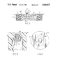
- FIG. 2 is a transverse sectional view on an enlarged scale, taken on the line 2--2 of FIG. 1, and illustrating a device embodying the invention
- FIG. 3 is a fragmentary, perspective view on an enlarged scale of the fuel hose of FIG. 1, with parts broken away for the purpose of illustration;
- FIG. 4 is a longitudinal, sectional view through the venturi section illustrated in FIGS. 2 and 3;
- FIG. 5 is a sectional view on an enlarged scale illustrating one of the three aspirator devices shown in FIGS. 2, 3, and 4, and
- FIG. 6 is a plan view of the aspirator device of FIG. 5.
- FIG. 1 there is shown a fuel dispensing installation for an automotive vehicle service station.
- the installation includes a metering console 10 in which a pump P is located.
- the outlet pipe of the pump usually extends to the front or side of the console 10, where it connects to a flexible fuel hose 11, which in turn is connected to a valved nozzle 12.
- the valved nozzle 12 may be grasped by an operator and inserted into the fill pipe of the automotive vehicle to be serviced.
- the flexible fuel hose 11 is generally formed of reinforced rubber and, in a typical installation, may be about 8 to 14 feet long.
- the fuel hose 11 is adapted to be moved from a storage position to an extended position along with the valved nozzle 12 so that the hose and nozzle can be extended to a variety of positions for connection to the fuel tank of an automotive vehicle located within the range of extension of the nozzle 12 and hose 11.
- the flexible fuel hose 11 includes a flexible inner fuel tube 14 through which the liquid fuel is transmitted, and an outer annular sleeve 13.
- the inner surface of the outer sleeve 13 and the outer surface of the fuel tube 14 define an annular vapor return passage 15 through which fuel vapors are returned from the vehicle fuel tank to the fuel reservoir.
- the flexible fuel hose 11 usually has a looped portion in which the lowest portion 16 of the hose occurs. Accordingly, any condensation which forms in the annular vapor return passage 15, or any fuel which enters the passage 15 due to splashback from the liquid fuel being dispensed into the fuel tank, collects or pools in the low zone 16. If enough liquid fuel accumulates, it will be apparent that blockage of the vapor return passage 15 wil occur and vapor will be unable to pass back to the fuel reservoir. As a result, hydrocarbon vapors will escape to atmosphere and the purpose of the vapor recovery system will be defeated.
- the liquid fuel that accumulates at the low portion 16 of the flexible fuel hose 11 is removed by means of a cylindrical venturi block 20 which is positioned within the outer sleeve 13 at approximately the low point of the hose and in series with the inner fuel tube 14.
- the venturi block 20 has a generally tubular form that defines a venturi 21 with a throat portion 22.
- Each end 23 and 24 of the block 20 is provided with a threaded socket 25 and 26, respectively, adapted to receive a threaded end portion 27, 28 of the inner tube 14, so that the venturi 21 merely constitutes a continuation of the passage through which liquid fuel flows from the pump to the valved nozzle 12.
- venturi block 20 is ideally positioned about 36 inches upstream from the valved nozzle 12. That is typically the location of the lowest portion of the flexible fuel hose 11 during vehicle fueling operations.
- the cylindrical venturi block 20 is provided with three radial bores or seats 31, 32, 33 uniformly spaced about the circumference thereof in a plane generally intersecting the throat 22 of the venturi 21. Each of these bores or seats 31, 32, and 33 has a concentric port 35, 36, 37 that extends from the base of the seat through to the venturi throat 22. Each of the seats 31, 32, and 33 has a check valve 40 seated therein of the type generally shown in FIGS. 5 and 6, and a filter 34.
- the valves 40 are of the type generally referred to as "umbrella valves" and they include a main body 41 with open-ended valve chamber 42 formed therein and a central bore 43 extending therethrough.
- an elastomeric element 44 mounted in the central bore 43 is an elastomeric element 44 with an enlarged head portion 45 located in the chamber 42 and a stem 46 which extends through the central bore 43.
- the stem 46 has relieved side wall portions 47 and 48 that define, with the bore 43, passages extending between the outer face of the valve body and the valve chamber 42.
- the valve stem 46 is locked in place by means of an enlarged flanged portion 49.
- valve 40 The purpose of the valve 40 is to permit flow of liquid through the valve from the vapor return passage to the venturi throat 22, but to block reverse flow therethrough.
- valved nozzle 12 During a refueling operation when the valved nozzle 12 is inserted into the fill pipe of a vehicle fuel tank, the operator operates the nozzle so that flow of liquid fuel through the hose 11 and valved nozzle 12 is commenced. As the liquid fuel flows through the venturi 21, an increase in velocity occurs, accompanied by a reduction in pressure. The pressure drop thus produced serves to open the umbrella valves 40 and draw into the flow any liquid fuel that has accumulated in the low portion 16 of the vapor return passage.
- the venturi block 20 is generally formed of anodized aluminum so as to be unaffected by the contaminants that would otherwise corrode the material.
- the umbrella valves 40 are generally formed of a plastic material that can be inserted in the bores or seats formed in the venturi block 20. While the device shown has three umbrella valves 40, it will be apparent that more valves may be used if desired, although at least two valves should be provided for best results.
Abstract
Description
Claims (19)
Priority Applications (4)
| Application Number | Priority Date | Filing Date | Title |
|---|---|---|---|
| US07/098,453 US4842027A (en) | 1985-12-02 | 1987-09-18 | Vapor passage fuel blockage removal |
| US07/330,149 US4967809A (en) | 1985-12-02 | 1989-03-29 | Vapor passage fuel blockage removal |
| US07/893,226 US5240045A (en) | 1985-12-02 | 1992-06-03 | Vapor passage fuel blockage removal |
| US08/083,358 US5333654A (en) | 1985-12-02 | 1993-06-28 | Vapor passage fuel blockage removal |
Applications Claiming Priority (2)
| Application Number | Priority Date | Filing Date | Title |
|---|---|---|---|
| US80315285A | 1985-12-02 | 1985-12-02 | |
| US07/098,453 US4842027A (en) | 1985-12-02 | 1987-09-18 | Vapor passage fuel blockage removal |
Related Parent Applications (2)
| Application Number | Title | Priority Date | Filing Date |
|---|---|---|---|
| US80315285A Division | 1985-12-02 | 1985-12-02 | |
| US07/113,372 Division US4749009A (en) | 1985-12-02 | 1987-10-23 | Vapor passage fuel blockage removal |
Related Child Applications (1)
| Application Number | Title | Priority Date | Filing Date |
|---|---|---|---|
| US07/330,149 Division US4967809A (en) | 1985-12-02 | 1989-03-29 | Vapor passage fuel blockage removal |
Publications (1)
| Publication Number | Publication Date |
|---|---|
| US4842027A true US4842027A (en) | 1989-06-27 |
Family
ID=26794756
Family Applications (2)
| Application Number | Title | Priority Date | Filing Date |
|---|---|---|---|
| US07/098,453 Expired - Lifetime US4842027A (en) | 1985-12-02 | 1987-09-18 | Vapor passage fuel blockage removal |
| US08/083,358 Expired - Fee Related US5333654A (en) | 1985-12-02 | 1993-06-28 | Vapor passage fuel blockage removal |
Family Applications After (1)
| Application Number | Title | Priority Date | Filing Date |
|---|---|---|---|
| US08/083,358 Expired - Fee Related US5333654A (en) | 1985-12-02 | 1993-06-28 | Vapor passage fuel blockage removal |
Country Status (1)
| Country | Link |
|---|---|
| US (2) | US4842027A (en) |
Cited By (26)
| Publication number | Priority date | Publication date | Assignee | Title |
|---|---|---|---|---|
| US4967809A (en) * | 1985-12-02 | 1990-11-06 | Tokheim Corporation | Vapor passage fuel blockage removal |
| US5035271A (en) * | 1990-04-02 | 1991-07-30 | Catlow, Inc. | Vapor recovery fuel dispensing nozzle |
| US5040576A (en) * | 1985-12-02 | 1991-08-20 | Tokheim Corporation | Vapor passage fuel blockage removal |
| US5042537A (en) * | 1987-09-18 | 1991-08-27 | Dayco Products, Inc. | Hose assembly and method of making the same |
| US5082027A (en) * | 1989-10-13 | 1992-01-21 | The Goodyear Tire & Rubber Company | Hose rotation restrainer |
| US5088528A (en) * | 1987-09-18 | 1992-02-18 | Dayco Products, Inc. | Hose assembly and method of making the same |
| US5129433A (en) * | 1985-12-02 | 1992-07-14 | Tokheim Corporation | Vapor passage fuel blockage removal |
| US5148840A (en) * | 1987-09-18 | 1992-09-22 | Dayco Products, Inc. | Hose assembly having a venturi section wtih a slide member therein and method of making the hose assembly |
| US5203384A (en) * | 1990-08-15 | 1993-04-20 | Dresser Industries, Inc. | Combination casting for a blending dispenser |
| US5240045A (en) * | 1985-12-02 | 1993-08-31 | Tokheim Corporation | Vapor passage fuel blockage removal |
| US5255723A (en) * | 1990-04-02 | 1993-10-26 | Catlow, Inc. | Vapor recovery fuel dispensing nozzle |
| US5305806A (en) * | 1992-10-16 | 1994-04-26 | Dayco Products, Inc. | Fuel dispensing system, parts therefor and methods of making the same |
| US5333654A (en) * | 1985-12-02 | 1994-08-02 | Tokheim Corporation | Vapor passage fuel blockage removal |
| US5762104A (en) * | 1995-10-10 | 1998-06-09 | Fe Petro Inc. | Liquid pumping system with pressure relief mechanism |
| USRE37114E1 (en) | 1993-11-01 | 2001-03-27 | Advanced Polymer Technology, Inc. | Secondary containment flexible underground piping system |
| US6338369B1 (en) | 1998-11-09 | 2002-01-15 | Marconi Commerce Systems Inc. | Hydrocarbon vapor sensing |
| US6347649B1 (en) | 2000-11-16 | 2002-02-19 | Marconi Commerce Systems Inc. | Pressure sensor for a vapor recovery system |
| US6357493B1 (en) | 2000-10-23 | 2002-03-19 | Marconi Commerce Systems Inc. | Vapor recovery system for a fuel dispenser |
| US6622757B2 (en) | 1999-11-30 | 2003-09-23 | Veeder-Root Company | Fueling system vapor recovery and containment performance monitor and method of operation thereof |
| US20030230352A1 (en) * | 2002-03-05 | 2003-12-18 | Hart Robert P. | Apparatus and method to control excess pressure in fuel storage containment system at fuel dispensing facilities |
| US20040069372A1 (en) * | 1999-11-30 | 2004-04-15 | Hart Robert P. | Fueling system vapor recovery and containment leak detection system and method |
| US20070267088A1 (en) * | 2006-05-04 | 2007-11-22 | Veeder-Root Company | System and method for automatically adjusting an ORVR compatible stage II vapor recovery system to maintain a desired air-to-liquid (A/L) ratio |
| US20090293592A1 (en) * | 2008-05-28 | 2009-12-03 | Franklin Fueling Systems, Inc. | Method and apparatus for monitoring for leaks in a stage ii fuel vapor recovery system |
| US20100288019A1 (en) * | 2009-05-18 | 2010-11-18 | Franklin Fueling Systems Inc. | Method and apparatus for detecting a leak in a fuel delivery system |
| US8448675B2 (en) | 2008-05-28 | 2013-05-28 | Franklin Fueling Systems, Inc. | Method and apparatus for monitoring for a restriction in a stage II fuel vapor recovery system |
| US9126820B2 (en) | 2013-02-12 | 2015-09-08 | Opw Fueling Components Inc. | Dispensing nozzle with fluid recapture |
Families Citing this family (4)
| Publication number | Priority date | Publication date | Assignee | Title |
|---|---|---|---|---|
| US7081095B2 (en) * | 2001-05-17 | 2006-07-25 | Lynn Lawrence A | Centralized hospital monitoring system for automatically detecting upper airway instability and for preventing and aborting adverse drug reactions |
| US6923221B2 (en) * | 2003-12-04 | 2005-08-02 | Gilbarco Inc. | Vapor recovery system with ORVR compensation |
| US7240739B2 (en) * | 2004-08-04 | 2007-07-10 | Schlumberger Technology Corporation | Well fluid control |
| US7921908B2 (en) * | 2008-09-18 | 2011-04-12 | Baker Hughes Incorporated | Gas restrictor for horizontally oriented pump |
Citations (37)
| Publication number | Priority date | Publication date | Assignee | Title |
|---|---|---|---|---|
| US2307085A (en) * | 1939-01-16 | 1943-01-05 | Richard R Trexler | Liquid dispensing apparatus |
| US2354695A (en) * | 1941-08-27 | 1944-08-01 | Mcglashan Alexander | Injector apparatus for the recovery of spilled beer and like beverages |
| FR915131A (en) * | 1944-06-24 | 1946-10-28 | Machf Gebr Stork & Co N V | Improvements to hydrophoric systems |
| US2540064A (en) * | 1947-12-04 | 1951-01-30 | Dishmaster Corp | Water and detergent mixer |
| US2621908A (en) * | 1946-10-12 | 1952-12-16 | Young | Liquid dispensing installations |
| US2785546A (en) * | 1954-01-07 | 1957-03-19 | Dole Valve Co | Refrigerator dispenser for concentrates |
| US2969748A (en) * | 1959-02-12 | 1961-01-31 | F E Myers & Bro Co | Ejector |
| US3338173A (en) * | 1965-07-21 | 1967-08-29 | Jr Rudolph M Gunzel | Variable fluid proportioner |
| US3850208A (en) * | 1972-03-03 | 1974-11-26 | C Hamilton | Positive displacement vapor control apparatus for fluid transfer |
| US3863687A (en) * | 1972-05-04 | 1975-02-04 | Phillips Petroleum Co | Return of vapor condensate formed in dispensing vaporous liquid |
| US3891124A (en) * | 1974-08-16 | 1975-06-24 | Emerson Electric Co | Means for storing and dispensing heated liquid with expansion chamber module and system therefor |
| US3905405A (en) * | 1973-09-25 | 1975-09-16 | Weil Mclain Company Inc | Gasoline dispensing and vapor recovery system |
| US3913633A (en) * | 1974-10-21 | 1975-10-21 | Weil Mclain Company Inc | Liquid dispensing and vapor recovery system |
| US3915206A (en) * | 1973-10-12 | 1975-10-28 | Weil Mclain Company Inc | Gasoline dispensing and vapor recovery system |
| US3952781A (en) * | 1975-01-27 | 1976-04-27 | Weil-Mclain Company, Inc. | Liquid dispensing and vapor recovery system and a vapor flow control unit used therein |
| US3981335A (en) * | 1975-03-31 | 1976-09-21 | Weil-Mclain Co., Inc. | Liquid dispensing and vapor recovery system utilizing an injector and a valve for permitting operation of leak detecting apparatus |
| US3981334A (en) * | 1975-04-04 | 1976-09-21 | Weil-Mclain Co., Inc. | Liquid dispensing and vapor recovery system utilizing an injector and an improved vapor flow control unit |
| US4009739A (en) * | 1975-09-02 | 1977-03-01 | Weatherford Danny J | Gasoline and vapor return hose system for delivery truck |
| US4033706A (en) * | 1975-08-06 | 1977-07-05 | Sundstrand Corporation | Fluid delivery system with a jet pump booster and means to maintain a constant rate of flow through the jet nozzle |
| US4057086A (en) * | 1975-02-27 | 1977-11-08 | Healy James W | Vapor control |
| US4057085A (en) * | 1975-08-20 | 1977-11-08 | International Telephone And Telegraph Corporation | Vapor recovery system |
| US4068687A (en) * | 1976-07-01 | 1978-01-17 | Long Robert A | Vapor recovery liquid dispensing apparatus |
| US4072934A (en) * | 1977-01-19 | 1978-02-07 | Wylain, Inc. | Method and apparatus for detecting a blockage in a vapor flow line |
| US4167957A (en) * | 1978-03-20 | 1979-09-18 | Atlantic Richfield Company | Hydrocarbon fuel dispensing, vapor controlling system |
| US4167958A (en) * | 1978-03-20 | 1979-09-18 | Atlantic Richfield Company | Hydrocarbon fuel dispensing, vapor controlling system |
| GB2016417A (en) * | 1978-03-20 | 1979-09-26 | Atlantic Richfield Co | Improvement in a hydrocarbon fuel dispensing, vapor controlling system |
| US4253503A (en) * | 1979-06-21 | 1981-03-03 | Texaco Inc. | Manifold fuel vapor withdrawal system |
| US4263498A (en) * | 1979-02-26 | 1981-04-21 | Hobart Corporation | Expansion chamber arrangement for water heating and dispensing device |
| US4310033A (en) * | 1979-12-10 | 1982-01-12 | The Marley-Wylain Company | Liquid dispensing and uphill vapor recovery system |
| US4336830A (en) * | 1980-04-28 | 1982-06-29 | Healy James W | Vapor recovery jet pump |
| US4395201A (en) * | 1980-02-21 | 1983-07-26 | Dan Bron | Injector pump |
| US4396356A (en) * | 1979-01-26 | 1983-08-02 | Lincoln Thompson | Aspirator and aspirating system |
| EP0155186A1 (en) * | 1984-03-15 | 1985-09-18 | Gilbarco Inc. | Venturi liquid evacuator system for maintaining clear vapor path in vapor recovery hose |
| US4566504A (en) * | 1983-09-15 | 1986-01-28 | Gilbarco Inc. | Insertion tube liquid evacuator system for vapor recovery hose |
| US4595344A (en) * | 1982-09-30 | 1986-06-17 | Briley Patrick B | Ejector and method of controlling same |
| US4687033A (en) * | 1984-03-15 | 1987-08-18 | Gilbarco, Inc. | Venturi liquid evacuator system for maintaining clear vapor path in vapor recovery hose |
| US4749009A (en) * | 1985-12-02 | 1988-06-07 | Tokheim Corporation | Vapor passage fuel blockage removal |
Family Cites Families (16)
| Publication number | Priority date | Publication date | Assignee | Title |
|---|---|---|---|---|
| US4570686A (en) * | 1983-06-24 | 1986-02-18 | Gilbarco Inc. | Apparatus for preventing blockage of vapor recovery hose by liquid fuel |
| US5040576A (en) * | 1985-12-02 | 1991-08-20 | Tokheim Corporation | Vapor passage fuel blockage removal |
| US5129433A (en) * | 1985-12-02 | 1992-07-14 | Tokheim Corporation | Vapor passage fuel blockage removal |
| US5240045A (en) * | 1985-12-02 | 1993-08-31 | Tokheim Corporation | Vapor passage fuel blockage removal |
| US4827987A (en) * | 1985-12-02 | 1989-05-09 | Tokheim Corporation | Liquid fuel blockage removal device with a venturi and bypass passages |
| US4967809A (en) * | 1985-12-02 | 1990-11-06 | Tokheim Corporation | Vapor passage fuel blockage removal |
| US4842027A (en) * | 1985-12-02 | 1989-06-27 | Tokheim Corporation | Vapor passage fuel blockage removal |
| US5005613A (en) * | 1986-09-26 | 1991-04-09 | The Goodyear Tire & Rubber Company | Light weight flexible coaxial vapor recovery hose |
| US5056569A (en) * | 1986-09-29 | 1991-10-15 | Dayco Products, Inc. | Hose assembly and method of making the same |
| US5088528A (en) * | 1987-09-18 | 1992-02-18 | Dayco Products, Inc. | Hose assembly and method of making the same |
| US4951720A (en) * | 1987-09-18 | 1990-08-28 | Dayco Products, Inc. | Hose assembly and method of making the same |
| US5148840A (en) * | 1987-09-18 | 1992-09-22 | Dayco Products, Inc. | Hose assembly having a venturi section wtih a slide member therein and method of making the hose assembly |
| US5042537A (en) * | 1987-09-18 | 1991-08-27 | Dayco Products, Inc. | Hose assembly and method of making the same |
| US5082027A (en) * | 1989-10-13 | 1992-01-21 | The Goodyear Tire & Rubber Company | Hose rotation restrainer |
| US5040577A (en) * | 1990-05-21 | 1991-08-20 | Gilbarco Inc. | Vapor recovery system for fuel dispenser |
| US5102012A (en) * | 1990-08-31 | 1992-04-07 | Dayco Products, Inc. | Fuel dispensing system having a flexible hose with a static dissipater and a fuel leak detector |
-
1987
- 1987-09-18 US US07/098,453 patent/US4842027A/en not_active Expired - Lifetime
-
1993
- 1993-06-28 US US08/083,358 patent/US5333654A/en not_active Expired - Fee Related
Patent Citations (38)
| Publication number | Priority date | Publication date | Assignee | Title |
|---|---|---|---|---|
| US2307085A (en) * | 1939-01-16 | 1943-01-05 | Richard R Trexler | Liquid dispensing apparatus |
| US2354695A (en) * | 1941-08-27 | 1944-08-01 | Mcglashan Alexander | Injector apparatus for the recovery of spilled beer and like beverages |
| FR915131A (en) * | 1944-06-24 | 1946-10-28 | Machf Gebr Stork & Co N V | Improvements to hydrophoric systems |
| US2621908A (en) * | 1946-10-12 | 1952-12-16 | Young | Liquid dispensing installations |
| US2540064A (en) * | 1947-12-04 | 1951-01-30 | Dishmaster Corp | Water and detergent mixer |
| US2785546A (en) * | 1954-01-07 | 1957-03-19 | Dole Valve Co | Refrigerator dispenser for concentrates |
| US2969748A (en) * | 1959-02-12 | 1961-01-31 | F E Myers & Bro Co | Ejector |
| US3338173A (en) * | 1965-07-21 | 1967-08-29 | Jr Rudolph M Gunzel | Variable fluid proportioner |
| US3850208A (en) * | 1972-03-03 | 1974-11-26 | C Hamilton | Positive displacement vapor control apparatus for fluid transfer |
| US3863687A (en) * | 1972-05-04 | 1975-02-04 | Phillips Petroleum Co | Return of vapor condensate formed in dispensing vaporous liquid |
| US3905405A (en) * | 1973-09-25 | 1975-09-16 | Weil Mclain Company Inc | Gasoline dispensing and vapor recovery system |
| US3915206A (en) * | 1973-10-12 | 1975-10-28 | Weil Mclain Company Inc | Gasoline dispensing and vapor recovery system |
| US3891124A (en) * | 1974-08-16 | 1975-06-24 | Emerson Electric Co | Means for storing and dispensing heated liquid with expansion chamber module and system therefor |
| US3913633A (en) * | 1974-10-21 | 1975-10-21 | Weil Mclain Company Inc | Liquid dispensing and vapor recovery system |
| US3952781A (en) * | 1975-01-27 | 1976-04-27 | Weil-Mclain Company, Inc. | Liquid dispensing and vapor recovery system and a vapor flow control unit used therein |
| US4095626A (en) * | 1975-02-27 | 1978-06-20 | Healy James W | Vapor recovery in a liquid dispensing unit |
| US4057086A (en) * | 1975-02-27 | 1977-11-08 | Healy James W | Vapor control |
| US3981335A (en) * | 1975-03-31 | 1976-09-21 | Weil-Mclain Co., Inc. | Liquid dispensing and vapor recovery system utilizing an injector and a valve for permitting operation of leak detecting apparatus |
| US3981334A (en) * | 1975-04-04 | 1976-09-21 | Weil-Mclain Co., Inc. | Liquid dispensing and vapor recovery system utilizing an injector and an improved vapor flow control unit |
| US4033706A (en) * | 1975-08-06 | 1977-07-05 | Sundstrand Corporation | Fluid delivery system with a jet pump booster and means to maintain a constant rate of flow through the jet nozzle |
| US4057085A (en) * | 1975-08-20 | 1977-11-08 | International Telephone And Telegraph Corporation | Vapor recovery system |
| US4009739A (en) * | 1975-09-02 | 1977-03-01 | Weatherford Danny J | Gasoline and vapor return hose system for delivery truck |
| US4068687A (en) * | 1976-07-01 | 1978-01-17 | Long Robert A | Vapor recovery liquid dispensing apparatus |
| US4072934A (en) * | 1977-01-19 | 1978-02-07 | Wylain, Inc. | Method and apparatus for detecting a blockage in a vapor flow line |
| US4167957A (en) * | 1978-03-20 | 1979-09-18 | Atlantic Richfield Company | Hydrocarbon fuel dispensing, vapor controlling system |
| US4167958A (en) * | 1978-03-20 | 1979-09-18 | Atlantic Richfield Company | Hydrocarbon fuel dispensing, vapor controlling system |
| GB2016417A (en) * | 1978-03-20 | 1979-09-26 | Atlantic Richfield Co | Improvement in a hydrocarbon fuel dispensing, vapor controlling system |
| US4396356A (en) * | 1979-01-26 | 1983-08-02 | Lincoln Thompson | Aspirator and aspirating system |
| US4263498A (en) * | 1979-02-26 | 1981-04-21 | Hobart Corporation | Expansion chamber arrangement for water heating and dispensing device |
| US4253503A (en) * | 1979-06-21 | 1981-03-03 | Texaco Inc. | Manifold fuel vapor withdrawal system |
| US4310033A (en) * | 1979-12-10 | 1982-01-12 | The Marley-Wylain Company | Liquid dispensing and uphill vapor recovery system |
| US4395201A (en) * | 1980-02-21 | 1983-07-26 | Dan Bron | Injector pump |
| US4336830A (en) * | 1980-04-28 | 1982-06-29 | Healy James W | Vapor recovery jet pump |
| US4595344A (en) * | 1982-09-30 | 1986-06-17 | Briley Patrick B | Ejector and method of controlling same |
| US4566504A (en) * | 1983-09-15 | 1986-01-28 | Gilbarco Inc. | Insertion tube liquid evacuator system for vapor recovery hose |
| EP0155186A1 (en) * | 1984-03-15 | 1985-09-18 | Gilbarco Inc. | Venturi liquid evacuator system for maintaining clear vapor path in vapor recovery hose |
| US4687033A (en) * | 1984-03-15 | 1987-08-18 | Gilbarco, Inc. | Venturi liquid evacuator system for maintaining clear vapor path in vapor recovery hose |
| US4749009A (en) * | 1985-12-02 | 1988-06-07 | Tokheim Corporation | Vapor passage fuel blockage removal |
Non-Patent Citations (1)
| Title |
|---|
| Gilbarco Installation Manual. * |
Cited By (54)
| Publication number | Priority date | Publication date | Assignee | Title |
|---|---|---|---|---|
| US5240045A (en) * | 1985-12-02 | 1993-08-31 | Tokheim Corporation | Vapor passage fuel blockage removal |
| US5333654A (en) * | 1985-12-02 | 1994-08-02 | Tokheim Corporation | Vapor passage fuel blockage removal |
| US5040576A (en) * | 1985-12-02 | 1991-08-20 | Tokheim Corporation | Vapor passage fuel blockage removal |
| US4967809A (en) * | 1985-12-02 | 1990-11-06 | Tokheim Corporation | Vapor passage fuel blockage removal |
| US5129433A (en) * | 1985-12-02 | 1992-07-14 | Tokheim Corporation | Vapor passage fuel blockage removal |
| US5042537A (en) * | 1987-09-18 | 1991-08-27 | Dayco Products, Inc. | Hose assembly and method of making the same |
| US5088528A (en) * | 1987-09-18 | 1992-02-18 | Dayco Products, Inc. | Hose assembly and method of making the same |
| US5148840A (en) * | 1987-09-18 | 1992-09-22 | Dayco Products, Inc. | Hose assembly having a venturi section wtih a slide member therein and method of making the hose assembly |
| US5082027A (en) * | 1989-10-13 | 1992-01-21 | The Goodyear Tire & Rubber Company | Hose rotation restrainer |
| US5255723A (en) * | 1990-04-02 | 1993-10-26 | Catlow, Inc. | Vapor recovery fuel dispensing nozzle |
| US5035271A (en) * | 1990-04-02 | 1991-07-30 | Catlow, Inc. | Vapor recovery fuel dispensing nozzle |
| US5203384A (en) * | 1990-08-15 | 1993-04-20 | Dresser Industries, Inc. | Combination casting for a blending dispenser |
| US5305806A (en) * | 1992-10-16 | 1994-04-26 | Dayco Products, Inc. | Fuel dispensing system, parts therefor and methods of making the same |
| US5361810A (en) * | 1992-10-16 | 1994-11-08 | Dayco Products, Inc. | Fuel dispensing system, parts therefor and methods of making the same |
| US5456296A (en) * | 1992-10-16 | 1995-10-10 | Dayco Products, Inc. | Fuel dispensing system, parts therefor and methods of making the same |
| USRE37114E1 (en) | 1993-11-01 | 2001-03-27 | Advanced Polymer Technology, Inc. | Secondary containment flexible underground piping system |
| US5762104A (en) * | 1995-10-10 | 1998-06-09 | Fe Petro Inc. | Liquid pumping system with pressure relief mechanism |
| US6338369B1 (en) | 1998-11-09 | 2002-01-15 | Marconi Commerce Systems Inc. | Hydrocarbon vapor sensing |
| US6802344B2 (en) | 1999-11-30 | 2004-10-12 | Veeder-Root Company | Fueling system vapor recovery and containment performance monitor and method of operation thereof |
| US6968868B2 (en) | 1999-11-30 | 2005-11-29 | Veeder-Root Company | Fueling system vapor recovery and containment performance monitor and method of operation thereof |
| US7975528B2 (en) | 1999-11-30 | 2011-07-12 | Veeder-Root Company | Fueling system vapor recovery and containment performance monitor and method of operation thereof |
| US6622757B2 (en) | 1999-11-30 | 2003-09-23 | Veeder-Root Company | Fueling system vapor recovery and containment performance monitor and method of operation thereof |
| US20030192617A1 (en) * | 1999-11-30 | 2003-10-16 | Hart Robert P. | Fueling system vapor recovery and containment performance monitor and method of operation thereof |
| US7849728B2 (en) | 1999-11-30 | 2010-12-14 | Veeder-Root Company | Fueling system vapor recovery and containment performance monitor and method of operation thereof |
| US20040069372A1 (en) * | 1999-11-30 | 2004-04-15 | Hart Robert P. | Fueling system vapor recovery and containment leak detection system and method |
| US20040154692A1 (en) * | 1999-11-30 | 2004-08-12 | Hart Robert P. | Fueling system vapor recovery and containment performance monitor and method of operation thereof |
| US8893542B2 (en) | 1999-11-30 | 2014-11-25 | Veeder-Root Company | Fueling system vapor recovery and containment performance monitor and method of operation thereof |
| US20100139371A1 (en) * | 1999-11-30 | 2010-06-10 | Veeder-Root Company | Fueling system vapor recovery and containment performance monitor and method of operation thereof |
| US6880585B2 (en) | 1999-11-30 | 2005-04-19 | Veeder-Root Company | Fueling system vapor recovery and containment performance monitor and method of operation thereof |
| US6901786B2 (en) | 1999-11-30 | 2005-06-07 | Veeder-Root Company | Fueling system vapor recovery and containment leak detection system and method |
| US6964283B2 (en) | 1999-11-30 | 2005-11-15 | Veeder-Root Company | Fueling system vapor recovery and containment performance monitor and method of operation thereof |
| US8327689B2 (en) | 1999-11-30 | 2012-12-11 | Veeder-Root Company | Fueling system vapor recovery and containment performance monitor and method of operation thereof |
| US7275417B2 (en) | 1999-11-30 | 2007-10-02 | Veeder-Root Company | Fueling system vapor recovery and containment performance monitor and method of operation thereof |
| US20100132436A1 (en) * | 1999-11-30 | 2010-06-03 | Veeder-Root Company | Fueling system vapor recovery and containment performance monitor and method of operation thereof |
| US9759631B2 (en) | 1999-11-30 | 2017-09-12 | Veeder-Root Company | Fueling system vapor recovery and containment performance monitor and method of operation thereof |
| US6357493B1 (en) | 2000-10-23 | 2002-03-19 | Marconi Commerce Systems Inc. | Vapor recovery system for a fuel dispenser |
| US6347649B1 (en) | 2000-11-16 | 2002-02-19 | Marconi Commerce Systems Inc. | Pressure sensor for a vapor recovery system |
| US6532999B2 (en) | 2000-11-16 | 2003-03-18 | Gilbarco Inc. | Pressure sensor for a vapor recovery system |
| US6840292B2 (en) | 2002-03-05 | 2005-01-11 | Veeder-Root Company | Apparatus and method to control excess pressure in fuel storage containment system at fuel dispensing facilities |
| US20030230352A1 (en) * | 2002-03-05 | 2003-12-18 | Hart Robert P. | Apparatus and method to control excess pressure in fuel storage containment system at fuel dispensing facilities |
| US20070267088A1 (en) * | 2006-05-04 | 2007-11-22 | Veeder-Root Company | System and method for automatically adjusting an ORVR compatible stage II vapor recovery system to maintain a desired air-to-liquid (A/L) ratio |
| US7909069B2 (en) | 2006-05-04 | 2011-03-22 | Veeder-Root Company | System and method for automatically adjusting an ORVR compatible stage II vapor recovery system to maintain a desired air-to-liquid (A/L) ratio |
| US20110220240A1 (en) * | 2006-05-04 | 2011-09-15 | Veeder-Root Company | System and method for automatically adjusting an orvr compatible stage ii vapor recovery system to maintain a desired air-to-liquid (a/l) ratio |
| US8573262B2 (en) | 2006-05-04 | 2013-11-05 | Veeder-Root Company | System and method for automatically adjusting an ORVR compatible stage II vapor recovery system to maintain a desired air-to-liquid (A/L) ratio |
| US20090293847A1 (en) * | 2008-05-28 | 2009-12-03 | Franklin Fueling Systems, Inc. | Method and apparatus for monitoring for a restriction in a stage ii fuel vapor recovery system |
| US8402817B2 (en) | 2008-05-28 | 2013-03-26 | Franklin Fueling Systems, Inc. | Method and apparatus for monitoring for leaks in a stage II fuel vapor recovery system |
| US8448675B2 (en) | 2008-05-28 | 2013-05-28 | Franklin Fueling Systems, Inc. | Method and apparatus for monitoring for a restriction in a stage II fuel vapor recovery system |
| US8191585B2 (en) | 2008-05-28 | 2012-06-05 | Franklin Fueling Systems, Inc. | Method and apparatus for monitoring for a restriction in a stage II fuel vapor recovery system |
| US9108837B2 (en) | 2008-05-28 | 2015-08-18 | Franklin Fueling Systems, Inc. | Method and apparatus for monitoring for a restriction in a stage II fuel vapor recovery system |
| US20090293592A1 (en) * | 2008-05-28 | 2009-12-03 | Franklin Fueling Systems, Inc. | Method and apparatus for monitoring for leaks in a stage ii fuel vapor recovery system |
| US8677805B2 (en) | 2009-05-18 | 2014-03-25 | Franklin Fueling Systems, Inc. | Method and apparatus for detecting a leak in a fuel delivery system |
| US20100288019A1 (en) * | 2009-05-18 | 2010-11-18 | Franklin Fueling Systems Inc. | Method and apparatus for detecting a leak in a fuel delivery system |
| US10337947B2 (en) | 2009-05-18 | 2019-07-02 | Franklin Fueling Systems, Inc. | Method for detecting a leak in a fuel delivery system |
| US9126820B2 (en) | 2013-02-12 | 2015-09-08 | Opw Fueling Components Inc. | Dispensing nozzle with fluid recapture |
Also Published As
| Publication number | Publication date |
|---|---|
| US5333654A (en) | 1994-08-02 |
Similar Documents
| Publication | Publication Date | Title |
|---|---|---|
| US4842027A (en) | Vapor passage fuel blockage removal | |
| US4749009A (en) | Vapor passage fuel blockage removal | |
| US4967809A (en) | Vapor passage fuel blockage removal | |
| US4827987A (en) | Liquid fuel blockage removal device with a venturi and bypass passages | |
| US5040576A (en) | Vapor passage fuel blockage removal | |
| US5129433A (en) | Vapor passage fuel blockage removal | |
| US5240045A (en) | Vapor passage fuel blockage removal | |
| EP0326842B1 (en) | Fuel dispensing systems | |
| US4687033A (en) | Venturi liquid evacuator system for maintaining clear vapor path in vapor recovery hose | |
| US4566504A (en) | Insertion tube liquid evacuator system for vapor recovery hose | |
| US4260000A (en) | Fuel dispensing system with controlled vapor withdrawal | |
| US5122264A (en) | Liquid fuel dispensing system including a filtration vessel within a sump | |
| US4253503A (en) | Manifold fuel vapor withdrawal system | |
| US5713401A (en) | Fuel dispensing and vapor recovery nozzle | |
| US4256151A (en) | System for dispensing a volatile fuel | |
| US5913336A (en) | Gasoline dispensing hose | |
| US5385178A (en) | Self-contained fuel filler system | |
| US4252161A (en) | Support for gasoline pump | |
| US5636667A (en) | Conversion of fuel dispensers to provide for vacuum assisted vapor recovery | |
| US6805173B2 (en) | Vapor space pressure control system for underground gasoline storage tank | |
| CA1290731C (en) | Vapor passage fuel blockage removal | |
| US5520228A (en) | Fuel extraction coupling for nozzle | |
| EP0598008B1 (en) | Vapor recovery system and pump | |
| US5622212A (en) | Fuel dispensing system, parts therefor and methods of making the same | |
| US5048577A (en) | Fuel dispensing vapor eliminating valve |
Legal Events
| Date | Code | Title | Description |
|---|---|---|---|
| AS | Assignment |
Owner name: TOKHEIM CORPORATION, FORT WAYNE, INDIANA, A CORP. Free format text: ASSIGNMENT OF ASSIGNORS INTEREST.;ASSIGNOR:FAETH, WARREN P.;REEL/FRAME:004804/0159 Effective date: 19870918 Owner name: TOKHEIM CORPORATION, FORT WAYNE, INDIANA, A CORP. Free format text: ASSIGNMENT OF ASSIGNORS INTEREST;ASSIGNOR:FAETH, WARREN P.;REEL/FRAME:004804/0159 Effective date: 19870918 |
|
| STCF | Information on status: patent grant |
Free format text: PATENTED CASE |
|
| FEPP | Fee payment procedure |
Free format text: PAYOR NUMBER ASSIGNED (ORIGINAL EVENT CODE: ASPN); ENTITY STATUS OF PATENT OWNER: LARGE ENTITY |
|
| AS | Assignment |
Owner name: NBD BANK, N.A. Free format text: SECURITY INTEREST;ASSIGNORS:TOKHEIM CORPORATION, A CORP. OF IN;ENVIROTRONIC CORPORATION, A CORP. OF IN;TOKHEIM INVESTMENT CORP., A CORP. OF TX;AND OTHERS;REEL/FRAME:006167/0397 Effective date: 19920529 |
|
| FPAY | Fee payment |
Year of fee payment: 4 |
|
| AS | Assignment |
Owner name: TOKHEIM CORPORATION, INDIANA Free format text: RELEASE AND REASSIGNMENT;ASSIGNOR:NBD BANK, N.A.;REEL/FRAME:008178/0907 Effective date: 19960906 |
|
| AS | Assignment |
Owner name: NBD BANK, N.A., INDIANA Free format text: SECURITY INTEREST;ASSIGNORS:TOKHEIM CORPORATION;TOKHEIM AUTOMATION CORPORATION;ENVIROTONIC SYSTEMS, INC.;AND OTHERS;REEL/FRAME:008231/0343 Effective date: 19960906 |
|
| REMI | Maintenance fee reminder mailed | ||
| FPAY | Fee payment |
Year of fee payment: 8 |
|
| SULP | Surcharge for late payment | ||
| AS | Assignment |
Owner name: NBD BANK, N.A., INDIANA Free format text: SECURITY INTEREST;ASSIGNORS:TOKHEIM CORPORATION;TOKHEIM AUTOMATION CORPORATION;ENVIROTRONIC SYSTEM;AND OTHERS;REEL/FRAME:009490/0228 Effective date: 19980930 |
|
| AS | Assignment |
Owner name: ABN AMBO BANK N.V., ILLINOIS Free format text: TRANSFER OF SECURITY INTEREST RECORDED 10/18/96;ASSIGNOR:NBD BANK, N.A.;REEL/FRAME:010618/0164 Effective date: 19991222 Owner name: ABN AMBO BANK N.V., ILLINOIS Free format text: TRANSFER OF SECURITY INTEREST RECORDED 10/7/98;ASSIGNOR:NBD BANK, N.A.;REEL/FRAME:010676/0557 Effective date: 19991222 |
|
| FPAY | Fee payment |
Year of fee payment: 12 |
|
| AS | Assignment |
Owner name: ABN AMRO BANK N.V., ILLINOIS Free format text: SECURITY AGREEMENT;ASSIGNOR:TOKHEIM CORPORTION;REEL/FRAME:012014/0756 Effective date: 20001020 |
|
| AS | Assignment |
Owner name: TOKHEIM HOLDING, B.V., NETHERLANDS Free format text: ASSIGNMENT OF ASSIGNORS INTEREST;ASSIGNOR:TOKHEIM CORPORATION;REEL/FRAME:015908/0280 Effective date: 20050418 |