US4829732A - Anchor socket jig assembly - Google Patents
Anchor socket jig assembly Download PDFInfo
- Publication number
- US4829732A US4829732A US06/848,525 US84852586A US4829732A US 4829732 A US4829732 A US 4829732A US 84852586 A US84852586 A US 84852586A US 4829732 A US4829732 A US 4829732A
- Authority
- US
- United States
- Prior art keywords
- socket
- assembly
- opening
- rail
- feet
- Prior art date
- Legal status (The legal status is an assumption and is not a legal conclusion. Google has not performed a legal analysis and makes no representation as to the accuracy of the status listed.)
- Expired - Lifetime
Links
- 239000004033 plastic Substances 0.000 claims abstract description 10
- 229920003023 plastic Polymers 0.000 claims abstract description 10
- 239000000203 mixture Substances 0.000 claims abstract description 5
- 239000002184 metal Substances 0.000 claims description 3
- 230000013011 mating Effects 0.000 abstract description 2
- 210000002683 foot Anatomy 0.000 description 24
- 210000003423 ankle Anatomy 0.000 description 5
- 239000000463 material Substances 0.000 description 5
- 210000003414 extremity Anatomy 0.000 description 4
- 230000009182 swimming Effects 0.000 description 4
- 238000003466 welding Methods 0.000 description 3
- 238000004873 anchoring Methods 0.000 description 2
- 238000009412 basement excavation Methods 0.000 description 2
- 239000004417 polycarbonate Substances 0.000 description 2
- 229920000515 polycarbonate Polymers 0.000 description 2
- -1 polyethylene Polymers 0.000 description 2
- XLYOFNOQVPJJNP-UHFFFAOYSA-N water Substances O XLYOFNOQVPJJNP-UHFFFAOYSA-N 0.000 description 2
- 239000004677 Nylon Substances 0.000 description 1
- 239000004698 Polyethylene Substances 0.000 description 1
- 239000004743 Polypropylene Substances 0.000 description 1
- 230000000712 assembly Effects 0.000 description 1
- 238000000429 assembly Methods 0.000 description 1
- 230000000694 effects Effects 0.000 description 1
- 238000009434 installation Methods 0.000 description 1
- 229920001778 nylon Polymers 0.000 description 1
- 229920000573 polyethylene Polymers 0.000 description 1
- 229920001155 polypropylene Polymers 0.000 description 1
- 239000004800 polyvinyl chloride Substances 0.000 description 1
- 229920000915 polyvinyl chloride Polymers 0.000 description 1
- 230000003014 reinforcing effect Effects 0.000 description 1
- 230000000717 retained effect Effects 0.000 description 1
- 238000000926 separation method Methods 0.000 description 1
Images

Classifications
-
- E—FIXED CONSTRUCTIONS
- E04—BUILDING
- E04H—BUILDINGS OR LIKE STRUCTURES FOR PARTICULAR PURPOSES; SWIMMING OR SPLASH BATHS OR POOLS; MASTS; FENCING; TENTS OR CANOPIES, IN GENERAL
- E04H4/00—Swimming or splash baths or pools
- E04H4/14—Parts, details or accessories not otherwise provided for
- E04H4/144—Means for facilitating access, e.g. step units or slides
Definitions
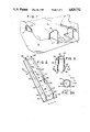
- FIG. 1 is a fragmentary perspective view illustrating one utility of the invention in which the ends of hand rails for swimming pool steps and ladder are embedded in the concrete deck surrounding a swimming pool; the jig of the invention embedded in the concrete and outlined by the broken line in the concrete deck shown in FIG. 1 provides the securing means for the rails which are removably secured in the sockets of the jig.
- FIG. 2 is a perspective view of the longitudinal base member of the jig assembly of the invention.
- FIG. 3 is a perspective view of the socket member used with the base of FIG. 2 or 2A in the assembly of the invention.
- FIG. 4 is a perspective view of the socket member with the feet thereof secured in the openings at the bottom of the base member to provide the jig assembly of the invention.
- the assembly of the invention comprises a rail member in which cooperating pairs of apertures are formed at the base of the rails in which the socket member feet are introduced and securely held.
- a fragmentary portion of a swimming pool 11 having a surrounding deck portion 12 and conventional ladder 14 and steps 15 with railing 16 is illustrated.
- the jig assembly of the invention is employed at any location where it is desired to attach an implement on a concrete structure and to provide a secure anchor (which is embedded in concrete) for the implement.
- the position of jig assembly of the invention which is employed as such anchoring means is indicated by broken line "J" at the base of the rail members 14 and 16 in FIG. 1.
- the base member 20 of the jig assembly of the invention comprises a longitudinal member having a base portion 21 and a pair of spaced rails 24 and 25 thereon defining a central base portion 26.
- the socket member 32 hereinafter described in greater detail, is positioned on base portion 26 between the rails 24 and 25.
- the base member 20 may optionally be provided also with outboard segments 22 and 23 when desired, as for example, to provide supplementary securing means for the jig assembly when placed on location, prior to pouring concrete, and to avoid dislocation of the jig assembly by workmen at the worksite or by the weight of concrete on the jig assembly.
- the base member may be formed without the outboard sections 22 and 23 in which case it comprises a longitudinal member which is generally U-shaped in cross-section formed by base 26 and side rails 24 and 25 as in FIG. 2A.
- the base member is provided with a series of socketfoot size locating openings 27 of a size which fit a foot of the socket member, three of which 35, 36 and 37 are shown in FIG. 3 and a series of slots 28 opposite to, and generally cooperating with, the openings 27 to hold opposite feet of the socket member 32.
- the openings 27 and slots 28 are spaced at suitable incremental distances at the base of the rail portions 24 and 25 to accommodate implements having distances of various sizes such as the spaced ladder rails of FIG. 1. While the openings 27 may be formed all on one rail and the slots 28 all on the other rail, as in FIG. 2A, it is preferred that openings 27 and slots 28 both be alternated on each of the rails 24 and 25.
- the base member 20 is formed from suitable plastic composition such as polyvinyl chloride or other plastic material such as polyethylene, polypropylene, polycarbonate, nylon, and the like, which is sufficiently rigid and has suitable impact resistance.
- suitable plastic composition such as polyvinyl chloride or other plastic material such as polyethylene, polypropylene, polycarbonate, nylon, and the like, which is sufficiently rigid and has suitable impact resistance.
- the thickness of the plastic material for the member 24, particularly that of the rail portions 24 and 25 is sufficiently substantial, e.g. of the order of 1/8" thickness or greater, to prevent significant distortion and provide an adequate locking hold on the socket member 32 secured therein.
- the socket member 32 is formed of a suitable material preferably a cast metal, but may comprise also a suitable plastic material of appropriate thickness and rigidity such as polycarbonate.
- the locking feet 34, 35, 36 and 37 formed at the base of the socket member 32 as shown by reference to FIG. 3A extend from the cylindrical body so that the distance D-2 between the extremities of adjacent feet does not exceed the distance D-1 between the rail member 24 and 25 of the base member 20.
- the feet 34, 35, 36 and 37 are formed so as to have a tapered or "ankle" transitional part 40 such that when the socket member 32 is positioned and bottomed in the space 26 between the rails 24 and 25, i.e. with the feet 34, 35, 36 and 37 of the socket 32 between the rails 24 and 25 of the member 20, with one of said feet in an opening 27, and the socket member 32 is rotated 90 degrees, the socket 32 is securely locked in the base member 20.
- the slot 28 may be provided with a protrusion 29 at the top of slot 28 which the ankle portion 40 overrides as the socket 32 is being rotated in place, to preclude the possibility of inadvertent dislocation (i.e. reverse rotation) of socket member 32 from a secure lock in base 20.
- an opening 44 is provided at the bottom of the socket member 32.
- a corresponding opening 45, in alignment with the socket member drainage opening 44 is provided in the portion 26 of the base member 20 to allow free passage therethrough of water that may tend to accumulate in the socket member 32.
- the base member 20 may also be provided with reinforcing rod (rerod) securing openings 46 at suitably spaced locations in the central portion 26 of base member 20.
- FIG. 4 The relationship of the socket member 32 locked on the base member 20 is best illustrated in FIG. 4.
- the foot 37 enters the opening 27 and foot 35, because of the tolerance permitted by the longitudinal slot 28, traverses the slot 28 from unlocked to locked position, left to right, as shown in FIG. 4 as the socket is rotated in the direction of the arrow.
- the assembled jig comprising the base member 20 and socket member 32, is illustrated in position in an excavation, being retained against movement by suitable securing braces 41 and 42, preparatory to pouring of concrete and embedding the assembly such that the top of the socket member 32 is essentially flush with the contiguous concrete surface.
- an implement with a securing portion such as a ladder runner, of a dimension which conforms to the inside of socket 32 is introduced into the opening 33 and is secured in place by rotating the screw 39 in the socket locking adapter 38 raising the locking element L which binds or seizes the portion of the securing element which has been inserted into the socket opening 33.
Abstract
Description
Claims (10)
Priority Applications (2)
| Application Number | Priority Date | Filing Date | Title |
|---|---|---|---|
| US06/848,525 US4829732A (en) | 1986-04-07 | 1986-04-07 | Anchor socket jig assembly |
| CA000527068A CA1284726C (en) | 1986-04-07 | 1987-01-09 | Anchor socket jig assembly |
Applications Claiming Priority (1)
| Application Number | Priority Date | Filing Date | Title |
|---|---|---|---|
| US06/848,525 US4829732A (en) | 1986-04-07 | 1986-04-07 | Anchor socket jig assembly |
Publications (1)
| Publication Number | Publication Date |
|---|---|
| US4829732A true US4829732A (en) | 1989-05-16 |
Family
ID=25303530
Family Applications (1)
| Application Number | Title | Priority Date | Filing Date |
|---|---|---|---|
| US06/848,525 Expired - Lifetime US4829732A (en) | 1986-04-07 | 1986-04-07 | Anchor socket jig assembly |
Country Status (2)
| Country | Link |
|---|---|
| US (1) | US4829732A (en) |
| CA (1) | CA1284726C (en) |
Cited By (8)
| Publication number | Priority date | Publication date | Assignee | Title |
|---|---|---|---|---|
| US5282282A (en) * | 1990-03-05 | 1994-02-01 | Shehan Billy C | Swimming pool and cover |
| US5816554A (en) * | 1996-11-18 | 1998-10-06 | Mccracken; Ronald G. | Equipment support base |
| US6324800B1 (en) | 1999-12-06 | 2001-12-04 | Portable Pipe Hangers, Inc. | Support base |
| US6585220B1 (en) * | 2000-10-11 | 2003-07-01 | Daniel T. Shemuga | Support apparatus for rollout awnings |
| US6592093B2 (en) | 2001-07-31 | 2003-07-15 | Portable Pipe Hangers, L.P. | Support base |
| US6684588B1 (en) * | 2002-05-22 | 2004-02-03 | Jesse Jones | Bonded swimming pool ladder anchor socket |
| US7437857B1 (en) | 2004-02-11 | 2008-10-21 | Spectrum Products, Llc | Compression anchor |
| US10180011B2 (en) | 2014-09-02 | 2019-01-15 | Jarrod Conway WHITE | Post support apparatus |
Citations (13)
| Publication number | Priority date | Publication date | Assignee | Title |
|---|---|---|---|---|
| US909769A (en) * | 1908-04-28 | 1909-01-12 | Omer Lestly Downing | Adjustable hanger. |
| US1281699A (en) * | 1915-01-25 | 1918-10-15 | Gen Fire Extinguisher Co | Insert for concrete structures. |
| FR504475A (en) * | 1918-10-03 | 1920-07-06 | Kendall S Haines | Improvements to the columns removable by the foot |
| US1586833A (en) * | 1924-04-03 | 1926-06-01 | Roy E Nicholson | Anchoring device for hand rails and the like |
| US1939968A (en) * | 1930-08-09 | 1933-12-19 | Jr John Frei | Flexible post |
| US2966708A (en) * | 1956-10-29 | 1961-01-03 | Joseph O Theriot | Stud anchor plate |
| US3055460A (en) * | 1958-09-11 | 1962-09-25 | Southwestern Porcelain Steel C | Building construction |
| US3065820A (en) * | 1961-04-25 | 1962-11-27 | Swimquip Inc | Swimming pool grab rail structure |
| US3894375A (en) * | 1974-01-22 | 1975-07-15 | Jr Albert W Lindberg | Pole base |
| US4008550A (en) * | 1974-09-19 | 1977-02-22 | Samuel Kaufman | Device for setting sockets for swimming pool ladders |
| DE2604850A1 (en) * | 1976-02-07 | 1977-08-11 | Beine Karlheinz | Masonry or concrete anchor bar - has rear pressed sections engaged by inserted anchor hammerhead turned through 90 degrees |
| US4059934A (en) * | 1976-09-03 | 1977-11-29 | Senoh Kabushiki Kaisha | Arrangement for fastening an upstanding post to a floorboard |
| DE3232105A1 (en) * | 1981-07-15 | 1984-03-01 | BWM Dübel- u. Montagetechnik GmbH, 7022 Leinfelden-Echterdingen | Connecting device for a curtain wall facing or suspended ceiling facing |
-
1986
- 1986-04-07 US US06/848,525 patent/US4829732A/en not_active Expired - Lifetime
-
1987
- 1987-01-09 CA CA000527068A patent/CA1284726C/en not_active Expired - Lifetime
Patent Citations (13)
| Publication number | Priority date | Publication date | Assignee | Title |
|---|---|---|---|---|
| US909769A (en) * | 1908-04-28 | 1909-01-12 | Omer Lestly Downing | Adjustable hanger. |
| US1281699A (en) * | 1915-01-25 | 1918-10-15 | Gen Fire Extinguisher Co | Insert for concrete structures. |
| FR504475A (en) * | 1918-10-03 | 1920-07-06 | Kendall S Haines | Improvements to the columns removable by the foot |
| US1586833A (en) * | 1924-04-03 | 1926-06-01 | Roy E Nicholson | Anchoring device for hand rails and the like |
| US1939968A (en) * | 1930-08-09 | 1933-12-19 | Jr John Frei | Flexible post |
| US2966708A (en) * | 1956-10-29 | 1961-01-03 | Joseph O Theriot | Stud anchor plate |
| US3055460A (en) * | 1958-09-11 | 1962-09-25 | Southwestern Porcelain Steel C | Building construction |
| US3065820A (en) * | 1961-04-25 | 1962-11-27 | Swimquip Inc | Swimming pool grab rail structure |
| US3894375A (en) * | 1974-01-22 | 1975-07-15 | Jr Albert W Lindberg | Pole base |
| US4008550A (en) * | 1974-09-19 | 1977-02-22 | Samuel Kaufman | Device for setting sockets for swimming pool ladders |
| DE2604850A1 (en) * | 1976-02-07 | 1977-08-11 | Beine Karlheinz | Masonry or concrete anchor bar - has rear pressed sections engaged by inserted anchor hammerhead turned through 90 degrees |
| US4059934A (en) * | 1976-09-03 | 1977-11-29 | Senoh Kabushiki Kaisha | Arrangement for fastening an upstanding post to a floorboard |
| DE3232105A1 (en) * | 1981-07-15 | 1984-03-01 | BWM Dübel- u. Montagetechnik GmbH, 7022 Leinfelden-Echterdingen | Connecting device for a curtain wall facing or suspended ceiling facing |
Non-Patent Citations (1)
| Title |
|---|
| Trade Brochure, Fox Pool Corporation, York, PA, Copyright 1985, p. 23. * |
Cited By (11)
| Publication number | Priority date | Publication date | Assignee | Title |
|---|---|---|---|---|
| US5282282A (en) * | 1990-03-05 | 1994-02-01 | Shehan Billy C | Swimming pool and cover |
| US5816554A (en) * | 1996-11-18 | 1998-10-06 | Mccracken; Ronald G. | Equipment support base |
| US6324800B1 (en) | 1999-12-06 | 2001-12-04 | Portable Pipe Hangers, Inc. | Support base |
| US6663070B2 (en) | 1999-12-06 | 2003-12-16 | Portable Pipe Hangers, Inc. | Support base for equipment |
| US20040084596A1 (en) * | 1999-12-06 | 2004-05-06 | Portable Pipe Hangers, Inc. | Support base for equipment |
| US6863253B2 (en) | 1999-12-06 | 2005-03-08 | Valentz Family Limited Partnership | Support base for equipment |
| US6585220B1 (en) * | 2000-10-11 | 2003-07-01 | Daniel T. Shemuga | Support apparatus for rollout awnings |
| US6592093B2 (en) | 2001-07-31 | 2003-07-15 | Portable Pipe Hangers, L.P. | Support base |
| US6684588B1 (en) * | 2002-05-22 | 2004-02-03 | Jesse Jones | Bonded swimming pool ladder anchor socket |
| US7437857B1 (en) | 2004-02-11 | 2008-10-21 | Spectrum Products, Llc | Compression anchor |
| US10180011B2 (en) | 2014-09-02 | 2019-01-15 | Jarrod Conway WHITE | Post support apparatus |
Also Published As
| Publication number | Publication date |
|---|---|
| CA1284726C (en) | 1991-06-11 |
Similar Documents
| Publication | Publication Date | Title |
|---|---|---|
| US4594157A (en) | Inlet clamp and screen | |
| US5060435A (en) | Bracket for support of vertical pole | |
| US5395184A (en) | Structure load transfer systems | |
| US4829732A (en) | Anchor socket jig assembly | |
| US5609005A (en) | Foundation connector for tilt-up concrete wall panel and method of use | |
| US3934422A (en) | Pile splicing apparatus and method | |
| CA2124813A1 (en) | Ground anchors | |
| CA1070052A (en) | Swimming pool structure and method of erecting the same | |
| US3466676A (en) | Pool structure | |
| US5496016A (en) | Fence system | |
| US3798857A (en) | Swimming pool | |
| CA2142495A1 (en) | Bracket for supporting fence posts | |
| US5611523A (en) | Fence system | |
| AU728058B2 (en) | Safety fence | |
| US20020189193A1 (en) | Barrier cable end bracket assembly | |
| US6126147A (en) | Fence post apparatus | |
| US5697600A (en) | Fence post apparatus | |
| US20030038281A1 (en) | Fencing unit with t-post engagement means and lateral bracing system using same | |
| GB2272717A (en) | Mounting poles,posts,etc.,vertically | |
| KR930002714Y1 (en) | Prefabricated fence | |
| KR200152743Y1 (en) | Angle bearing member for steel rail | |
| AU658252B2 (en) | Ground anchors | |
| CA2010740C (en) | Post beam lock connection | |
| JP3270603B2 (en) | Anchor bolt mounting method | |
| KR102626644B1 (en) | Deck guardrail system with adjustable angle |
Legal Events
| Date | Code | Title | Description |
|---|---|---|---|
| AS | Assignment |
Owner name: QUAKER PLASTIC CORPORATION, 103 SOUTH MANOR STREET Free format text: ASSIGNMENT OF ASSIGNORS INTEREST.;ASSIGNORS:DAHOWSKI, DONALD E.;CRANDALL, SCOTT E.;REEL/FRAME:004589/0490;SIGNING DATES FROM 19860728 TO 19860807 |
|
| STCF | Information on status: patent grant |
Free format text: PATENTED CASE |
|
| FPAY | Fee payment |
Year of fee payment: 4 |
|
| AS | Assignment |
Owner name: YORK BANK AND TRUST COMPANY, THE, PENNSYLVANIA Free format text: ASSIGNMENT OF ASSIGNORS INTEREST.;ASSIGNOR:QUAKER PLASTIC CORPORATION A CORP. OF PENNSYLVANIA;REEL/FRAME:006308/0701 Effective date: 19921117 |
|
| AS | Assignment |
Owner name: CONGRESS FINANCIAL CORP. (SOUTHWEST), TEXAS Free format text: SECURITY INTEREST;ASSIGNOR:QUAKER PLASTIC CORPORATION;REEL/FRAME:006893/0724 Effective date: 19931213 |
|
| AS | Assignment |
Owner name: QUAKER PLASTICS CORPORATION, PENNSYLVANIA Free format text: STATEMENT OF RELEASE OF PATENT SECURITY AGGT.;ASSIGNOR:YORK BANK AND TRUST COMPANY, THE;REEL/FRAME:007017/0558 Effective date: 19940315 |
|
| FPAY | Fee payment |
Year of fee payment: 8 |
|
| FPAY | Fee payment |
Year of fee payment: 12 |