US4827627A - Apparatus and method for controlling a drying cycle of a clothes dryer - Google Patents
Apparatus and method for controlling a drying cycle of a clothes dryer Download PDFInfo
- Publication number
- US4827627A US4827627A US07/158,496 US15849688A US4827627A US 4827627 A US4827627 A US 4827627A US 15849688 A US15849688 A US 15849688A US 4827627 A US4827627 A US 4827627A
- Authority
- US
- United States
- Prior art keywords
- burner
- temperature
- time
- dryness
- clothes
- Prior art date
- Legal status (The legal status is an assumption and is not a legal conclusion. Google has not performed a legal analysis and makes no representation as to the accuracy of the status listed.)
- Expired - Fee Related
Links
Images


Classifications
-
- D—TEXTILES; PAPER
- D06—TREATMENT OF TEXTILES OR THE LIKE; LAUNDERING; FLEXIBLE MATERIALS NOT OTHERWISE PROVIDED FOR
- D06F—LAUNDERING, DRYING, IRONING, PRESSING OR FOLDING TEXTILE ARTICLES
- D06F58/00—Domestic laundry dryers
- D06F58/32—Control of operations performed in domestic laundry dryers
- D06F58/34—Control of operations performed in domestic laundry dryers characterised by the purpose or target of the control
- D06F58/36—Control of operational steps, e.g. for optimisation or improvement of operational steps depending on the condition of the laundry
- D06F58/38—Control of operational steps, e.g. for optimisation or improvement of operational steps depending on the condition of the laundry of drying, e.g. to achieve the target humidity
-
- D—TEXTILES; PAPER
- D06—TREATMENT OF TEXTILES OR THE LIKE; LAUNDERING; FLEXIBLE MATERIALS NOT OTHERWISE PROVIDED FOR
- D06F—LAUNDERING, DRYING, IRONING, PRESSING OR FOLDING TEXTILE ARTICLES
- D06F2103/00—Parameters monitored or detected for the control of domestic laundry washing machines, washer-dryers or laundry dryers
- D06F2103/02—Characteristics of laundry or load
- D06F2103/08—Humidity
-
- D—TEXTILES; PAPER
- D06—TREATMENT OF TEXTILES OR THE LIKE; LAUNDERING; FLEXIBLE MATERIALS NOT OTHERWISE PROVIDED FOR
- D06F—LAUNDERING, DRYING, IRONING, PRESSING OR FOLDING TEXTILE ARTICLES
- D06F2103/00—Parameters monitored or detected for the control of domestic laundry washing machines, washer-dryers or laundry dryers
- D06F2103/28—Air properties
- D06F2103/32—Temperature
-
- D—TEXTILES; PAPER
- D06—TREATMENT OF TEXTILES OR THE LIKE; LAUNDERING; FLEXIBLE MATERIALS NOT OTHERWISE PROVIDED FOR
- D06F—LAUNDERING, DRYING, IRONING, PRESSING OR FOLDING TEXTILE ARTICLES
- D06F2103/00—Parameters monitored or detected for the control of domestic laundry washing machines, washer-dryers or laundry dryers
- D06F2103/38—Time, e.g. duration
-
- D—TEXTILES; PAPER
- D06—TREATMENT OF TEXTILES OR THE LIKE; LAUNDERING; FLEXIBLE MATERIALS NOT OTHERWISE PROVIDED FOR
- D06F—LAUNDERING, DRYING, IRONING, PRESSING OR FOLDING TEXTILE ARTICLES
- D06F2105/00—Systems or parameters controlled or affected by the control systems of washing machines, washer-dryers or laundry dryers
- D06F2105/28—Electric heating
-
- D—TEXTILES; PAPER
- D06—TREATMENT OF TEXTILES OR THE LIKE; LAUNDERING; FLEXIBLE MATERIALS NOT OTHERWISE PROVIDED FOR
- D06F—LAUNDERING, DRYING, IRONING, PRESSING OR FOLDING TEXTILE ARTICLES
- D06F2105/00—Systems or parameters controlled or affected by the control systems of washing machines, washer-dryers or laundry dryers
- D06F2105/62—Stopping or disabling machine operation
-
- D—TEXTILES; PAPER
- D06—TREATMENT OF TEXTILES OR THE LIKE; LAUNDERING; FLEXIBLE MATERIALS NOT OTHERWISE PROVIDED FOR
- D06F—LAUNDERING, DRYING, IRONING, PRESSING OR FOLDING TEXTILE ARTICLES
- D06F58/00—Domestic laundry dryers
- D06F58/20—General details of domestic laundry dryers
- D06F58/26—Heating arrangements, e.g. gas heating equipment
- D06F58/263—Gas heating equipment
Definitions
- the present invention relates to apparatus for drying clothes with heated air. Specifically, a controller is described which would establish a precise drying cycle to obtain a desired dryness level.
- Conventional clothes dryers comprise a tumbling chamber into which a load of wet clothing is inserted.
- the chamber includes a tumbler which is rotated to effect tumbling of the clothes.
- a stream of hot air is forced through the tumbler, which, over a given time cycle, removes the moisture contained in the clothing.
- Prior art clothes dryers set a drying cycle based upon an estimate of an appropriate drying time. Usually the operator will set a timer to a drying time which is based on human experience. At the conclusion of the drying time, the operator will check to see if the clothes are sufficiently dry. If not, a shorter timing cycle will be set, at the end of which the operator again checks the dryness of the clothing.
- Sensing the actual required time to dry a given load of wet clothing to a predetermined moisture content is made difficult by a number of factors. Among these include the size of the load being dried. It is very difficult for a human operator to estimate differences in drying time versus load sizes. Any changes in the availability of the temperature of the drying air will also affect the drying time.
- U.S. Pat. No. 4,622,759 describes a clothes dryer which computes drying time based on the rate of change of an exhaust temperature for the dryer. When the rate of change reaches a predetermined value, this is used as an indication of the dryness level, ending the drying cycle.
- U.S. Pat. No. 3,510,957 describes a dryer control system which counts the number of times a hot air heater is turned on and off to maintain a desired temperature. After a predetermined accumulated total of on and off times, the machine will enter a final drying cycle.
- the present invention is also directed to the problem of establishing an optimum drying time based on a measured dryness level of a load being dried.
- the drying temperature is established for the clothes dryer at a precision set point.
- the source of heat supplying heated air to the load of clothes being dried is continually cycled on and off to maintain the drying temperature at the set point.
- Control over the drying temperature is maintained by monitoring the temperature of the exhaust air exiting the drying chamber.
- a temperature sensor is preferably located in the exhaust port of the dryer, and gives an accurate indication of the drying temperature within the chamber.
- a microprocessor continuously monitors the temperature sensor, and an enabling signal is supplied to the burner each time the temperature sensor indicates an average temperature below the set point temperature. Each time the drying chamber temperature is determined to be above the set point, the burner is disabled, permitting the drying chamber with the load of clothing to cool down to the set point temperature.
- a real time dryness level is continuously computed during the time the burner is being cycled on and off.
- Each on and off cycle of the burner is stored in a memory by the microprocessor.
- Computations of the real time dryness level for the load of clothes is computed based on the stored on and off times for the burner. Preferably, the on and off times for several cycles of burner operation are averaged, and the difference between on and off times used to compute an effective dryness level for the load.
- This dryness level in a preferred embodiment is expressed as an equation, ##EQU1##
- Ts represents the set point temperature and a and b are thermal coefficients for a particular machine. These constants would typically lie in the range of 2-9, and 50-81, respectively.
- the computed dryness level for the clothing load may be continuously compared to a desired dryness level which could be up to 100% dryness. Once a computed dryness level is determined to be equal to the desired dryness level, the drying cycle is at an end, and the dryer may then enter a terminating phase, such as a cool down cycle, or other concluding drying cycle known in the art.
- a terminating phase such as a cool down cycle, or other concluding drying cycle known in the art.
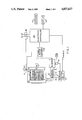
- FIG. 1 is an overall block diagram illustrating the configuration of a preferred embodiment of the invention for establishing a drying cycle.
- FIG. 2A illustrates the change in temperature over time versus the set point temperature during a drying cycle.
- FIG. 2B illustrates the on/off time for the burner used to heat the drying air during the drying cycle.
- FIG. 2C illustrates the differential between on time and off time for the burner for a drying cycle.
- FIG. 2D illustrates the level of dryness achieved over a drying cycle and the relationship between dryness between time on minus time off computations of FIG. 2C.
- FIGS. 3A and 3B comprise a detailed schematic of the apparatus for computing the dryness level as well as establishing the set point temperature.
- FIG. 4 is a block diagram of the programming steps executed by the microprocessor of FIGS. 3A and 3B to calculate dryness level.
- Dryer chamber 12 is seen to comprise a tumbler 13 having a plurality of paddles for tumbling the clothing load.
- an air distributor 11 which supplies air to the clothing chamber 12, heated by burner 16. The hot air laden with moisture exits an exhaust port 14.
- An electronic controller 35 will enable the tumbler motor control 24 at the initiation of a drying cycle.
- the tumbler motor control is, of course, known in the art, and further description is unnecessary.
- the burner control module 17 will enable solenoid 18 to supply a gas fuel to the burner 16.
- An igniter line 22 will provide an ignition source for the gas.
- a flame sensing line 21 provides feedback to the burner control circuit 17. These ignition line 22 and sensing line 21 are, of course, known in the burner control art.
- the burner control circuit 17 receives an ENABLE and DISABLE signal from the controller 35.
- a keyboard 37 and display 38 are used to interface the operator to the electronic controller 35.
- the electronic controller includes a programmable microprocessor, which can read keyboard commands from keyboard 37, as well as display various computed parameters in display 38.
- a power supply 36 supplies the operating voltage to the electronic controller 35.
- Power supply 36 is interlocked with a safety interlock 30, shown in the exhaust 14 of the dryer. In the event of a catastrophic failure and a fire condition, safety interlock 30 will interrupt the power supply 36. This standard safety feature is industry-wide and also needs no further explanation.
- a temperature sensor 32 is shown in the exhaust 14 which will give an accurate measurement of the drying temperature for the air in chamber 12.
- the electronic controller 35 through the use of the microprocessor, will continuously read out values of temperature for the drying chamber 12, and based on the temperature readings, compare them with a known set point which has been preprogrammed in the electronic controller 35.
- the relationship between the sensed temperature from sensor 32 and set point versus burner control signal is shown more particularly in FIGS. 2A and 2B.
- FIGS. 2A and 2B there is shown the operation of the burner 16, vis a vis the temperature set point and measured temperature.
- FIG. 2A illustrates how initially during a beginning drying cycle the temperature of the drying chamber 12 increases until the set point is reached, T s (° F).
- the sensor 32 which will be explained in greater detail regarding FIG. 3A, is a two terminal IC temperature transducer having plus or minus 0.5° C. calibration accuracy, monitors the drying air temperature. Once the drying air temperature as sensed by sensor 32 reaches the set point, the burner control 17 is disabled, as is illustrated in FIG. 2B.
- burner control circuit 17 enables the burner again for a period of time sufficient to sense a temperature increase to the set point temperature.
- FIGS. 2A and 2B illustrate, it is possible to maintain the drying temperature to within a 3° F. range of the desired set point. Enough BTU heat is added to the drying air to maintain drying at this desired temperature.
- the amount of heat necessary to maintain the temperature at the set point decreases. As is illustrated in FIG. 2B, as the drying time increases, the burner is enabled for a lesser amount of time.
- FIG. 2C illustrate the difference between the burner time on and time off over a typical drying cycle.
- FIG. 2D illustrates the percent of dryness of the load over the same time interval. It is clear from these two Figures that there is a relationship between ⁇ t, time on minus time off for the burner, and the dryness level of the load. Thus, by accurately monitoring ⁇ t, one can precisely estimate the percent dryness level of the clothing load.
- Q in the total heat added to the drying chamber, will equal Q out until dryness is equal to 100% (no moisture content).
- Q s will start to increase in relative proportion with respect to Q in .
- the difference ⁇ t in time on minus time off can be expressed in terms of the following relationship: ##EQU2## where ⁇ t is the time on minus time off, Ts is the set point temperature, a is a thermal coefficient determined experimentally for the given machine, and b is a second experimentally determined factor.
- the electronic controller 35 will calculate the foregoing ⁇ t and associated dryness level, based on the current provided by temperature sensor 32.
- the temperature sensor 32 may be the Analog Devices type AD-590 two terminal integrated circuit temperature transducer.
- the device is basically a current source as described in the literature of Analog Devices.
- the device is connected across terminals 38 and 39.
- Terminal 38 is connected through a 10 OHM resistor to a source of DC potential for operating the current source.
- the derived current is applied to the input of an integrated circuit 555, also made by Analog Devices, for converting the derived current into a pulse signal having a frequency proportional to the magnitude of the sensor current.
- Microprocessor 40 has a clock signal derived from the piezoelectric transducer 41 with a frequency of 3.579 megacycles.
- the 8051 will sample the signal appearing on P35 and from the sampled signal, determine the frequency, and therefore the temperature being sensed.
- the nominal frequency of the integrated circuit 555 output signal may be trimmed by setting potentiometer 42.
- the programmable microprocessor 40 is shown associated with two decoders 43, 44 and an audio transducer 45.
- a display 49 is also provided, connected to the decoders through a display drive 50 for periodically displaying a computed dryness level, or a sensed temperature under control of the system operator.
- the keyboard input is shown on terminals 52 to permit selection of the display as being either a computed dryness level or sensed temperature.
- An EEPROM 53 is provided to store the constants a and b for use in determining the dryness level from the sensed temperature, and time differential ⁇ t.
- Standard circuitry appearing on FIG. 3 includes a reset generator 54 for being certain the reset line RST is held to an appropriate logic level at the time of enablement.
- the decoders 43, 44 provide outputs for controlling the burner controller 17.
- the burner controller 17 is operated from the closure of contacts 56 which is associated with the relay 57.
- the energization of relay 57 occurs when the microprocessor 40 has determined that the temperature has fallen below the set point.
- a second relay 58 is shown which enables the tumbler motor control circuit 24 to energize the tumbler motor 15. This, of course, is analogous to the signal line entering the tumbler motor control 24 of FIG. 1, and is not part of the current invention.
- the foregoing microprocessor 40 can be programmed to continuously sense the temperature, provide the necessary control for the burner control 17, as well as compute dryness levels.
- FIG. 4 illustrates the programming scheme for the microprocessor which will implement these functions.
- Block 101 illustrates the beginning of a drying cycle.
- the tumbler motor is energized in block 102 and an ENABLE signal applied to the burner control circuit 17. Initially, the temperature will increase from ambient to the set point as shown in the early part of the temperature curve of FIG. 2A.
- the exhaust air temperature is continuously measured in step 104 when the microprocessor samples the port P35 at periodic intervals.
- the frequency of the signal appearing on port P35 will be proportional to the exhaust air temperature.
- the heat is disabled in 106. Referring again to FIG. 2A, this would comprise the first time since initialization that the burner is turned off, delivering no additional heat. This will also begin the reset of the timer counters 108. These timer counters will be used to measure the time on and time off for the burner.
- Block 112 illustrates the presence of an ENABLE signal on the burner control circuit 17 enable line.
- a timer is started in block 113 to time the duration of the burners on time.
- the temperature is continuously measured in step 114 by periodically measuring the signal frequency on P35 and when the temperature is found to equal the set point temperature, the burner is disabled in step 117 by removing the ENABLE from the burner control circuit 17.
- the on timer is stopped in step 118 and the elapsed time is stored in step 119 in an internal memory location for the microprocessor 40.
- the on timer is reset in step 120 and the duration of time during which the burner is off is measured with the initialization of the off timer 121.
- step 122 Additional temperature measurements are made in step 122, and when decision block 124 indicates that the temperature has reached the set point temperature, the off timer is stopped in step 125 and its recorded time stored in step 126. A reset of the off timer occurs in step 127.
- An average counter is provided in the microprocessor 40 which will keep track of the number of on and off times, comprising a burner cycle, which occurs after the initial set point temperature has been reached.
- this counter is incremented and checked to see whether or not it has been incremented three times. If not, the control of the program goes back to block 112 and further burner cycles are effected in response to a comparison of the set point temperature and measured temperature.
- decision block 129 will transfer control to block 131. At this time, there are stored three on times and three off times for the burner, representing three burner cycles. Each of the on times are averaged together to form a single on time average. The off times are averaged together to form a single off time average in step 132.
- step 133 The difference between these averages is taken in step 133 and stored in step 134.
- the program will enter into a computation of the dryness level for the load being dried.
- the set point temperature is recalled in step 135, constants a in step 136, and the first term of the dryness equation is determined in step 137.
- the second of the necessary constants 138 is recalled from the EEPROM and combined with the first computation Ts/a in step 139.
- Step 140 will recall the averaged time on minus time off difference and compute the dryness in step 141.
- a decision block 142 will compare the computed dryness level with a desired dryness level. This dryness level may either be inputted through the keyboard control by the operator, or preprogrammed in the EEPROM. If the desired dryness has not been obtained, step 143 will decrement the average counter. Since less than three burner cycles are indicated as having been completed in the average counter, an additional burner cycle will be entered through path A.
- the effect of the foregoing programming steps is to continuously recycle the burner cycle. At least three consecutive burner cycle on times and off times are stored in memory for each of the subsequent dryness calculations. Thus, the oldest on/off time is discarded, each time decision block 142 indicates the dryness level is not detected to be equal to the desired dryness level. As soon as the average counter is incremented by one, indicating a new burner cycle has been completed, a subsequent dryness level is determined. If this produces the required dryness, the decision block 142 will end the drying cycle.
- Ending the drying cycle is represented by the end 147. This, of course, may initiate a standard cool down cycle, terminating the dryer operation for the given load.
- the foregoing technique of measuring dryness and computing a drying cycle time based on each estimated dryness level for the load provides for improved efficiency in fuel consumption as well as an accurate determination of the drying time.
- little guesswork or operator effort is required to run a load through the dryer, once the machine has been loaded.
- the calculated dryness levels can be displayed on the numerical display 38 during drying, as well as the monitored temperature level.
- the monitoring and displaying of these levels is, of course, possible using only routine display commands in the microprocessor software.
- audio transducer 45 can be enabled briefly to alert the operator that the drying cycle is completed. This alert can follow the conclusion of the drying cycle, and be asserted by the microprocessor when the cool down cycle is completed.
Abstract
Description
Claims (10)
Priority Applications (4)
| Application Number | Priority Date | Filing Date | Title |
|---|---|---|---|
| US07/158,496 US4827627A (en) | 1988-02-22 | 1988-02-22 | Apparatus and method for controlling a drying cycle of a clothes dryer |
| DK705588A DK705588A (en) | 1988-02-22 | 1988-12-19 | APPARATUS AND PROCEDURE FOR CONTROLING A DRY TUMBLE |
| EP88830555A EP0329922A3 (en) | 1988-02-22 | 1988-12-21 | Apparatus and method for controlling a drying cycle of a clothes dryer |
| JP63325687A JPH01303200A (en) | 1988-02-22 | 1988-12-23 | Apparatus and method for controlling drying cycle of clothing dryer |
Applications Claiming Priority (1)
| Application Number | Priority Date | Filing Date | Title |
|---|---|---|---|
| US07/158,496 US4827627A (en) | 1988-02-22 | 1988-02-22 | Apparatus and method for controlling a drying cycle of a clothes dryer |
Publications (1)
| Publication Number | Publication Date |
|---|---|
| US4827627A true US4827627A (en) | 1989-05-09 |
Family
ID=22568391
Family Applications (1)
| Application Number | Title | Priority Date | Filing Date |
|---|---|---|---|
| US07/158,496 Expired - Fee Related US4827627A (en) | 1988-02-22 | 1988-02-22 | Apparatus and method for controlling a drying cycle of a clothes dryer |
Country Status (4)
| Country | Link |
|---|---|
| US (1) | US4827627A (en) |
| EP (1) | EP0329922A3 (en) |
| JP (1) | JPH01303200A (en) |
| DK (1) | DK705588A (en) |
Cited By (52)
| Publication number | Priority date | Publication date | Assignee | Title |
|---|---|---|---|---|
| US5161314A (en) * | 1991-06-17 | 1992-11-10 | American Dryer Corporation | Apparatus and method for controlling a drying cool-down cycle of a clothes dryer |
| US5228212A (en) * | 1990-10-18 | 1993-07-20 | Whirlpool International B.V. | Method and apparatus for controlling the drying stage in a clothes dryer, washing machine or the like |
| GB2269243A (en) * | 1992-07-29 | 1994-02-02 | Toshiba Kk | Drying machine |
| US5291667A (en) * | 1990-04-26 | 1994-03-08 | White Consolidated Industries, Inc. | Electronic control of clothes dryer |
| US5315765A (en) * | 1992-04-27 | 1994-05-31 | Melvin Holst | High-efficiency fabric dryer |
| US5337498A (en) * | 1991-05-10 | 1994-08-16 | British Gas Plc | Drying apparatus with air direction arrangement |
| US5555645A (en) * | 1993-03-31 | 1996-09-17 | White Consolidated Industries, Inc. | Reversing clothes dryer and method therefor |
| US5805767A (en) * | 1996-01-16 | 1998-09-08 | Jouas; Gary | Electronically-controlled heater |
| US5842288A (en) * | 1996-12-10 | 1998-12-01 | U.S. Controls Corporation | Clothes dryer with chiming alarm |
| US6026592A (en) * | 1998-05-13 | 2000-02-22 | Maytag Corporation | Drying rack with electronic control |
| US6079121A (en) * | 1998-08-03 | 2000-06-27 | Ther-O-Disc, Incorporated | Humidity-modulated dual-setpoint temperature controller |
| US6154978A (en) * | 1999-05-05 | 2000-12-05 | American Dryer Corporation | Apparatus and method for confirming initial conditions of clothes drying equipment prior to start of drying cycle |
| GB2352498A (en) * | 1999-07-27 | 2001-01-31 | Crosslee Plc | A tumble dryer |
| US6199300B1 (en) * | 2000-03-01 | 2001-03-13 | Whirlpool Corporation | Method for energy efficient control of a dryer of clothes |
| US6715216B1 (en) | 2003-07-11 | 2004-04-06 | Cissell Manufacturing Company | Clothes dryer with fire suppression system |
| US6725570B2 (en) * | 2001-08-15 | 2004-04-27 | American Dryer Corporation | Apparatus and method for a clothing dryer having a fire protective system |
| US6757988B2 (en) | 2002-05-22 | 2004-07-06 | Maytag Corporation | Control system for a clothes dryer heater |
| US6775924B2 (en) | 2002-05-22 | 2004-08-17 | Maytag Corporation | Heater control system for a clothes dryer |
| US20040168344A1 (en) * | 2002-11-26 | 2004-09-02 | Park Sang Ho | Laundry drier and control method thereof |
| US20040261286A1 (en) * | 2003-06-27 | 2004-12-30 | Green Jeremy Michael | Clothes dryer apparatus and method |
| US20060265897A1 (en) * | 2002-12-24 | 2006-11-30 | Jeong Hae D | Automatic dryer control based on load information |
| US20070118996A1 (en) * | 2005-11-30 | 2007-05-31 | General Electric Company | Methods and systems for detecting dryness of clothes in an appliance |
| US20070163094A1 (en) * | 2005-12-30 | 2007-07-19 | Tremitchell Wright | Fabric revitalizing method using mist |
| EP1818441A1 (en) * | 2006-02-14 | 2007-08-15 | Whirlpool Corporation | Drying mode for automatic clothes dryer |
| US20080072448A1 (en) * | 2006-09-25 | 2008-03-27 | Ecolab Inc. | Determination of dryness of textiles in a dryer |
| US20080078100A1 (en) * | 2006-09-06 | 2008-04-03 | Ju-Hyun Kim | Dryer with clogging detecting function |
| US20080148597A1 (en) * | 2006-12-26 | 2008-06-26 | Lg Electronics Inc. | Dryer with clogging detecting function |
| US20090260249A1 (en) * | 2008-04-18 | 2009-10-22 | Mabe Canada Inc. | Clothes dryer with wiring safeguard |
| US20100018262A1 (en) * | 1997-04-29 | 2010-01-28 | Whirlpool Corporation | Modular fabric revitalizing system |
| US7665227B2 (en) | 2005-12-30 | 2010-02-23 | Whirlpool Corporation | Fabric revitalizing method using low absorbency pads |
| US20100096724A1 (en) * | 2008-10-17 | 2010-04-22 | Nec Electronics Corporation | Semiconductor device |
| US7735345B2 (en) | 2005-12-30 | 2010-06-15 | Whirlpool Corporation | Automatic fabric treatment appliance with a manual fabric treatment station |
| US20100192405A1 (en) * | 2009-01-30 | 2010-08-05 | Mircea Rosca | Clothes dryer fire safeguard circuit with de-energized relay cutoffs |
| US7921578B2 (en) | 2005-12-30 | 2011-04-12 | Whirlpool Corporation | Nebulizer system for a fabric treatment appliance |
| US7941937B2 (en) * | 2002-11-26 | 2011-05-17 | Lg Electronics Inc. | Laundry dryer control method |
| US20120090191A1 (en) * | 2010-10-15 | 2012-04-19 | Whirlpool Corporation | Method for drying clothes in a drier and a moisture estimation control to obtain an automatic cycle termination |
| US8387272B2 (en) | 2006-09-06 | 2013-03-05 | Lg Electronics Inc. | Clogging detecting system for dryer |
| US20130086812A1 (en) * | 2011-10-06 | 2013-04-11 | Whirlpool Corporation | Method to control a drying cycle of a laundry treating appliance |
| EP2653603A1 (en) | 2012-04-19 | 2013-10-23 | Whirlpool Corporation | Method for drying clothes in a household dryer |
| JP2014100174A (en) * | 2012-11-16 | 2014-06-05 | Toshiba Corp | Clothes dryer |
| US8782922B2 (en) | 2010-11-24 | 2014-07-22 | Ecolab Usa Inc. | Dryer monitoring |
| US8844160B2 (en) | 1997-04-29 | 2014-09-30 | Whirlpool Corporation | Modular fabric revitalizing system |
| US9206543B2 (en) | 2011-10-14 | 2015-12-08 | Ecolab Usa Inc. | Dryer monitoring |
| EP2735640A3 (en) * | 2012-11-21 | 2016-03-30 | LG Electronics, Inc. | Clothes treating apparatus with hot air supply device and an operating method thereof |
| CN107447464A (en) * | 2016-05-30 | 2017-12-08 | 林内株式会社 | Dryer |
| CN107447467A (en) * | 2016-05-30 | 2017-12-08 | 林内株式会社 | Dryer |
| US10138590B2 (en) | 2015-03-20 | 2018-11-27 | Whirlpool Corporation | Method for drying laundry in a laundry treating appliance |
| US10181245B2 (en) | 2016-12-29 | 2019-01-15 | Nortek Security & Control Llc | Dryer vent monitoring device |
| US20190203406A1 (en) * | 2015-10-28 | 2019-07-04 | Qingdao Haier Washing Machine Co., Ltd. | Dryer |
| CN111235846A (en) * | 2018-11-27 | 2020-06-05 | 无锡飞翎电子有限公司 | Clothes dryer and control method thereof |
| US20210123183A1 (en) * | 2018-05-04 | 2021-04-29 | Qingdao Haier Drum Washing Machine Co., Ltd. | Temperature control method for clothes drying treatment device, and clothes drying treatment device |
| TWI816062B (en) * | 2020-10-30 | 2023-09-21 | 財團法人工業技術研究院 | Parameter control method of textile process |
Families Citing this family (7)
| Publication number | Priority date | Publication date | Assignee | Title |
|---|---|---|---|---|
| CA2032857A1 (en) * | 1990-01-02 | 1991-07-03 | Larry Thomas Bashark | Heater diagnostics and electronic control for clothes dryer |
| EP0616653A1 (en) * | 1991-12-10 | 1994-09-28 | Douglas Robinson Sanford Hart | Automatic cycle terminator for dryers |
| US5560124A (en) * | 1991-12-10 | 1996-10-01 | Hart; Douglas R. S. | Automatic cycle terminator for dryers |
| EP1026305A3 (en) * | 1995-08-21 | 2002-05-02 | Miele & Cie. GmbH & Co. | Laundry drier with a gas heating device |
| US8156660B2 (en) * | 2005-09-22 | 2012-04-17 | Whirlpool Corporation | Apparatus and method for drying clothes |
| CN101831781B (en) * | 2009-03-10 | 2012-07-25 | 苏州三星电子有限公司 | Automatic drying method of drum washing machine |
| JP2016107063A (en) * | 2014-11-28 | 2016-06-20 | 三星電子株式会社Samsung Electronics Co.,Ltd. | Drier |
Citations (4)
| Publication number | Priority date | Publication date | Assignee | Title |
|---|---|---|---|---|
| US3510957A (en) * | 1968-03-20 | 1970-05-12 | Whirlpool Co | Dryer control system |
| US4286391A (en) * | 1980-02-11 | 1981-09-01 | General Electric Company | Control system for an automatic clothes dryer |
| US4520259A (en) * | 1983-02-14 | 1985-05-28 | Frederick Schoenberger | Electrical energy saver |
| US4537345A (en) * | 1982-09-30 | 1985-08-27 | Bbc Industries Inc. | Flame control system for heat exchanger |
Family Cites Families (5)
| Publication number | Priority date | Publication date | Assignee | Title |
|---|---|---|---|---|
| DE3030864C2 (en) * | 1980-08-14 | 1985-04-25 | Bosch-Siemens Hausgeräte GmbH, 7000 Stuttgart | Method for automatically controlling the drying process in a laundry drying system and device for carrying out the method |
| US4586267A (en) * | 1984-08-07 | 1986-05-06 | Intraspec, Inc. | Automated reversible-dryer control system |
| JPS6150599A (en) * | 1984-08-18 | 1986-03-12 | 松下電器産業株式会社 | Controller of dryer |
| JPS6316000A (en) * | 1986-07-09 | 1988-01-23 | 松下電器産業株式会社 | Control unit of clothing dryer |
| US4763425A (en) * | 1987-06-25 | 1988-08-16 | Speed Queen Company | Automatic clothes dryer |
-
1988
- 1988-02-22 US US07/158,496 patent/US4827627A/en not_active Expired - Fee Related
- 1988-12-19 DK DK705588A patent/DK705588A/en not_active Application Discontinuation
- 1988-12-21 EP EP88830555A patent/EP0329922A3/en not_active Withdrawn
- 1988-12-23 JP JP63325687A patent/JPH01303200A/en active Pending
Patent Citations (4)
| Publication number | Priority date | Publication date | Assignee | Title |
|---|---|---|---|---|
| US3510957A (en) * | 1968-03-20 | 1970-05-12 | Whirlpool Co | Dryer control system |
| US4286391A (en) * | 1980-02-11 | 1981-09-01 | General Electric Company | Control system for an automatic clothes dryer |
| US4537345A (en) * | 1982-09-30 | 1985-08-27 | Bbc Industries Inc. | Flame control system for heat exchanger |
| US4520259A (en) * | 1983-02-14 | 1985-05-28 | Frederick Schoenberger | Electrical energy saver |
Cited By (81)
| Publication number | Priority date | Publication date | Assignee | Title |
|---|---|---|---|---|
| US5444924A (en) * | 1990-04-26 | 1995-08-29 | White Consolidated Industries, Inc. | Electronic control of clothes dryer |
| US5291667A (en) * | 1990-04-26 | 1994-03-08 | White Consolidated Industries, Inc. | Electronic control of clothes dryer |
| US5228212A (en) * | 1990-10-18 | 1993-07-20 | Whirlpool International B.V. | Method and apparatus for controlling the drying stage in a clothes dryer, washing machine or the like |
| US5337498A (en) * | 1991-05-10 | 1994-08-16 | British Gas Plc | Drying apparatus with air direction arrangement |
| US5161314A (en) * | 1991-06-17 | 1992-11-10 | American Dryer Corporation | Apparatus and method for controlling a drying cool-down cycle of a clothes dryer |
| US5315765A (en) * | 1992-04-27 | 1994-05-31 | Melvin Holst | High-efficiency fabric dryer |
| GB2269243B (en) * | 1992-07-29 | 1996-01-10 | Toshiba Kk | Drying machine |
| US5345694A (en) * | 1992-07-29 | 1994-09-13 | Kabushiki Kaisha Toshiba | Drying machine |
| GB2269243A (en) * | 1992-07-29 | 1994-02-02 | Toshiba Kk | Drying machine |
| US5555645A (en) * | 1993-03-31 | 1996-09-17 | White Consolidated Industries, Inc. | Reversing clothes dryer and method therefor |
| US5805767A (en) * | 1996-01-16 | 1998-09-08 | Jouas; Gary | Electronically-controlled heater |
| US5842288A (en) * | 1996-12-10 | 1998-12-01 | U.S. Controls Corporation | Clothes dryer with chiming alarm |
| US8844160B2 (en) | 1997-04-29 | 2014-09-30 | Whirlpool Corporation | Modular fabric revitalizing system |
| US20100018262A1 (en) * | 1997-04-29 | 2010-01-28 | Whirlpool Corporation | Modular fabric revitalizing system |
| US6026592A (en) * | 1998-05-13 | 2000-02-22 | Maytag Corporation | Drying rack with electronic control |
| US6079121A (en) * | 1998-08-03 | 2000-06-27 | Ther-O-Disc, Incorporated | Humidity-modulated dual-setpoint temperature controller |
| US6154978A (en) * | 1999-05-05 | 2000-12-05 | American Dryer Corporation | Apparatus and method for confirming initial conditions of clothes drying equipment prior to start of drying cycle |
| US6334267B1 (en) | 1999-05-05 | 2002-01-01 | American Dryer Corporation | Apparatus for confirming initial conditions of clothes drying equipment prior to start of drying cycle |
| GB2352498A (en) * | 1999-07-27 | 2001-01-31 | Crosslee Plc | A tumble dryer |
| US6199300B1 (en) * | 2000-03-01 | 2001-03-13 | Whirlpool Corporation | Method for energy efficient control of a dryer of clothes |
| US6725570B2 (en) * | 2001-08-15 | 2004-04-27 | American Dryer Corporation | Apparatus and method for a clothing dryer having a fire protective system |
| US6775924B2 (en) | 2002-05-22 | 2004-08-17 | Maytag Corporation | Heater control system for a clothes dryer |
| US6757988B2 (en) | 2002-05-22 | 2004-07-06 | Maytag Corporation | Control system for a clothes dryer heater |
| US20040168344A1 (en) * | 2002-11-26 | 2004-09-02 | Park Sang Ho | Laundry drier and control method thereof |
| US7941937B2 (en) * | 2002-11-26 | 2011-05-17 | Lg Electronics Inc. | Laundry dryer control method |
| US6983552B2 (en) * | 2002-11-26 | 2006-01-10 | Lg Electronics Inc. | Laundry dryer and control method thereof |
| US8567091B2 (en) * | 2002-12-24 | 2013-10-29 | Lg Electronics Inc | Automatic dryer control based on load information |
| US20060265897A1 (en) * | 2002-12-24 | 2006-11-30 | Jeong Hae D | Automatic dryer control based on load information |
| US7735239B2 (en) | 2002-12-24 | 2010-06-15 | Lg Electronics Inc. | Automatic dryer control based on load information |
| US7017280B2 (en) | 2003-06-27 | 2006-03-28 | General Electric Company | Clothes dryer apparatus and method |
| US20040261286A1 (en) * | 2003-06-27 | 2004-12-30 | Green Jeremy Michael | Clothes dryer apparatus and method |
| US6715216B1 (en) | 2003-07-11 | 2004-04-06 | Cissell Manufacturing Company | Clothes dryer with fire suppression system |
| US20070118996A1 (en) * | 2005-11-30 | 2007-05-31 | General Electric Company | Methods and systems for detecting dryness of clothes in an appliance |
| US7698911B2 (en) | 2005-11-30 | 2010-04-20 | General Electric Company | Methods and systems for detecting dryness of clothes in an appliance |
| US7735345B2 (en) | 2005-12-30 | 2010-06-15 | Whirlpool Corporation | Automatic fabric treatment appliance with a manual fabric treatment station |
| US20100186176A1 (en) * | 2005-12-30 | 2010-07-29 | Whirlpool Corporation | Fabric revitalizing method using mist |
| US7665227B2 (en) | 2005-12-30 | 2010-02-23 | Whirlpool Corporation | Fabric revitalizing method using low absorbency pads |
| US20070163094A1 (en) * | 2005-12-30 | 2007-07-19 | Tremitchell Wright | Fabric revitalizing method using mist |
| US7921578B2 (en) | 2005-12-30 | 2011-04-12 | Whirlpool Corporation | Nebulizer system for a fabric treatment appliance |
| US7594343B2 (en) | 2006-02-14 | 2009-09-29 | Whirlpool Corporation | Drying mode for automatic clothes dryer |
| EP1818441A1 (en) * | 2006-02-14 | 2007-08-15 | Whirlpool Corporation | Drying mode for automatic clothes dryer |
| US20070186438A1 (en) * | 2006-02-14 | 2007-08-16 | Woerdehoff Christopher J | Drying mode for automatic clothes dryer |
| US20080078100A1 (en) * | 2006-09-06 | 2008-04-03 | Ju-Hyun Kim | Dryer with clogging detecting function |
| US7926201B2 (en) * | 2006-09-06 | 2011-04-19 | Lg Electronics Inc. | Dryer with clogging detecting function |
| US8387272B2 (en) | 2006-09-06 | 2013-03-05 | Lg Electronics Inc. | Clogging detecting system for dryer |
| US20080072448A1 (en) * | 2006-09-25 | 2008-03-27 | Ecolab Inc. | Determination of dryness of textiles in a dryer |
| US9249539B2 (en) | 2006-09-25 | 2016-02-02 | Ecolab Inc. | Determination of dryness of textiles in a dryer |
| US20080148597A1 (en) * | 2006-12-26 | 2008-06-26 | Lg Electronics Inc. | Dryer with clogging detecting function |
| US7864510B2 (en) | 2008-04-18 | 2011-01-04 | Mabe Canada Inc. | Clothes dryer with wiring safeguard |
| US20090260249A1 (en) * | 2008-04-18 | 2009-10-22 | Mabe Canada Inc. | Clothes dryer with wiring safeguard |
| US20100096724A1 (en) * | 2008-10-17 | 2010-04-22 | Nec Electronics Corporation | Semiconductor device |
| US20100192405A1 (en) * | 2009-01-30 | 2010-08-05 | Mircea Rosca | Clothes dryer fire safeguard circuit with de-energized relay cutoffs |
| US20120090191A1 (en) * | 2010-10-15 | 2012-04-19 | Whirlpool Corporation | Method for drying clothes in a drier and a moisture estimation control to obtain an automatic cycle termination |
| US10072375B2 (en) * | 2010-10-15 | 2018-09-11 | Whirlpool Corporation | Method for drying clothes in a drier and a moisture estimation control to obtain an automatic cycle termination |
| US8782922B2 (en) | 2010-11-24 | 2014-07-22 | Ecolab Usa Inc. | Dryer monitoring |
| US20150284898A1 (en) * | 2011-10-06 | 2015-10-08 | Whirlpool Corporation | Method to control a drying cycle of a laundry treating appliance |
| US20130086812A1 (en) * | 2011-10-06 | 2013-04-11 | Whirlpool Corporation | Method to control a drying cycle of a laundry treating appliance |
| US9080283B2 (en) * | 2011-10-06 | 2015-07-14 | Whirlpool Corporation | Method to control a drying cycle of a laundry treating appliance |
| US9593442B2 (en) * | 2011-10-06 | 2017-03-14 | Whirlpool Corporation | Method to control a drying cycle of a laundry treating appliance |
| US9745689B2 (en) | 2011-10-14 | 2017-08-29 | Ecolab Usa Inc. | Dryer monitoring |
| US9206543B2 (en) | 2011-10-14 | 2015-12-08 | Ecolab Usa Inc. | Dryer monitoring |
| US9850621B2 (en) | 2011-10-14 | 2017-12-26 | Ecolab Usa Inc. | Dryer monitoring |
| US9739007B2 (en) | 2011-10-14 | 2017-08-22 | Ecolab Usa Inc. | Dryer monitoring |
| EP2653603B1 (en) * | 2012-04-19 | 2018-03-07 | Whirlpool Corporation | Method for drying clothes in a household dryer |
| EP2653603A1 (en) | 2012-04-19 | 2013-10-23 | Whirlpool Corporation | Method for drying clothes in a household dryer |
| JP2014100174A (en) * | 2012-11-16 | 2014-06-05 | Toshiba Corp | Clothes dryer |
| EP2735640A3 (en) * | 2012-11-21 | 2016-03-30 | LG Electronics, Inc. | Clothes treating apparatus with hot air supply device and an operating method thereof |
| US9856596B2 (en) | 2012-11-21 | 2018-01-02 | Lg Electronics Inc. | Clothes treating apparatus with hot air supply device and an operating method thereof |
| US10815611B2 (en) | 2015-03-20 | 2020-10-27 | Whirlpool Corporation | Method for drying laundry in a laundry treating appliance |
| US11674252B2 (en) | 2015-03-20 | 2023-06-13 | Whirlpool Corporation | Method for drying laundry in a laundry treating appliance |
| US10138590B2 (en) | 2015-03-20 | 2018-11-27 | Whirlpool Corporation | Method for drying laundry in a laundry treating appliance |
| US20190203406A1 (en) * | 2015-10-28 | 2019-07-04 | Qingdao Haier Washing Machine Co., Ltd. | Dryer |
| CN107447464A (en) * | 2016-05-30 | 2017-12-08 | 林内株式会社 | Dryer |
| CN107447467B (en) * | 2016-05-30 | 2021-03-19 | 林内株式会社 | Clothes dryer |
| CN107447467A (en) * | 2016-05-30 | 2017-12-08 | 林内株式会社 | Dryer |
| US10181245B2 (en) | 2016-12-29 | 2019-01-15 | Nortek Security & Control Llc | Dryer vent monitoring device |
| US20210123183A1 (en) * | 2018-05-04 | 2021-04-29 | Qingdao Haier Drum Washing Machine Co., Ltd. | Temperature control method for clothes drying treatment device, and clothes drying treatment device |
| EP3789535A4 (en) * | 2018-05-04 | 2021-06-30 | Qingdao Haier Drum Washing Machine Co., Ltd. | Temperature control method for clothes drying treatment device, and clothes drying treatment device |
| US11920289B2 (en) * | 2018-05-04 | 2024-03-05 | Qingdao Haier Laundry Electric Appliances Co., Ltd. | Temperature control method for clothes drying treatment device, and clothes drying treatment device |
| CN111235846A (en) * | 2018-11-27 | 2020-06-05 | 无锡飞翎电子有限公司 | Clothes dryer and control method thereof |
| TWI816062B (en) * | 2020-10-30 | 2023-09-21 | 財團法人工業技術研究院 | Parameter control method of textile process |
Also Published As
| Publication number | Publication date |
|---|---|
| JPH01303200A (en) | 1989-12-07 |
| DK705588D0 (en) | 1988-12-19 |
| EP0329922A2 (en) | 1989-08-30 |
| EP0329922A3 (en) | 1990-06-20 |
| DK705588A (en) | 1989-08-23 |
Similar Documents
| Publication | Publication Date | Title |
|---|---|---|
| US4827627A (en) | Apparatus and method for controlling a drying cycle of a clothes dryer | |
| EP1818441B1 (en) | Drying mode for automatic clothes dryer | |
| US4397101A (en) | Automatic dryer control | |
| US5755041A (en) | Infrared temperature sensing for tumble drying control | |
| US6199300B1 (en) | Method for energy efficient control of a dryer of clothes | |
| US4649654A (en) | Apparatus for controlling electric clothes dryer and method therefor | |
| US5161314A (en) | Apparatus and method for controlling a drying cool-down cycle of a clothes dryer | |
| JPS6329560B2 (en) | ||
| US4841111A (en) | Microwave oven with improved defrosting mode | |
| GB2279448A (en) | Tumble dryer control | |
| EP0060698B1 (en) | Improvements in or relating to tumble dryers | |
| JPS6048198B2 (en) | How to display the remaining time required for drying operation in a dryer | |
| JPH0411675Y2 (en) | ||
| JPS6126397B2 (en) | ||
| JPH0235598B2 (en) | ||
| JPS6329558B2 (en) | ||
| JP2532465B2 (en) | Clothes dryer control device | |
| JPS639496A (en) | Clothing dryer | |
| JPH01141691A (en) | Dryer | |
| KR0163313B1 (en) | Method for control of an electric rice cooker | |
| JPS6329559B2 (en) | ||
| JPS62243598A (en) | Clothing dryer | |
| JPS6338635B2 (en) | ||
| JPH0550678B2 (en) | ||
| JPH0451754B2 (en) |
Legal Events
| Date | Code | Title | Description |
|---|---|---|---|
| AS | Assignment |
Owner name: AMERICAN DRYER CORPORATION, 88 CURRANT DRIVE, FALL Free format text: ASSIGNMENT OF ASSIGNORS INTEREST.;ASSIGNOR:CARDOSO, FRANK M.;REEL/FRAME:004853/0689 Effective date: 19880216 Owner name: AMERICAN DRYER CORPORATION, MASSACHUSETTS Free format text: ASSIGNMENT OF ASSIGNORS INTEREST;ASSIGNOR:CARDOSO, FRANK M.;REEL/FRAME:004853/0689 Effective date: 19880216 |
|
| FEPP | Fee payment procedure |
Free format text: PAYOR NUMBER ASSIGNED (ORIGINAL EVENT CODE: ASPN); ENTITY STATUS OF PATENT OWNER: LARGE ENTITY |
|
| FPAY | Fee payment |
Year of fee payment: 4 |
|
| FPAY | Fee payment |
Year of fee payment: 8 |
|
| REMI | Maintenance fee reminder mailed | ||
| LAPS | Lapse for failure to pay maintenance fees | ||
| FP | Lapsed due to failure to pay maintenance fee |
Effective date: 20010509 |
|
| AS | Assignment |
Owner name: WILMINGTON TRUST COMPANY, DELAWARE Free format text: SECURITY AGREEMENT;ASSIGNORS:AMERICAN DRYER ACQUISITION, INC.;AMERICAN DRYER HOLDINGS, INC.;AMERICAN DRYER CORPORATION;REEL/FRAME:021301/0038 Effective date: 20080723 |
|
| STCH | Information on status: patent discontinuation |
Free format text: PATENT EXPIRED DUE TO NONPAYMENT OF MAINTENANCE FEES UNDER 37 CFR 1.362 |