US4827286A - Thermal transfer printer - Google Patents
Thermal transfer printer Download PDFInfo
- Publication number
- US4827286A US4827286A US07/136,209 US13620987A US4827286A US 4827286 A US4827286 A US 4827286A US 13620987 A US13620987 A US 13620987A US 4827286 A US4827286 A US 4827286A
- Authority
- US
- United States
- Prior art keywords
- data
- control
- recording
- energies
- dot information
- Prior art date
- Legal status (The legal status is an assumption and is not a legal conclusion. Google has not performed a legal analysis and makes no representation as to the accuracy of the status listed.)
- Expired - Lifetime
Links
Images


Classifications
-
- B—PERFORMING OPERATIONS; TRANSPORTING
- B41—PRINTING; LINING MACHINES; TYPEWRITERS; STAMPS
- B41J—TYPEWRITERS; SELECTIVE PRINTING MECHANISMS, i.e. MECHANISMS PRINTING OTHERWISE THAN FROM A FORME; CORRECTION OF TYPOGRAPHICAL ERRORS
- B41J29/00—Details of, or accessories for, typewriters or selective printing mechanisms not otherwise provided for
- B41J29/26—Devices, non-fluid media or methods for cancelling, correcting errors, underscoring or ruling
- B41J29/36—Devices, non-fluid media or methods for cancelling, correcting errors, underscoring or ruling for cancelling or correcting errors by overprinting
-
- B—PERFORMING OPERATIONS; TRANSPORTING
- B41—PRINTING; LINING MACHINES; TYPEWRITERS; STAMPS
- B41J—TYPEWRITERS; SELECTIVE PRINTING MECHANISMS, i.e. MECHANISMS PRINTING OTHERWISE THAN FROM A FORME; CORRECTION OF TYPOGRAPHICAL ERRORS
- B41J2/00—Typewriters or selective printing mechanisms characterised by the printing or marking process for which they are designed
- B41J2/315—Typewriters or selective printing mechanisms characterised by the printing or marking process for which they are designed characterised by selective application of heat to a heat sensitive printing or impression-transfer material
- B41J2/32—Typewriters or selective printing mechanisms characterised by the printing or marking process for which they are designed characterised by selective application of heat to a heat sensitive printing or impression-transfer material using thermal heads
- B41J2/35—Typewriters or selective printing mechanisms characterised by the printing or marking process for which they are designed characterised by selective application of heat to a heat sensitive printing or impression-transfer material using thermal heads providing current or voltage to the thermal head
- B41J2/355—Control circuits for heating-element selection
-
- B—PERFORMING OPERATIONS; TRANSPORTING
- B41—PRINTING; LINING MACHINES; TYPEWRITERS; STAMPS
- B41J—TYPEWRITERS; SELECTIVE PRINTING MECHANISMS, i.e. MECHANISMS PRINTING OTHERWISE THAN FROM A FORME; CORRECTION OF TYPOGRAPHICAL ERRORS
- B41J2/00—Typewriters or selective printing mechanisms characterised by the printing or marking process for which they are designed
- B41J2/315—Typewriters or selective printing mechanisms characterised by the printing or marking process for which they are designed characterised by selective application of heat to a heat sensitive printing or impression-transfer material
- B41J2/38—Preheating, i.e. heating to a temperature insufficient to cause printing
Definitions
- the present invention relates to a recording unit which can record at a high quality or to an apparatus having such a recording unit and, more particularly, to a technique to control a recording energy.
- printers for recording a pattern such as characters, graphics, or the like
- a thermal transfer printer using a heating energy has been developed.
- thermal transfer printer which can attach a plurality of kinds of ribbons.
- a method of controlling the thermal heads only a method of controlling, e.g., a width of heat pulse or the like and a conventional similar method are used.
- the high quality recording is not always performed in dependence on the kind of ribbon. A further improvement is demanded.
- Still another object of the invention is to make the preheat pulse which is given in the one-preceding heat cycle approach the heat cycle to perform the actual recording, thereby uniforming the heating energies.
- Still another object of the invention is to provide a printer comprising heating energy generating means for generating heating energies; instructing means for instructing the recording of dot information train which are continuous in the recording direction; and control means for controlling the heating energy generating means in such a manner that after the heating energies corresponding to the dot information to be recorded in the first recording cycle were generated, the recording is performed by generating the preheating energies prior to the dot information to be recorded in the second recording cycle on the basis of the instructing means, and in a predetermined recording cycle, the preheating energies to be generated after the dot information to be recorded in this predetermined recording cycle are not generated.
- still another object of the invention is to provide a printer in which by auxiliarily applying the heating energies to the periphery of dot information to be recorded, these dots can be certainly recorded or to provide its control method.
- Still another object of the invention is to provide a printer comprising: heating energy generating means for generating heating energies; instructing means for instructing the recording of dot information train which are continuous in the recording direction; and control means for controlling the heating energy generating means in such a manner that after the heating energies corresponding to the dot information to be recorded in the first recording cycle were generated, the recording is performed by generating the preheating energies prior to the dot information to be recorded in the second recording cycle on the basis of the instructing means, and in a predetermined recording cycle, the preheating energies to be generated after the dot information to be recorded in this predetermined recording cycle are not generated.
- still another object of the invention is to provide a printer in which the preheat to the center is not performed in the case where a pattern to be recorded is the " “, " ", “ ⁇ ”, or “ ⁇ ” shape, and the high quality recording can be always performed even in any patterns or to provide its control method.
- still another object of the invention is to provide a thermal transfer printer in which with respect to the dot information surrounded by the dots to be recorded in the peripheral four directions, the heating energies are reduced to such levels that cannot make blanks areas, and the high quality recording can be always performed.
- Still another object of the invention is to provide a printer which can perform the extremely high quality recording by also correcting the foregoing first to second cycles or to provide its control method.
- Still another object of the invention is to apply the additional preheating energies in the further upper or lower direction of the given preheating energies in the recording cycle before the recording cycle of the dot information to be recorded.
- Still another object of the invention is to enable the independent dot information to be certainly recorded even at low temperatures.
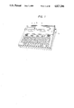
- FIG. 1 is an external view of an electronic typewriter
- FIG. 2 is a constitutional block diagram of an electronic typewriter
- FIG. 3 is a constitutional diagram of a thermal head driver
- FIG. 4 is a constitutional diagram of a motor driver
- FIG. 5 is a diagram showing an example of a character font
- FIG. 6 is an explanatory diagram for AMA control to heat the portion of the pattern A in FIG. 5;
- FIG. 7 is an explanatory diagram for PPM control to heat the portion in the pattern A in FIG. 5;
- FIG. 8 is an explanatory diagram for P'PM control to heat the portion of the pattern A in FIG. 5;
- FIG. 9 is an explanatory diagram for P'PM (3, 2, 1) control to heat the portion of the pattern A in FIG. 5;
- FIG. 10 is an explanatory diagram for P'MP control to heat the portion of the pattern A in FIG. 5;
- FIG. 11 is an explanatory diagram for AMA 3 control to heat the portion of the pattern B in FIG. 5;
- FIG. 12 is an explanatory diagram for A 3 MA control to heat the portion of the pattern B in FIG. 5;
- FIG. 13 is an explanatory diagram for A 2 AMA control to heat the portion of the pattern B in FIG. 5;
- FIG. 14 is an explanatory diagram for A 3 MA 3 control to heat the portion of the pattern B in FIG. 5;
- FIG. 15 is an explanatory diagram for AA 3 MA control to heat the portion of the pattern B in FIG. 5;
- FIG. 16 is an explanatory diagram for A 2 AMA 3 control to heat the portion of the pattern B in FIG. 5;
- FIG. 17 is an explanatory diagram for AM and A'M underline control
- FIG. 18 is an explanatory diagram for control of one serial/lateral dot in the AMA control to heat the portion of the pattern C shown in FIG. 5;
- FIGS. 19-1 to 19-3 are explanatory diagrams for examples of application in FIG. 18;
- FIG. 20 is an explanatory diagram for " "-shape dot control to heat the portion of the pattern D in FIG. 5;
- FIG. 21 is an explanatory diagram for " "-shape dot control to heat the portion of the pattern E in FIG. 5;
- FIG. 22 is an explanatory diagram for " ⁇ "-shape dot control to heat the portion of the pattern F in FIG. 5;
- FIG. 23 is an explanatory diagram for P'P 3 M control to heat the portion of the pattern B in FIG. 5;
- FIG. 24 is an explanatory diagram for P' 3 PM control to heat the portion of the pattern B in FIG. 5;
- FIG. 25 is an explanatory diagram for P'PMP' control to heat the portion of the pattern B in FIG. 5;
- FIG. 26 is an explanatory diagram for P'PMP' 2 control to heat the portion of the pattern B in FIG. 5;
- FIG. 27 is an explanatory diagram for P 2 P'PM control to heat the portion of the pattern B in FIG. 5;
- FIG. 28 is an explanatory diagram for P'P 3 MP' 3 control to heat the portion of the pattern B in FIG. 5;
- FIG. 29 is an explanatory diagram for P' 3 PMP' 3 control to heat the portion of the pattern B in FIG. 5;
- FIG. 30 is an explanatory diagram for P 2 P'PMP' 3 control to heat the portion of the pattern B in FIG. 5;
- FIG. 31 is a diagram for PP' 3 PMP' control to heat the portion of the pattern B in FIG. 5;
- FIG. 32 is an explanatory diagram for one serial/lateral dot control in the P'PM control to heat the portion of the pattern C in FIG. 5;
- FIGS. 33-1 to 33-5 are diagrams showing examples of application in FIG. 32;
- FIG. 34 is a flowchart for the AMA control shown in FIG. 6;
- FIG. 35 is a flowchart for the PPM control shown in FIG. 7;
- FIG. 36 is a flowchart for the P'PM control shown in FIG. 8;
- FIG. 37 is a flowchart for the P'PM (3,2,1) control shown in FIG. 9;
- FIG. 38 is a control flowchart for the portion to obtain the A data in the AMA control
- FIG. 39 is a control flowchart for the first dot in the AMA control.
- FIG. 40 is a flowchart for the AMA 3 control shown in FIG. 11;
- FIG. 41 is a flowchart for the A 3 MA 3 control shown in FIG. 14;
- FIG. 42 is a control flowchart for one serial/lateral dot in the AMA control shown in FIG. 18;
- FIG. 43 is a flowchart for the " "-shape dot control
- FIG. 44 is a flowchart for the " "-shape dot control
- FIG. 45 is a flowchart for the " ⁇ "-shape dot control
- FIG. 46 is a flowchart for the AM and A'M underline control
- FIG. 47 is a flowchart to obtain the P data in the P'PM control
- FIG. 48 is a flowchart to obtain the P' data in the P'PM control
- FIG. 49 is a flowchart to obtain the P' (3, 2, 1) data in the P'PM (3, 2, 1) control;
- FIG. 50 is a flowchart showing the control of the first dot in the P'PM control
- FIG. 51 is a flowchart for the P' 3 MP' 3 control
- FIG. 52 is a flowchart for the P'P 3 M control
- FIG. 53 is a flowchart for the one lateral dot control in the P'PM control
- FIG. 54 is a system flowchart
- FIGS. 55A and 55B are explanatory diagrams of patterns for erasure
- FIG. 56 is a flowchart for erasure (by a zigzag pattern).
- FIG. 57 is a flowchart for the MN control.
- FIG. 58 is a flowchart for manual erasure.
- FIG. 1 is a diagram showing an external view of an electronic typewriter as a thermal transfer printer to which the invention can be applied.
- a thermal head 6 mounted on a carriage 5 of a printer unit 3 is pressed onto a platen through an ink ribbon (not shown) by operating keys arranged in a keyboard unit 1 and the heat is applied.
- the printing is performed by the ink of the ribbon onto a print paper which is fed by the platen.
- An LCD (liquid crystal display) unit 2 to display the content to be printed and a platen knob 4 to manually feed the print paper are also provided.
- the electronic typewriter (thermal transfer printer) in the embodiment can attach a plurality of kinds of ribbons and can discriminate the attachment of the following ribbons by a sensor (not shown) or by an instruction from the key namely, an (ordinary) ink ribbon IR in which the single color printing can be performed at the same ribbon position; a correctable ribbon (self correction ribbon) CR in which the printing and erasure can be performed by the same ribbon; a dual color ribbon DR (refer to Japanese patent Application Nos. 260403/1984 and 298831/1985) in which the ribbon consists of a plurality of layers and a multi-color printing can be selectively performed at the same ribbon position in dependence on the layer to be printed; and the like.
- FIG. 2 shows a constitutional block diagram of the electronic typewriter.
- This unit is the printing apparatus of the electronic typewriter and has the carriage 5 including therein a drive motor.
- the thermal head 6 is mounted in this unit.
- This unit is used as the input unit and has a key matrix.
- This unit displays the information to print or store.
- An LCD is used as a display surface.
- This unit has a controller and a driver to display the data from a CPU 9 onto the LCD 2.
- An AC adapter, nickel cadmium battery, dry cell, and the like can be used as an input power source 8. From this power source, three power sources are produced: a power source (hereinafter, referred to as V cc ) to make the logic circuits including the CPU 9 operative; a power source (hereinafter, referred to as V M ) for the motor of the printer; a power source (hereinafter, referred to as V H ) which is applied to the thermal head.
- V cc a power source
- V M power source
- V H power source
- a control system mainly comprises the CPU 9; an ROM 10 in which a system program and CG, which will be explained hereinlater, are stored; a memory device such as an RAM 11 or the like for a work or text; and a custom IC (gate array hereinafter, referred to as a GA 12) serving as expansion input/output terminals, address decoder, and the like of the CPU 9.
- the RAM 11 has a character count unit 23 to store widths of characters from the CG which are necessary for the control, which will be explained hereinlater.
- Temperature information from a temperature measurement circuit 13 is input to the control system and thereafter, the data which is sent to the thermal head 6 of the printer is transmitted through the GA 12 to a thermal head driver (TH driver) 21.
- TH driver thermal head driver
- This typewriter has therein an interface connector 15.
- the I/F connector 15 can only receive the data from an external host computer in a manner such that this typewriter can be used as a printer through, for example, an interface 16 made by Sentronics Co., Ltd. or an RS-232C 17 so as to print this data.
- the typewriter also has therein a cartridge connector 20 into which a CG cartridge 18 having character styles of the types as data and an RAM cartridge 19 to store registration data can be inserted.
- FIG. 3 shows a constitution of the thermal head driver IC 21 to heat the thermal head shown in FIG. 2.
- V cc1 , V cc2 Input terminals to receive power sources for the logic circuits
- VD 1 , VD 2 Power sources for the driver to drive the thermal head
- GND 1 to GND 7 GND
- CRX Terminal having an CR charging circuit in the outside of the IC.
- a print inhibition signal to inhibit the printing output for the thermal head can be output irrespective of the software when an EN terminal is at the high level at the charge voltage level of C
- the parallel data from the CPU 9 are converted into the serial data by the GA 12 and then transferred to the DIN terminal. Clocks are also sent from the GA 12 to the CK terminal of the TH driver 21. By repeating these operations twenty-four times, the heat data of one time is completely taken into the IC.
- the next operation to transfer the heat data to the driver by previously setting the EN terminal to the low level by a software command, the charges in a capacitor in the outside of the CRX terminal are discharged and the CRX terminal is set to the low level. The time duration to heat is set. Thereafter, the high level signal is sent to the EN terminal. From this time point, the heating operation is started in accordance with the latched data. The thermal head is continuously heated until a set time in the CPU has come or the EN terminal is set to the low level or the capacitor level of the CRX terminal has exceeded a set value.
- the thermal head in the embodiment is constituted in such a manner that twenty-five heads OUT 1 to OUT 25 are vertically arranged in a line.
- the heads are moved, e.g., from the left to the right in FIG. 5, while the heating operations are executed at the recording timings corresponding to the respective dots, thereby performing the recording.
- the shape of head is not limited to this example.
- FIG. 4 shows a constitution of the motor driver IC 14 to drive the motor of the printer.
- Signal lines of the CPU 9 are directly connected to input terminals of the motor driver IC 14 and their outputs are directly connected to the respective phases of the motor 22.
- the double phase excitation is performed in response to a software command.
- the carriage 5 on which the head 6 is mounted moves.
- a reference interval of "heat cycle (one recording timing)" shown in FIG. 6 and the like is specified in accordance with the switching of each excitation.
- FIG. 5 shows an example of a character font stored in the ROM 10 or CG cartridge 18 in FIG. 2.
- the character "A” is expressed by 24 dots (in the vertical direction) ⁇ 32 dots (in the horizontal direction). Each dot is represented by a small circle (o).
- the character "A” is applied with the heating energies in a manner such that the head (any one of the OUT 1 to OUT 25 in FIG. 3) of the portion corresponding to each dot (o) in a time or positional manner is heated once within one heat pulse.
- the head can print the vertically arranged 25 dots of OUT 1 to OUT 25 . By horizontally moving the head, an arbitrary character is printed.
- a constitution of the head is not limited to this example.
- Each area indicated by “A” to “F” denotes a part of the pattern which will be used to explain the driving of the thermal head hereinlater.
- the lateral direction indicates a heat cycle and the vertical direction represents dot lines (the 1st line to the 25th line) corresponding to the heads of one vertical column.
- FIG. 6 is a diagram showing a printing state of the portion A in FIG. 5 on the basis of the heat pulses and heat data.
- the lateral direction of one lattice indicates one heat cycle and the vertical direction represents a distance (size) of one dot.
- a mark (o) indicates the heat data (corresponding to the CG).
- the printing is controlled on the basis of two data consisting of after data (hereinafter, referred to as A data) and main data (hereinafter, referred to as M data) and their pulse widths.
- a data after data
- M data main data
- the A data is heated after the data of the main dot within one heat cycle with respect to the position.
- the pulse width and pulse position of each M data are set to be equal, respectively.
- the pulse width and pulse position of each A data are also set to be equal, respectively.
- the pulse position and the pulse timing are used as the equivalent meaning for convenience of explanation.
- the heat data indicated by the mark (o) corresponds to the M data in a one-to-one correspondence relation.
- the thermal head i.e., the ribbon.
- the heat pulse width of the M data is long, in the case of the continuous dots, the heat is accumulated, so that the heating energy when heating later becomes high.
- the heat pulse width is short, the heating energy of the dot at the start of the heating is low.
- the AMA control since the interval between the A data to the next M data is short, the heat applied by the A data is hardly reduced.
- the AMA control is particularly effective at the ordinary or low temperatures (e.g., 30° C. or less) and the high quality printing can be obtained.
- the CG data is previously read before the start of the heating by one dot. If data exists, only the A data is heated after the M data with respect to the position.
- the thermal head heated by this A data (the first A data in the AMA) executes the printing by the subsequent M data (at the next recording timing).
- the head is certainly warmed by the subsequent A data, so that the printing is surely performed. Further, this state also provides a preparation for the next M.
- the subsequent dot can print by only the M data as shown in FIG. 6.
- FIG. 7 is a diagram for explaining the PPM control in a manner similar to FIG. 6 with respect to the case of printing the pattern A in FIG. 5.
- FIG. 7 shows a printing state by use of the heat pulses and heat data.
- the mark (o) denotes heat data.
- predata is given before the M data called P data with respect to the position.
- the printing is controlled by two P data (one is for the spare data and the other is the auxiliary data of the M data in one heat cycle) and the M data.
- the pulse width and pulse position of each M data are set to be equal, respectively.
- the pulse width and pulse position of each P data are also set to be equal, respectively.
- the heat data indicated by the mark (o) corresponds to the M data in a one-to-one correspondence relation.
- the interval between the first P (spare) data and the next P (auxiliary) data is set to a long interval and the heating energy is dispersed during this interval. Due to this, the printing energies can be uniformed.
- FIG. 8 shows a printing state by the heat pulses and heat data in the case of printing the pattern A in FIG. 5 by the P'PM control.
- the mark (o) denotes heat data.
- the printing is controlled on the basis of pre dash data called P' data having a pulse width different from that of the P data, the P data, and the M data.
- P'PM control the printing is controlled on the basis of pre dash data having a pulse width different from that of the P data, the P data, and the M data.
- this control should be referred to as the APM control in consideration of the foregoing control, it is referred to as the P'PM control for convenience of explanation.
- the P'BM control three kinds of pulse widths and positions exist in one heat cycle.
- the P'PM control is used in the case of the printing having a relatively long heat cycle.
- the heat cycle is long, if the A data and the next M data are printed in the heat cycle before the M data, the interval between the A data and the M data becomes too long, so that the warmed head is unexpectedly cooled.
- the heat pulse of the P data is interposed before the M data within the same heat cycle as that of the P" data M at a position near the end of the heat cycle before the M data, thereby constituting the P'PM control. With this control, the head warmed by the P' data can print by the P data and M data. Further, the second dot and subsequent dots can be printed by only the M data.
- the P'PM control is particularly effective at, e.g., the ordinary or high temperatures.
- FIG. 9 shows a printing state by the heat pulses and heat data in the case of printing the pattern A in FIG. 5 by the P'PM (3, 2, 1) control.
- the P'PM (3, 2, 1) control is constituted by three data consisting of the pre dash data called the P' data, the pre data called the P' data, and the main data called the M data, and three kinds of heat pulse widths and pulse positions.
- the P'PM (3, 2, 1) control is used in the case of the printing having a relatively long heat cycle.
- the P'PM (3, 2, 1) control is executed.
- the printing energies can be uniformed. Namely, for the first dot, the head warmed by the first P' data in the one-preceding heat cycle performs the printing operation by the P data, M data, and next P' data (total three pulses) within one heat cycle of the M data.
- the second dot is printed by the P data and the second M data (total two pulses) within one heat cycle of the second M data.
- the third and subsequent dots can be printed by only the M data (total one pulse).
- the heating energies to be applied are concentrated to the first and second dots.
- FIG. 10 shows a printing state by the heat pulses and heat data in the case of printing the pattern A in FIG. 5 by the P'MP control.
- the P'MP control relates to an example of application of the P'PM control which is effective at ordinary or high temperatures. In this example, the positions of the P and M data in P'PM are exchanged.
- FIG. 11 shows a printing state by the heat pulses and heat data in the case of printing the pattern B in FIG. 5.
- the mark (o) denotes heat data.
- the heat can easily escape in the vertical direction (refer to FIG. 11(b)) and it is difficult to certainly print.
- This drawback can be prevented by slightly heating by the A data the upper and lower positions at which the heating energies escape with respect to the first dot of a lateral line such that no other dot exists in the upper and lower directions like the pattern B in FIG. 5.
- the first dot can be surely heated and the high quality printing is derived.
- the AMA 3 control is particularly suitable in the high speed printing mode and, further, it is particularly effective at the ordinary temperature for the AMA control mentioned above.
- the A 3 MA control relates to an example of application of the foregoing AMA 3 control.
- FIG. 12 shows the A 3 MA control in the case of printing the pattern B in FIG. 5. According to the method of the A 3 MA control, the peripheral temperature of the dot to be printed is raised before the printing.
- FIG. 13 likewise shows the A 2 AMA control when printing the pattern B in FIG. 5.
- the head is slowly warmed from the timing which is preceding to the printing dot by two dots.
- FIG. 14 shows a printing state by the heat pulses and heat data in the case of printing the pattern B in FIG. 5 by the A 3 MA 3 control
- the mark (o) denotes heat data.
- the heat diffusion also occurs in the AMA 3 control described in FIG. 11. Therefore, it is necessary to apply higher heating energies than those in the AMA 3 control.
- the peripheral temperature of the dot to be printed is previously raised and the position where the heat can escape is heated by the A data. By this method, the first dot can be certainly heated at low temperatures.
- FIG. 15 similarly shows the AA 3 MA control when printing the pattern B in FIG. 5.
- the central and peripheral positions of the printing dot of the head are previously warmed from the timing which is preceding to the printing dot by two dots, thereby increasing the heating energies to be applied.
- FIG. 16 likewise shows the A 2 AMA 3 control for the pattern B in FIG. 5.
- the peripheral positions of the printing dot of the head are previously warmed from the timing which is two-dot preceding to the dot to be heated, thereby increasing the heating energies to be applied.
- An underline is printed by continuously heating two vertical dots At this time, when the AMA control shown in FIG. 6 is used, the heat is accumulated in the head. To prevent this, the average value of the heating energies to be applied needs to be reduced. However, since the widths of A data and M data also serve as the heating periods of time for characters, the heat pulse widths cannot be reduced. Therefore, by heating the M data every other dot and by deleting the post A data in the AMA control, the heating energies to be applied are reduced and the heat accumulation is suppressed.
- FIG. 17(b) shows the foregoing AM underline control.
- the applying energy at the first dot of the underline from which the heat accumulation was eliminated is low. Therefore, there is a possibility such that the lack of printing at the first dot occurs at low temperatures.
- the data which is obtained by widening the pulse width of A in the AM underline control is set to A' and used to preheat the first dot. Thus, the first dot of the underline can be more certainly printed.
- FIG. 17(a) shows the A'M control.
- FIG. 18 shows a printing state by the heat pulses and heat data in the case of printing a one serial/parallel dot line by the AMA control.
- the mark (o) denotes heat data.
- the heating energies escape in the directions as shown by arrows at low temperatures, so that there is a possibility such that the printing concentration is small or is not performed.
- FIGS. 19-1 to 19-3 show examples of the application of this control.
- FIG. 19-1 shows the case where the A data is added at the interval of one dot.
- FIG. 19-2 shows the case where the A data is added to the upper and lower lines of the line where the dot information to be printed exists, namely, in the upper and lower heat escaping directions.
- FIG. 19-3 shows the case of a combination of FIG. 18(a) and FIG. 19-2 in which the A data is added at intervals of one dot.
- FIG. 20 shows a printing state by the heat pulses and heat data in the case of printing the pattern D in FIG. 5 at a high quality.
- the A data is heated from the timing before the actual CG data and the head is warmed.
- the heat escapes in the directions indicated by arrows, there is no need to warm the head. Therefore, when the M data exists in the upper and lower directions, the first A data (indicated by broken lines) at the center is not heated.
- FIG. 21 shows a printing state in the case of printing the pattern E in FIG. 5.
- the A data shown by broken lines
- FIG. 22 shows a printing state in the case of printing the pattern F in FIG. 5.
- the center is a dot to be printed and differs from the " ⁇ "-shape in which the center is a blank.
- the heating energies move toward the center from the upper, lower, and front positions thereof. Therefore, when the M data is heated, the heating energies are concentrated and there is a possibility such that a variation in printing occurs.
- the A data is heated to a degree such as not to form a blank portion, thereby reducing the heating energies and uniforming the whole energy.
- FIG. 23 shows a printing state by the heat pulses and heat data in the case of printing the pattern B in FIG. 5.
- the mark (o) denotes heat data.
- the first dot when no heat data exists at the upper and lower positions, the heat is diffused in the upper and lower directions, so that it is difficult to certainly print. Therefore, by heating the heat escaping positions by the P data, the diffusion of the heat can be prevented and the first dot can be certainly heated.
- the pulse widths of the P and P' data are different.
- This P'P 3 M control is effective at high or ordinary temperatures in the case of the P'PM control which is suitable in the low speed printing mode.
- the P' 3 PM control is shown in FIG. 24.
- the P' 3 PM control relates to a method whereby the peripheral temperature of the dot to be printed is previously raised.
- FIG. 25 shows the P'PMP' control. According to this control, the printing energy for the first dot in the P'PM control which has been described in FIG. 8 is increased by the amount corresponding to the second P' data, thereby correcting the diffusion of the heating energy which is applied to the first dot. Thus, the printing of a good quality can be derived.
- FIG. 26 shows the P'PMP' 2 control. According to this control, the heat diffusion at the upper and lower peripheral positions of the M data of the first dot in the P'PM control which has been described in FIG. 8 is prevented by two P' data, thereby protecting P'PM.
- FIG. 27 shows the P 2 P'PM control. According to this control, there is an effect such that by applying two P data just before the execution of the P'PM control, the head is previously warmed, thereby suppressing the heat diffusion which occurs at the start of the P'PM control.
- FIG. 28 shows a printing state by the heat pulses and heat data in the case of printing the pattern B in FIG. 5 by the P'P 3 MP' 3 control.
- the mark (o) denotes heat data.
- the P'PM (3, 2, 1) control shown in FIG. 9 it is considered that in the case of the first dot when no heat data exists at the upper and lower positions, the heat is diffused in the upper and lower directions, so that it is difficult to certainly print. Therefore, by heating the heat diffusing positions by the P data and P' data, the heat diffusion can be prevented and the first dot can be further surely heated.
- the P'P 3 MP' 3 control is particularly suitable in the low speed printing mode.
- FIG. 29 shows the P' 3 PMP' 3 control.
- the head is warmed at the first time at the upper or lower position.
- the diffusion of the heat of the M data is prevented at the second time. In this manner, the heating efficiency is raised.
- FIG. 30 shows the P 2 P'PMP' 3 control.
- the P data at the upper and lower positions are preheated, and, at the P' data just after the M data, the P' data at the upper and lower positions are further heated to prevent the heat diffusion in the upper and lower directions, thereby uniforming the printing energies
- FIG. 31 shows the PP' 3 PMP' control.
- the heating efficiency of the P' data for the preheat in the P'PM (3, 2, 1) control shown in FIG. 9 deteriorates due to the heat diffusion. Therefore, according to the PP' 3 PMP' control, in order to improve the heating efficiency, the P data is previously heated and the P' data at the upper and lower positions are then heated, thereby preventing the heat diffusion.
- FIG. 32 shows a printing state by the heat pulses and heat data in the case of printing the pattern C in FIG. 5.
- the mark (o) denotes heat data.
- the M data is ordinarily heated. Therefore, particularly, in the low speed printing mode at low temperatures, the heat escapes in the upper and lower directions, so that there is a possibility such that the printing concentration is small or the printing is not performed.
- FIGS. 33-1 to 33-5 show examples of application of this control.
- FIG. 33-1 shows the case where the P data and P' data are added at intervals of one dot (within one heat cycle) in the upper and lower heat escaping directions.
- FIG. 33-2 shows the case where the P data is added to the centers of the printing dots at intervals of one dot and at the same time, the P' data is added at intervals of one dot in the upper and lower heat escaping directions.
- FIG. 33-3 shows the case where the P data is added to the centers of the printing dots and at the same time, the P' data is added at intervals of one dot.
- FIG. 33-4 shows the case where the control is switched at intervals of three dots
- the first dot is heated by the P data, M data, and P' data.
- the second dot is heated by the P data and M data.
- the third dot is heated by only the M data.
- FIG. 33-5 shows the case where the P data and P' data are alternately added to the centers of the printing dots.
- the "data heat” means that a drive pulse is given and whether data is actually printed or not is determined in dependence on whether the data has been turned on or off when the drive pulse was given.
- FIG. 34 is a control flowchart for the AMA control shown in FIG. 6.
- the processing routine for the AMA control in step S1 is started.
- step S2 a width of character to be printed (i.e., a length in the lateral direction shown in FIG. 5; in this case, 32 dots) is fetched from the CG (ROM 10 or CG cartridge 18) and set into the character count unit 23 in the RAM 11.
- the character width can be changed in accordance with a font or the like.
- step S3 the excitation phase of the motor is switched to move the carriage 5 having the thermal head 6 by the motor 22 by only the distance of one heat cycle corresponding to the width of one frame shown in FIGS. 6 to 33-5. Namely, the carriage advances by the distance corresponding to one heat cycle by executing the switching operation in steps S3 to S9 once.
- step S4 the substantial printing data, i.e., the M data corresponding to the mark (o) shown in FIG. 5 is obtained from the CG.
- step S6 the M data which was actually obtained in step S4 is heated.
- step S7 the A data is heated.
- step S6 the M data is heated (step S6) in the control.
- step S8 the count data in the character count unit 23 is decreased by "1".
- step S9 a check is made to see if the character count value is "0" or not. If it is "0", this means that the character to be printed has been finished. Therefore, the processing routine ends in step S10.
- FIG. 35 is a flowchart for the PPM control shown in FIG. 7.
- the printing is started in step S1.
- a width in character to be printed is obtained from the CG and set into the character count unit in the RAM in step S2.
- the excitation phase of the stepping motor is switched in step S3.
- the M data is obtained from the CG in step S4. These processes are the same as those in FIG. 34.
- the next step S5 the A (P) data is made by use of the previous M data, the present M data, and the next M data. This routine will be explained hereinafter. However, the A data is used in place of the P data for convenience of explanation.
- the A (P) data obtained in step S5 is heated.
- the M data obtained in step S4 is heated in step S7.
- step S8 The character count value is decreased by "1" in step S8.
- step S9 a check is made to see if the character count value is "0" or not. If it is "1”, the processing routine is returned to step S3. If it is "0”, this means that the printing of one character is finished, so that the processing routine ends in step S10.
- FIG. 36 is a flowchart for the P'PM control shown in FIG. 8. Since the processes in steps S1 to S4 are the same as those in FIGS. 34 to 36, their descriptions are omitted.
- step S5 the P data is produced by the previous M data and the present M data. This processing routine will be explained hereinlater.
- step S6 the P data formed in step S5 is heated.
- step S7 the M data obtained in step S4 is heated.
- step S8 the P' data is made by the present M data and the next M data. This processing routine will be explained hereinlater.
- step S9 the P' data obtained in step S8 is heated.
- step S10 the character count value is decreased by "1".
- step S11 a check is made to see if the character count value is "0" or not. If it is "1”, the processing routine is returned to step S3. If it is "0”, this means that the printing of one character has been finished, so that the processing routine ends in step S12.
- FIG. 37 shows a flowchart for the P'PM (3, 2, 1) control shown in FIG. 9. Since the processes in steps S1 to S4 are the same as those mentioned above, their descriptions are omitted.
- step S5 the presence or absence of the previous P' data is checked. If the previous P' data exists, the P data is turned on in step S7. Namely, this means that when the P data is then heated, it is printed.
- step S8 follows. If the previous P' data does not exist, the P data is formed by the previous M data and the present M data in step S6 (which will be explained hereinlater). In step S8, the P data formed in steps S6 and S7 is heated. In step S9, the M data obtained in step S4 is heated.
- step S10 the P' data is produced by the previous M data, the present M data, and the next M data (which will be explained hereinlater).
- step S11 the P' data obtained in step S10 is heated.
- step S12 the character count value is decreased by "1”.
- step S13 a check is made to see if the character count value is "0" or not. If it is not "0”, the processing routine is returned to step S3. If it is "0", this means that the printing of one character has been finished, so that the processing routine ends in step S14.
- FIG. 38 is a flowchart for the step of obtaining the A data (S5 in FIG. 34) in the AMA control.
- a check is made in step S2 to see if the M data exists or not at the printing position of the printing head at the present excitation phase which was switched in the excitation phase switching step S3 in FIG. 34 (hereinafter, this M data is referred to as the present M data). If it exists, the processing routine advances to step S3 and a check is made to see if the previous M data (the dot which is preceding to the present printing position by one dot) exists or not. If it does not exist, the A data is turned on in step S4.
- step S7 The turn-on of the A data means that the A data is actually printed by heating it in step S7 in FIG. 34. In this case, the latter A data in the AMA is formed. If the previous M data exists in step S3, this means that the M data continuously exists, so that step S7 follows.
- step S5 follows and the CG for the next dot is previously read. This read data is set to the next M data.
- step S6 the presence or absence of the next M data is checked. If the next M data exists, the A data is turned on in step S4. The A data formed in this step is the first A data in the AMA. If the next M data does not exist in step S6, step S7 follows.
- step S7 the first dot is controlled (which will be explained in conjunction with FIG. 39).
- step S8 the one serial/lateral dot control is executed (which will be explained in FIG. 42).
- step S9 the " "-shape dot control is performed (which will be explained in FIG. 43).
- step S10 the " "-shape dot control is executed (which will be explained in FIG. 44).
- step S11 the " ⁇ "-shape dot control is carried out (which will be explained in FIG. 45).
- FIG. 39 is a flowchart showing the control for the first dot in the AMA control.
- step S1 the control is started.
- step S2 the ambient temperature of the apparatus is measured by the temperature measurement circuit (13 in FIG. 2).
- step S3 a check is made to see if the temperature is low or not. If it is low, the A 3 MA 3 control is executed in step S5.
- step S6 then follows. If it is not low, the AMA 3 control is performed in step S4 and the control ends in step S6.
- FIG. 40 is a flowchart showing the AMA 3 control. In this case, the control shown in FIG. 11 is cited as an example.
- step 1 the control is started.
- step S2 the presence or absence of the M data is checked. If the M data does not exist, step S6 follows. If it exists, a check is made in step S3 to see if the M data exists at the upper and lower positions or not. If either one of or both of the M data exist, step S6 follows. If no M data exists, the presence or absence of the A data is checked in step S4. If the A data does not exists, step S6 follows. If the A data exists, the A data at the upper and lower positions are turned on in step S5 and the processing routine ends in step S6.
- FIG. 41 shows a flowchart for the A 3 MA 3 control.
- the control shown in FIG. 14 is cited as an example.
- step S1 the control is started.
- step S2 the presence or absence of the M data is checked. If the M data does not exist, step S6 follows. If the M data exists, a check is made in step S3 to see if the M data at the upper and lower positions exist or not. If either one of or both of the M data exist, step S7 follows. If no M data exists, the presence or absence of the A data is checked in step S4. If the A data does not exist, step S7 follows. If it exists, the A data at the upper and lower positions are turned on in step S5. Then, step S7 follows.
- step S6 the presence or absence of the A data at the upper and lower positions is checked. If no A data exists, step S4 follows. If they exist, step S7 follows and the control ends.
- FIG. 42 is a flowchart showing the one serial/lateral dot control in the AMA control.
- the control shown in FIG. 18 is cited as an example.
- step S1 the control is started.
- step S2. a check is made to see if the M data exists or not. If the M data does not exist, step S5 follows. If the M data exists, the presence or absence of the M data at the upper and lower positions is checked in step S3. If either one or of both of the M data at the upper and lower positions exist, step S5 follows. If no M data exists, the A data at the upper and lower positions (in the cases in FIGS. 19-1 to 19-3) are turned on in step S4. The processing routine ends in step S5.
- FIG. 43 is a flowchart for the " "-shape dot control. An example of this control already been described in FIG. 20.
- step S1 the control is started.
- step S2 the presence or absence of the A data is checked. If the A data does not exist, step S6 follows. If the A data exists, the presence or absence of the M data is checked in step S3. If the M data exists, step S6 follows. If the M data does not exist, the presence or absence of the M data at the upper and lower positions is checked in step S4. If no M data exists, step S6, follows. If they exist, the A data is turned off in step S5 and the control ends in step S6. Thus, the A data indicated by the broken lines shown in FIG. 20 is not printed and the " "-shape is certainly printed.
- FIG. 44 is a flowchart for the " "-shape dot control. An example of the control has already been described in FIG. 21.
- step S1 the control is started.
- step S2 the presence or absence of the present A data is checked. If the present A data does not exist, step S11 follows. If it exists, the presence or absence of the present M data is checked in step S3. If the present M data exists, step S11 follows. If the present M data does not exist, the presence or absence of the previous M data is checked in step S4. If the previous M data does not exist, step S11 follows. If the previous M data exists, the presence or absence of the M data at the upper position is checked in step S5. If the upper M data does not exist, step S10 follows.
- step S6 the presence or absence of the M data at the lower position is checked in step S6. If the lower M data exists, step S11 follows. If it does not exist, the CG for the next dot is previously read in step S7. In step S8, the presence or absence of the M data for the next dot is checked. If it does not exist, step S11 follows. If the M data for the next dot exists, the A data is turned off in step S9 and step S11 follows.
- step S10 the presence or absence of the lower M data is checked. If it exists, step S7 follows. If it does not exist, step S11 follows and the control ends.
- FIG. 45 is a flowchart for the " ⁇ "-shape dot control. An example of this control has already been described in FIG. 22.
- step S1 the control is started.
- step S2 the presence or absence of the present M data is checked. If it does not exist, step S9 follows. If it exists, step S3 follows and the presence or absence of the M data at the upper and lower positions is checked. If either one of or both of the upper and lower M data do not exist, step S9 follows. If both of the upper and lower M data exist, the presence or absence of the previous M data is checked in step S4. If the previous M data does not exist, step S9 follows. If the previous M data exists, the CG for the next data is previously read in step S5. The presence or absence of the next dot is checked in step S6. If the next dot does not exist, step S9 follows.
- step S7 If the next dot exists, the upper and lower M data are turned off in step S7.
- step S8 the A data is turned on.
- step S9 the control ends. Namely, if the M data exist around the present M data which was checked in step S2, these M data are turned off. However, in this state, the center of the dot becomes a blank. Therefore, only the A data is turned on so as to avoid the concentration of the heating energies.
- FIG. 46 is a flowchart for the AM underline control and the A'M underline control.
- step S1 a check is made to see if the dot is the 0th dot or not.
- step S4 a check is made to see if the preheat for the first dot of an underline is executed or not. If NO, step S4 follows. If the preheat is performed, the A' data (whose pulse width and pulse position are different from those of the A data) is heated in step S3. Then, step S7 follows. In step S4, a check is made to see if the dot is the even number dot or not. If YES, the A data is heated in step S5 and step S7 follows. If the dot is the odd number dot, the M data is heated in step S6 and the control ends in step S7.
- FIG. 47 is a flowchart showing the process to obtain the P data in step S5 in the P'PM control shown in FIG. 36.
- the process to obtain the P data is started in step S1.
- step S2 the presence or absence of the present M data is checked. If the present M data does not exist, step S5 follows. If it exists, the presence or absence of the previous M data is checked in step S3. If the previous M data exists, step S5 follows. If the previous M data does not exist, the P data is turned on in step S4.
- step S5 the first dot is controlled (which will be explained hereinlater in FIG. 50).
- step S6 one serial/lateral dot is controlled (which will be explained hereinlater in FIG. 51).
- the processing routine ends in step S7.
- FIG. 48 is a flowchart for the process to obtain the P' data in the P'PM control which has been described in step S8 in FIG. 36.
- step S1 the process to obtain the P' data is started.
- step S2 the presence or absence of the present M data is checked. If the present M data exists, step S6 follows. If it does not exist, the CG for the next dot is previously read in step S3 and the read data is set to the next M data.
- step S4 the presence or absence of the next dot (M data) is checked. If the next dot does not exist, step S6 follows. If it exists, the P' data is turned on in step S5 and the processing routine ends in step S6.
- FIG. 49 is a flowchart for the process to obtain the P' (3, 2, 1) data in the P'PM (3, 2, 1) control described in step S10 in FIG. 37.
- step S1 the process to obtain the P' (3, 2, 1) data is started.
- step S2 the presence or absence of the present M data is checked. If the present M data exists, step S6 follows. If the present M data does not exist, the CG for the next dot is previously read in step S3.
- step S4 the presence or absence of the next dot (M data) is checked. If the next dot does not exist, step S7 follows. If the next dot exists, the P' (3, 2, 1) data is turned on in step S5 and step S7 follows.
- step S6 the presence or absence of the previous M data is checked. If it does not exist, step S5 follows. If it exists, the processing routine ends in step S7.
- FIG. 50 is a flowchart showing the control for the first dot in the P'PM control.
- step S1 the control is started.
- step S2 the peripheral temperature of the apparatus is sensed by the temperature measurement circuit (13 in FIG. 2).
- step S3 a check is made to see if the temperature is low or not. If it is not low, the P'P 3 M control is performed in step S5 (which will be explained hereinlater in FIG. 51). Then, step S6 follows. If the temperature is low, the P'P 3 MP' 3 control is executed in step S4 (which will be explained hereinlater in FIG. 52). The processing routine ends in step S6.
- FIG. 51 is a flowchart for the P'P 3 MP' 3 control shown in step S4 in FIG. 50.
- step S1 the control is started.
- step S2 the presence or absence of the M data is checked. If the M data does not exist, step S7 follows. If the M data exists, the presence or absence of the upper and lower M data is checked in step S3. If either one of or both of the upper and lower M data exist, step S7 follows. If no M data exists, the presence or absence of the P data is checked in step S4. If the P data does not exist, step S7 follows. If the P data exists, the upper and lower P data are turned on in step S5. The upper and lower P' data are turned on in step S6. The control ends in step S7.
- FIG. 52 is a flowchart for the P'P 3 M control shown in step S5 in FIG. 50.
- step S1 the control is started.
- step S2 the presence or absence of the M data is checked. If the M data does not exist, step S6 follows. If the M data exists, the presence or absence of the upper and lower M data is checked in step S3. If either one of or both of the upper and lower M data exist, step S6 follows. If no M data exists, the presence or absence of the P data is checked in step S4. If no P data exists, step S6 follows. If the P data exists, the upper and lower P data are turned on in step S5. The control ends in step S6.
- FIG. 53 is a flowchart showing the one serial/lateral dot control in the P'PM control described in FIGS. 36 and 47.
- step S1 the control is started.
- step S2 the presence or absence of the present M data is checked. If the present M data does not exist, step S6 follows. If it exists, the presence or absence of the upper and lower M data is checked in step S3. If either one of or both of the M data exist, step S6 follows. If no M data exists, the P data is turned on in step S4. The P' data is turned on in step S5. The control ends in step S6.
- step S1 the power source of the apparatus is turned on.
- step S2 the whole apparatus such as various kinds of data in the RAM 11 and the like is initialized.
- This embodiment will be explained with respect to the thermal printed as an example.
- various kinds of ribbons such as ordinary ink ribbon IR, correctable ribbon CR in which the printing and erasure can be performed by the same ribbon, and dual color ribbon DR in which the ribbon is formed of a plurality of layers (the invention is not limited to this constitution) and the printing can be performed in two or more colors can be selectively mounted to the carriage 5.
- step S3 the input from the keyboard 1 or the input of data from the I/F connector 15 is detected If the data to be printed exists, step S4 follows and a check is made to see if the ribbon mounted to the carriage is the CR ribbon or not. This discrimination is made by the data from a ribbon sensor (not shown) or by the data such as kind, color, or the like of the ribbon which is indicated by a signal from the keyboard or the like, namely, from signal generating means for generating a signal representative of the ribbon. If NO in step S4, step S17 follows and a check is made to see if the ribbon is the DR ribbon or not. If the ribbon has been decided to be the CR ribbon in step S4, step S5 follows.
- step S5 a check is made to see if the input key is the erasure key or not. If the erasure key has been input, step S29 follows and the erasing operation is executed. If NO in step S5, step S6 follows.
- step S6 a check is made to see if the temperature is a high temperature of, e.g., 30° C. or higher or not on the basis of the data from the temperature measurement circuit 13 provided for the apparatus. If it is determined that the temperature is 30° C. or higher in step S6, the PPM control described in FIGS. 7 and 35 is selected in step S7. Then, the printing is performed in step S28.
- step S8 follows and the AMA control described in FIGS. 6 and 34 is selected. Further, a check is made in step S9 to see if the temperature is low (e.g., 14° C. or lower) or not. The process in step S9 is the same as step S3 in FIG. 39. If the temperature is not low, namely, if it is the ordinary temperature (e.g., 14° C. to 30° C.) in step S9, step S10 follows and the AMA 3 control described in FIGS. 11 and 40 is executed. Then, step S13 follows. If it is decided that the temperature is low in step S9, step S11 follows and the A 3 MA 3 control described in FIGS. 14 and 41 is performed.
- step S9 follows and the A 3 MA 3 control described in FIGS. 14 and 41 is performed.
- step S12 follows and the one serial/lateral dot control in the AMA control shown in FIGS. 18, 19-1 to 19-3, and 42 is executed.
- steps S13 and S14 the AM and A'M underline controls shown in FIGS. 17 and 46 are executed.
- steps S15 and S16 the " "-, " "-, and " ⁇ "-shape dot controls shown in FIGS. 20 to 22 and 43 to 45 are performed.
- step S17 follows. If it is decided that the DR ribbon has been mounted in step S17, step S18 follows. In step S18, a check is made to see if a print color has been designated by the key input or color designation command data or the like or not. If a color (e.g., blue) has been designated, namely, if the ink on the recording paper side in the ink layer has been designated, step S25 follows. If no color is designated, namely, if the ink (black) on the thermal head side in the ink layer has been designated, step S19 follows. The process in step S19 is the same as step S3 in FIG. 50.
- a print color e.g., blue
- step S19 if the temperature is determined to be low on the basis of the data from the temperature measurement circuit 13 in FIG. 2, step S22 follows. If the temperature is not low, step S20 follows and the P'PM control described in FIGS. 8 and 36 is selected. In step S21, the P'P 3 M control described in FIGS. 23 and 52 is executed. The printing is performed in step S28.
- step S22 follows and the P'PM (3, 2, 1) control described in FIGS. 9 and 37 is selected.
- step S23 the P'P 3 MP' 3 control shown in FIGS. 28 and 51 is executed.
- step S24 the one serial/lateral dot control in the P'PM control shown in FIGS. 32 and 53 is executed and the printing is performed in step S28.
- step S25 a check is made to see if the temperature is high or not. If it is high, the PPM control described in FIGS. 7 and 35 is selected. If the temperature is not high, the AMA control described in FIGS. 6 and 34 in step S26 is selected and the printing is performed in step S28. After completion of the process in step S28, the processing routine is returned from step S31 to S3.
- FIGS. 55A and 55B show examples of font patterns for erasure stored in the ROM 10. Practically speaking, each of these patterns consists of 24 ⁇ 8 dots and this pattern is repetitively used. For the pattern to be erased, if the ink which was all recorded by being heated by the M data is peeled off, there is a fear such that the heating energies are accumulated and the ribbon is sticked to the paper or a dirt occurs.
- the N data obtained by reducing the heat pulse width of the M data to the interval of one dot in the lateral direction is heated. Further, since the erasing energy with respect to the first dot is low, by starting the heating from the timing which is preceding by two dots, the erasing energy of the first dot rises and this dot can be certainly erased. This erasure can be accomplished by use of the pattern shown in FIGS. 55A or 55B.
- FIGS. 55A and 55B show the fonts of the zig-zag boxes which are used in the erasing mode.
- the dots are thinned out at intervals of one dot in each of the vertical and lateral directions.
- the first erasing operation is executed in FIG. 55A.
- the font of FIG. 55B is used.
- the font of FIG. 55B is opposite to the font of FIG. 55A.
- the erasure is performed by shifting the M and N data positions by one dot at the second time as compared with the first erasing time.
- the using order of the fonts of FIGS. 55A and 55B may be reversed.
- the printed character can be certainly erased by executing the erasing process twice by use of the opposite fonts.
- the erasure span is determined by a width of character stored in the buffer.
- the buffer is filled with characters, the characters are sequentially deleted from the buffer.
- the operating mode enters the manual erasinq mode. In the manual erasing mode, this mode needs to be informed to the operator and the width of the character to be erased needs to be input by the key.
- the erasure span of the key-in character is obtained by the font and pitch (whole width and double width) which are being displayed at present.
- the character of only the erasure span obtained can be erased. Namely, the operator can freely select the erasure span and erase the character of the erasure span.
- FIG. 56 is a flowchart for erasure in step S29 in FIG. 54.
- step S1 the MN dot pattern 1 is set. In this case, the dots and heat pattern in FIG. 55A are used.
- step S3 the MN control (FIG. 57) is executed and the first erasure is performed.
- step S4 the thermal head (carriage) 6 which moved in association with the erasing operation is returned to the first erasure starting position.
- step S5 the MN dot pattern 2 is set. In this case, the dots and heat pattern in FIG. 55B are used.
- step S6 the MN control (FIG. 57) is executed and the second erasure is performed.
- the processing routine ends in step S7.
- the heating energies can be also further changed in a plurality of erasing operations as mentioned above in the erasure.
- the heating energies can be held to a constant proper value every time. This method is particularly useful in the case of using the foregoing CR ribbon.
- FIG. 57 is a flowchart for the MN control.
- step S1 the control is started.
- step S2 a width of character to be erased is obtained from the CG and set into the character count unit 23 in the RAM 11.
- step S3 the character count value obtained in step S2 is increased by "2". Thus the erasure can be performed from the timing which is preceding to the character by two dots.
- step S4 the excitation phase of the stepping motor is switched.
- step S5 a check is made to see if the character count value obtained in steps S2 and S3 is the even number or the odd number. If it is the odd number, step S9 follows. If it is the even number, the M data is obtained in step S6.
- step S7 the heat pulse width of the M data is derived.
- step S8 the M data obtained in steps S6 and S7 is heated. Then, step S12 follows.
- step S9 the N data is obtained.
- step S10 the heat pulse width of the N data is obtained.
- step S11 the N data obtained in steps S9 and S10 is heated. Then, step S12 follows.
- step S12 the character count value is decreased by "1".
- step S13 a check is made to see if the character count value is "0" or not. If it is not "0”, the processing routine is returned to step S4. If it is "0”, the control ends in step S14.
- FIG. 58 is a flowchart for manual erasure.
- step S1 the processing routine is started.
- step S2 a message is displayed by the LCD to inform the operator of the fact that the manual erasing mode has been set.
- step S3 a check is made to see if the key input has been made or not. If NO, step S3 is repeated. If the key input has been made, a check is made in step S4 to see if it indicates the END key or not. If it is the END key, step S8 follows. If NO, a check is made in step S5 to see if the input key is the character key or not. If NO, the processing routine is returned to step S3. If it is the character key, a width of character corresponding to the input key is obtained from the CG to thereby obtain the erasure span in step S6. In step S7, the erasing operation is performed by only the amount of the erasure span obtained in step S6. Then, step S3 follows.
- step S8 the message displayed on the LCD is cleared and the end of manual erasing mode is informed to the operator.
- the processing routine ends in step S9.
- the printer which can perform the very high quality recording can be provided.
- the very high quality recording can be performed even in the heat cycles other than the heat cycle (recording timing) of the dot as the data to be recorded.
- a thermal transfer printer comprising: heating energy generating means for generating heating energies; means for transferring dot information to be recorded; and control means for controlling the heating energy generating means in a manner such that when recording the dot information transferred by the transferring means, after the first preheating energies were generated in the first recording cycle prior to the dot information to be recorded in the second recording cycle, the second preheating energies different from the first preheating energies are further generated before the heating energies corresponding to the dot information are generated in the second recording cycle.
- the heating energies by uniforming the heating energies, the high quality recording can be performed.
- one dot in the left edge portion of a recording pattern particularly, one independent dot in each of the upper and lower directions can be certainly recorded.
- the preheat is given, and in a predetermined heat cycle, the heating energies corresponding to the dot information to be recorded are not generated, so that a very high quality underline can be recorded.
- the underline can be recorded from the beginning at a high quality.
- the concentration of the heating energies can be prevented, so that the underline of a very quality can be recorded.
- the concentration of the heating energies can be prevented. Therefore, the heating energies can be independently applied to the characters and underline. Both of the characters and underline can be printed at a high quality.
- the underline of a very high quality can be recorded.
- the underline can be recorded at a high quality from the beginning.
- the concentration of the heating energies can be prevented, so that the underline of a very high quality can be recorded. Due to this, not only by reducing the heat pulse width but also by eliminating the heat pulses within one heat cycle, the concentration of the heating energies can be prevented. Therefore, the heating energies can be independently applied to the characters and underline, so that both of the characters and underline can be printed at a high quality.
- the preheat to record the dots in the right direction is not performed, so that the high quality recording without deformation can be executed.
- a printer comprising: heating energy generating means for generating heating energies; reading means for reading out dot information indicative of a pattern to be recorded; and control means for controlling the heating energy generating means in a manner such that in the case where the pattern which was read out by the reading means is pattern in which the dot information exists at least three peripheral directions including the dot information in the recording direction, the preheating energies to record the dot information in the recording direction are not generated.
- the heating energies are reduced to a degree so as not to form a blank the center with respect to that dot information, so that even in the case of a " ⁇ "-shape dot pattern, the high quality recording can be performed.
- a printer comprising: heating energy generating means for generating heating energies; reading means for reading out dot information indicative of a pattern to be recorded; and control means for controlling the heating energy generating means in a manner such that in the pattern which was read out by the reading means, in the case of recording the dot information in which the dot information exists in four peripheral directions, only the preheating energies to record the dot information in the recording direction are generated within the cycle to record the relevant dot information, or to provide a control method for such a printer.
- the invention by correcting the heating energies for not only the first dot but also a few dots, it is possible to provide a thermal transfer printer which can perform the very high quality recording. By continuously correcting the heating energies, the recording can be certainly executed even at the start of the recording at low temperatures or the like.
- the independent dot information in the recording cycle before the recording cycle of the dot information to be recorded, by applying additional preheating energies in the further upper or lower direction of the preheating energies to be applied, in particular, the independent dot information can be certainly recorded.
Abstract
Description
Claims (18)
Applications Claiming Priority (12)
| Application Number | Priority Date | Filing Date | Title |
|---|---|---|---|
| JP31264686A JPS63166563A (en) | 1986-12-27 | 1986-12-27 | Thermal transfer printer |
| JP31264786A JPS63166564A (en) | 1986-12-27 | 1986-12-27 | Thermal transfer printer |
| JP61312644A JP2682980B2 (en) | 1986-12-27 | 1986-12-27 | Output device |
| JP31265086A JPS63166566A (en) | 1986-12-27 | 1986-12-27 | Thermal transfer printer |
| JP31264186A JPS63166560A (en) | 1986-12-27 | 1986-12-27 | Thrmal transfer printer |
| JP61-312641 | 1986-12-27 | ||
| JP31264886A JP2637406B2 (en) | 1986-12-27 | 1986-12-27 | Output device |
| JP31265186A JPS63166567A (en) | 1986-12-27 | 1986-12-27 | Thermal transfer printer |
| JP31264986A JP2637407B2 (en) | 1986-12-27 | 1986-12-27 | Output device with erase function |
| JP61312645A JP2697816B2 (en) | 1986-12-27 | 1986-12-27 | Output device |
| JP31264386A JPS63166561A (en) | 1986-12-27 | 1986-12-27 | Thermal transfer printer |
| JP31264286A JPH0630900B2 (en) | 1986-12-27 | 1986-12-27 | Output device |
Publications (1)
| Publication Number | Publication Date |
|---|---|
| US4827286A true US4827286A (en) | 1989-05-02 |
Family
ID=27582306
Family Applications (1)
| Application Number | Title | Priority Date | Filing Date |
|---|---|---|---|
| US07/136,209 Expired - Lifetime US4827286A (en) | 1986-12-27 | 1987-12-21 | Thermal transfer printer |
Country Status (1)
| Country | Link |
|---|---|
| US (1) | US4827286A (en) |
Cited By (10)
| Publication number | Priority date | Publication date | Assignee | Title |
|---|---|---|---|---|
| US4960336A (en) * | 1990-01-26 | 1990-10-02 | Ncr Corporation | Apparatus and method for calibrating printing at a specified distance from a document edge |
| US5104247A (en) * | 1989-07-18 | 1992-04-14 | Canon Kabushiki Kaisha | Recording control method, recording method, and recording apparatus for multicolor ink ribbon |
| US5235345A (en) * | 1990-10-04 | 1993-08-10 | Kabushiki Kaisha Toshiba | Image recording apparatus for thermally recording images on a thermal-sensitive medium |
| US5389959A (en) * | 1992-04-09 | 1995-02-14 | Eastman Kodak Company | Thermal printing system |
| US5512930A (en) * | 1991-09-18 | 1996-04-30 | Tektronix, Inc. | Systems and methods of printing by applying an image enhancing precoat |
| US5546114A (en) * | 1991-09-18 | 1996-08-13 | Tektronix, Inc. | Systems and methods for making printed products |
| US5633671A (en) * | 1988-10-13 | 1997-05-27 | Canon Kabushiki Kaisha | Recording method and apparatus maintaining constant density by anticipating temperature changes in the recording head |
| US20130208071A1 (en) * | 2011-03-31 | 2013-08-15 | Brother Kogyo Kabushiki Kaisha | Printing control apparatus |
| US9233554B2 (en) | 2013-09-26 | 2016-01-12 | Seiko Epson Corporation | Control device, printer, and control method of a printer |
| US11001079B2 (en) | 2018-07-31 | 2021-05-11 | Casio Computer Co., Ltd. | Thermal printer and computer-readable storage medium |
Citations (1)
| Publication number | Priority date | Publication date | Assignee | Title |
|---|---|---|---|---|
| JPS49867A (en) * | 1972-04-18 | 1974-01-07 |
-
1987
- 1987-12-21 US US07/136,209 patent/US4827286A/en not_active Expired - Lifetime
Patent Citations (1)
| Publication number | Priority date | Publication date | Assignee | Title |
|---|---|---|---|---|
| JPS49867A (en) * | 1972-04-18 | 1974-01-07 |
Cited By (15)
| Publication number | Priority date | Publication date | Assignee | Title |
|---|---|---|---|---|
| US5633671A (en) * | 1988-10-13 | 1997-05-27 | Canon Kabushiki Kaisha | Recording method and apparatus maintaining constant density by anticipating temperature changes in the recording head |
| US5104247A (en) * | 1989-07-18 | 1992-04-14 | Canon Kabushiki Kaisha | Recording control method, recording method, and recording apparatus for multicolor ink ribbon |
| US4960336A (en) * | 1990-01-26 | 1990-10-02 | Ncr Corporation | Apparatus and method for calibrating printing at a specified distance from a document edge |
| US5235345A (en) * | 1990-10-04 | 1993-08-10 | Kabushiki Kaisha Toshiba | Image recording apparatus for thermally recording images on a thermal-sensitive medium |
| US5512930A (en) * | 1991-09-18 | 1996-04-30 | Tektronix, Inc. | Systems and methods of printing by applying an image enhancing precoat |
| US5546114A (en) * | 1991-09-18 | 1996-08-13 | Tektronix, Inc. | Systems and methods for making printed products |
| US5552819A (en) * | 1991-09-18 | 1996-09-03 | Tektronix, Inc. | Systems and method for printing by applying an image-enhancing precoat |
| US5589869A (en) * | 1991-09-18 | 1996-12-31 | Tektronix, Inc. | Systems and methods for thermal transfer printing |
| US5389959A (en) * | 1992-04-09 | 1995-02-14 | Eastman Kodak Company | Thermal printing system |
| US20130208071A1 (en) * | 2011-03-31 | 2013-08-15 | Brother Kogyo Kabushiki Kaisha | Printing control apparatus |
| US8654160B2 (en) * | 2011-03-31 | 2014-02-18 | Brother Kogyo Kabushiki Kaisha | Printing control apparatus |
| EP2692533A4 (en) * | 2011-03-31 | 2015-07-29 | Brother Ind Ltd | Printing control device |
| EP3248792A1 (en) * | 2011-03-31 | 2017-11-29 | Brother Kogyo Kabushiki Kaisha | Printing control apparatus |
| US9233554B2 (en) | 2013-09-26 | 2016-01-12 | Seiko Epson Corporation | Control device, printer, and control method of a printer |
| US11001079B2 (en) | 2018-07-31 | 2021-05-11 | Casio Computer Co., Ltd. | Thermal printer and computer-readable storage medium |
Similar Documents
| Publication | Publication Date | Title |
|---|---|---|
| US5019836A (en) | Printing method of thermal printer | |
| US4560993A (en) | Thermal printing method and thermal printer | |
| US4827286A (en) | Thermal transfer printer | |
| JPH0630900B2 (en) | Output device | |
| US4566813A (en) | Dot-matrix print controller | |
| US5683189A (en) | Thermal printer with erasing function using thinned heating energy generating patterns | |
| US5483273A (en) | Drive control apparatus for thermal head | |
| JP2831653B2 (en) | Ink jet recording device | |
| JPH0789115A (en) | Thermal printer | |
| EP0280707B1 (en) | Thermal printing control system | |
| JP4631237B2 (en) | Thermal recording device | |
| EP0274905B1 (en) | Thermal transfer printer | |
| JP2682980B2 (en) | Output device | |
| US6388690B1 (en) | Thermal recording apparatus | |
| EP0501707B1 (en) | Drive control apparatus for thermal head | |
| CA1322887C (en) | Thermal printer | |
| JP2637407B2 (en) | Output device with erase function | |
| JP2682981B2 (en) | Output device with erase function | |
| JP2637406B2 (en) | Output device | |
| JP2697816B2 (en) | Output device | |
| JPS63166566A (en) | Thermal transfer printer | |
| JPS63166564A (en) | Thermal transfer printer | |
| JPS63166567A (en) | Thermal transfer printer | |
| JPS63166560A (en) | Thrmal transfer printer | |
| JPS63166561A (en) | Thermal transfer printer |
Legal Events
| Date | Code | Title | Description |
|---|---|---|---|
| AS | Assignment |
Owner name: CANON KABUSHIKI KAISHA, 30-2, 3-CHOME, SHIMOMARUKO Free format text: ASSIGNMENT OF ASSIGNORS INTEREST.;ASSIGNORS:SUKIGARA, AKIHIKO;MIZOGUCHI, SHIGERU;WADA, YUZO;AND OTHERS;REEL/FRAME:004801/0962 Effective date: 19871217 Owner name: CANON KABUSHIKI KAISHA, 30-2, 3-CHOME, SHIMOMARUKO Free format text: ASSIGNMENT OF ASSIGNORS INTEREST;ASSIGNORS:SUKIGARA, AKIHIKO;MIZOGUCHI, SHIGERU;WADA, YUZO;AND OTHERS;REEL/FRAME:004801/0962 Effective date: 19871217 |
|
| STCF | Information on status: patent grant |
Free format text: PATENTED CASE |
|
| CC | Certificate of correction | ||
| FPAY | Fee payment |
Year of fee payment: 4 |
|
| FPAY | Fee payment |
Year of fee payment: 8 |
|
| FEPP | Fee payment procedure |
Free format text: PAYOR NUMBER ASSIGNED (ORIGINAL EVENT CODE: ASPN); ENTITY STATUS OF PATENT OWNER: LARGE ENTITY Free format text: PAYER NUMBER DE-ASSIGNED (ORIGINAL EVENT CODE: RMPN); ENTITY STATUS OF PATENT OWNER: LARGE ENTITY |
|
| FPAY | Fee payment |
Year of fee payment: 12 |