US4825432A - Frictionless moving device for an optical recording system in a high density spiral track-forming apparatus capable of resisting disturbing forces - Google Patents
Frictionless moving device for an optical recording system in a high density spiral track-forming apparatus capable of resisting disturbing forces Download PDFInfo
- Publication number
- US4825432A US4825432A US07/164,471 US16447188A US4825432A US 4825432 A US4825432 A US 4825432A US 16447188 A US16447188 A US 16447188A US 4825432 A US4825432 A US 4825432A
- Authority
- US
- United States
- Prior art keywords
- optical recording
- recording system
- velocity
- disk
- forming apparatus
- Prior art date
- Legal status (The legal status is an assumption and is not a legal conclusion. Google has not performed a legal analysis and makes no representation as to the accuracy of the status listed.)
- Expired - Lifetime
Links
Images


Classifications
-
- G—PHYSICS
- G11—INFORMATION STORAGE
- G11B—INFORMATION STORAGE BASED ON RELATIVE MOVEMENT BETWEEN RECORD CARRIER AND TRANSDUCER
- G11B7/00—Recording or reproducing by optical means, e.g. recording using a thermal beam of optical radiation by modifying optical properties or the physical structure, reproducing using an optical beam at lower power by sensing optical properties; Record carriers therefor
- G11B7/24—Record carriers characterised by shape, structure or physical properties, or by the selection of the material
- G11B7/26—Apparatus or processes specially adapted for the manufacture of record carriers
- G11B7/261—Preparing a master, e.g. exposing photoresist, electroforming
-
- G—PHYSICS
- G11—INFORMATION STORAGE
- G11B—INFORMATION STORAGE BASED ON RELATIVE MOVEMENT BETWEEN RECORD CARRIER AND TRANSDUCER
- G11B7/00—Recording or reproducing by optical means, e.g. recording using a thermal beam of optical radiation by modifying optical properties or the physical structure, reproducing using an optical beam at lower power by sensing optical properties; Record carriers therefor
- G11B7/08—Disposition or mounting of heads or light sources relatively to record carriers
- G11B7/085—Disposition or mounting of heads or light sources relatively to record carriers with provision for moving the light beam into, or out of, its operative position or across tracks, otherwise than during the transducing operation, e.g. for adjustment or preliminary positioning or track change or selection
- G11B7/08505—Methods for track change, selection or preliminary positioning by moving the head
-
- G—PHYSICS
- G11—INFORMATION STORAGE
- G11B—INFORMATION STORAGE BASED ON RELATIVE MOVEMENT BETWEEN RECORD CARRIER AND TRANSDUCER
- G11B7/00—Recording or reproducing by optical means, e.g. recording using a thermal beam of optical radiation by modifying optical properties or the physical structure, reproducing using an optical beam at lower power by sensing optical properties; Record carriers therefor
- G11B7/08—Disposition or mounting of heads or light sources relatively to record carriers
- G11B7/085—Disposition or mounting of heads or light sources relatively to record carriers with provision for moving the light beam into, or out of, its operative position or across tracks, otherwise than during the transducing operation, e.g. for adjustment or preliminary positioning or track change or selection
- G11B7/0857—Arrangements for mechanically moving the whole head
- G11B7/08582—Sled-type positioners
Definitions
- the present invention relates to a spiral track-forming apparatus, for forming spiral-shaped recording tracks by feeding an optical recording system in a radial direction of a disk-shaped substance, and more particularly to a spiral track-forming apparatus which can form recording tracks of high density.
- optical track-forming apparatus are known to use the method by which spiral-shaped recording tracks are formed in a photoresist coating on a disk-shaped substrate made from glass. These disks rotate at a fixed angular velocity, and an optical recording system moves in a straight line with a fixed velocity in the radial direction on the substrate disk.
- a positioning control system is used in order to move the optical recording system in the radial direction. With this positioning control system, the optical recording system is moved step-wise in accordance with a pulse signal from a length measuring instrument for detecting the position of the optical recording system. For this reason, the position of the recording track on the glass substrate disk is altered in a step-wise form corresponding to the step-wise movement of the optical recording system.
- An object of the present invention is to provide a high density spiral track-forming apparatus which is capable of accurately recording a signal with high density.
- Another object of the present invention is to provide a high density spiral track-forming apparatus which is capable of precisely compressing the pitch of the recording track.
- Another object of the present invention is to provide a high density spiral track-forming apparatus which is capable of forming a smooth, non-stepwise, spiral-shaped track.
- Another object of the present invention is to provide a high density spiral track-forming apparatus which is capable of avoiding track pitch error when forming the high density tracks.
- Another object of the present invention is to provide a high density spiral track-forming apparatus which is capable of enlarging the control band of the radial feed of the optical recording system.
- an optical recording system is caused to move in a straight line in the radial direction of a disk-shaped substrate which rotates at a fixed angular velocity.
- the spiral track-forming apparatus for forming a spiral-shaped recording track on a glass substrate disk which includes a linear electrical motor mechanism which moves the optical recording system in the radial direction of the said glass substrate disk, a length measuring instrument which measures the distance moved in the radial direction by the optical recording system on the said substrate disk, a velocity calculating means which calculates the velocity of the optical recording system based on the measured output of the length measuring instrument, and a velocity control means which detects the difference between the calculated result and the predetermined velocity and controls the drive of the liner electrical motor to eliminate that difference.
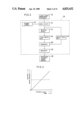
- FIG. 1 is a block diagram and schematic view of a high density spiral track-forming apparatus embodying the present invention
- FIG. 2 is a block diagram of a velocity computing element in the control section of the spiral track-forming apparatus shown in FIG. 1;
- FIG. 3 is a graph showing the change in feed velocity versus the distance moved by the optical recording system, and the change in distance moved by the optical recording system versus time;
- FIG. 4 is a block diagram of the control section of another embodiment of the high density spiral track-forming apparatus according to the present invention.
- FIG. 5A through 5C is a time chart of the control section shown in FIG. 4;
- FIG. 6 is a graph showing the change in feed velocity versus the distance moved by the optical recording system, and the change in distance moved by the optical recording system versus time;
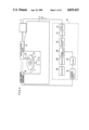
- FIG. 7 is a plan view showing the concrete mechanism of the high density spiral track-forming apparatus shown in FIG. 1.
- FIG. 8 is an elevational view of the high density spiral track-forming apparatus shown in FIG. 7;
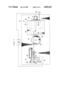
- FIG. 9 is a plan view of the feed mechanism of the optical recording system of the high density spiral track-forming apparatus shown in FIG. 7;
- FIG. 10 is an elevational view of the feed mechanism of the optical recording system shown in FIG. 9;
- FIG. 11 is a cross sectional view of the feed mechanism of the optical recording system shown in FIG. 9;
- FIG. 12 is a cross sectional view, looking from the front, of the feed mechanism of the optical recording system shown in FIG. 9;
- FIG. 13 is an explanatory drawing showing the measurement principles of a laser length measuring instrument of the spiral track-forming apparatus shown in FIG. 1
- FIG. 1 there is shown a high density spiral track-forming apparatus embodying to the present invention identified with the reference number 10, and this spiral track-forming apparatus 10 has an antivibration base 12.
- an optical recording system 14 Provided on the antivibration base 12 are an optical recording system 14, a linear DC feed motor 16, a laser length measuring instrument 18, and a motor 22 which turns a disk-shaped glass substrate disk 20.
- the optical recording system 14 forms a recording track R on a disk-shaped glass substrate disk 20 by means of a light beam L, and is supported, for example, in a floating non-contact manner by an air bearing 24.
- the optical recording-system 14 can move on the surface of the disk 20 by means of the linear DC feed motor 16 in the horizontal direction in the drawing, that is, in the radial feed direction of the disk 20.
- the linear DC feed motor 16 is made up of a motor body 16a, formed from a magnetic yolk with a magnetic gap, and a movable coil 16b which opposes the motor body 16a.
- the motor body 16a is secured-to the antivibration base 12, and the movable coil 16b is linked to the optical recording system 14.
- the motor body 16a and the movable coil 16b do not contact each other. There this motor 16 has high precision of the degree relying on the current flowing in the movable coil 16b. This current is determined by a recording control section 26, which will be described later.
- the laser length measuring instrument 18 measures distance by using laser interference and, as will be later described in more detail, comprises of a laser head, an interferometer, and a reflecting mirror.
- a reflecting mirror is attached to the optical recording system 14 for moving therewith, and it becomes possible to measure the distance moved by the optical recording system 14 relative to the disk 20 by means of the laser length measuring instrument 18. The result of this length measurement is put out to the recording control section 26.
- the measurement resolution of the laser length measuring instrument 18 can be less than 1/100 of the wave length of the laser used.
- the recording control section 26 is added to process the measured results from the laser length measuring instrument 18, and put out the control current to the movable coil 16b, for controlling the velocity at the laser length measuring instrument 18 to the preset target velocity, resulting in forming a predetermined recording track pitch.
- the recording control section 26 includes a velocity computing section 28, a differential amplifier 30, a target velocity output section 32, a controller 34, an amplifier 36, and a controlled variable output section 38.
- the velocity computing section 28 computes the velocity of the movement of the optical recording system 14 from the measured output of the laser length measurement 18.
- the differential amplifier 30 calculates the difference between this computed velocity and the target velocity from the target velocity output section 32, which is previously set according to the track pitch which is to be formed.
- the controlled variable output section 38 comprises, for example, a display section of the result calculated by the velocity computing section 28.
- the velocity computing section 28 is shown in detail in FIG. 2, and comprises a trigger circuit 40, a gate circuit 42, a delaying device 44, a first memory unit 46 and a second memory unit 48, a comparator 50, and a multiplier 52.
- the operation is as follows.
- the gate circuit 42 puts in a position signal from the laser length measuring instrument 18 for the optical recording system 14, in a fixed sampling cycle, of a sampling signal put out from the trigger circuit 40.
- the positional signal is stored in the first memory unit 46 through the delaying device 44 which retards the abovementioned sampling time. Also the positional signal is stored in the second memory unit 48.
- the signals from both memory units 46 and 48 are compared in the comparator 50 and the difference is calculated.
- This difference corresponds to the distance moved by the optical recording system 14 during one sampling period.
- the multiplier 52 multiplies this movement difference by a factor of 1 divided by the sampling time. In other words, by dividing this movement distance by the samling time, it calculates the moving velocity of the optical recording system 14.
- the precision and resolution of the calculated moving velocity is determined by the comparison of the measured resolution of the laser length measuring instrument and the sampling time. For this reason, the precision and the resolution of the calculated moving velocity may exceed the limits of the measured resolution of the laser length measuring instrument 18 and by shortening the sampling period it can be upgraded without any limit, in principle.
- the radial feed velocity of the optical recording system 14 can be controlled with high resolution and precision, and, as a result, a high precision recording track can be accurately formed.
- the disk 20 rotates with a fixed velocity in the direction of the arrow Z in FIG. 1, so that the feed velocity of the optical recording system 14 is determined by the side of the disk 20 and the pitch of the track which is to be formed.
- the recording control section 26 puts out a control current to the moving coil 16b for providing that feed velocity to initiate the radial feed of the optical recording system 14.
- the recording control section 26, at a predetermined sampling period puts in the detected result provided by the laser length measuring instrument 18 according the distance which the optical recording system 14 moves. Based on this distance moved, the moving velocity of the optical recording system 14 is calculated with high resolution, and the difference between this calculated velocity and the predetermined feed velocity is calculated.
- the recording control section 26 then adjusts the control current sent to the moving coil 16b so that this velocity difference becomes zero. Accordingly, the radial feed velocity of the optical recording system 14 is controlled so as to always be equivalent to the fixed predetermined velocity.
- the velocity change relative to the distance moved by the optical recording system 14 is constant, similar to the broken line shown in FIG. 3, making it possible to create a smooth recording track.
- FIG. 4 there is shown another embodiment of the high density spiral track-forming apparatus according to the present invention with the reference number 60.
- a control section 62 of this embodiment is adapted for controlling the feed motor 17 to maintain the moving velocity of the optical recording system 14 in the radial direction of the disk 20 equivalent to the predetermined velocity according to a pulse signal from the laser length measuring instrument 18.
- This control section 62 as shown in FIG. 4, comprises an oscillator 64, a divider 66, a phase comparator 68, a low pass filter 70, a digital/analogue converter 72, an amplifier 74, a frequency detector 76, and a divider 78.
- a pulse which is put out at a fixed period from the oscillator 64 is divided into a standard pulse having a period corresponding to the previously mentioned predetermined velocity, by means of the divider 66, and is fed into one of the input terminals of the phase comparator 68.
- the frequency of the pulse corresponding to the distance moved by the optical recording system 14, which distance is put out by the laser length measurement instrument 18, is detected in the frequency detector device 76, and furthermore the divider 78 divides that pulse, and feeds it to the other input terminal of the phase comparator 68.
- These two input pulses are compared in the phase comparator 68, and the phase difference signal is put out to the amplifier 74 through the low pass filter 70 and the D/A converter 72.
- the amplifier 74 amplifies and arranges the phase difference signal such that the phase difference detected by the phase comparator 68 is reduced to zero, and puts out to the feed motor 17 for controlling the drive of the feed motor 17. Accordingly, in this control section 62, as shown in the timing charts of FIG. 5A to FIG. 5C, the standard pulse (FIG. 5B) with the period a ⁇ t2 corresponds to the predetermined travel speed of the optical recording system 14. And the phase difference ⁇ t3 between the measured pulse (FIG. 5A) of the travel period ⁇ t1 corresponding to the measured result of the travel distance of the optical recording system 14, input from the laser length measuring instrument 18, and the standard pulse ⁇ t2 is detected.
- the drive of the feed motor 17 is controlled to eliminate this phase difference ⁇ t3 thereby maintaining the travel velocity of the optical recording system 14 at the set velocity.
- the regulation control time of the travel velocity of the optical recording system 14 corresponds to the time interval of the pulse train. For this reason, it is possible to expand the servo band to the high frequency band, and thus minimize the track pitch error attributable to the disturbance of the high frequency band.
- the disk 20 rotates with a fixed velocity.
- the feed velocity of the optical recording system 14 is determined by the size of the disk 20 and the pitch of the track which is to be formed.
- the control section 62 puts out a drive signal to the feed motor 17 to provide that feed velocity, and initiates the radial feed of the optical recording system 14.
- the control section 62 puts in the measured result of the travel distance of the optical recording system 14 from the laser length measuring instrument 18, and, based on the pulse train which is this measured result, compares the travel frequency of the optical recording system 14 with the standard pulse train corresponding to the predetermined feed velocity, and calculates the phase difference.
- control section 62 operating to make this phase difference zero and thus controlling the drive of the feed motor 17, controls the velocity by making the radial feed velocity of the optical recording system 14 equivalent to the uniform predetermined feed velocity.
- the change in velocity relative to the travel distance of the optical recording system 14 is uniform, as shown by the broken line in FIG. 6.
- the change in travel distance of the optical recording system 14 relative to time becomes almost a proportional straight line, as shown by the full line in FIG. 6, making it possible to create a smooth recording track.
- FIGS. 7 to 13 a concrete construction is shown for the travel mechanism of the optical recording system, the feed motor, and the laser length measuring instrument.
- the high density spiral track-forming apparatus 10 and 60 comprises a mounting plate 80 for mounting the disk 20 which is mounted on the antivibration plate 12 having a vibration-damping mechanism, the optical recording system 14 which moves in a straight line in the radial direction of the disk 20 for forming a latent image recording track on that glass substrate disk 20, and records an audio signal and a video signal, and the laser length measuring instrument 18 which detects the travel length of the optical recording system 14.
- the mounting plate 80 has a built-in motor, and, the disk 20 is engaged with the rotary shaft of the motor to create an integral unit. Accordingly, the disk 20 which is mounted on the mounting plate 80 rotates along with, and driven by, the rotation of the motor.
- the optical recording system 14 is adapted to form the latent image of a recording track on the disk 20, and includes an optical recording section 82 which records a video signal and an audio signal, and a travel control section 84 which causes the optical recording section 82 to move in a straight line in the radial direction of the disk 20.
- the optical recording section 82 includes internal optics which generates a recording beam for recording data on the disk 20, and in addition includes an object lens 86 which focuses the recording beam on the disk 20, and a reflecting mirror 88 which forms a part of the laser length measuring instrument 18, which will be described later.
- the travel control section 84 includes the feed motor 17 which is controlled by means of the above mentioned control sections 26 and 62, a rail 90 which is connected to the feed motor 17, a slider 92 which adheres to the optical recording section 82 so as to enclose one part of the rail 90, a feed screw 94 which is secured to rotor shaft of the feed motor 17, and a feed nut 96 which secures the slider 92 into which the feed screw 94 is inserted at the center of mass of the optical recording system 82.
- the slider 92 is formed to contain an air channel 98 as shown n FIG. 12; and air fed from an air pump 100 causes it to float relative to the rail 90 without making contact. In other words, the rail 90 and the slider 92 together form an air bearing 102.
- the feed screw 94 rotates, upon which the feed nut 96 moves in a straight line in the radial direction of the disk 20.
- the optical recording section 82 which is fastened to the feed nut 96 through the slider 92, is able to move smoothly in a straight line in the radial direction of the disk 20 because the slider 92 floats without contact on the rail 90.
- the laser length measuring instrument 18 measures distances using a laser beam interference phenomenon, and comprises a laser head 104, a reflecting mirror 106 and a reflecting mirror 108 for altering the beam path, a laser beam splitting section 110, an interferometer 112, a reflecting mirror 88 which is mounted on the optical recording section 82, a beam detecting section 114, and a pulse converter 116.
- the laser head 104 is of a type known as a double frequency laser head, which generates a laser beam having frequencies slightly changed, mutually reverse rotation bilateral polarized light of frequencies f 1 and f 2 .
- the laser beam splitting section 110 includes a standard beam splitter 118 for splitting a laser beam which has had its beam path altered, a photodetector 120 which converts the split laser beam into an electrical signal, and an AC amplifier 122 which amplifies, the photoelectric transferred signal.
- the interferometer 112 puts out the laser beam with the frequency f 1 to the measuring reflecting mirror 88, and the laser beam with the frequency f 2 to a built-in, fixed standard corner cube mirror 124 among the laser beams passing through the laser beam splitting section.
- the interferometer 112 has a measurement beam spliter 126 which photoelectrically registers both laser beams which are then spectrally separated and the beam splitter 126 further receives, the laser both laser beams which are then reflected from the measuring reflecting mirror laser beams reflected from the fixed standard corner cube mirror 124.
- the beam detection section 114 receives the laser beams put from the interferometer 112, and includes a photodetector 128, which photoelectrically converts these laser beams, and an AC amplifier 130 which amplifies the photoelectrically converted signals.
- the pulse converter 116 provides the measured result of the travel distance of the optical recording system 14, based on the signal from the AC amplifier 122 in the laser beam splitting section 110 and the signal from the AC amplifier 130 in the beam detecting section 114.
- FIG. 13 is an explanatory drawing showing the measurement principles of this instrument.
- the laser beams with the frequencies f 1 and f 2 from the laser head. 104 are split in a standard beam splitter 118. One part is directed to a photodetector 120 as a reference signal, while the other part is directed to the interferometer 112 to detect the travel velocity of the optical recording section 82.
- the laser beams detected in the photodetector 120 are amplified in the AC amplifier 122 after being converted photoelectrically and fed to the pulse converter 116.
- the laser beams with the frequencies f 1 and f 2 which pass through the laser beam splitter section 110, are optically separated into their spectral components in the measuring beam splitter 126.
- the laser beam with the frequency f 1 is transmitted to the measuring reflecting mirror 88 which is fixed in the optical recording section 82.
- the laser beam with the frequency f 2 is transmitted by reflection to the fixed standard corner cube mirror 124, and is united with the laser beam with the frequency f 1 , which is reflected back from the measuring reflecting mirror 88, at the measuring beam splitter 126.
- This superpositioning produces an interfering signal.
- the laser beam with the frequency f 1 produces a Doppler modulation of frequency f 1 in the direction of motion and its frequency becomes (f 1 + ⁇ f 1 ).
- the superpositioned laser beams at the measuring beam splitter 126 are put in to the beam detection section 114. And at the photodetector 128, after being converted photoelectrically, the laser beams are amplified in the AC amplifier 130 and put out to the pulse converter 116.
- the pulse converter 116 isolates frequency f 1 from signals from the amplifiers 122 and 130, and puts out one pulse for each 1/4 wave length movement. Namely, within the pulse converter 116, one signal (f 2 -f 1 ) and other signal (f 2 -(f 1 +/-f 1 )) are compared periodically, and, every time one signal is advanced or retarded in relation to the other signal, an up-pulse or down-pulse is put out. This pulse signal is put out to the control sections 26 and 62, and is used for the drive control of the feed motor 17. Furthermore, one pulse can be less than 1/100 of a wave length.
- the first embodiment uses a linear DC motor as the motive means, while the second embodiment uses a standard motor.
- a standard motor could be used in the first embodiment and a linear DC motor in the second embodiment.
Abstract
A high density spiral track forming apparatus according to the present invention a linear motion mechanism for moving an optical recording system in a radial direction of a disk-shaped substrate, and a length measurement machine for detecting the distance travelled by the optical recording system in the radial direction of the substrate disk. The apparatus further includes a velocity computing device for detecting the travel velocity of the optical recording system according to the detected result of the length measurement instrument, and a velocity control device which detects the difference between the travel velocity of the optical recording system which is detected by the velocity computing device and a predetermined velocity, and controls the linear motion mechanism so as to eliminate that difference.
Description
This application is a divisional of application Ser. No. 654,232, filed Sept. 25, 1984, now U.S. Pat. No. 4,730,298.
1. Field of the Invention
The present invention relates to a spiral track-forming apparatus, for forming spiral-shaped recording tracks by feeding an optical recording system in a radial direction of a disk-shaped substance, and more particularly to a spiral track-forming apparatus which can form recording tracks of high density.
2. Description of the Prior Art
Generally, optical track-forming apparatus are known to use the method by which spiral-shaped recording tracks are formed in a photoresist coating on a disk-shaped substrate made from glass. These disks rotate at a fixed angular velocity, and an optical recording system moves in a straight line with a fixed velocity in the radial direction on the substrate disk. In the spiral track-forming apparatus described above, in order to move the optical recording system in the radial direction, a positioning control system is used. With this positioning control system, the optical recording system is moved step-wise in accordance with a pulse signal from a length measuring instrument for detecting the position of the optical recording system. For this reason, the position of the recording track on the glass substrate disk is altered in a step-wise form corresponding to the step-wise movement of the optical recording system.
In recent years, there has been a need for optical recording in a high density mode on glass substrate disk, and a means for making narrower the spacing between the recording tracks (track pitch) is usually considered. There, as a positioning control system, a system having a high resolution of positioning is required. In other words, it is necessary to have a high resolution device as a length measuring instrument for position detection for control of the positioning. However, there are limits to converting a length measuring instrument to high resolution to conform to the reduction (shrinking) of the pitch, and it is not practical. In addition, as described previously, in the case of using a positioning control system, the position of the recorded track does not change smoothly, but rather in a step-wise manner, therefore, if the track pitch is narrowed, adjacent tracks are easily caused to cross. This fact, in the case where the track pitch is narrowed and a high densification of the recording is produced, means that it is very difficult to control the radial feed of the optical recording system with the abovementioned conventional positioning control method. And if this system is executed, track pitch error is produced, and a true recording is not possible.
An object of the present invention is to provide a high density spiral track-forming apparatus which is capable of accurately recording a signal with high density.
Another object of the present invention is to provide a high density spiral track-forming apparatus which is capable of precisely compressing the pitch of the recording track.
Another object of the present invention is to provide a high density spiral track-forming apparatus which is capable of forming a smooth, non-stepwise, spiral-shaped track.
Another object of the present invention is to provide a high density spiral track-forming apparatus which is capable of avoiding track pitch error when forming the high density tracks.
Another object of the present invention is to provide a high density spiral track-forming apparatus which is capable of enlarging the control band of the radial feed of the optical recording system.
In order to achieve the above objectives by means of the present invention, an optical recording system is caused to move in a straight line in the radial direction of a disk-shaped substrate which rotates at a fixed angular velocity. The spiral track-forming apparatus for forming a spiral-shaped recording track on a glass substrate disk which includes a linear electrical motor mechanism which moves the optical recording system in the radial direction of the said glass substrate disk, a length measuring instrument which measures the distance moved in the radial direction by the optical recording system on the said substrate disk, a velocity calculating means which calculates the velocity of the optical recording system based on the measured output of the length measuring instrument, and a velocity control means which detects the difference between the calculated result and the predetermined velocity and controls the drive of the liner electrical motor to eliminate that difference.
BRIEF DESCRIPTION OF THE DRAWINGS
These and other objects, features and advantages of the present invention will become more apparent from the following description of a preferred embodiment taken in conjunction with the accompanying drawings, in which:
FIG. 1 is a block diagram and schematic view of a high density spiral track-forming apparatus embodying the present invention;
FIG. 2 is a block diagram of a velocity computing element in the control section of the spiral track-forming apparatus shown in FIG. 1;
FIG. 3 is a graph showing the change in feed velocity versus the distance moved by the optical recording system, and the change in distance moved by the optical recording system versus time;
FIG. 4 is a block diagram of the control section of another embodiment of the high density spiral track-forming apparatus according to the present invention;
FIG. 5A through 5C is a time chart of the control section shown in FIG. 4;
FIG. 6 is a graph showing the change in feed velocity versus the distance moved by the optical recording system, and the change in distance moved by the optical recording system versus time;
FIG. 7 is a plan view showing the concrete mechanism of the high density spiral track-forming apparatus shown in FIG. 1.
FIG. 8 is an elevational view of the high density spiral track-forming apparatus shown in FIG. 7;
FIG. 9 is a plan view of the feed mechanism of the optical recording system of the high density spiral track-forming apparatus shown in FIG. 7;
FIG. 10 is an elevational view of the feed mechanism of the optical recording system shown in FIG. 9;
FIG. 11 is a cross sectional view of the feed mechanism of the optical recording system shown in FIG. 9;
FIG. 12 is a cross sectional view, looking from the front, of the feed mechanism of the optical recording system shown in FIG. 9;
FIG. 13 is an explanatory drawing showing the measurement principles of a laser length measuring instrument of the spiral track-forming apparatus shown in FIG. 1
Referring now to FIG. 1, there is shown a high density spiral track-forming apparatus embodying to the present invention identified with the reference number 10, and this spiral track-forming apparatus 10 has an antivibration base 12.
Provided on the antivibration base 12 are an optical recording system 14, a linear DC feed motor 16, a laser length measuring instrument 18, and a motor 22 which turns a disk-shaped glass substrate disk 20.
The optical recording system 14 forms a recording track R on a disk-shaped glass substrate disk 20 by means of a light beam L, and is supported, for example, in a floating non-contact manner by an air bearing 24. Thus the optical recording-system 14 can move on the surface of the disk 20 by means of the linear DC feed motor 16 in the horizontal direction in the drawing, that is, in the radial feed direction of the disk 20.
The linear DC feed motor 16 is made up of a motor body 16a, formed from a magnetic yolk with a magnetic gap, and a movable coil 16b which opposes the motor body 16a. The motor body 16a is secured-to the antivibration base 12, and the movable coil 16b is linked to the optical recording system 14. In the linear DC feed motor 16, the motor body 16a and the movable coil 16b do not contact each other. There this motor 16 has high precision of the degree relying on the current flowing in the movable coil 16b. This current is determined by a recording control section 26, which will be described later.
The laser length measuring instrument 18 measures distance by using laser interference and, as will be later described in more detail, comprises of a laser head, an interferometer, and a reflecting mirror. In this embodiment, a reflecting mirror is attached to the optical recording system 14 for moving therewith, and it becomes possible to measure the distance moved by the optical recording system 14 relative to the disk 20 by means of the laser length measuring instrument 18. The result of this length measurement is put out to the recording control section 26. The measurement resolution of the laser length measuring instrument 18 can be less than 1/100 of the wave length of the laser used.
The recording control section 26 is added to process the measured results from the laser length measuring instrument 18, and put out the control current to the movable coil 16b, for controlling the velocity at the laser length measuring instrument 18 to the preset target velocity, resulting in forming a predetermined recording track pitch. The recording control section 26 includes a velocity computing section 28, a differential amplifier 30, a target velocity output section 32, a controller 34, an amplifier 36, and a controlled variable output section 38. The velocity computing section 28 computes the velocity of the movement of the optical recording system 14 from the measured output of the laser length measurement 18. The differential amplifier 30 calculates the difference between this computed velocity and the target velocity from the target velocity output section 32, which is previously set according to the track pitch which is to be formed. According to the calculated velocity difference, a controller 34 and amplifier 36 put out the control current to, the movable coil 16b so that the abovementioned velocity difference becomes zero. Therefore, the motion velocity of the optical recording system is adjusted to the target velocity. Furthermore, the controlled variable output section 38 comprises, for example, a display section of the result calculated by the velocity computing section 28.
The velocity computing section 28 is shown in detail in FIG. 2, and comprises a trigger circuit 40, a gate circuit 42, a delaying device 44, a first memory unit 46 and a second memory unit 48, a comparator 50, and a multiplier 52. The operation is as follows. The gate circuit 42 puts in a position signal from the laser length measuring instrument 18 for the optical recording system 14, in a fixed sampling cycle, of a sampling signal put out from the trigger circuit 40. The positional signal is stored in the first memory unit 46 through the delaying device 44 which retards the abovementioned sampling time. Also the positional signal is stored in the second memory unit 48. The signals from both memory units 46 and 48 are compared in the comparator 50 and the difference is calculated. This difference corresponds to the distance moved by the optical recording system 14 during one sampling period. The multiplier 52 multiplies this movement difference by a factor of 1 divided by the sampling time. In other words, by dividing this movement distance by the samling time, it calculates the moving velocity of the optical recording system 14. In this case, the precision and resolution of the calculated moving velocity is determined by the comparison of the measured resolution of the laser length measuring instrument and the sampling time. For this reason, the precision and the resolution of the calculated moving velocity may exceed the limits of the measured resolution of the laser length measuring instrument 18 and by shortening the sampling period it can be upgraded without any limit, in principle. By this fact, the radial feed velocity of the optical recording system 14 can be controlled with high resolution and precision, and, as a result, a high precision recording track can be accurately formed.
Next, the operation of this embodiment of the present invention will be explained.
The disk 20 rotates with a fixed velocity in the direction of the arrow Z in FIG. 1, so that the feed velocity of the optical recording system 14 is determined by the side of the disk 20 and the pitch of the track which is to be formed. The recording control section 26 puts out a control current to the moving coil 16b for providing that feed velocity to initiate the radial feed of the optical recording system 14. At the same time, the recording control section 26, at a predetermined sampling period, puts in the detected result provided by the laser length measuring instrument 18 according the distance which the optical recording system 14 moves. Based on this distance moved, the moving velocity of the optical recording system 14 is calculated with high resolution, and the difference between this calculated velocity and the predetermined feed velocity is calculated. The recording control section 26 then adjusts the control current sent to the moving coil 16b so that this velocity difference becomes zero. Accordingly, the radial feed velocity of the optical recording system 14 is controlled so as to always be equivalent to the fixed predetermined velocity. By using this type of velocity control system, the velocity change relative to the distance moved by the optical recording system 14 is constant, similar to the broken line shown in FIG. 3, making it possible to create a smooth recording track.
Referring to FIG. 4, there is shown another embodiment of the high density spiral track-forming apparatus according to the present invention with the reference number 60.
In this embodiment, elements which are the same as in FIG. 2 have been given the same reference numbers, and will not be explained further.
A control section 62 of this embodiment is adapted for controlling the feed motor 17 to maintain the moving velocity of the optical recording system 14 in the radial direction of the disk 20 equivalent to the predetermined velocity according to a pulse signal from the laser length measuring instrument 18. This control section 62, as shown in FIG. 4, comprises an oscillator 64, a divider 66, a phase comparator 68, a low pass filter 70, a digital/analogue converter 72, an amplifier 74, a frequency detector 76, and a divider 78. A pulse which is put out at a fixed period from the oscillator 64 is divided into a standard pulse having a period corresponding to the previously mentioned predetermined velocity, by means of the divider 66, and is fed into one of the input terminals of the phase comparator 68. The frequency of the pulse corresponding to the distance moved by the optical recording system 14, which distance is put out by the laser length measurement instrument 18, is detected in the frequency detector device 76, and furthermore the divider 78 divides that pulse, and feeds it to the other input terminal of the phase comparator 68. These two input pulses are compared in the phase comparator 68, and the phase difference signal is put out to the amplifier 74 through the low pass filter 70 and the D/A converter 72. The amplifier 74 amplifies and arranges the phase difference signal such that the phase difference detected by the phase comparator 68 is reduced to zero, and puts out to the feed motor 17 for controlling the drive of the feed motor 17. Accordingly, in this control section 62, as shown in the timing charts of FIG. 5A to FIG. 5C, the standard pulse (FIG. 5B) with the period a Δt2 corresponds to the predetermined travel speed of the optical recording system 14. And the phase difference Δt3 between the measured pulse (FIG. 5A) of the travel period Δt1 corresponding to the measured result of the travel distance of the optical recording system 14, input from the laser length measuring instrument 18, and the standard pulse Δt2 is detected. Then, the drive of the feed motor 17 is controlled to eliminate this phase difference Δt3 thereby maintaining the travel velocity of the optical recording system 14 at the set velocity. By means of the configuration of this type of control section 62, the regulation control time of the travel velocity of the optical recording system 14 corresponds to the time interval of the pulse train. For this reason, it is possible to expand the servo band to the high frequency band, and thus minimize the track pitch error attributable to the disturbance of the high frequency band.
Next, based on this configuration, the operation of the high density spiral track-forming apparatus 60 of this embodiment according to the present invention will be explained.
The disk 20 rotates with a fixed velocity. The feed velocity of the optical recording system 14 is determined by the size of the disk 20 and the pitch of the track which is to be formed. The control section 62 puts out a drive signal to the feed motor 17 to provide that feed velocity, and initiates the radial feed of the optical recording system 14. At the same time, the control section 62 puts in the measured result of the travel distance of the optical recording system 14 from the laser length measuring instrument 18, and, based on the pulse train which is this measured result, compares the travel frequency of the optical recording system 14 with the standard pulse train corresponding to the predetermined feed velocity, and calculates the phase difference. Then the control section 62, operating to make this phase difference zero and thus controlling the drive of the feed motor 17, controls the velocity by making the radial feed velocity of the optical recording system 14 equivalent to the uniform predetermined feed velocity. By using of this kind of velocity control method, the change in velocity relative to the travel distance of the optical recording system 14 is uniform, as shown by the broken line in FIG. 6. In addition, the change in travel distance of the optical recording system 14 relative to time, becomes almost a proportional straight line, as shown by the full line in FIG. 6, making it possible to create a smooth recording track.
Referring to FIGS. 7 to 13, a concrete construction is shown for the travel mechanism of the optical recording system, the feed motor, and the laser length measuring instrument.
As shown in FIGS. 7 and 8, the high density spiral track-forming apparatus 10 and 60 according to the present invention comprises a mounting plate 80 for mounting the disk 20 which is mounted on the antivibration plate 12 having a vibration-damping mechanism, the optical recording system 14 which moves in a straight line in the radial direction of the disk 20 for forming a latent image recording track on that glass substrate disk 20, and records an audio signal and a video signal, and the laser length measuring instrument 18 which detects the travel length of the optical recording system 14.
The mounting plate 80 has a built-in motor, and, the disk 20 is engaged with the rotary shaft of the motor to create an integral unit. Accordingly, the disk 20 which is mounted on the mounting plate 80 rotates along with, and driven by, the rotation of the motor.
The optical recording system 14 is adapted to form the latent image of a recording track on the disk 20, and includes an optical recording section 82 which records a video signal and an audio signal, and a travel control section 84 which causes the optical recording section 82 to move in a straight line in the radial direction of the disk 20. The optical recording section 82 includes internal optics which generates a recording beam for recording data on the disk 20, and in addition includes an object lens 86 which focuses the recording beam on the disk 20, and a reflecting mirror 88 which forms a part of the laser length measuring instrument 18, which will be described later. The travel control section 84 includes the feed motor 17 which is controlled by means of the above mentioned control sections 26 and 62, a rail 90 which is connected to the feed motor 17, a slider 92 which adheres to the optical recording section 82 so as to enclose one part of the rail 90, a feed screw 94 which is secured to rotor shaft of the feed motor 17, and a feed nut 96 which secures the slider 92 into which the feed screw 94 is inserted at the center of mass of the optical recording system 82. The slider 92 is formed to contain an air channel 98 as shown n FIG. 12; and air fed from an air pump 100 causes it to float relative to the rail 90 without making contact. In other words, the rail 90 and the slider 92 together form an air bearing 102. Accordingly, when the feed motor 17 is driven, the feed screw 94 rotates, upon which the feed nut 96 moves in a straight line in the radial direction of the disk 20. At the same time, the optical recording section 82, which is fastened to the feed nut 96 through the slider 92, is able to move smoothly in a straight line in the radial direction of the disk 20 because the slider 92 floats without contact on the rail 90.
By the configuration for the optical recording system 14, as shown in FIG. 10, the line segment 11 joining the respective centers O1 and O2 of the object lens 86 and the feed nut 96 is positioned almost perpendicular to the rotor center line of the disk 20. Accordingly, if a force disturbance Fd is applied, even if the optical recording section 82 undergoes rotary motion around the center O2 of the feed nut 96, the object lens 86 is displaced in almost a vertical direction only, and the displacement component in the direction of the track pitch on the disk 20 can be kept extremely small. In addition, as shown in FIG. 9, the rotary motion of the optical recording section 82 around the center O2 of the feed nut 96 is regulated as a result of the constraints of an air bearing 102, as shown by the arrows f5 to f8, and the component in the radial direction of the disk 20 is extremely small, so that there is the advantage of making it possible to have an extremely small track pitch error as a result of the rotary motion of the optical recording system 14.
As shown in FIG. 7 and FIG. 13, the laser length measuring instrument 18 measures distances using a laser beam interference phenomenon, and comprises a laser head 104, a reflecting mirror 106 and a reflecting mirror 108 for altering the beam path, a laser beam splitting section 110, an interferometer 112, a reflecting mirror 88 which is mounted on the optical recording section 82, a beam detecting section 114, and a pulse converter 116. The laser head 104 is of a type known as a double frequency laser head, which generates a laser beam having frequencies slightly changed, mutually reverse rotation bilateral polarized light of frequencies f1 and f2. And in the output section of this laser beam there is a 1/4 wavelength plate and a 1/2 wavelength plate, and the generated laser beam is put out as linearly polarized light. The reflecting mirrors 106 and 108 are for altering the path of the laser beam which is put out from the laser head 104, directing it in the direction of the measuring reflecting mirror 88. The laser beam splitting section 110 includes a standard beam splitter 118 for splitting a laser beam which has had its beam path altered, a photodetector 120 which converts the split laser beam into an electrical signal, and an AC amplifier 122 which amplifies, the photoelectric transferred signal. The interferometer 112 puts out the laser beam with the frequency f1 to the measuring reflecting mirror 88, and the laser beam with the frequency f2 to a built-in, fixed standard corner cube mirror 124 among the laser beams passing through the laser beam splitting section. In addition, the interferometer 112 has a measurement beam spliter 126 which photoelectrically registers both laser beams which are then spectrally separated and the beam splitter 126 further receives, the laser both laser beams which are then reflected from the measuring reflecting mirror laser beams reflected from the fixed standard corner cube mirror 124. The beam detection section 114 receives the laser beams put from the interferometer 112, and includes a photodetector 128, which photoelectrically converts these laser beams, and an AC amplifier 130 which amplifies the photoelectrically converted signals. The pulse converter 116 provides the measured result of the travel distance of the optical recording system 14, based on the signal from the AC amplifier 122 in the laser beam splitting section 110 and the signal from the AC amplifier 130 in the beam detecting section 114.
Here, the operating principles of the laser length measuring instrument 18 will be explained with reference to FIG. 13 which is an explanatory drawing showing the measurement principles of this instrument.
The laser beams with the frequencies f1 and f2 from the laser head. 104 are split in a standard beam splitter 118. One part is directed to a photodetector 120 as a reference signal, while the other part is directed to the interferometer 112 to detect the travel velocity of the optical recording section 82. The laser beams detected in the photodetector 120 are amplified in the AC amplifier 122 after being converted photoelectrically and fed to the pulse converter 116. The laser beams with the frequencies f1 and f2, which pass through the laser beam splitter section 110, are optically separated into their spectral components in the measuring beam splitter 126. The laser beam with the frequency f1 is transmitted to the measuring reflecting mirror 88 which is fixed in the optical recording section 82. The laser beam with the frequency f2 is transmitted by reflection to the fixed standard corner cube mirror 124, and is united with the laser beam with the frequency f1, which is reflected back from the measuring reflecting mirror 88, at the measuring beam splitter 126. This superpositioning produces an interfering signal. In other words, when the optical recording section 82 moves, the laser beam with the frequency f1 produces a Doppler modulation of frequency f1 in the direction of motion and its frequency becomes (f1 +Δf1). The superpositioned laser beams at the measuring beam splitter 126 are put in to the beam detection section 114. And at the photodetector 128, after being converted photoelectrically, the laser beams are amplified in the AC amplifier 130 and put out to the pulse converter 116. The pulse converter 116 isolates frequency f1 from signals from the amplifiers 122 and 130, and puts out one pulse for each 1/4 wave length movement. Namely, within the pulse converter 116, one signal (f2 -f1) and other signal (f2 -(f1 +/-f1)) are compared periodically, and, every time one signal is advanced or retarded in relation to the other signal, an up-pulse or down-pulse is put out. This pulse signal is put out to the control sections 26 and 62, and is used for the drive control of the feed motor 17. Furthermore, one pulse can be less than 1/100 of a wave length.
In the two embodiments of the present invention discussed above, the first embodiment uses a linear DC motor as the motive means, while the second embodiment uses a standard motor. However, it is obvious that a standard motor could be used in the first embodiment and a linear DC motor in the second embodiment.
In summary, by means of the present invention, it is possible to carry out high density track formation by means of a velocity control system, in which both a feed motor for radial feed of an optical recording system and a laser length measuring instrument are used; and continuous feed is made possible at the target velocity, with high precision and high resolution, so that the track pitch can be narrowed with precision without causing adjacent tracks to intersect.
Various modifications will become possible for those skilled in the art after receiving the teachings of the present disclosure without departing from the scope thereof.
Claims (2)
1. A spiral track-forming apparatus which forms a spiral-shaped recording track on a disk-shaped substrate disk by linearly moving an optical recording system, including focusing means for focusing a recording beam on the surface of the substrate disk which is rotated at a fixed angular velocity, in the radial direction of the substrate disk, comprising:
(a) a rail;
(b) a slider means mounted on the optical recording system and slidably engaged with the rail via an air bearing;
(c) a linear moving means for moving the optical recording system in the radial direction of the substrate disk along a line which passes through the center of the focusing means of the recording beam and through the center of mass of the body of the optical recording system, and which is perpendicular to the center line of rotation of the substrate disk, wherein said linear moving means comprises a feed screw which is arranged on said line that passes through the center of the focusing means of the recording beam and through the center of mass of the body of the optical recording system and which is perpendicular to the center line of rotation of the substrate disk.
2. The apparatus of claim 1, further comprising a nut member which is mounted on the slider means so as to be located on the line which extends in the travelling direction of the optical recording system and which passes through the center of the optical recording system.
Applications Claiming Priority (2)
| Application Number | Priority Date | Filing Date | Title |
|---|---|---|---|
| JP58-176885 | 1983-09-27 | ||
| JP58176885A JPS6070563A (en) | 1983-09-27 | 1983-09-27 | High density spiral drawing device |
Related Parent Applications (1)
| Application Number | Title | Priority Date | Filing Date |
|---|---|---|---|
| US06/654,232 Division US4730298A (en) | 1983-09-27 | 1984-09-25 | Moving device for an optical recording system in a high density spiral track-forming apparatus |
Publications (1)
| Publication Number | Publication Date |
|---|---|
| US4825432A true US4825432A (en) | 1989-04-25 |
Family
ID=16021462
Family Applications (3)
| Application Number | Title | Priority Date | Filing Date |
|---|---|---|---|
| US06/654,232 Expired - Lifetime US4730298A (en) | 1983-09-27 | 1984-09-25 | Moving device for an optical recording system in a high density spiral track-forming apparatus |
| US07/164,471 Expired - Lifetime US4825432A (en) | 1983-09-27 | 1988-03-04 | Frictionless moving device for an optical recording system in a high density spiral track-forming apparatus capable of resisting disturbing forces |
| US07/164,502 Expired - Lifetime US4849955A (en) | 1983-09-27 | 1988-03-04 | Moving device for an optical recording system in a high density spiral track-forming apparatus |
Family Applications Before (1)
| Application Number | Title | Priority Date | Filing Date |
|---|---|---|---|
| US06/654,232 Expired - Lifetime US4730298A (en) | 1983-09-27 | 1984-09-25 | Moving device for an optical recording system in a high density spiral track-forming apparatus |
Family Applications After (1)
| Application Number | Title | Priority Date | Filing Date |
|---|---|---|---|
| US07/164,502 Expired - Lifetime US4849955A (en) | 1983-09-27 | 1988-03-04 | Moving device for an optical recording system in a high density spiral track-forming apparatus |
Country Status (2)
| Country | Link |
|---|---|
| US (3) | US4730298A (en) |
| JP (1) | JPS6070563A (en) |
Cited By (12)
| Publication number | Priority date | Publication date | Assignee | Title |
|---|---|---|---|---|
| US4955011A (en) * | 1986-04-10 | 1990-09-04 | Canon Kabushiki Kaisha | Information recording/reproducing apparatus with control device for maintaining head velocity below a critical velocity |
| US5130972A (en) * | 1989-07-06 | 1992-07-14 | Matsushita Electric Industrial Co., Ltd. | Optical recording and reproducing apparatus |
| US5175723A (en) * | 1990-06-20 | 1992-12-29 | Avnet, Inc. | Direct drive mechanism for data pickup carriage with no direct attachment between motor and frame |
| US5191575A (en) * | 1989-03-06 | 1993-03-02 | Tanashin Denki Co., Ltd. | Plate spring and nut interconnecting for use in an optical pick-up moving apparatus |
| US5517483A (en) * | 1993-06-30 | 1996-05-14 | Daewoo Electronics Co., Ltd. | Gear assembly for transporting a rotation force of a motor shaft to a lead screw |
| US5878015A (en) | 1995-01-25 | 1999-03-02 | Discovision Associates | Laser driver for controlling electrical current passed to a laser in an optical disc system |
| US5974007A (en) | 1995-01-25 | 1999-10-26 | Discovision Associates | Apparatus for moving a carriage assembly from an initial position to a target position |
| US6069857A (en) | 1991-02-15 | 2000-05-30 | Discovision Associates | Optical disc system having improved circuitry for performing blank sector check on readable disc |
| US6141300A (en) | 1989-06-20 | 2000-10-31 | Discovision Associates | Optical actuator including lens assembly with optical axis having symmetric suspensory forces acting thereon and optical disc system including same |
| US6236625B1 (en) | 1991-02-15 | 2001-05-22 | Discovision Associates | Optical disc system having current monitoring circuit with controller for laser driver and method for operating same |
| US6434087B1 (en) | 1995-01-25 | 2002-08-13 | Discovision Associates | Optical disc system and method for controlling bias coil and light source to process information on a storage medium |
| US6532199B1 (en) | 1991-02-15 | 2003-03-11 | Discovision Associates | Optical actuator assembly with lens position sensor for recording or playback |
Families Citing this family (7)
| Publication number | Priority date | Publication date | Assignee | Title |
|---|---|---|---|---|
| US5073881A (en) * | 1987-06-24 | 1991-12-17 | Matsushita Electric Industrial Co., Ltd. | Optical disc apparatus with rapid and stable accessing capability |
| US5285432A (en) * | 1989-10-31 | 1994-02-08 | Kabushiki Kaisha Toshiba | Track jump control circuit |
| JP2533948B2 (en) * | 1989-11-07 | 1996-09-11 | パイオニア株式会社 | Optical disc master recording device |
| US5149951A (en) * | 1990-03-05 | 1992-09-22 | Minnesota Mining & Manufacturing Company, A Corporation Of Delaware | Apparatus and method for presenting a data card for data transfer with centrifugal flyweight |
| JPH05234286A (en) * | 1991-12-26 | 1993-09-10 | Internatl Business Mach Corp <Ibm> | Actuator controller and method thereof |
| TW583643B (en) * | 2002-06-07 | 2004-04-11 | Benq Corp | Driving method |
| WO2013001805A1 (en) * | 2011-06-29 | 2013-01-03 | 株式会社ニコン | Structured illumination optical system and structured illumination microscope device |
Citations (6)
| Publication number | Priority date | Publication date | Assignee | Title |
|---|---|---|---|---|
| US3969574A (en) * | 1974-02-28 | 1976-07-13 | U.S. Philips Corporation | Tubular player arm for an optical recording and reproducing device with drive coil and tachogenerator coil on other end |
| US4228326A (en) * | 1978-11-16 | 1980-10-14 | Mca Discovision Inc. | System for recording information on a rotatable storage disc, in a substantially uniform recording density |
| JPS58102366A (en) * | 1981-12-14 | 1983-06-17 | Hitachi Ltd | Pickup position display circuit |
| JPS58121140A (en) * | 1982-01-11 | 1983-07-19 | Toshiba Corp | Optical disk recorder |
| US4486870A (en) * | 1981-07-23 | 1984-12-04 | Pettigrew Robert M | Optical data storage |
| US4550347A (en) * | 1982-04-07 | 1985-10-29 | Pioneer Video Corporation | Method for recording information on a recording disc |
Family Cites Families (23)
| Publication number | Priority date | Publication date | Assignee | Title |
|---|---|---|---|---|
| US3716845A (en) * | 1972-03-09 | 1973-02-13 | Honeywell Inc | Optical memory with interferometer tracking |
| GB1396834A (en) * | 1973-01-31 | 1975-06-04 | Ibm | Data storage apparatus |
| GB1499268A (en) * | 1976-06-30 | 1978-01-25 | Ibm | Servo apparatus |
| JPS5936345B2 (en) * | 1977-04-28 | 1984-09-03 | ソニー株式会社 | Linear movement type tone arm device |
| JPS5471612A (en) * | 1977-11-17 | 1979-06-08 | Nec Corp | Servo track writing device of magnetic disc memory device |
| JPS5938668B2 (en) * | 1978-10-02 | 1984-09-18 | 日本電信電話株式会社 | Servo signal writing device |
| US4190860A (en) * | 1978-11-16 | 1980-02-26 | Mca Discovision, Inc. | Digital method and apparatus for rotating an information storage disc |
| US4351044A (en) * | 1979-01-09 | 1982-09-21 | Matsushita Electric Industrial Co., Ltd. | Recording system using disk-shaped recording medium |
| JPS5641537A (en) * | 1979-09-07 | 1981-04-18 | Toshiba Corp | Optical disk control unit |
| JPS5687239A (en) * | 1979-12-18 | 1981-07-15 | Matsushita Electric Ind Co Ltd | Optical recording and reproducing device |
| NL8005258A (en) * | 1980-09-22 | 1982-04-16 | Philips Nv | INTERFEROMETER. |
| JPS57181482A (en) * | 1981-05-01 | 1982-11-08 | Toshiba Corp | Disc device |
| JPS57181436A (en) * | 1981-05-01 | 1982-11-08 | Toshiba Corp | Optical disc device |
| US4443107A (en) * | 1981-08-03 | 1984-04-17 | Alexander David H | Optical displacement sensor |
| KR880000999B1 (en) * | 1981-11-25 | 1988-06-10 | 미쓰다 가쓰시게 | Optical memory apparatus |
| JPS5897160A (en) * | 1981-12-03 | 1983-06-09 | Matsushita Electric Ind Co Ltd | Speed fine adjustment and display device for record disc player |
| JPS5898846A (en) * | 1981-12-07 | 1983-06-11 | Pioneer Video Corp | Recording system for disc-shaped recording medium |
| JPS58137168A (en) * | 1982-02-10 | 1983-08-15 | Hitachi Ltd | Disk device |
| US4519056A (en) * | 1982-03-15 | 1985-05-21 | Tokyo Shibaura Denki Kabushiki Kaisha | Optical disk apparatus |
| JPS58158081A (en) * | 1982-03-15 | 1983-09-20 | Toshiba Corp | Information recording device |
| DE3300369A1 (en) * | 1982-04-05 | 1983-10-06 | Suhl Feinmesszeugfab Veb | STANDING SHAFT INTERFEROMETER FOR MEASURING OPTICAL GEAR DIFFERENCES |
| EP0098076A1 (en) * | 1982-06-14 | 1984-01-11 | Nec Corporation | Beam access apparatus for optical disc system |
| JPS5956262A (en) * | 1982-09-27 | 1984-03-31 | Toshiba Corp | Disc device |
-
1983
- 1983-09-27 JP JP58176885A patent/JPS6070563A/en active Pending
-
1984
- 1984-09-25 US US06/654,232 patent/US4730298A/en not_active Expired - Lifetime
-
1988
- 1988-03-04 US US07/164,471 patent/US4825432A/en not_active Expired - Lifetime
- 1988-03-04 US US07/164,502 patent/US4849955A/en not_active Expired - Lifetime
Patent Citations (6)
| Publication number | Priority date | Publication date | Assignee | Title |
|---|---|---|---|---|
| US3969574A (en) * | 1974-02-28 | 1976-07-13 | U.S. Philips Corporation | Tubular player arm for an optical recording and reproducing device with drive coil and tachogenerator coil on other end |
| US4228326A (en) * | 1978-11-16 | 1980-10-14 | Mca Discovision Inc. | System for recording information on a rotatable storage disc, in a substantially uniform recording density |
| US4486870A (en) * | 1981-07-23 | 1984-12-04 | Pettigrew Robert M | Optical data storage |
| JPS58102366A (en) * | 1981-12-14 | 1983-06-17 | Hitachi Ltd | Pickup position display circuit |
| JPS58121140A (en) * | 1982-01-11 | 1983-07-19 | Toshiba Corp | Optical disk recorder |
| US4550347A (en) * | 1982-04-07 | 1985-10-29 | Pioneer Video Corporation | Method for recording information on a recording disc |
Non-Patent Citations (1)
| Title |
|---|
| K. Sano et al., Television Gakkaishi, vol. 37, No. 6, p. 482 (1983) (with English translation). * |
Cited By (22)
| Publication number | Priority date | Publication date | Assignee | Title |
|---|---|---|---|---|
| US4955011A (en) * | 1986-04-10 | 1990-09-04 | Canon Kabushiki Kaisha | Information recording/reproducing apparatus with control device for maintaining head velocity below a critical velocity |
| US5191575A (en) * | 1989-03-06 | 1993-03-02 | Tanashin Denki Co., Ltd. | Plate spring and nut interconnecting for use in an optical pick-up moving apparatus |
| US6141300A (en) | 1989-06-20 | 2000-10-31 | Discovision Associates | Optical actuator including lens assembly with optical axis having symmetric suspensory forces acting thereon and optical disc system including same |
| US5130972A (en) * | 1989-07-06 | 1992-07-14 | Matsushita Electric Industrial Co., Ltd. | Optical recording and reproducing apparatus |
| US5175723A (en) * | 1990-06-20 | 1992-12-29 | Avnet, Inc. | Direct drive mechanism for data pickup carriage with no direct attachment between motor and frame |
| US6532199B1 (en) | 1991-02-15 | 2003-03-11 | Discovision Associates | Optical actuator assembly with lens position sensor for recording or playback |
| US6236625B1 (en) | 1991-02-15 | 2001-05-22 | Discovision Associates | Optical disc system having current monitoring circuit with controller for laser driver and method for operating same |
| US6122232A (en) * | 1991-02-15 | 2000-09-19 | Discovision Associates | Isolation apparatus for use in disc drive system to mitigate effects of undesired mechanical forces and disc drive system including same |
| US6069857A (en) | 1991-02-15 | 2000-05-30 | Discovision Associates | Optical disc system having improved circuitry for performing blank sector check on readable disc |
| US5517483A (en) * | 1993-06-30 | 1996-05-14 | Daewoo Electronics Co., Ltd. | Gear assembly for transporting a rotation force of a motor shaft to a lead screw |
| US6087644A (en) | 1995-01-25 | 2000-07-11 | Discovision Associates | Focus capture for optical disc system including detection of quad sum signal to close focus |
| US6058081A (en) | 1995-01-25 | 2000-05-02 | Discovision Associates | Optical drive system having servomotor operated relative to maximum quad sum signal |
| US6034364A (en) | 1995-01-25 | 2000-03-07 | Discovision Associates | Optical disc system including focus capture assembly with focus error signal circuit and method for operating same |
| US5974007A (en) | 1995-01-25 | 1999-10-26 | Discovision Associates | Apparatus for moving a carriage assembly from an initial position to a target position |
| US6243336B1 (en) | 1995-01-25 | 2001-06-05 | Discovision Associates | Optical disc system having servo motor and servo error detection assembly operated relative to monitored quad sum signal and focus capture method for use in same |
| US6266306B1 (en) | 1995-01-25 | 2001-07-24 | Discovision Associates | Analog to digital converter and assembly for use in optical drive system to normalize servo error signals and multiplex reference voltage inputs and digital outputs |
| US6278665B1 (en) | 1995-01-25 | 2001-08-21 | Discovision Associates | Optical disc system including current monitoring circuit assembly having controller with improved optics module and laser driver and method for operating same |
| US6317391B1 (en) | 1995-01-25 | 2001-11-13 | Discovision Associates | Optical disc system having current monitoring circuit with improved bias coil assembly and controller for laser driver and method for operating same |
| US6418097B1 (en) | 1995-01-25 | 2002-07-09 | Discovision Associates | Analog to digital converter assembly for normalizing servo error signals and multiplexing reference voltage inputs and digital outputs and improved optical drive system including same |
| US6434087B1 (en) | 1995-01-25 | 2002-08-13 | Discovision Associates | Optical disc system and method for controlling bias coil and light source to process information on a storage medium |
| US5878015A (en) | 1995-01-25 | 1999-03-02 | Discovision Associates | Laser driver for controlling electrical current passed to a laser in an optical disc system |
| US6741529B1 (en) | 1995-01-25 | 2004-05-25 | Discovision Associates | Method and apparatus for moving carriage assembly from initial position to target position and optical disc system including same |
Also Published As
| Publication number | Publication date |
|---|---|
| US4730298A (en) | 1988-03-08 |
| US4849955A (en) | 1989-07-18 |
| JPS6070563A (en) | 1985-04-22 |
Similar Documents
| Publication | Publication Date | Title |
|---|---|---|
| US4825432A (en) | Frictionless moving device for an optical recording system in a high density spiral track-forming apparatus capable of resisting disturbing forces | |
| US4271334A (en) | Apparatus for correcting for temperature-induced tracking errors in a system for recovering information from a recording disc | |
| US4663751A (en) | Optical information processor for compensating offset | |
| US3829622A (en) | Video disc player with variably biased pneumatic head | |
| US3944727A (en) | Video disc player with movable mirror for directing light beam onto reflective disc | |
| US4809247A (en) | Video disc head tracking apparatus | |
| US4168457A (en) | Self adaptive speed control system | |
| US5131744A (en) | Mirror rotation angle detection mechanism | |
| EP0155077B1 (en) | Servo system | |
| JPS6238770B2 (en) | ||
| US4703467A (en) | Video disc read back scanner | |
| JP2749466B2 (en) | Track deviation correction method and apparatus for optical disk drive | |
| JPS6226644A (en) | Optical type information recording and reproducing device | |
| US4745588A (en) | Tracking control apparatus | |
| US3716845A (en) | Optical memory with interferometer tracking | |
| NO141135B (en) | DEVICE FOR READING A PLATE-SHAPED RECORD CARRIER | |
| JPS60209981A (en) | High-density spiral drawing device | |
| US5079432A (en) | Method and apparatus for measuring the displacement of an automatic scan tracking head | |
| US4498110A (en) | Optical disc reproducing apparatus | |
| US5724329A (en) | Apparatus for controlling rotational servo by using frequency pulse signal generator | |
| US4837759A (en) | Optical information recorder | |
| JP2811816B2 (en) | Image rotator servo circuit | |
| US5301173A (en) | Optical recording apparatus with two tracking error signals | |
| US4104573A (en) | Speed control device for a moving member | |
| KR840001863B1 (en) | Video disc player |
Legal Events
| Date | Code | Title | Description |
|---|---|---|---|
| STCF | Information on status: patent grant |
Free format text: PATENTED CASE |
|
| FEPP | Fee payment procedure |
Free format text: PAYOR NUMBER ASSIGNED (ORIGINAL EVENT CODE: ASPN); ENTITY STATUS OF PATENT OWNER: LARGE ENTITY |
|
| FPAY | Fee payment |
Year of fee payment: 4 |
|
| FPAY | Fee payment |
Year of fee payment: 8 |
|
| FPAY | Fee payment |
Year of fee payment: 12 |