US4823984A - Container storage and dispensing apparatus and vending machine for dispensing refrigerated, unrefrigerated and/or heated foods - Google Patents
Container storage and dispensing apparatus and vending machine for dispensing refrigerated, unrefrigerated and/or heated foods Download PDFInfo
- Publication number
- US4823984A US4823984A US07/041,760 US4176087A US4823984A US 4823984 A US4823984 A US 4823984A US 4176087 A US4176087 A US 4176087A US 4823984 A US4823984 A US 4823984A
- Authority
- US
- United States
- Prior art keywords
- dispensing
- storage
- vending machine
- refrigerated
- set forth
- Prior art date
- Legal status (The legal status is an assumption and is not a legal conclusion. Google has not performed a legal analysis and makes no representation as to the accuracy of the status listed.)
- Expired - Lifetime
Links
- 235000013305 food Nutrition 0.000 title claims abstract description 177
- 238000001816 cooling Methods 0.000 claims description 40
- 239000007788 liquid Substances 0.000 claims description 25
- 238000010438 heat treatment Methods 0.000 claims description 18
- 238000002156 mixing Methods 0.000 claims description 16
- 239000006260 foam Substances 0.000 claims description 10
- 238000005057 refrigeration Methods 0.000 claims description 8
- 238000000151 deposition Methods 0.000 claims 8
- XLYOFNOQVPJJNP-UHFFFAOYSA-N water Substances O XLYOFNOQVPJJNP-UHFFFAOYSA-N 0.000 description 12
- 235000009508 confectionery Nutrition 0.000 description 5
- 230000000712 assembly Effects 0.000 description 3
- 238000000429 assembly Methods 0.000 description 3
- 230000037431 insertion Effects 0.000 description 3
- 238000003780 insertion Methods 0.000 description 3
- 239000011810 insulating material Substances 0.000 description 3
- 238000002372 labelling Methods 0.000 description 3
- 235000011888 snacks Nutrition 0.000 description 3
- 238000009413 insulation Methods 0.000 description 2
- 238000003825 pressing Methods 0.000 description 2
- 235000009470 Theobroma cacao Nutrition 0.000 description 1
- 244000240602 cacao Species 0.000 description 1
- 235000020965 cold beverage Nutrition 0.000 description 1
- 238000010276 construction Methods 0.000 description 1
- 235000021268 hot food Nutrition 0.000 description 1
- 239000000463 material Substances 0.000 description 1
- 238000002844 melting Methods 0.000 description 1
- 230000008018 melting Effects 0.000 description 1
- 238000007789 sealing Methods 0.000 description 1
Images


Classifications
-
- G—PHYSICS
- G07—CHECKING-DEVICES
- G07F—COIN-FREED OR LIKE APPARATUS
- G07F17/00—Coin-freed apparatus for hiring articles; Coin-freed facilities or services
- G07F17/0064—Coin-freed apparatus for hiring articles; Coin-freed facilities or services for processing of food articles
- G07F17/0078—Food articles which need to be processed for dispensing in a hot or cooked condition, e.g. popcorn, nuts
-
- F—MECHANICAL ENGINEERING; LIGHTING; HEATING; WEAPONS; BLASTING
- F25—REFRIGERATION OR COOLING; COMBINED HEATING AND REFRIGERATION SYSTEMS; HEAT PUMP SYSTEMS; MANUFACTURE OR STORAGE OF ICE; LIQUEFACTION SOLIDIFICATION OF GASES
- F25D—REFRIGERATORS; COLD ROOMS; ICE-BOXES; COOLING OR FREEZING APPARATUS NOT OTHERWISE PROVIDED FOR
- F25D19/00—Arrangement or mounting of refrigeration units with respect to devices or objects to be refrigerated, e.g. infrared detectors
-
- F—MECHANICAL ENGINEERING; LIGHTING; HEATING; WEAPONS; BLASTING
- F25—REFRIGERATION OR COOLING; COMBINED HEATING AND REFRIGERATION SYSTEMS; HEAT PUMP SYSTEMS; MANUFACTURE OR STORAGE OF ICE; LIQUEFACTION SOLIDIFICATION OF GASES
- F25D—REFRIGERATORS; COLD ROOMS; ICE-BOXES; COOLING OR FREEZING APPARATUS NOT OTHERWISE PROVIDED FOR
- F25D23/00—General constructional features
- F25D23/12—Arrangements of compartments additional to cooling compartments; Combinations of refrigerators with other equipment, e.g. stove
-
- G—PHYSICS
- G07—CHECKING-DEVICES
- G07F—COIN-FREED OR LIKE APPARATUS
- G07F11/00—Coin-freed apparatus for dispensing, or the like, discrete articles
- G07F11/02—Coin-freed apparatus for dispensing, or the like, discrete articles from non-movable magazines
- G07F11/04—Coin-freed apparatus for dispensing, or the like, discrete articles from non-movable magazines in which magazines the articles are stored one vertically above the other
- G07F11/16—Delivery means
- G07F11/24—Rotary or oscillatory members
-
- G—PHYSICS
- G07—CHECKING-DEVICES
- G07F—COIN-FREED OR LIKE APPARATUS
- G07F11/00—Coin-freed apparatus for dispensing, or the like, discrete articles
- G07F11/02—Coin-freed apparatus for dispensing, or the like, discrete articles from non-movable magazines
- G07F11/28—Coin-freed apparatus for dispensing, or the like, discrete articles from non-movable magazines in which the magazines are inclined
-
- G—PHYSICS
- G07—CHECKING-DEVICES
- G07F—COIN-FREED OR LIKE APPARATUS
- G07F11/00—Coin-freed apparatus for dispensing, or the like, discrete articles
- G07F11/02—Coin-freed apparatus for dispensing, or the like, discrete articles from non-movable magazines
- G07F11/38—Coin-freed apparatus for dispensing, or the like, discrete articles from non-movable magazines in which the magazines are horizontal
- G07F11/42—Coin-freed apparatus for dispensing, or the like, discrete articles from non-movable magazines in which the magazines are horizontal the articles being delivered by motor-driven means
-
- G—PHYSICS
- G07—CHECKING-DEVICES
- G07F—COIN-FREED OR LIKE APPARATUS
- G07F17/00—Coin-freed apparatus for hiring articles; Coin-freed facilities or services
- G07F17/0064—Coin-freed apparatus for hiring articles; Coin-freed facilities or services for processing of food articles
- G07F17/0071—Food articles which need to be processed for dispensing in a cold condition, e.g. ice and ice cream
-
- F—MECHANICAL ENGINEERING; LIGHTING; HEATING; WEAPONS; BLASTING
- F25—REFRIGERATION OR COOLING; COMBINED HEATING AND REFRIGERATION SYSTEMS; HEAT PUMP SYSTEMS; MANUFACTURE OR STORAGE OF ICE; LIQUEFACTION SOLIDIFICATION OF GASES
- F25D—REFRIGERATORS; COLD ROOMS; ICE-BOXES; COOLING OR FREEZING APPARATUS NOT OTHERWISE PROVIDED FOR
- F25D17/00—Arrangements for circulating cooling fluids; Arrangements for circulating gas, e.g. air, within refrigerated spaces
- F25D17/04—Arrangements for circulating cooling fluids; Arrangements for circulating gas, e.g. air, within refrigerated spaces for circulating air, e.g. by convection
- F25D17/06—Arrangements for circulating cooling fluids; Arrangements for circulating gas, e.g. air, within refrigerated spaces for circulating air, e.g. by convection by forced circulation
-
- F—MECHANICAL ENGINEERING; LIGHTING; HEATING; WEAPONS; BLASTING
- F25—REFRIGERATION OR COOLING; COMBINED HEATING AND REFRIGERATION SYSTEMS; HEAT PUMP SYSTEMS; MANUFACTURE OR STORAGE OF ICE; LIQUEFACTION SOLIDIFICATION OF GASES
- F25D—REFRIGERATORS; COLD ROOMS; ICE-BOXES; COOLING OR FREEZING APPARATUS NOT OTHERWISE PROVIDED FOR
- F25D2317/00—Details or arrangements for circulating cooling fluids; Details or arrangements for circulating gas, e.g. air, within refrigerated spaces, not provided for in other groups of this subclass
- F25D2317/06—Details or arrangements for circulating cooling fluids; Details or arrangements for circulating gas, e.g. air, within refrigerated spaces, not provided for in other groups of this subclass with forced air circulation
- F25D2317/065—Details or arrangements for circulating cooling fluids; Details or arrangements for circulating gas, e.g. air, within refrigerated spaces, not provided for in other groups of this subclass with forced air circulation characterised by the air return
- F25D2317/0651—Details or arrangements for circulating cooling fluids; Details or arrangements for circulating gas, e.g. air, within refrigerated spaces, not provided for in other groups of this subclass with forced air circulation characterised by the air return through the bottom
-
- F—MECHANICAL ENGINEERING; LIGHTING; HEATING; WEAPONS; BLASTING
- F25—REFRIGERATION OR COOLING; COMBINED HEATING AND REFRIGERATION SYSTEMS; HEAT PUMP SYSTEMS; MANUFACTURE OR STORAGE OF ICE; LIQUEFACTION SOLIDIFICATION OF GASES
- F25D—REFRIGERATORS; COLD ROOMS; ICE-BOXES; COOLING OR FREEZING APPARATUS NOT OTHERWISE PROVIDED FOR
- F25D2317/00—Details or arrangements for circulating cooling fluids; Details or arrangements for circulating gas, e.g. air, within refrigerated spaces, not provided for in other groups of this subclass
- F25D2317/06—Details or arrangements for circulating cooling fluids; Details or arrangements for circulating gas, e.g. air, within refrigerated spaces, not provided for in other groups of this subclass with forced air circulation
- F25D2317/066—Details or arrangements for circulating cooling fluids; Details or arrangements for circulating gas, e.g. air, within refrigerated spaces, not provided for in other groups of this subclass with forced air circulation characterised by the air supply
- F25D2317/0661—Details or arrangements for circulating cooling fluids; Details or arrangements for circulating gas, e.g. air, within refrigerated spaces, not provided for in other groups of this subclass with forced air circulation characterised by the air supply from the bottom
-
- F—MECHANICAL ENGINEERING; LIGHTING; HEATING; WEAPONS; BLASTING
- F25—REFRIGERATION OR COOLING; COMBINED HEATING AND REFRIGERATION SYSTEMS; HEAT PUMP SYSTEMS; MANUFACTURE OR STORAGE OF ICE; LIQUEFACTION SOLIDIFICATION OF GASES
- F25D—REFRIGERATORS; COLD ROOMS; ICE-BOXES; COOLING OR FREEZING APPARATUS NOT OTHERWISE PROVIDED FOR
- F25D25/00—Charging, supporting, and discharging the articles to be cooled
-
- F—MECHANICAL ENGINEERING; LIGHTING; HEATING; WEAPONS; BLASTING
- F25—REFRIGERATION OR COOLING; COMBINED HEATING AND REFRIGERATION SYSTEMS; HEAT PUMP SYSTEMS; MANUFACTURE OR STORAGE OF ICE; LIQUEFACTION SOLIDIFICATION OF GASES
- F25D—REFRIGERATORS; COLD ROOMS; ICE-BOXES; COOLING OR FREEZING APPARATUS NOT OTHERWISE PROVIDED FOR
- F25D31/00—Other cooling or freezing apparatus
- F25D31/005—Combined cooling and heating devices
Definitions
- This invention relates to a container storage and dispensing apparatus and a vending machine for dispensing refrigerated foods, for example drink containers, unrefrigerated foods such as packaged snacks and/or heated foods such as hot coffee.
- vending machines can provide a refrigerated section to keep products cold.
- food vending machines are known for dispensing sandwiches or cold drinks by inserting coins or bills.
- vending machines which dispense products which are not refrigerated.
- candy or snack food packages are generally kept in a non-refrigerated vending machine.
- Vending machines are also available for dispensing heated foods, for example, coffee and cocoa machines dispense heated liquids. Very often it is desired to have both unrefrigerated, refrigerated and heated foods dispensed at the same physical location, such as in an employee kitchen.
- vending machines have refrigerated and unrefrigerated sections or areas, but require all the dispensed products to pass through both the refrigerated and unrefrigerated sections prior to dispensing. In these vending machines it is not possible to independently or separately dispense the product from the refrigerated and unrefrigerated sections. Nor do these vending machines provide for the dispensing of heated product.
- a vending machine permitting the dispensing of refrigerated product and heated product from a single machine; the provision of such a vending machine which will also dispense unrefrigerated product; the provision of such vending machine which is suitable for locations having space limitations; the provision of such vending machine which permits the independent and separate dispensing of refrigerated, unrefrigerated and heated product; the provision of such vending machine which partially cools product in the unrefrigerated section of the vending machine; the provision of such vending machine which has a single selection control for choosing refrigerated, unrefrigerated and/or heated product; the provision of such vending machine which is economically feasible and commercially practical; the provision of an apparatus for storing and dispensing drink containers; the provision of such apparatus to which cooling may be added to provide a refrigerated area; the provision of such apparatus which is suitable for use in existing unrefrigerated vending machines; and the provision of such apparatus which is compact.
- a container storage and dispensing apparatus of the present invention includes housing means for enclosing a storage and dispensing area, the housing means having an access door for inserting the containers and having a first and a second exit door for dispensing the containers.
- the apparatus includes first guide means in the housing means for guiding and supporting a first level of containers away from the access door toward a first intermediate location near the rear of the housing means and second guide means in the housing means for receiving containers from the first guide means at the first intermediate location, for guiding and supporting a second level of containers away from the intermediate location to the first exit door.
- the apparatus further includes third guide means in the housing means for guiding and supporting a third level of containers away from the access door toward a second intermediate location near the rear of the housing means, the third level of containers being positioned below the first level and the second intermediate location being closer the access door than the first intermediate location and fourth guide means in the housing means for receiving containers from the third guide means at the second intermediate location and for guiding and supporting a fourth level of containers away from the intermediate location to the second exit door, the fourth level of containers being positioned above the second level.
- the apparatus includes first and second means respectively associated with the second and fourth levels for selectably dispensing one of the containers from either the second or fourth levels.
- Each dispensing means includes a levered gate movable between an open and a closed position, the levered gate when in the closed position for retaining the container in the storage and dispensing area and when in the open position for dispensing one of the containers through the exit door and for retaining the remaining containers in the storage and dispensing area.
- the dispensing means also includes means for moving the levered gate from the closed position to the open position to dispense one of the containers and to return the gate to the closed position.
- a vending machine of the present invention is for dispensing refrigerated and heated foods.
- the vending machine includes a housing having a refrigerated storage and dispensing area for the refrigerated foods and a heated storage and dispensing area for the heated foods, each area being separate from the other area.
- the vending machine also includes a device contained in the housing for cooling the refrigerated foods in the refrigerated storage and dispensing area.
- the vending machine further includes a device contained in the housing for heating the heated foods in the heated storage and dispensing area.
- the vending machine has a first receiving device adjacent the refrigerated storage and dispensing area for receiving dispensed foods from the refrigerated storage and dispensing area and a second receiving device for receiving the heated food from the heated storage and dispensing area.
- the vending machine also has a common device for selecting one of the refrigerated foods or heated foods to be dispensed to the first or second receiving device, respectively and a device responsive to the selecting means for dispensing the selected food to the first or second receiving device.
- the vending machine includes a housing having a refrigerated storage and dispensing area for the refrigerated foods, an unrefrigerated storage and dispensing area for the unrefrigerated foods and a heated storage and dispensing area for the heated foods, each area being separate from the other areas.
- the vending machine also includes a device contained in the housing means for cooling the refrigerated foods in the refrigerated storage and dispensing area and a device contained in the housing means for heating the heated foods in the heated storage and dispensing area.
- the vending machine further includes a common receiving device adjacent the refrigerated and unrefrigerated storage and dispensing areas for receiving dispensed foods from either the refrigerated or unrefrigerated storage and dispensing area and a separate device for receiving the heated food from the heated storage and dispensing area. Additionally, the vending machine includes a common device for selecting one of the refrigerated foods, unrefrigerated foods or heated foods to be dispensed to the common receiving device or separate receiving device and a device responsive to the selecting device for dispensing the selected food to the common receiving device or separate receiving device.
- FIG. 1 is a front view of the vending machine of the present invention
- FIG. 2 is a perspective view of the vending machine of FIG. 1 with a front door opened;
- FIG. 3 is a side view of the vending machine in FIG. 1 with a portion cutaway showing an interior cross-section including a refreigerated and unrefrigerated area;
- FIG. 3A is a side view of the vending machine with a portion cutaway showing an interior cross-section which includes an alternative preferred embodiment of the refrigerated area;
- FIG. 4 is a close up view of a refrigerated area of the vending machine in FIG. 1 with a portion cutaway;
- FIG. 4A is a close up view of the alternative preferred embodiment of the refrigerated area of the vending machine in FIG. 3A with a portion cutaway;
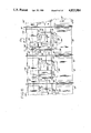
- FIG. 5 is a side view of a drink can dispenser of the vending machine in FIG. 1;
- FIG. 5A is a side view of a drink can dispenser of the vending machine in FIG. 3A;
- FIG. 5B is a side view of the drink can dispenser in FIG. 5 showing a can being dispensed
- FIG. 6 is a view from the line 6--6 in FIG. 5;
- FIG. 7 is a close-up view of a refrigeration unit included in FIG. 3.
- FIG. 8 is a side view of the vending machine in FIG. 1 partially cut away to show a heated area included in the vending machine.
- the vending machine 1 of the present invention has a door 3 having a clear see-thru panel for displaying foods in the vending machine.
- Unrefrigerated foods such as candy or food packages, are displayed in the vending machine 1 in an upper section or unrefrigerated food storage and dispensing area 5.
- refrigerated foods such as drink containers or cans, are displayed in a lower section or refrigerated food storage and dispensing area 7.
- machine 1 includes a display 803 which shows pictures of heated foods stored in a heated storage and dispensing area 805. Area 805 is separated from the areas 5 and 7 by a divider 807.
- a selection panel 9 has a plurality of push button switches 11 corresponding to a respective product in dispensers of the unrefrigerated, refrigerated or heated storage and dispensing areas 5, 7 and 805.
- the selection panel 9 includes a vendor control and selection system as described in U.S. Pat. No. 4,512,453, which is incorporated herein by reference.
- Money is inserted in the selection panel 9 and when a proper amount is inserted, push button switches 11 may be operated.
- refrigerated or unrefrigerated foods are dispensed to a common receiving device or curved shelf 18 which is accessible through an opening 17 in the door 3. Heated foods may also be dispensed in response to a pushed switch 11 to a separate receiving device 811 accessible through an opening 813 in the door 3.
- the door 3 is mounted on an exterior housing 15 and may be opened for access to the vending machine interior which includes the unrefrigerated and refrigerated storage and dispensing areas 5 and 7 and the heated storage and dispensing area 805.
- the housing 15 thus constitutes housing means having a refrigerated storage and dispensing area for the refrigerated foods, an unrefrigerated storage and dispensing area for the unrefrigerated foods and a heated storage and dispensing area for the heated foods, each area being separate from the other area.
- the unrefrigerated storage and dispensing area 5 has four shelves 19a, 19b, 19c and 19d.
- Each of the shelves 19 has separators 23 between spiral arms 25 in which the unrefrigerated foods such as candy bars or snack food packages are placed.
- the spiral arms 25 are rotated by motors (not shown) in response to a machine controller as shown in FIG. 1 of U.S. Pat. No. 4,512,453 for dispensing the unrefrigerated foods.
- a dispenser having spiral arms for dispensing food packages is shown in U.S. Pat. No. 3,986,759, which is incorporated herein by reference.
- the refrigerated storage and dispensing area 7 has a clear continuous exit door 27 masked so that four windows 29a, 29b, 29c and 29d are outlined for displaying the drink can to be next dispensed from one of four corresponding dispensers 31a, 31b, 31c and 31d.
- the dispenser 31b is shown in FIG. 3.
- Labels 33a, 33b, 33c and 33d may be mounted below the corresponding window 29 for displaying such things as price and item number for the corresponding switch on the selection panel 9.
- Additional track labelling 35 may also be attached above the windows 29 to further identify the refrigerated foods, e.g., brand names.
- a door 37 is mounted above the labelling 35 and may also have labels attached thereto.
- Another door 39 is mounted below the windows 29 and provides access to a refrigerated storage area 41.
- the door 37 is attached to a generally rectangularly shaped housing 48 for enclosing the storage and dispensing area 7.
- the door 37 is mounted on a strip hinge 47 with spring 46 which tends to keep the door 37 in a vertical or closed position.
- the spring 46 is an example of spring means tending to keep the door closed.
- Door 37 consists of two pieces of material, an outside piece 49 and an inside piece 51 with an air insulating space therebetween. The door 37 tends to be pressed against gaskets 53 and 55 by the spring 46 to seal the storage and dispensing area 7.
- Each of the dispensers 31 has a corresponding opening 61 in the housing 48 behind the door 37.
- dispenser 31b has an opening 61b for the insertion of the drink cans into the dispenser 31b.
- the housing 48 includes rear panel 63, top panel 65 and bottom panel 67.
- the top panel 65 and bottom panel 67 are secured to side panels 71 and 73 and rear panel 63.
- the housing 48 also includes a front frame 66 which incorporates a top cross member 81, a bottom cross member 91 and a center cross member 105.
- a sealing gasket 85 seals between the front frame 66 and the top panel 65, bottom panel 67 and side panels 71 and 73. Additional support is provided by overlapping corner piece 97. Pieces of insulating material 98 and 100 are used for insulation around the housing 48.
- the center cross member 105 which extends from side panel 71 to side panel 73 has the strip hinge 47 for door 37 mounted thereto and the labelling 35 is also attached to the cross member 105.
- the clear door 27 is constructed similarly to door 37 and includes outside piece 107 and inside piece 109 with an air space therebetween for insulation.
- a strip hinge 115 is attached to the center cross member 105 and door 27 to permit the door to swing outward.
- a spring 119 tends to press the door 27 toward door gaskets 121 and 123 to seal the storage and dispensing area 7.
- Center cross member 105 includes a C-shaped portion 125 to which is attached channel or mounting bracket 131 by rivets 133 and 135.
- the bracket 137 has a circular opening 151 through which a rotating member 153 of a gear assembly 155 protrudes.
- the gear assembly 155 is secured to the bracket 137 by screws (not shown) and is driven by a motor 161 with control and powering wires (not shown) passing through an opening 162 in bracket 131 (as shown in FIG. 6). These wires connect to the machine controller as shown in FIG. 1 of U.S. Pat. No. 4,512,453.
- the rotating member 153 has a square drive 163 which is attached to an offset lever 165.
- a pivoting arm 167 is pivotally attached at end 171 and at an opposite end 173.
- Mounting bracket 131 includes for each dispenser 31 hinge supports 181 and 182 which support pivot pins 183 therebetween.
- Each dispenser 31 has a levered gate 185 which is pivotally attached to one of the pins 183.
- the levered gate 185 has a clear ejector flap portion 187 attached by rivets 186 to an angle 188.
- the levered gate 185 also includes a retainer portion 189 which is continuous with the angle 188 and perpendicular to the flap portion 187.
- the retainer portion 189 includes a lip 191 and pieshaped segments 193 and 194 at either end.
- the pivoting arm 167 is pivotally attached to the levered gate 185 at the end 173.
- Each of the four dispensers 31 has sides 201 and 203 having openings 205, 207 and 209 to permit air circulation. Additionally, each dispenser 31 has a top 202 and a bottom 204 mounted inside respectively the top panel 65 and bottom panel 67. A piece of insulating material 102 is placed between the bottom panel 67 and bottom 204. Attached to each of sides 201 and 203 is a rearward sloping support and guide 211 which extends from near the door 37 to an intermediate location near the rear panel 63 (FIGS. 3, 4, 5 and 6). Guide 211 supports a first level of drink containers and permits the containers to travel toward the rear of housing 48. A guide and duct 213 is secured to the sides 201 and 203 and to the bottom panel 67 near the rear panel 63.
- a frontward sloping support and guide 215 is attached to each of sides 201 and 203 and extends from the intermediate location near the rear panel 63 to near the door 27.
- Guide 215 supports a second level of drink containers and permits the containers to travel toward the front of housing 48.
- FIGS. 3A, 4A and 5A is shown an alternative preferred embodiment of the refrigerated storage and dispensing area 7.
- the alternative preferred emobodiment includes additional parts which are labelled with primes (e.g., 215') and which are analogous to the parts without the primes.
- the clear continuous door exit 27 is masked so that four windows 29a, 29b, 29c and 29d are outlined for displaying the drink can to be next dispensed from one of four corresponding dispensers 31a, 31b, 31c and 31d.
- FIG. 3A Another clear continuous exit door 27' is masked so that four windows 29a', 29b', 29c' and 29d' are outlined for displaying the drink can which may next be dispensed from one of four corresponding dispensers 31a, 31b, 31c and 31d.
- the dispenser 31b is shown in FIG. 3A.
- the door 37 provides access to a corresponding opening 61 in the housing 48 behind the door 37.
- dispenser 31b has an opening 61b for the insertion of the drink cans into the dispenser 31b.
- the drink cans may be inserted onto either guides 211 or rearward sloping guides 211'.
- Guides 211' extend from near door 37 to a first intermediate location near the rear panel 63.
- Guides 211 are below and substantially parallel to guides 211' and extend from near door 37 to a second intermediate location which is closer to door 37 than the first intermediate location.
- guides 211 and 211' support corresponding levels of drink containers and guide the drink containers to corresponding intermediate locations.
- the drink cans are vertical between guide and duct 213 and a guide bar 212.
- the drink cans travel vertically between one end of the guides 211 and deflector guides 214.
- the deflector guides 214 have a vertical portion and a portion sloped so that the drink cans are guided to downwardly sloping guides 215 which guide and support the drink cans toward the door 27.
- the drink cans at the first intermediate location travel downward between guide and duct 213 and guide bars 212 to downwardly sloping guides 215' which guide and support the drink cans toward the door 27'.
- guides 215 and 215' support corresponding levels of drink containers and guide the drink containers toward the front of housing 48.
- the housing 48 thus is an example of housing means for enclosing a storage and dispensing area, the housing means having an access door 37 for inserting the containers and having first 27 and second 27' exit doors for dispensing the containers.
- guide 211' is an example of first guide means in the housing means 48 for guiding and supporting a first level of containers away from the access door 37 toward a first intermediate location near the rear of the housing means 48.
- guide 215' is an example of second guide means in the housing means 48 for receiving containers from the first guide means at the first intermediate location, for guiding and supporting a second level of containers away from the intermediate location to the first exit door 27'.
- guide 211 is an example of third guide means in the housing means 48 for guiding and supporting a third level of containers away from the access door 37 toward a second intermediate location near the rear of the housing means 48, the third level of containers being positioned below the first level and the second intermediate location being closer the access door 37 than the first intermediate location.
- guide 215 is an example of fourth guide means in the housing means 48 for receiving containers from the third guide means at the second intermediate location and for guiding and supporting a fourth level of containers away from the intermediate location to the second exit door 27, the fourth level of containers being positioned above the second level.
- Guide bars 212 and guide duct 213 are thus an example of fifth guide means at the first intermediate location for vertically guiding the containers from the first guide means to the second guide means.
- guide 214 constitutes an example of sixth guide means at the second intermediate location for vertically guiding the containers from the third guide means to the fourth guide means.
- the strip hinge 115 is attached to the center cross member 105 and door 27 to permit the door to swing outward. Similarly the strip hinge 115' is attached to center cross member 105' and door 27' to permit the door to swing outward.
- Angle bracket 137 is attached to mounting bracket 131 and similarly angle bracket 137' is attached to mounting bracket 131'. Bracket 137 and 137' have circular openings 151 and 151' and gear assemblies 155 and 155'. The gear assemblies 155 and 155' are driven by corresponding motors 161 and 161' and operate identically to the corresonding parts described above.
- Each dispenser 31 has levered gates 185 and 185' which is pivotally attached to one of pins 183 and 183', respectively.
- Levered gates 185 and 185', gear assemblies 155 and 155', motors 161 and 161' and the parts which interconnect their operation thus constitute an example of first and second means respectively associated with the second and fourth container levels for selectably dispensing one of the containers from either the second or fourth levels
- each dispensing means including: a levered gate (185 or 185') movable between an open and a closed position, the levered gate when in the closed position for retaining the container in the storage and dispensing area and when in the open position for dispensing one of the containers through the exit door (27 or 27') and for retaining the remaining containers in the storage and dispensing area, and means for moving the levered gate from the closed position to the open position to dispense one of the containers and to return the gate to the closed position.
- a self-contained refrigeration unit and housing 221 is mounted adjacent the housing 48 for the refrigerated food storage and dispensing area 7.
- the refrigeration unit 221 includes a compressor 223 and condensor coils 225. Cooling or evaporator coils 227 of the refrigeration unit 221 are in an insulated area.
- the foam plastic member 241 is thus used to form passageways between the housing 221 and the housing 48.
- Additional passageways 245 and 247 are found on either side of the cooling coils 227.
- a motor driven fan (not shown) forces air over the cooling coils 227 and out the opening 231 into the refrigerated storage and dispensing area 7.
- the air supplied to the refrigerated storage and dispensing area 7 is sufficient to cool the temperature to around 34° F. Cool air also passes into refrigerated area 41 through an opening (not shown) in passageway 247. Air is supplied to the fan from a top area 101 of the refrigerated area 7, between the duct 213 and the rear panel 63 and into the openings 237 and 233.
- the cooling air thus circulates through the refrigerated area 7 by passing through passageway 247, out the opening 231, into the housing 48, returned from area 101, back through opening 233 and into passageway 245.
- the refrigerator unit 221 thus constitutes means contained in the housing 15 for cooling the refrigerated foods in the refrigerated storage and dispensing area.
- housing 48 includes housing means for enclosing only the refrigerated storage and dispensing area to contain the cooling.
- the opening 231 is thus an example of duct means for directing cooling air into the housing 48 through the opening 235.
- the heated storage and dispensing area 805 includes a cup turret assembly 815 for storing cups to be dispensed by a cup dispenser 817.
- Dispenser 817 is, for example, the dispenser described by U.S. Pat. No. 4,426,017 entitled "Apparatus for Dispensing Containers from a Stack of Nested Containers".
- the dispenser is aligned so that when a cup is dispensed, it is placed in the separate receiving device 811 and is thus accessible through an opening 813 in the door 3.
- the device 811 includes cup guide 819 and cup deflectors 821 and 823 which keep the cup in an upright position.
- a drain pan 825 empties into a collector 827 which empties into a pail 829.
- a hot water and coffee brewing system Also included in the heated food area 805 is a hot water and coffee brewing system.
- the system includes a coffee canister 831 for storing and dispensing coffee.
- An electrically powered water heater (not shown) supplies hot water through a supply line 833 to a brewer 835. If coffee has been selected for dispensing by operation of the corresponding one of the switches 11 on the selection panel 9, coffee will be dispensed from the coffee canister 831 into the brewer 835 and the hot water will be forced by an air pressure pump (not shown) through the dispensed coffee. The brewed coffee will be pumped out of brewer 835 through an outlet line 837. If hot water was selected for dispensing by pressing an appropriate one of the switches 11, hot water will be pumped out of the water heater through an outlet line 838.
- Line 837 supplies the brewed coffee to a mixing bowl 839.
- the mixing bowl 839 is supplied with sugar from a sugar storage canister 841 by a sugar dispenser 843 and is supplied with lightener from a lightener storage canister 845 by a lightener dispenser 847.
- sugar and/or lightener When requested by the appropriate switches on the panel 9, sugar and/or lightener will be dispensed for mixing with the coffee.
- the coffee will exit bowl 839 through an outlet line 857 which connects to a dispensing outlet (not shown) in the separate receiving device 811.
- the hot water will travel through line 838 to the dispensing outlet.
- the heated food area 805 thus constitutes an example of means contained in the housing means for heating the heated foods in the heated storage and dispensing area.
- the unrefrigerated foods may be placed between the spiral arms 25 in the unrefrigerated food storage and dispensing area 5. Because the door 3 is clear, different types of these foods may be mixed on each spriral arm.
- the refrigerated food may be conveniently stored in the refrigerated storage 41 for cooling prior to insertion in the dispensers 31. For example, previously stored drink cans or containers may be accessed through the door 39.
- the door 39 seals the refrigerated storage area 41 with a gasket 248 and opens by pulling downward on handle 249 thus pivoting the door 39 at hinge 251.
- cans may then be conveniently inserted from the front into the dispensers 31 by opening the door 37. Cans are placed in the openings 61 and will move down on the guides 21 and 215. In the alternative preferred emobodiment shown in FIGS. 3A, 4A and 5A cans or containers will also move down guides 211' and 215'.
- the can nearest the flap portion 187 of levered gate 185, i.e., can 261, will then be visible through the windows 29 and the clear flap portion 187. Because the can 261 is easily visible, different types of cans may be mixed in one of the dispensers 31. Additionally, in the alternative preferred embodiment the can 261' is visible through the windows 29'.
- cup turret assembly 815 for dispensing by the cup dispenser 817 into the separate receiving device 811.
- Coffee grounds are loaded into the coffee canister 831, sugar into the sugar storage canister 841 and lightener into a lightener storage canister 845.
- the door 3 may then be closed and the vending machine 1 is ready for dispensing. With the door 3 closed cool air escaping from the refrigerated storage and dispensing area 7 will reduce the temperature in the adjacent unrefrigerated storage and dispensing area 5.
- the user may conveniently select the food for dispensing since both the unrefrigerated foods in the unrefrigerated food storage and dispensing area 5 and the refrigerated foods in the refrigerated food storage and dispensing area 7 are visible through door 3.
- the user may also select the hot food for dispensing using the selection panel 9.
- the refrigerated food e.g., the can nearest the flap portion 187, i.e., can 261, may be identified through window 29 and clear flap portion 187.
- the selection panel 9 thus constitutes means for selecting one of the refrigerated foods, unrefrigerated foods or heated foods to be dispensed.
- the selection panel 9 also constitutes common means for selecting one of the refrigerated foods or heated foods to be dispensed to the receiving device 18 or device 811, respectively.
- the motor connected to one of the spiral arms 25 will respond by rotating thus forcing the food to be pushed off the shelf 19.
- the unrefrigerated food package will then fall into the common receiving device or shelf 18 for retreival by the user.
- a refrigerated food e.g., a drink can
- one of the motors 161 associated with the selected dispenser will begin rotating.
- the dispenser 31 starts in a closed position as shown in FIG. 5.
- This rotation (in the clockwise direction as shown in FIGS. 5 and 5A) causes the rotating member 153 of the gear assembly 155 to turn the offset lever 165.
- the pivoting arm 167 will pivot at the end 171 and at the opposite end 173.
- the levered gate 185 will then pivot on the pin 183.
- the flap portion 187 will push against the inside 109 of door 27 causing the door 27 to open.
- the lip 191 of retaining portion 189 will proceed into a position between the can nearest the flap portion 187, i.e., can 261, and the can next nearest the flap portion 187, i.e., can 263.
- the pieshaped segments 193 and 194 at either end of the levered gate 185 will then retain the can 263 in the dispenser 31.
- the rotation will continue and an open position will be reached as shown in FIG. 5B.
- the levered gate is thus movable between the closed position (FIG. 5) and the open position (FIG. 5B). In the open position the flap portion 187 has pushed the door 27 open so that the can 261 will then fall into the common receiving device 18 for retrieval by the user.
- FIGS. 3A, 4A and 5A operates analogously for dispensing can 261 or 261'.
- the common receiving device 18 thus constitutes common receiving means adjacent the refrigerated and unrefrigerated storage and dispensing areas for receiving dispensed foods from either the refrigerated or unrefrigerated storage and dispensing area.
- the dispensers 31 and the spiral arms 25 are an example of means responsive to the selecting means for dispensing the selected food to the common receiving means.
- the rotating member 153 will continue rotating through an entire revolution.
- the levered gate 185 will move toward its closed position as shown in FIG. 5.
- the can 263 will eventually move to the position nearest the flap portion 187 when the lip 191 has risen to allow the can to clear it.
- the levered gate 185 returns to its closed position and all the cans remaining in the dispenser 31 will then move down the guides 211 and 215. Because the guides 211 and 215 extend from front to back, the number of cans that may be stored is increased.
- a cup will be dispensed from the cup dispenser 817 into the separate receiving device 811. If coffee was selected, coffee grounds will be dispensed from the coffee canister 831 into brewer 835 and brewed coffee will be pumped out of brewer 835 through an outlet line 837. If desired, sugar and/or lightener will be dispensed into the bowl 839 for mixing with the coffee.
- the outlet line 857 will carry the coffee to the dispensing outlet (not shown) in the separate receiving device 811. If hot water was selected, hot water will be pumped into the outlet line 838. The coffee or hot water will thus be dispensed into the cup which is retrieved in the device 811.
- the vending machine 1 is ready for dispensing another refrigerated, unrefrigerated or heated food.
- the device 811 is an example of receiving means for receiving the heated food from the heated storage and dispensing area.
Abstract
Description
Claims (67)
Priority Applications (3)
| Application Number | Priority Date | Filing Date | Title |
|---|---|---|---|
| US07/041,760 US4823984A (en) | 1986-04-30 | 1987-04-21 | Container storage and dispensing apparatus and vending machine for dispensing refrigerated, unrefrigerated and/or heated foods |
| DE88302091T DE3883830T2 (en) | 1987-04-21 | 1988-03-10 | Container storage and serving device and vending machine for serving chilled, uncooled and / or heated food. |
| EP88302091A EP0288142B1 (en) | 1987-04-21 | 1988-03-10 | Container storage and dispensing apparatus and vending machine for dispensing refrigerated, unrefrigerated and/or heated foods |
Applications Claiming Priority (2)
| Application Number | Priority Date | Filing Date | Title |
|---|---|---|---|
| US06/857,937 US4730750A (en) | 1986-04-30 | 1986-04-30 | Vending machine for dispensing refrigerated and unrefrigerated foods |
| US07/041,760 US4823984A (en) | 1986-04-30 | 1987-04-21 | Container storage and dispensing apparatus and vending machine for dispensing refrigerated, unrefrigerated and/or heated foods |
Related Parent Applications (1)
| Application Number | Title | Priority Date | Filing Date |
|---|---|---|---|
| US06/857,937 Continuation-In-Part US4730750A (en) | 1986-04-30 | 1986-04-30 | Vending machine for dispensing refrigerated and unrefrigerated foods |
Publications (1)
| Publication Number | Publication Date |
|---|---|
| US4823984A true US4823984A (en) | 1989-04-25 |
Family
ID=21918186
Family Applications (1)
| Application Number | Title | Priority Date | Filing Date |
|---|---|---|---|
| US07/041,760 Expired - Lifetime US4823984A (en) | 1986-04-30 | 1987-04-21 | Container storage and dispensing apparatus and vending machine for dispensing refrigerated, unrefrigerated and/or heated foods |
Country Status (3)
| Country | Link |
|---|---|
| US (1) | US4823984A (en) |
| EP (1) | EP0288142B1 (en) |
| DE (1) | DE3883830T2 (en) |
Cited By (63)
| Publication number | Priority date | Publication date | Assignee | Title |
|---|---|---|---|---|
| US5097986A (en) * | 1989-04-17 | 1992-03-24 | Deutsche Wurlitzer Gmbh | Vending machine |
| US5236103A (en) * | 1991-10-01 | 1993-08-17 | Unidynamics Corporation | Food module |
| US5322187A (en) * | 1990-04-09 | 1994-06-21 | Fadis, S.R.L. | Automatic dispenser for ice cream cake and the like |
| US5372416A (en) * | 1992-11-03 | 1994-12-13 | Polyvend, Inc. | Vending machine having an incorporated anti vandal door |
| US5375737A (en) * | 1993-09-29 | 1994-12-27 | Unidynamics Corporation | Vend door assembly |
| US5544784A (en) * | 1995-05-26 | 1996-08-13 | Motorola, Inc. | Rechargeable battery vending machine |
| USD387810S (en) * | 1996-10-28 | 1997-12-16 | Unidynamics Corporation | Food merchandiser vending machine front panel |
| USD387809S (en) * | 1996-10-28 | 1997-12-16 | Unidynamics Corporation | Beverage vending machine front panel |
| US5806712A (en) * | 1996-10-30 | 1998-09-15 | Crane Co. | Vending machine for dispensing beverage containers |
| US5836169A (en) * | 1997-01-29 | 1998-11-17 | Marlette; Todd E. | Coffee brewer including refrigerated storage receptacle |
| US5957326A (en) * | 1995-03-13 | 1999-09-28 | Ostgaard; John T. | Apparatus for retrieving randomly organized articles |
| US5975348A (en) * | 1994-04-21 | 1999-11-02 | Krh Thermal Systems | Vending machine with mechanised freezer door and failure control devices |
| EP1003136A1 (en) * | 1998-11-18 | 2000-05-24 | Gesvending S.L. | "Improved vending machine for solid products" |
| EP1063621A1 (en) * | 1999-06-25 | 2000-12-27 | FAS International S.p.A. | Vending machine for solid and liquid products |
| US6360140B1 (en) * | 1998-11-27 | 2002-03-19 | Jofemar, S.A. | Product dispenser with inventory monitoring |
| US6415951B2 (en) * | 1998-07-22 | 2002-07-09 | Foodcorner International B.V. | Device and method for selling foodstuffs |
| US20040011751A1 (en) * | 2002-08-20 | 2004-01-22 | Johnson Terry J. | Multi-chute gravity feed dispenser display |
| US20040065672A1 (en) * | 2002-10-04 | 2004-04-08 | California Quality Plastics, Inc. | Cup dispenser |
| US20040262122A1 (en) * | 2003-06-24 | 2004-12-30 | Horian James G. | Coin drop mechanism |
| US20050029046A1 (en) * | 2003-08-06 | 2005-02-10 | Royce Martin L. | Non-slip ladder apparatus and method |
| GB2405860A (en) * | 2003-07-10 | 2005-03-16 | Necta Vending Solutions Spa | Automatic vending machine with integrated capsule feeding apparatus |
| US20050150900A1 (en) * | 2004-01-09 | 2005-07-14 | American Trim, L.L.C. | Beverage can dispenser |
| US20050178129A1 (en) * | 2004-02-02 | 2005-08-18 | The Coca-Cola Company | Removable refrigeration cassette for a hot and cold vending machine |
| US20050194396A1 (en) * | 2004-03-02 | 2005-09-08 | Expense Management, Inc. | Automated condiment dispensing system |
| US20050205597A1 (en) * | 2004-03-01 | 2005-09-22 | Collins Bryan A | Anti-pilfering device for a vending machine |
| US20050261985A1 (en) * | 1999-05-11 | 2005-11-24 | Miller Andrew K | Load balancing technique implemented in a data network device utilizing a data cache |
| US20060085250A1 (en) * | 1999-05-11 | 2006-04-20 | Christopher Kantarjiev | Techniques for processing customer service transactions at customer site using mobile computing device |
| US20060228878A1 (en) * | 2005-04-06 | 2006-10-12 | Samsung Electronics Co., Ltd. | Semiconductor package repair method |
| US20070016463A1 (en) * | 2000-11-09 | 2007-01-18 | Borders Louis H | Scheduling delivery of products via the Internet |
| US20070055580A1 (en) * | 2001-03-19 | 2007-03-08 | Woodward Franklin G | Method and apparatus for facilitating online purchase of regulated products over a data network |
| US20070112647A1 (en) * | 1999-05-11 | 2007-05-17 | Borders Louis H | Webstore supporting multiple merchants |
| US20070187423A1 (en) * | 2006-02-10 | 2007-08-16 | Cerner Innovation, Inc. | Apparatus for dispensing medications |
| US20070187424A1 (en) * | 2006-02-10 | 2007-08-16 | Cerner Innovation, Inc. | Method for dispensing medications |
| US20070250572A1 (en) * | 2000-11-10 | 2007-10-25 | Paila Narasimha R | Data transmission and rendering techniques implemented over a client-server system |
| CN100373117C (en) * | 2004-12-02 | 2008-03-05 | 广东科龙电器股份有限公司 | Control system and control method of beverage refrigerator |
| US7377123B2 (en) | 2004-01-09 | 2008-05-27 | American Trim, L.L.C. | Refrigerator with through-the-door beverage can dispenser |
| US20080142537A1 (en) * | 2006-12-14 | 2008-06-19 | The Coca-Cola Company | First in First Out Vending Systems |
| US20080154709A1 (en) * | 1999-05-11 | 2008-06-26 | Peter Ham | Inventory replication based upon order fulfillment rates |
| US7418311B1 (en) * | 2005-05-23 | 2008-08-26 | Golf Concessions Llc | Portable dispensing device for refreshments and sundries |
| EP1975892A2 (en) * | 2007-01-31 | 2008-10-01 | Iarp S.r.l. | A refrigerated module for dispensing ice-creams, deep-frozen products and the like |
| US20080245813A1 (en) * | 2002-08-20 | 2008-10-09 | Johnson Terry J | Multi-chute gravity feed dispenser display |
| US20090090734A1 (en) * | 2007-10-09 | 2009-04-09 | Fawn Engineering Corp. | Apparatus and method for single or multiple temperature zone(s) in refrigerated vending machine |
| US20090266776A1 (en) * | 2008-04-25 | 2009-10-29 | Johnson Terry J | Dispenser and Display Device |
| US20100018989A1 (en) * | 2006-09-06 | 2010-01-28 | Whirlpool S.A. | Device for dispensing beverage cans |
| DE19532728B4 (en) * | 1995-09-05 | 2010-03-18 | Deutsche Wurlitzer Gmbh | Vending machine with subdividable goods space |
| US20110000760A1 (en) * | 2009-07-01 | 2011-01-06 | Lacroix-Toyne Nancy | Vending apparatus and method |
| US8090626B1 (en) | 2000-12-27 | 2012-01-03 | Ipventure, Inc. | Item substitution for unavailable items relating to a customer order |
| US20120103979A1 (en) * | 2008-12-08 | 2012-05-03 | Harald Preschke | Storage system having latchable wall panels and supports, kit such wall panels and supports, and assembly method for automatic storage systems |
| US20120199603A1 (en) * | 2009-10-20 | 2012-08-09 | Koninklijke Philips Electronics N.V. | Automatic dual function dispenser |
| US20120285980A1 (en) * | 2011-04-26 | 2012-11-15 | Jofemar, S.A. | Automatic dispensing machine |
| US8386074B2 (en) * | 2010-05-25 | 2013-02-26 | Interactive Vending Corporation | Vending machine |
| ITMI20120263A1 (en) * | 2012-02-22 | 2013-08-23 | Rb Uno S R L | MODULE FOR THE REFRIGERATION OF ELEMENTS TO BE REFRIGERATED, WHICH DRINKS OR DRINKS, AND A REFRIGERANT DEVICE PROVIDED WITH ONE OR MORE THAN THOSE MODULES |
| US20140034666A1 (en) * | 2011-04-14 | 2014-02-06 | Rick Woods | Container Dispenser |
| US20140246452A1 (en) * | 2010-07-01 | 2014-09-04 | The Coca-Cola Company | Merchandiser |
| US20150250331A1 (en) * | 2012-08-30 | 2015-09-10 | Mondelez Uk R & D Limited | Dispensing of food and beverage products |
| US20160098882A1 (en) * | 2014-10-07 | 2016-04-07 | Captech Ventures, Inc. | System and method to enable rules-restricted vending machine purchases |
| US10058195B2 (en) * | 2014-08-26 | 2018-08-28 | Menasha Corporation | Can dispenser |
| US10537188B2 (en) * | 2015-06-22 | 2020-01-21 | The Coca-Cola Company | Merchandiser with flexible temperature controlled columns |
| US20200315373A1 (en) * | 2019-04-05 | 2020-10-08 | Pepsico, Inc. | Cooler for beverage containers |
| US10905256B2 (en) | 2002-08-20 | 2021-02-02 | Gamon Plus, Inc. | Multi-chute gravity feed dispenser display |
| US11096519B2 (en) * | 2017-03-06 | 2021-08-24 | Keenwawa, Inc. | Automatic food preparation apparatus |
| US11640741B2 (en) | 2019-03-25 | 2023-05-02 | Pepsico, Inc. | Beverage container dispenser and method for dispensing beverage containers |
| US11910815B2 (en) | 2019-12-02 | 2024-02-27 | Pepsico, Inc. | Device and method for nucleation of a supercooled beverage |
Families Citing this family (8)
| Publication number | Priority date | Publication date | Assignee | Title |
|---|---|---|---|---|
| IT1290489B1 (en) | 1997-03-27 | 1998-12-04 | Paideia S R L | AUTOMATIC POPCORN DISTRIBUTOR WITH MICROWAVE OVEN |
| DE19740901C2 (en) * | 1997-09-17 | 2003-12-04 | Schoeller Lebensmittel | Delivery device for general cargo, in particular packaged frozen goods |
| DE102005005193B4 (en) | 2005-02-03 | 2018-10-11 | R. Weiss Verpackungstechnik Gmbh & Co. Kg | Device with a device for storage, treatment and dispensing of food |
| DE202008001290U1 (en) | 2008-01-30 | 2009-06-10 | Heinrich J. Kesseböhmer KG | Output device for bread, rolls or the like. unpacked food |
| US20120065774A1 (en) * | 2010-09-14 | 2012-03-15 | David Peretz | Granular material vending apparatus and method |
| US9687110B2 (en) | 2013-12-04 | 2017-06-27 | Teca Technologies Limited | Pancake maker apparatus, methods and systems |
| CN108132611A (en) * | 2017-12-13 | 2018-06-08 | 汪若愚 | The method of intuitive operation control circuit on transparent substance |
| CN110047201A (en) * | 2019-05-21 | 2019-07-23 | 闪餐(北京)餐饮管理有限公司 | A kind of automatic vending machine |
Citations (22)
| Publication number | Priority date | Publication date | Assignee | Title |
|---|---|---|---|---|
| US31162A (en) * | 1861-01-22 | Improvement in machines for gathering hay | ||
| US1734045A (en) * | 1928-11-22 | 1929-11-05 | Alice N Parran | Dispensing apparatus |
| US2325363A (en) * | 1941-10-16 | 1943-07-27 | George A Blake | Dispensing apparatus |
| US2682984A (en) * | 1948-02-10 | 1954-07-06 | Rudd Melikian Corp | Coffee vending machine |
| US2726026A (en) * | 1952-03-18 | 1955-12-06 | Marcus A Gould | Beverage vending machines |
| US2834510A (en) * | 1956-12-20 | 1958-05-13 | Pie O Matic Corp | Pie-vending machine |
| US2956660A (en) * | 1957-10-14 | 1960-10-18 | American Can Co | Can vending machine |
| US2963883A (en) * | 1956-03-12 | 1960-12-13 | Rufus S Teesdale | Ice cream vendor |
| GB896831A (en) * | 1959-06-16 | 1962-05-16 | Floyd Newkirk | Improvements in and relating to the vending of hot food |
| US3160255A (en) * | 1962-05-24 | 1964-12-08 | George G Ferraro | Food vending machine |
| US3178055A (en) * | 1964-01-06 | 1965-04-13 | Universal Match Corp | Vending machine |
| US3393830A (en) * | 1964-11-30 | 1968-07-23 | Lektro Vend Corp | Selector mechanism for merchandise vending machine |
| US3722745A (en) * | 1970-11-02 | 1973-03-27 | P Gushi | Modular vending machine having trap door ejection mechanism |
| US3737071A (en) * | 1972-03-17 | 1973-06-05 | Vendo Co | Product dispensing apparatus |
| US3795345A (en) * | 1972-05-24 | 1974-03-05 | Vendo Co | Product dispensing apparatus |
| US3986759A (en) * | 1976-01-14 | 1976-10-19 | Umc Industries, Inc. | Vendor with maneuvering feature |
| US4248358A (en) * | 1979-04-23 | 1981-02-03 | Muench Thomas B | Quality-preserving hot-food dispenser |
| US4368829A (en) * | 1980-05-27 | 1983-01-18 | Gross-Given Manufacturing Company | Can dispensing unit for spiral vendor |
| US4426017A (en) * | 1981-06-15 | 1984-01-17 | Umc Industries, Inc. | Apparatus for dispensing containers from a stack of nested containers |
| US4485937A (en) * | 1982-04-22 | 1984-12-04 | Adams Morgan A | Can dispensing apparatus |
| US4512453A (en) * | 1982-09-24 | 1985-04-23 | Umc Industries, Inc. | Vendor accountability system |
| US4629090A (en) * | 1984-03-17 | 1986-12-16 | Robobar Limited | Hotel room bar with optical sensing system |
Family Cites Families (5)
| Publication number | Priority date | Publication date | Assignee | Title |
|---|---|---|---|---|
| GB1170051A (en) * | 1966-01-10 | 1969-11-12 | Microtherm Ltd | Improvements in or relating to Article Dispensing Apparatus |
| US3534676A (en) * | 1968-03-15 | 1970-10-20 | Robert A Rubino | Vending machine with fast cooking means |
| US4075463A (en) * | 1976-03-04 | 1978-02-21 | Yurramendi Eguizabal Jose Migu | Device for automatically supplying drinks and foodstuffs |
| JPS5663985U (en) * | 1979-10-22 | 1981-05-29 | ||
| DE2943874A1 (en) * | 1979-10-30 | 1981-05-14 | Kurt 7030 Böblingen Müllerschön | Automatic coffee vending machine - uses liquid coffee essence pumped from cooled storage containers having level sensors |
-
1987
- 1987-04-21 US US07/041,760 patent/US4823984A/en not_active Expired - Lifetime
-
1988
- 1988-03-10 DE DE88302091T patent/DE3883830T2/en not_active Expired - Fee Related
- 1988-03-10 EP EP88302091A patent/EP0288142B1/en not_active Expired - Lifetime
Patent Citations (22)
| Publication number | Priority date | Publication date | Assignee | Title |
|---|---|---|---|---|
| US31162A (en) * | 1861-01-22 | Improvement in machines for gathering hay | ||
| US1734045A (en) * | 1928-11-22 | 1929-11-05 | Alice N Parran | Dispensing apparatus |
| US2325363A (en) * | 1941-10-16 | 1943-07-27 | George A Blake | Dispensing apparatus |
| US2682984A (en) * | 1948-02-10 | 1954-07-06 | Rudd Melikian Corp | Coffee vending machine |
| US2726026A (en) * | 1952-03-18 | 1955-12-06 | Marcus A Gould | Beverage vending machines |
| US2963883A (en) * | 1956-03-12 | 1960-12-13 | Rufus S Teesdale | Ice cream vendor |
| US2834510A (en) * | 1956-12-20 | 1958-05-13 | Pie O Matic Corp | Pie-vending machine |
| US2956660A (en) * | 1957-10-14 | 1960-10-18 | American Can Co | Can vending machine |
| GB896831A (en) * | 1959-06-16 | 1962-05-16 | Floyd Newkirk | Improvements in and relating to the vending of hot food |
| US3160255A (en) * | 1962-05-24 | 1964-12-08 | George G Ferraro | Food vending machine |
| US3178055A (en) * | 1964-01-06 | 1965-04-13 | Universal Match Corp | Vending machine |
| US3393830A (en) * | 1964-11-30 | 1968-07-23 | Lektro Vend Corp | Selector mechanism for merchandise vending machine |
| US3722745A (en) * | 1970-11-02 | 1973-03-27 | P Gushi | Modular vending machine having trap door ejection mechanism |
| US3737071A (en) * | 1972-03-17 | 1973-06-05 | Vendo Co | Product dispensing apparatus |
| US3795345A (en) * | 1972-05-24 | 1974-03-05 | Vendo Co | Product dispensing apparatus |
| US3986759A (en) * | 1976-01-14 | 1976-10-19 | Umc Industries, Inc. | Vendor with maneuvering feature |
| US4248358A (en) * | 1979-04-23 | 1981-02-03 | Muench Thomas B | Quality-preserving hot-food dispenser |
| US4368829A (en) * | 1980-05-27 | 1983-01-18 | Gross-Given Manufacturing Company | Can dispensing unit for spiral vendor |
| US4426017A (en) * | 1981-06-15 | 1984-01-17 | Umc Industries, Inc. | Apparatus for dispensing containers from a stack of nested containers |
| US4485937A (en) * | 1982-04-22 | 1984-12-04 | Adams Morgan A | Can dispensing apparatus |
| US4512453A (en) * | 1982-09-24 | 1985-04-23 | Umc Industries, Inc. | Vendor accountability system |
| US4629090A (en) * | 1984-03-17 | 1986-12-16 | Robobar Limited | Hotel room bar with optical sensing system |
Cited By (127)
| Publication number | Priority date | Publication date | Assignee | Title |
|---|---|---|---|---|
| US5097986A (en) * | 1989-04-17 | 1992-03-24 | Deutsche Wurlitzer Gmbh | Vending machine |
| US5322187A (en) * | 1990-04-09 | 1994-06-21 | Fadis, S.R.L. | Automatic dispenser for ice cream cake and the like |
| US5236103A (en) * | 1991-10-01 | 1993-08-17 | Unidynamics Corporation | Food module |
| US5372416A (en) * | 1992-11-03 | 1994-12-13 | Polyvend, Inc. | Vending machine having an incorporated anti vandal door |
| US5375737A (en) * | 1993-09-29 | 1994-12-27 | Unidynamics Corporation | Vend door assembly |
| US5975348A (en) * | 1994-04-21 | 1999-11-02 | Krh Thermal Systems | Vending machine with mechanised freezer door and failure control devices |
| US5957326A (en) * | 1995-03-13 | 1999-09-28 | Ostgaard; John T. | Apparatus for retrieving randomly organized articles |
| US5544784A (en) * | 1995-05-26 | 1996-08-13 | Motorola, Inc. | Rechargeable battery vending machine |
| DE19532728B4 (en) * | 1995-09-05 | 2010-03-18 | Deutsche Wurlitzer Gmbh | Vending machine with subdividable goods space |
| USD387810S (en) * | 1996-10-28 | 1997-12-16 | Unidynamics Corporation | Food merchandiser vending machine front panel |
| USD387809S (en) * | 1996-10-28 | 1997-12-16 | Unidynamics Corporation | Beverage vending machine front panel |
| US5806712A (en) * | 1996-10-30 | 1998-09-15 | Crane Co. | Vending machine for dispensing beverage containers |
| US5836169A (en) * | 1997-01-29 | 1998-11-17 | Marlette; Todd E. | Coffee brewer including refrigerated storage receptacle |
| US6415951B2 (en) * | 1998-07-22 | 2002-07-09 | Foodcorner International B.V. | Device and method for selling foodstuffs |
| EP1003136A1 (en) * | 1998-11-18 | 2000-05-24 | Gesvending S.L. | "Improved vending machine for solid products" |
| US6360140B1 (en) * | 1998-11-27 | 2002-03-19 | Jofemar, S.A. | Product dispenser with inventory monitoring |
| US20090094085A1 (en) * | 1999-05-11 | 2009-04-09 | Christopher Angel Kantarjiev | Scheduling delivery of products via the internet |
| US9697547B2 (en) | 1999-05-11 | 2017-07-04 | June Ray Limited | Integrated online store |
| US7930416B2 (en) | 1999-05-11 | 2011-04-19 | Ipventure, Inc. | Load balancing technique implemented in a data network device utilizing a data cache |
| US7904975B2 (en) | 1999-05-11 | 2011-03-15 | Ipventure, Inc. | Real-time display of available products over the internet |
| US20100332402A1 (en) * | 1999-05-11 | 2010-12-30 | Christopher Kantarjiev | Techniques for processing customer service transactions at customer site using mobile computing device |
| US20100241269A1 (en) * | 1999-05-11 | 2010-09-23 | Peter Ham | Inventory replication based upon order fulfillment rates |
| US7792712B2 (en) | 1999-05-11 | 2010-09-07 | Ipventure, Inc. | Techniques for processing customer service transactions at customer site using mobile computing device |
| US8635113B2 (en) * | 1999-05-11 | 2014-01-21 | Ipventure, Inc. | Integrated online store |
| US7437305B1 (en) | 1999-05-11 | 2008-10-14 | Christopher Angel Kantarjiev | Scheduling delivery of products via the internet |
| US20050261985A1 (en) * | 1999-05-11 | 2005-11-24 | Miller Andrew K | Load balancing technique implemented in a data network device utilizing a data cache |
| US8140183B2 (en) | 1999-05-11 | 2012-03-20 | Ipventure, Inc. | Method and system for order fulfillment in a distribution center |
| US20060085250A1 (en) * | 1999-05-11 | 2006-04-20 | Christopher Kantarjiev | Techniques for processing customer service transactions at customer site using mobile computing device |
| US20060142895A1 (en) * | 1999-05-11 | 2006-06-29 | Waddington William H | Method and system for order fulfillment in a distribution center |
| US8170915B2 (en) | 1999-05-11 | 2012-05-01 | Ipventure, Inc. | Online store product availability |
| US8326708B2 (en) | 1999-05-11 | 2012-12-04 | Ipventure, Inc. | Techniques for processing customer service transactions at customer site using mobile computing device |
| US9865010B2 (en) | 1999-05-11 | 2018-01-09 | June Ray Limited | Online store product availability |
| US7532947B2 (en) | 1999-05-11 | 2009-05-12 | William Henry Waddington | Method and system for order fulfillment in a distribution center |
| US8600821B2 (en) | 1999-05-11 | 2013-12-03 | Ipventure, Inc. | Webstore supporting multiple merchants |
| US20070112647A1 (en) * | 1999-05-11 | 2007-05-17 | Borders Louis H | Webstore supporting multiple merchants |
| US20110173090A1 (en) * | 1999-05-11 | 2011-07-14 | Andrew Karl Miller | Load balancing technique implemented in a data network device utilizing a data cache |
| US20070162353A1 (en) * | 1999-05-11 | 2007-07-12 | Borders Louis H | Online store using common carrier |
| US20070174144A1 (en) * | 1999-05-11 | 2007-07-26 | Borders Louis H | Online store product availability |
| US20080154709A1 (en) * | 1999-05-11 | 2008-06-26 | Peter Ham | Inventory replication based upon order fulfillment rates |
| US20080015959A1 (en) * | 1999-05-11 | 2008-01-17 | Andre Kruglikov | Real-time display of available products over the Internet |
| US9396451B2 (en) | 1999-05-11 | 2016-07-19 | June Ray Limited | Method and system for order fulfillment in a distribution center |
| US9342808B2 (en) | 1999-05-11 | 2016-05-17 | June Ray Limited | Load balancing technique implemented in a data network device utilizing a data cache |
| US7509407B2 (en) | 1999-05-11 | 2009-03-24 | Andrew Karl Miller | Load balancing technique implemented in a data network device utilizing a data cache |
| US8626333B2 (en) | 1999-05-11 | 2014-01-07 | Ipventure, Inc. | Method and system for order fulfillment in a distribution center |
| EP1063621A1 (en) * | 1999-06-25 | 2000-12-27 | FAS International S.p.A. | Vending machine for solid and liquid products |
| US9413808B2 (en) | 2000-05-10 | 2016-08-09 | June Ray Limited | Data transmission and rendering techniques by a device via a network |
| US10091335B2 (en) | 2000-05-10 | 2018-10-02 | June Ray Limited | Data transmission and rendering techniques by a device via a network |
| US20070016463A1 (en) * | 2000-11-09 | 2007-01-18 | Borders Louis H | Scheduling delivery of products via the Internet |
| US20090164570A1 (en) * | 2000-11-10 | 2009-06-25 | Narasimha Rao Paila | Data transmission and rendering techniques implemented over a client-server system |
| US7853870B2 (en) | 2000-11-10 | 2010-12-14 | Narasimha Rao Paila | Data transmission and rendering techniques implemented over a client-server system |
| US7493554B2 (en) | 2000-11-10 | 2009-02-17 | Narasimha Rao Paila | Data transmission and rendering techniques implemented over a client-server system |
| US20070250572A1 (en) * | 2000-11-10 | 2007-10-25 | Paila Narasimha R | Data transmission and rendering techniques implemented over a client-server system |
| US8601365B2 (en) | 2000-11-10 | 2013-12-03 | Ipventure, Inc. | Data transmission and rendering techniques implemented over a client-server system |
| US8751334B2 (en) | 2000-12-27 | 2014-06-10 | Ipventure, Inc. | Item substitution for unavailable items relating to a customer order |
| US8090626B1 (en) | 2000-12-27 | 2012-01-03 | Ipventure, Inc. | Item substitution for unavailable items relating to a customer order |
| US8010411B2 (en) | 2001-03-19 | 2011-08-30 | Ipventure, Inc. | Restricted purchase of regulated items over a network |
| US8880428B2 (en) | 2001-03-19 | 2014-11-04 | Ipventure, Inc. | Restricted purchase of regulated items over a network |
| US7801772B2 (en) | 2001-03-19 | 2010-09-21 | Ip Venture, Inc. | Method and apparatus for facilitating online purchase of regulated products over a data network |
| US20070136149A1 (en) * | 2001-03-19 | 2007-06-14 | Woodward Franklin G | Restricted purchase of regulated items over a network |
| US20070055580A1 (en) * | 2001-03-19 | 2007-03-08 | Woodward Franklin G | Method and apparatus for facilitating online purchase of regulated products over a data network |
| US20040011751A1 (en) * | 2002-08-20 | 2004-01-22 | Johnson Terry J. | Multi-chute gravity feed dispenser display |
| US10905256B2 (en) | 2002-08-20 | 2021-02-02 | Gamon Plus, Inc. | Multi-chute gravity feed dispenser display |
| US8827111B2 (en) | 2002-08-20 | 2014-09-09 | Gamon Plus, Inc. | Multi-chute gravity feed dispenser display |
| US20080245813A1 (en) * | 2002-08-20 | 2008-10-09 | Johnson Terry J | Multi-chute gravity feed dispenser display |
| US6991116B2 (en) | 2002-08-20 | 2006-01-31 | Gamon Plus, Inc. | Multi-chute gravity feed dispenser display |
| US9144326B2 (en) | 2002-08-20 | 2015-09-29 | Gamon Plus, Inc. | Multi-chute gravity feed dispenser display |
| US10149554B2 (en) | 2002-08-20 | 2018-12-11 | Gamon Plus, Inc. | Multi-chute gravity feed dispenser display and method |
| US20040065672A1 (en) * | 2002-10-04 | 2004-04-08 | California Quality Plastics, Inc. | Cup dispenser |
| US7469779B2 (en) * | 2003-06-24 | 2008-12-30 | Bobrick Washroom Equipment, Inc. | Coin drop mechanism |
| US20040262122A1 (en) * | 2003-06-24 | 2004-12-30 | Horian James G. | Coin drop mechanism |
| US7950513B2 (en) | 2003-06-24 | 2011-05-31 | Bobrick Washroom Equipment, Inc. | Coin drop mechanism |
| GB2405860B (en) * | 2003-07-10 | 2006-09-20 | Necta Vending Solutions Spa | Automatic vending machine with integrated capsule feeding apparatus |
| GB2405860A (en) * | 2003-07-10 | 2005-03-16 | Necta Vending Solutions Spa | Automatic vending machine with integrated capsule feeding apparatus |
| US20050029046A1 (en) * | 2003-08-06 | 2005-02-10 | Royce Martin L. | Non-slip ladder apparatus and method |
| US20050150900A1 (en) * | 2004-01-09 | 2005-07-14 | American Trim, L.L.C. | Beverage can dispenser |
| US7377123B2 (en) | 2004-01-09 | 2008-05-27 | American Trim, L.L.C. | Refrigerator with through-the-door beverage can dispenser |
| US7117689B2 (en) | 2004-02-02 | 2006-10-10 | The Coca-Cola Company | Removable refrigeration cassette for a hot and cold vending machine |
| US20050178129A1 (en) * | 2004-02-02 | 2005-08-18 | The Coca-Cola Company | Removable refrigeration cassette for a hot and cold vending machine |
| US20080251527A1 (en) * | 2004-03-01 | 2008-10-16 | Bryan Alan Collins | Anti-pilfering device for a vending machine |
| US8109410B2 (en) * | 2004-03-01 | 2012-02-07 | Crane Merchandising Systems, Inc. | Anti-pilfering device for a vending machine |
| US20050205597A1 (en) * | 2004-03-01 | 2005-09-22 | Collins Bryan A | Anti-pilfering device for a vending machine |
| US7264138B2 (en) * | 2004-03-01 | 2007-09-04 | Dixie-Narco, Inc. | Anti-pilfering device for a vending machine |
| US20050194396A1 (en) * | 2004-03-02 | 2005-09-08 | Expense Management, Inc. | Automated condiment dispensing system |
| US7258247B2 (en) * | 2004-03-02 | 2007-08-21 | Expense Management, Inc. | Automated condiment dispensing system |
| US20080011765A1 (en) * | 2004-03-02 | 2008-01-17 | Expense Management, Inc. | Automated Condiment Dispensing System |
| CN100373117C (en) * | 2004-12-02 | 2008-03-05 | 广东科龙电器股份有限公司 | Control system and control method of beverage refrigerator |
| US20060228878A1 (en) * | 2005-04-06 | 2006-10-12 | Samsung Electronics Co., Ltd. | Semiconductor package repair method |
| US7418311B1 (en) * | 2005-05-23 | 2008-08-26 | Golf Concessions Llc | Portable dispensing device for refreshments and sundries |
| US20070187423A1 (en) * | 2006-02-10 | 2007-08-16 | Cerner Innovation, Inc. | Apparatus for dispensing medications |
| US7673771B2 (en) * | 2006-02-10 | 2010-03-09 | Cerner Innovation, Inc. | Apparatus for dispensing medications |
| US7673772B2 (en) * | 2006-02-10 | 2010-03-09 | Cerner Innovation, Inc. | Method for dispensing medications |
| US20070187424A1 (en) * | 2006-02-10 | 2007-08-16 | Cerner Innovation, Inc. | Method for dispensing medications |
| US20100018989A1 (en) * | 2006-09-06 | 2010-01-28 | Whirlpool S.A. | Device for dispensing beverage cans |
| US8820574B2 (en) | 2006-12-14 | 2014-09-02 | The Coca-Cola Company | First in first out vending systems |
| US20080142537A1 (en) * | 2006-12-14 | 2008-06-19 | The Coca-Cola Company | First in First Out Vending Systems |
| EP1975892A3 (en) * | 2007-01-31 | 2009-05-06 | Iarp S.r.l. | A refrigerated module for dispensing ice-creams, deep-frozen products and the like |
| EP1975892A2 (en) * | 2007-01-31 | 2008-10-01 | Iarp S.r.l. | A refrigerated module for dispensing ice-creams, deep-frozen products and the like |
| US20090090734A1 (en) * | 2007-10-09 | 2009-04-09 | Fawn Engineering Corp. | Apparatus and method for single or multiple temperature zone(s) in refrigerated vending machine |
| US8505318B2 (en) | 2007-10-09 | 2013-08-13 | Fawn Engineering Corporation | Apparatus and method for single or multiple temperature zone(s) in refrigerated vending machine |
| US9373210B2 (en) | 2007-10-09 | 2016-06-21 | Fawn Engineering Corporation | Apparatus and method for single or multiple temperature zone(s) in refrigerated vending machine |
| US8151598B2 (en) * | 2007-10-09 | 2012-04-10 | Fawn Engineering Corporation | Apparatus and method for single or multiple temperature zone(s) in refrigerated vending machine |
| US20090266776A1 (en) * | 2008-04-25 | 2009-10-29 | Johnson Terry J | Dispenser and Display Device |
| US9321590B2 (en) * | 2008-12-08 | 2016-04-26 | Kardex Produktion Deutschland Gmbh | Storage system having latchable wall panels and supports, kit such wall panels and supports, and assembly method for automatic storage systems |
| US20120103979A1 (en) * | 2008-12-08 | 2012-05-03 | Harald Preschke | Storage system having latchable wall panels and supports, kit such wall panels and supports, and assembly method for automatic storage systems |
| US20110000760A1 (en) * | 2009-07-01 | 2011-01-06 | Lacroix-Toyne Nancy | Vending apparatus and method |
| US9495823B2 (en) | 2009-07-01 | 2016-11-15 | Bobrick Washroom Equipment, Inc. | Vending apparatus and method |
| US20120199603A1 (en) * | 2009-10-20 | 2012-08-09 | Koninklijke Philips Electronics N.V. | Automatic dual function dispenser |
| US8386074B2 (en) * | 2010-05-25 | 2013-02-26 | Interactive Vending Corporation | Vending machine |
| US20140246452A1 (en) * | 2010-07-01 | 2014-09-04 | The Coca-Cola Company | Merchandiser |
| US9833084B2 (en) * | 2010-07-01 | 2017-12-05 | The Coca-Cola Company | Merchandiser |
| US20140034666A1 (en) * | 2011-04-14 | 2014-02-06 | Rick Woods | Container Dispenser |
| US9185997B2 (en) * | 2011-04-14 | 2015-11-17 | San Jamar, Inc. | Container dispenser |
| US9330519B2 (en) * | 2011-04-26 | 2016-05-03 | Jofemar, S.A. | Automatic dispensing machine |
| US20120285980A1 (en) * | 2011-04-26 | 2012-11-15 | Jofemar, S.A. | Automatic dispensing machine |
| ITMI20120263A1 (en) * | 2012-02-22 | 2013-08-23 | Rb Uno S R L | MODULE FOR THE REFRIGERATION OF ELEMENTS TO BE REFRIGERATED, WHICH DRINKS OR DRINKS, AND A REFRIGERANT DEVICE PROVIDED WITH ONE OR MORE THAN THOSE MODULES |
| WO2013124757A1 (en) | 2012-02-22 | 2013-08-29 | Rb Uno S.R.L | Module for refrigerating elements to be refrigerated, such as beverages or drinks, and refrigerator device provided with one or more of said modules |
| US9874389B2 (en) * | 2012-08-30 | 2018-01-23 | Mondelez Uk R&D Limited | Dispensing of food and beverage products |
| US20150250331A1 (en) * | 2012-08-30 | 2015-09-10 | Mondelez Uk R & D Limited | Dispensing of food and beverage products |
| US10058195B2 (en) * | 2014-08-26 | 2018-08-28 | Menasha Corporation | Can dispenser |
| US20160098882A1 (en) * | 2014-10-07 | 2016-04-07 | Captech Ventures, Inc. | System and method to enable rules-restricted vending machine purchases |
| US10537188B2 (en) * | 2015-06-22 | 2020-01-21 | The Coca-Cola Company | Merchandiser with flexible temperature controlled columns |
| US11103091B2 (en) * | 2015-06-22 | 2021-08-31 | The Coca-Cola Company | Merchandiser with flexible temperature controlled columns |
| US11096519B2 (en) * | 2017-03-06 | 2021-08-24 | Keenwawa, Inc. | Automatic food preparation apparatus |
| US11640741B2 (en) | 2019-03-25 | 2023-05-02 | Pepsico, Inc. | Beverage container dispenser and method for dispensing beverage containers |
| US11837059B2 (en) | 2019-03-25 | 2023-12-05 | Pepsico, Inc. | Beverage container dispenser and method for dispensing beverage containers |
| US20200315373A1 (en) * | 2019-04-05 | 2020-10-08 | Pepsico, Inc. | Cooler for beverage containers |
| US11910815B2 (en) | 2019-12-02 | 2024-02-27 | Pepsico, Inc. | Device and method for nucleation of a supercooled beverage |
Also Published As
| Publication number | Publication date |
|---|---|
| EP0288142A2 (en) | 1988-10-26 |
| DE3883830T2 (en) | 1994-01-05 |
| DE3883830D1 (en) | 1993-10-14 |
| EP0288142B1 (en) | 1993-09-08 |
| EP0288142A3 (en) | 1990-01-24 |
Similar Documents
| Publication | Publication Date | Title |
|---|---|---|
| US4823984A (en) | Container storage and dispensing apparatus and vending machine for dispensing refrigerated, unrefrigerated and/or heated foods | |
| US4730750A (en) | Vending machine for dispensing refrigerated and unrefrigerated foods | |
| US5236103A (en) | Food module | |
| RU2752368C2 (en) | Simplified vending machine | |
| US6739475B2 (en) | Containers for articles of frozen confectionery | |
| RU2598869C2 (en) | Merchandiser | |
| US4676074A (en) | Refrigeration system for a counter-top or wall-mounted vending machine | |
| US4416122A (en) | Unitary removable refrigeration system and cooler | |
| US5335818A (en) | Cold drink vending mechanism | |
| US4308975A (en) | Beverage cooling and dispensing apparatus | |
| US6464104B1 (en) | Vending system | |
| US5392953A (en) | Cold drink vending machine with window front panel | |
| US4485937A (en) | Can dispensing apparatus | |
| US4513879A (en) | Hot/cold food dispensing machine | |
| US5505332A (en) | Vending machine and method of operating such | |
| EP1076213B1 (en) | Automatic vending apparatus with improved cooling system | |
| US7150155B2 (en) | Beverage dispenser | |
| CA1315329C (en) | Article display apparatus | |
| US5058393A (en) | Display apparatus for indirectly refrigerating food and beverage items | |
| EP1509889B1 (en) | Hot and cold vending apparatus | |
| US4482078A (en) | Hot/cold food dispensing machine | |
| EP0490693A2 (en) | Dispenser | |
| US20200107559A1 (en) | Slush beverage dispenser and slush beverage dispensing methods | |
| US20080067187A1 (en) | Under the Counter Beverage Cooler | |
| US20040090158A1 (en) | Front-loading product storage cabinet for FIFO dispensing |
Legal Events
| Date | Code | Title | Description |
|---|---|---|---|
| AS | Assignment |
Owner name: UNIDYNAMICS CORPORATION, NY, NY A CORP. OF DE Free format text: ASSIGNMENT OF ASSIGNORS INTEREST.;ASSIGNOR:FICKEN, LEONARD A.;REEL/FRAME:004698/0257 Effective date: 19870416 Owner name: UNIDYNAMICS CORPORATION, A CORP. OF DE,NEW YORK Free format text: ASSIGNMENT OF ASSIGNORS INTEREST;ASSIGNOR:FICKEN, LEONARD A.;REEL/FRAME:004698/0257 Effective date: 19870416 |
|
| STCF | Information on status: patent grant |
Free format text: PATENTED CASE |
|
| CC | Certificate of correction | ||
| FEPP | Fee payment procedure |
Free format text: PAYOR NUMBER ASSIGNED (ORIGINAL EVENT CODE: ASPN); ENTITY STATUS OF PATENT OWNER: LARGE ENTITY |
|
| FPAY | Fee payment |
Year of fee payment: 4 |
|
| FPAY | Fee payment |
Year of fee payment: 8 |
|
| FPAY | Fee payment |
Year of fee payment: 12 |