US4821996A - Fluid flow control valve and transfer set - Google Patents
Fluid flow control valve and transfer set Download PDFInfo
- Publication number
- US4821996A US4821996A US07/008,012 US801287A US4821996A US 4821996 A US4821996 A US 4821996A US 801287 A US801287 A US 801287A US 4821996 A US4821996 A US 4821996A
- Authority
- US
- United States
- Prior art keywords
- fluid flow
- valve
- base
- valve opening
- selecting means
- Prior art date
- Legal status (The legal status is an assumption and is not a legal conclusion. Google has not performed a legal analysis and makes no representation as to the accuracy of the status listed.)
- Expired - Lifetime
Links
Images


Classifications
-
- A—HUMAN NECESSITIES
- A61—MEDICAL OR VETERINARY SCIENCE; HYGIENE
- A61M—DEVICES FOR INTRODUCING MEDIA INTO, OR ONTO, THE BODY; DEVICES FOR TRANSDUCING BODY MEDIA OR FOR TAKING MEDIA FROM THE BODY; DEVICES FOR PRODUCING OR ENDING SLEEP OR STUPOR
- A61M39/00—Tubes, tube connectors, tube couplings, valves, access sites or the like, specially adapted for medical use
- A61M39/22—Valves or arrangement of valves
- A61M39/223—Multiway valves
-
- A—HUMAN NECESSITIES
- A61—MEDICAL OR VETERINARY SCIENCE; HYGIENE
- A61M—DEVICES FOR INTRODUCING MEDIA INTO, OR ONTO, THE BODY; DEVICES FOR TRANSDUCING BODY MEDIA OR FOR TAKING MEDIA FROM THE BODY; DEVICES FOR PRODUCING OR ENDING SLEEP OR STUPOR
- A61M1/00—Suction or pumping devices for medical purposes; Devices for carrying-off, for treatment of, or for carrying-over, body-liquids; Drainage systems
- A61M1/14—Dialysis systems; Artificial kidneys; Blood oxygenators ; Reciprocating systems for treatment of body fluids, e.g. single needle systems for hemofiltration or pheresis
- A61M1/28—Peritoneal dialysis ; Other peritoneal treatment, e.g. oxygenation
- A61M1/285—Catheters therefor
-
- F—MECHANICAL ENGINEERING; LIGHTING; HEATING; WEAPONS; BLASTING
- F16—ENGINEERING ELEMENTS AND UNITS; GENERAL MEASURES FOR PRODUCING AND MAINTAINING EFFECTIVE FUNCTIONING OF MACHINES OR INSTALLATIONS; THERMAL INSULATION IN GENERAL
- F16K—VALVES; TAPS; COCKS; ACTUATING-FLOATS; DEVICES FOR VENTING OR AERATING
- F16K11/00—Multiple-way valves, e.g. mixing valves; Pipe fittings incorporating such valves
- F16K11/02—Multiple-way valves, e.g. mixing valves; Pipe fittings incorporating such valves with all movable sealing faces moving as one unit
- F16K11/022—Multiple-way valves, e.g. mixing valves; Pipe fittings incorporating such valves with all movable sealing faces moving as one unit comprising a deformable member
- F16K11/027—Multiple-way valves, e.g. mixing valves; Pipe fittings incorporating such valves with all movable sealing faces moving as one unit comprising a deformable member the fluid flowing through a constrictable tubular diaphragm
-
- A—HUMAN NECESSITIES
- A61—MEDICAL OR VETERINARY SCIENCE; HYGIENE
- A61M—DEVICES FOR INTRODUCING MEDIA INTO, OR ONTO, THE BODY; DEVICES FOR TRANSDUCING BODY MEDIA OR FOR TAKING MEDIA FROM THE BODY; DEVICES FOR PRODUCING OR ENDING SLEEP OR STUPOR
- A61M1/00—Suction or pumping devices for medical purposes; Devices for carrying-off, for treatment of, or for carrying-over, body-liquids; Drainage systems
- A61M1/14—Dialysis systems; Artificial kidneys; Blood oxygenators ; Reciprocating systems for treatment of body fluids, e.g. single needle systems for hemofiltration or pheresis
- A61M1/28—Peritoneal dialysis ; Other peritoneal treatment, e.g. oxygenation
-
- A—HUMAN NECESSITIES
- A61—MEDICAL OR VETERINARY SCIENCE; HYGIENE
- A61M—DEVICES FOR INTRODUCING MEDIA INTO, OR ONTO, THE BODY; DEVICES FOR TRANSDUCING BODY MEDIA OR FOR TAKING MEDIA FROM THE BODY; DEVICES FOR PRODUCING OR ENDING SLEEP OR STUPOR
- A61M39/00—Tubes, tube connectors, tube couplings, valves, access sites or the like, specially adapted for medical use
- A61M39/22—Valves or arrangement of valves
- A61M39/28—Clamping means for squeezing flexible tubes, e.g. roller clamps
Definitions
- the invention pertains to methods and devices useable in connection with carrying out peritoneal dialysis. More particularly, the invention pertains to a valve system, fluid transfer set and method which facilitate executing the steps of a drain and fill cycle associated with continuous ambulatory peritoneal dialysis.
- dialysis therapy Two general types of dialysis therapy are now in wide spread use.
- One type hemodialysis provides for removing waste products by passing the blood of a patient through an appropriately constructed dialyzer unit.
- a second type of dialysis therapy peritoneal dialysis, utilizes the membrane in a patient's peritoneal cavity for the purpose of separating waste products from the patient's fluid systems.
- dialysis fluid is introduced into the patient's peritoneal cavity by means of an in-dwelling peritoneal catheter.
- the dialysis solution is permitted to remain in the peritoneal cavity of the patient for a time interval on the order four to six hours. At the end of this time interval, spent fluid is drained from the patient's cavity, under the influence of gravity, and fresh dialysis fluid is infused into the cavity to continue the process.
- the drain and fill cycle noted above is carried out best where the patient systematically executes a predetermined sequence of steps to first drain spent fluid and then to refill the peritoneal cavity with fresh fluid.
- Carrying out the predetermined sequence of steps requires opening and closing, in a predetermined sequence, a plurality of flexible tubing members in a fluid flow transfer set connected between the external end of the patient's catheter and solution containers of peritoneal dialysis fluid.
- valve system useable in carrying out this procedure is illustrated in U.S. Pat. No. 4,239,041 to Popovich et al. entitled “Method For Continuous Ambulatory Peritoneal Diaylsis.”
- the valve system of the Popovich et al. patent is integrally formed with the transfer set disclosed therein.
- the transfer set including the valve system is of a type that would be worn by the patient for an extended period of time.
- the Popovich et al. valve system Since the Popovich et al. valve system is intended to be carried about the patient's person, it of necessity must be formed to be relatively small and light weight. Hence, there are substantial limits as to the mechanical advantage that can be obtained with such a structure.
- the Popovich et al. valve system must also be formed out of material that can be sterilized during the manufacturing process of the set.
- the Popovich et al. valve system must be formed of material which is suitable for long term patient contact and which can be periodically flushed with disinfectant solution.
- U.S. Pats. Nos. 4,425,113 and 4,428,745 issued respectively to Bilstad and Williams disclose several mechanical fluid flow control valves for use with fluid transfer sets. These valves are formed with a base into which can be placed a portion of the transfer set. A hinged top, attached to the base can then be closed over the base. A moveable flow control member attached to the top can be used to close various of the fluid flow conduits that extend into the base.
- the disclosed valves are illustrated in connection with transfer sets usable for plasma pheresis.
- valve system and related set which provides reasonable mechanical advantage to the patient while opening and closing the fluid flow conduits of the set.
- valve system which is reusable and which can readily be utilized with single use transfer sets without compromising the sterile or aseptic condition of the internal lumens of the fluid flow conduits of the set.
- a valve system which can be used in combination with a plurality of interconnected fluid flow conduits.
- the valve system operates external to the fluid flow conduits in a noninvasive manner, to selectively control fluid flow through the conduits without contacting the fluid itself.
- the valve system includes a base which can receive in spaced apart relationship the plurality of interconnected fluid flow conduits.
- a selecting member can be removably affixed to the base for selectively blocking fluid flow through the members of the plurality of conduits.
- the base member can be generally circular in shape.
- the selecting means in this instance can be a generally cylindrical member removably and rotatably mountable on the base member.
- the fluid flow conduits can be interconnected so as to form a fluid transfer set.
- the transfer set can be used in carrying out various medical treatment modalities.
- One particular modality that the valve system and the transfer set are especially suited to is continuous ambulatory peritoneal dialysis (CAPD).
- CAPD continuous ambulatory peritoneal dialysis
- the selecting member can be removed from the base member and the transfer set can be positioned in the base member.
- the transfer set may have a keyed central region which engages a mating region in the base member in order that the set can be installed with a desired orientation.
- the key is affixed to a centrally-located coupling member of the set.
- a mating corresponding region can be centrally located on the base member.
- Apertures are provided so that the fluid flow conduits of the set can be properly spaced around the base member.
- a lower, discontinuous annular surface thereof is brought into contact with outside walls of various members of the plurality of fluid flow conduits. Force applied by the lower annular surface against the flexible conduits clamps them shut and blocks any flow of fluid therethrough.
- the selecting member also includes one or more selectively shaped apertures or recesses which intersect the annular surface. When an aperture is positioned adjacent a selected fluid flow conduit, fluid can flow through that conduit.
- An indexing member may also be provided.
- the indexing member is affixed to the base member and slidably engages the rotatable selecting member.
- the indexing member defines a plurality of angularly spaced apart index positions through which the selecting member can be rotated.
- the indexing member also includes provision for permitting rotation only in one direction. Rotation in the opposite direction is blocked by the interaction between the indexing member and the selecting member.
- the base member can be elongated and the selecting member can be linearly displaceable along the base member.
- the selecting member can be moved from end to end of the base member thereby opening and closing a predetermined sequence of fluid flow conduits.
- valve system is readily operable with limited amounts of manually applied force. Hence, even a person of limited strength can rotate the selecting member or move it linearly through the predetermined sequence of positions.
- the circular base member and the selecting member can each be provided with a set of threads.
- the selecting member can be aligned with the base member and then rotated so as to threadably engage the base member. This allows easier assemblage of the selecting member and the base. Additional mechanical advantage can be provided between the selecting member and the base.
- a method is provided of carrying out a drain and fill cycle of a peritoneal dialysis treatment.
- the method includes providing a selected fluid flow transfer set.
- the transfer set has first and second sections of branch tubing. Distal ends of the tubing sections are connectable to dialysis solution containers. Proximal ends of the tubing sections are coupled to branches of a fluid flow "Y" junction member.
- the "Y" junction member has a central portion coupled to a proximal end of a central section of tubing.
- the central section of tubing has a distal end that can be placed in fluid flow communication with the catheter of a patient.
- the "Y" junction may be formed with a selectively shaped key. This key can be positioned in the base portion of the valve with one or more desired orientations.
- the method includes: placing the set in the valve with the key engaging the base member and the three tubing sections extending through respective apertures in the base member;
- the transfer set can then be disconnected from the patient's catheter.
- the selecting member can be rotated to a final position at which it can be removed from the base member.
- the set can then be removed from the base member.
- the transfer set can be a single use set.
- An empty dialysis solution container can be affixed to the tubing while the set is being manufactured.
- the empty container can be used to accumulate the spent dialysis solution.
- the set can then be disposed of.
- a multi-use, reusable set can be used.
- the reusable set can be stored apart from the patient during the dwell cycle, between drain and fill cycles.
- FIG. 1A is a perspective view of a peritoneal dialysis system with a valve system in accordance with the present invention
- FIG. 1B is an enlarged perspective view of the valve system with a fragmentary view of an associated fluid transfer set in accordance with the present invention
- FIG. 2 is a perspective view of an alternate valve system
- FIG. 3 is a top plan view of a base member of a valve system in accordance with the present invention.
- FIG. 4 is a bottom plan view of the base member of the valve system in accordance with the present invention.
- FIG. 5 is a view in section of the base member taken along plane 5-5 of FIG. 4;
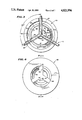
- FIG. 6 is a top plan view of a rotary selection member removably mountable on the base member of the valve system and illustrated with a closing cap;
- FIG. 7 is a bottom plan view of the rotary selection member of FIG. 6;
- FIG. 8 is a view in section of the rotary selection member taken along plane 8-8 of FIG. 6;
- FIGS. 9A through 9D are enlarged fragmentary views illustrating the cooperation between the base member and the selection member as the selection member is rotated to unclamp and then clamp a tubing member;
- FIG. 9E is an enlarged fragmentary view of an alternate valve opening
- FIG. 10A is a front plan view of a spring biasing indexing member affixable to the base member of the valve system
- FIG. 10B is a view in section taken along plane 10B--10B of FIG. 10A;
- FIGS. 11A through 11F illustrate schematically a method of practicing peritoneal dialysis in accordance with the present invention
- FIG. 12 is an enlarged perspective view, partly broken away, of an alternate embodiment of the present valve system.
- FIG. 13 is a perspective view of the selecting member illustrating a fluid flow indicator thereon.
- FIG. 1A illustrates a system 10 in accordance with the present invention.
- the system 10 is in fluid flow communication with a peritoneal catheter C of a patient P.
- the system 10 facilitates and assists the patient P in carrying out the drain and fill cycles required several times a day in connection with continuous ambulatory peritoneal dialysis (CAPD).
- CAPD continuous ambulatory peritoneal dialysis
- the system 10 provides a way to proceed very systematically through the necessary steps of each drain and fill cycle to minimize the possibility of the omission of steps and to minimize the possibility of the interchange of steps.
- the system 10 includes two major components.
- the first component is a fluid transfer set 12.
- the second component is a reusable rotary valve system 14 which receives a section of the transfer set 12 for the purpose of regulating fluid flow to and from the patient P by means of selected flexible conduit members of the set 12.
- the set 12 may be variously constructed.
- the set 12 includes first and second flexible, preferably elastic or plastic, fluid flow conduits 20 and 22.
- Each of the conduits 20 and 22 is in fluid flow communication at a proximal end with a fluid flow Y junction 24.
- the junction 24 is also in fluid flow communication with a central tubing member 26.
- the tubing member 26 is couplable via a standard tubing connector member 28 to a relatively short exchange set 30.
- the exchange set 30 can be removably coupled to an external end of the catheter C by a standard titanium catheter connector 32 of a commercially available type. Alternately, the connector 28 on the tubing member 26 could be directly connected to the catheter connector 32.
- Distal ends 38 and 40 of tubing members 20 and 22 can be coupled to first and second dialysis solution containers 42 and 44.
- the containers 42 and 44 can be removably coupled to the distal ends 38 and 40 by means of standard spike connectors, such as the spike connector 46 illustrated in FIG. 1.
- the set 12 can be fabricated as a single use set with an empty dialysis solution container, such as the container 44, fixedly attached to the distal end 40.
- the valve system 14 has a circular base assembly 50 and a flow controlling rotary, removably engageable, selection ring 52.
- the selection ring 52 is slidably received on the base member 50 at only one rotational insertion-removal position, with respect to the base 50.
- Arrow 14a indicates linear movement of the ring 52 onto and away from the base 50 at the insertion-removal position.
- the selection ring 52 is rotatable in only one direction 54 through a sequence of predetermined positions for the purpose of closing and opening the fluid flow conduits 20, 22 and 26 of the set 12 in a predetermined sequence to carry out a drain and fill cycle as required by the patient P.
- a circular cap 56 can be used to close the top of the selection ring 52.
- valve system 14 is particularly advantageous in that a substantial mechanical advantage is provided by the selection ring 52 such that even a person of limited, physical strength can readily open and close the required conduits. Further, use of the valve system 14 insures that the conduits 20, 22 and 26 will be opened and closed only in a predetermined sequence of the type necessary to carry out the desired drain and fill portion of the dialysis procedure.
- the valve system 14 is also advantageous in that it is reusable by the patient P. Further, since the valve system 14 exerts pressure external to the conduits 20, 22 and 26 of the set 12, there is no possibility that it will impair the sterility or the aseptic condition of the set 12 during the drain and fill cycle.
- the base member 50 includes an upper, generally cylindrical portion 60 with a discontinuous, radially directed flange 62 formed on an upper surface 64.
- the flange 62 provides a locking member, fixed with respect to the base 50, which slidably engages a mating member formed within the selection ring 52 for the purpose of rotatably locking the selection ring 52 to the base 50 except at the single insertion-removal location.
- the system 10 When being used to conduct a drain and fill procedure, the system 10 can be positioned on a flat surface, such as a table.
- the base member 50 which preferably light weight, can include a nonskid bottom, such as by using friction pads or suction cups, so that the selection ring 52 may be rotated by the patient P without the necessity of holding or restraining the base portion 50.
- the upper cylindrical section 60 also includes a plurality of spaced, axially directed slots 66.
- Each of the slots 66 is formed with first and second spaced apart, axially directed surfaces 66a and 66b. In the illustrated embodiment, the slots 66 are spaced at 120 degree intervals around the cylindrical section 60. However, the degree of arcuate spacing can vary and is not a limitation on the present invention.
- the tubing members 20, 22 and 26 are intended to extend through the slots 66 as illustrated in FIG. 1A.
- Each of the slots 66 includes a radially extending lower portion 68 on which the respective tubing members 20, 22 and 26 are positioned. The radially extending portions 68 provide means which cooperate with the rotatable selection ring 52 to clamp or close off the respective tubing members.
- the patient P places the valve system 14 on a flat surface, and installs the set 12 therein.
- the junction member 24 carries a selectively shaped region or key 24a, so that the set 12 can be properly inserted into the valve system 14 with only one orientation. This assists the patient in properly aligning the set 12 relative to the valve system 14.
- the key 24a can be variously configured, according to the configuration and manipulation required of the set 12. Alternately, the set 12 could be without a key 24a, placing the orientation of the set 12 within the valve system 14 entirely in the patient's discretion.
- the patient then couples the set 12 to the exchange set 30, and couples a fresh bag 42 of dialysis solution to the set 12.
- the patient P can proceed through the necessary drain and fill cycle.
- the selection ring can be rotated into a shut-off position, the set 12 is uncoupled from the exchange set 30.
- the selection ring 52 is then rotated into its insertion-removal position and removed from the base 50.
- the set 12 can then be removed from the base 50 and stored for use in a subsequent exchange session. It could, for example, be stored in the closed O-shaped configuration disclosed in co-pending U.S. patent application Ser. No. 552,936 entitled "Detachable Peritoneal Dialysis Set.” Alternately, the set 12 can be disposed of, and a new set 12 used in the next subsequent exchange session.
- FIG. 2 illustrates an alternate valve system 15.
- the valve system 15 includes a base 51 and a linearly displaceable selection member 53.
- a fluid flow transfer set 13 can be positioned on the base 51.
- the selection member 53 can be moved linearly so as to open and close the fluid flow members of the set in a predetermined sequence.
- FIG. 3 is a top view of the base 50 with the set 12 positioned therein.
- the axially oriented slots 66 are spaced at 120 degree intervals around the base 50.
- the discontinuous, radially extending flanges 62 are shown formed adjacent the upper surface 64 of the cylindrical housing member 60.
- the slots 70 through 74 define the insertion-release position of the selection ring 52 with respect to the base 50.
- the slots 70 and 72 are offset with respect to the slot 74 such that the rotary selection member 52 can only be rotatably engaged with the flanges 62 when correctly aligned with respect to the orientation slots 70, 72 and 74.
- a two-part key 78 and 80 Centrally located on the base 50 is a two-part key 78 and 80.
- the key formed of the parts 78 and 80 cooperates with the correspondingly-shaped key 24a of the Y junction member 24 to insure that the set 12 can only be inserted into the base 50 with a single orientation.
- the key member 24a has a web or key section with a 120° arc and a first radius and a web or key section with a 120° arc and a second, smaller radius.
- the asymmetrical structure of the sections 78, 80 of the base member 50 cooperates with the asymmetrical structure of key member 24a such that the set 12 can be properly inserted into the base 50 with only one orientation.
- the key 24a can be formed with various other configurations using, for example, differing arcs with each arc having the same or different radius.
- annular slot 82 is provided in the base section 50.
- the annular slot 82 intersects the radially-directed lower portions 68 of the tubing receiving slots 66.
- a flexible member is positioned in the annular slot 82 against which the corresponding tubing member can be clamped closed.
- FIG. 4 is a bottom view of the base 50.
- the overall relationship between the spaced apart key members 78 and 80 and the axially extending tubing receiving slots 66 can be seen in FIG. 3.
- FIG. 5 a view in section of the base 50 taken along plane 5--5 of FIG. 4, further illustrates the structure of the base member 50.
- the discontinuous radially extending flange 62 can be seen in FIG. 5.
- a lower bearing surface 62a of the flange 62 provides a surface against which the selection ring 52 can slidably rotate.
- FIG. 5 also illustrates the annular slot 82 utilized in connection with clamping shut the various tubing members, such as the fragmentary portion of the tubing member 26.
- Positioned in the annular slot 82 is either an O-ring 84 or a flat, circular gasket 86.
- the O-ring 84 or the gasket 86 could be formed of a variety of resilient materials.
- the members 84 and 86 provide a deformable surface against which portions of the respective tubing members 20, 22 and 26 can be forced and clamped for the purpose of closing off fluid flow therethrough.
- the annular slot 82 and the resilient member 84 or 86 cooperate with an axially extending force applying member in the selection ring 52 for the purpose of clamping a part of respective tubing member therebetween.
- FIG. 6 illustrates in a top planar view, the rotatable selection ring 52.
- the ring 52 has a generally circular exterior peripheral surface 90.
- the peripheral surface 90 is interrupted by a plurality of spaced-apart, finger grippable depressions 92.
- the depressions 92 provide additional gripping surface so that the patient P can readily rotate the selection ring 52.
- the ring 52 defines an internal cylindrical surface 94.
- Formed on the interior cylindrical surface 94 are three inwardly extending flange members 96a, 96b and 96c (illustrated in phantom).
- the members 96a through 96c are spaced apart on 120 degree intervals so as to slidably engage the axially-oriented slots 66 in the upper cylindrical portion 60 of the base 50 at the insertion-removal location.
- the inwardly extending flanges 96a through 96c Interspaced between the inwardly extending flanges 96a through 96c are three spaced apart, orientation identifying flanges 100, 102 and 104 (illustrated in phantom).
- the flanges 100 and 102 correspond to the slots 70 and 72 of the base member 50.
- the inwardly extending offset flange 104 matches the offset slot 74 in the base 50 when the cylindrical selection ring 52 is oriented at its insertion-removal position.
- the selection ring 52 can only be engaged with the base 50 at this single, predetermined, insertion-removal position. Subsequent to positioning the selection ring 52 on the base member 50 and rotating the selection ring in the direction 54, each of the inwardly extending flanges 96a through 96c and 100 through 104 slidably engages the lower surface 62a of the discontinuous annular flange 62. Hence, the selection ring 52 cannot be removed from the base 50 until it is returned to its initial insertion-removal position.
- FIG. 7 a bottom plan view of the selection ring member 52 further illustrates the relative relationships of the flanges 96a through 96c and 100 through 104.
- a discontinuous annular surface 110 is formed along a lower edge 112 of the rotatable selection member 52. The discontinuous annular surface 110 is positioned between first and second biased surfaces 114 and 116.
- the discontinuous annular surface 110 cooperates with the deformable member, either 84 or 86 as illustrated in FIG. 5, to externally apply clamping forces to sections of one or more of the tubing members 20, 24 and 26 extending through the slots 68 for the purpose of blocking fluid flow there-through.
- Two valve openings, or discontinuities, 120 and 122 are spaced 120 degrees apart from one another in the surface 110.
- the discontinuities 120, 122 provide openings for the purpose of relieving the clamping force applied to the respective tubing member and permitting the flow of fluid therethrough.
- the tubing members 120, 122 and 126 extend through respective slots 66 at spaced apart 120 degree angles. Hence, a maximum of two tubing members can be unclamped for fluid flow communication using the exemplary valve system 14. It will be understood that the precise number of discontinuities in the annular surface 110 is not a limitation of the present invention.
- FIG. 8 illustrates a sectional view of the rotary selection ring 52 taken along plane 8--8 of FIG. 6.
- the clamping annular surface 110 is positioned between the two biased surfaces 114 and 116.
- a lip 56a is provided upon which the cap 56 rests.
- the cap 56 can be fixedly attached to the ring 52 in any one of a variety of ways including screws, pins or adhesive.
- FIGS. 9A-9D fragmentary, enlarged views illustrate the shape of the valve openings 120, 122.
- FIGS. 9A-9D illustrate the process of unclamping and reclamping a tubular member such as the member 22.
- Valve opening 120 is illustrated and it is identical to valve opening 122.
- the rotating interrelationship between selection ring 52 and base member 50 is illustrated.
- An exemplary section of the hollow tubing member 22 is illustrated with respect to the valve opening 120. Adjacent the tubing member 22 is a deflected section 84a of the deformable O-ring 84 which is in turn positioned adjacent the lower surface 82a of the annular slot 82.
- the illustrated valve opening 120 is formed with a first convex circular surface 126 of a radius on the order of 0.120 inches.
- the surface 126 smoothly engages a concave surface 128 with radius on the order of 0.135 inches.
- the surface 128 terminates in a surface region 130 oriented at a 45° angle with respect to the annular ring 110.
- the surface 130 rejoins the annular ring 110 via a gently curved region 132 of radius on the order of 0.135 inches.
- FIG. 9A the tubing member 22 is shown clamped against the region 84a of the deformable member 84.
- the member 84 is slightly deformed in the region 84a.
- the valve opening 120 unclamps the tubing member 22 as illustrated in FIG. 9B permitting a flow of fluid therethrough.
- the relative position of the base 50 and selection ring 52, as in FIG. 9B, corresponds to one of a plurality of predetermined flow defining index positions.
- FIG. 9E illustrates an alternate valve opening 120a.
- the valve opening 120a is formed with a planar surface 128a as opposed to the circular surface 128.
- the planar terminating surface 130a intersects the annular clamping surface 110 without an intervening convex surface such as the surface 132.
- an opening can be formed with a biased surface 128b, illustrated in phantom in FIG. 9E.
- a biased surface 128b illustrated in phantom in FIG. 9E.
- Such a surface provides for a gradual release of the closure forces as the member 52 is rotated.
- the stepped surface 128c shown in solid lines in Figure. 9E catches against the tubing 22 during movement of the selection member 52 in a direction opposite to the intended direction 54.
- the lodgment of the stepped surface 128c against the tubing 22 serves as a rachet, preventing movement of the selection member 52 in this unintended opposite direction.
- FIG. 9A through 9D illustrate the cooperative interaction between the base member 50 and the rotary selection ring 52 as the ring 52 is rotated.
- a closed or clamped tubing member 22 is unclamped so that fluid can flow therethrough.
- the tubing member 22 is again clamped shut, blocking the flow of fluid therethrough.
- FIGS. 10A and 10B illustrate a nonreversing indexing member 140 which provides for locking the rotary selection member 52 into one of a plurality of predetermined index locations, with respect to the base 50, as the member 52 is rotated.
- the indexing member may be variously constructed. For example, it can take the form of a rachet.
- the indexing member 140 is spring biased.
- the spring member 140 has an end 142 which can be affixed to the base member 50 adjacent locating notch 144.
- a free end 146 of the spring member 140 can slidably engage a plurality of slots, such as the slots 148a through d formed on the interior surface 94 of the selection member 52 (best seen in FIG. 8).
- the slots 148a through 148d are shaped such that a curved end region 150 of the end 146 can slide into and out of a respective slot as the selection member 52 is rotated in the direction 54.
- FIGS. 11A through 11F illustrate schematically a method of carrying out a peritoneal dialysis drain and fill cycle in accordance with the present invention.
- the set 12 and the valve system 14 are illustrated schematically in FIGS. 11A through 11F.
- FIG. 11A the set 12 is mounted on the base 50 with the keyed Y junction 24 engaging the mating portion of the base 50.
- An empty dialysis solution container 44 is shown affixed to the conduit 22 which will be used as the drain line.
- a full dialysis solution container 42, containing fresh solution, is shown adjacent the distal end 40 of the line 20 which will be used as the fill line.
- the distal end of the line 26 with connector 28 is shown adjacent the end of the connection set 30 which is coupled to the catheter C of the patient P.
- FIG. 11B illustrates the valve system 14 with the rotary selection member 52 mounted thereon and positioned in a first index position.
- tubing members 20, 22 and 26 are all clamped shut.
- the fresh bag of dialysis solution 42 has been coupled to the distal end 40 of the tubing member 20.
- the tubing member 26, via the connection set 30 has been coupled to the external end of the catheter C.
- FIG. 11C illustrates schematically a flush sequence with selection member 52 having been rotated to a second index position.
- Tubing member 20 has been placed in fluid flow communication with line 22 permitting a flushing flow of fresh fluid from the container 42 of dialysis fluid to the empty container 44.
- Arrows along the tubing members 20 and 22 indicate a direction of fluid flow.
- the flush operation can continue on the order for 5 to 10 seconds or so.
- FIG. 11D illustrates selection member 52 having been rotated to a third index position wherein tubing members 26 and 22 are placed in fluid flow communication. Fluid in the peritoneal cavity of the patient P can then flow through the catheter C and, via the lines 26 and 22, drain into the essentially empty dialysis solution container 44. The container 44 then becomes filled with drained or spent dialysis solution. The drain portion of the cycle takes place under the flow of gravity and continues for about 15-20 minutes.
- FIG. 11E illustrates the selection member 52 having been rotated to a fourth index position wherein the tubing member 20 is placed in fluid flow communication with the tubing member 26 in order that fresh dialysis solution can flow from the container 42, through patient's catheter into the patient's peritoneal cavity.
- the fill portion of the cycle takes place under the influence of the force of gravity and takes on the order of 10-15 minutes.
- FIG. 11F illustrates the selection member 52 having been rotated to a fifth index position wherein the fluid flow lines 20, 22 and 26 are all clamped shut.
- the container 42 which originally contained fresh dialysis solution, is essentially empty.
- the container 44 which started as an empty container is essentially filled with spent dialysis solution.
- the tubing member 25 is now disconnected from the connection set 30 and the patient's catheter C. The drain and fill cycle has beem completed.
- the valve system 14 can then be returned to storage until the end of the dwell period when it is time to carry out the next drain and fill cycle. If a reusable set is being used, it is placed in storage until the end of the dwell period.
- FIG. 12 illustrates an alternate embodiment 160 of the present fluid flow control valve.
- the valve 160 includes a base member 162 and a rotary selection member 164.
- the base member 162 is similar to the base member 50. However, the base member 162 is somewhat modified.
- the base member 162 includes a plurality of gripable surfaces 166 positioned about an exterior peripheral surface thereof.
- a gripable projection or lobe 168 has been affixed to one side of the base member 162.
- a set of discontinuous threads 170 is provided spaced about a cylindrical body portion 172 of the base member 162.
- the threads 170 are angled such that the selecting member 164 can be threaded onto and screwed down onto the base member 162.
- the selecting member 164 carries a set of matching threads 170a.
- Each of the discontinuous threads 170 has a biased surface 174a which slideably engages a corresponding surface positioned on the threads 170a in the selecting member 164 as the selecting member is being rotated onto the base member 162. This cooperative interaction draws the selecting member 164 down onto the base 162 and simultaneously crimps the tubing members 26 closed as the member 164 is rotated.
- Each of the discontinuous threads 170 terminates in a biased surface 174b.
- the surface 174b provides clearance for the threads 170a carried on the selecting member 164.
- Some threads 170 terminate adjacent the slots 66 at axially oriented surfaces 174c.
- the axially oriented surfaces 174c are essentially perpendicular to the plane of rotation of the member 164.
- the selecting member 164 includes a manually gripable projection or lobe 178 corresponding to the projection 168 affixed to the base member 162.
- a cylindrically shaped alignment member 180 has been provided within the selecting member 164.
- the cylindrical alignment member 180 slideably engages an interior peripheral surface 182 of the cylindrical member 172. This engagement occurs prior to the engagement of the threaded members 170 with the corresponding threaded members 170a in the selecting member 164.
- the selecting member 164 also includes on a top surface 182 a flow diagram 184 useable to indicate which tubing members are open and which tubing member is clamped shut. This provides a visual indicia of the expected direction of fluid flow to assist the user.
Abstract
Description
Claims (47)
Priority Applications (1)
| Application Number | Priority Date | Filing Date | Title |
|---|---|---|---|
| US07/008,012 US4821996A (en) | 1987-01-28 | 1987-01-28 | Fluid flow control valve and transfer set |
Applications Claiming Priority (1)
| Application Number | Priority Date | Filing Date | Title |
|---|---|---|---|
| US07/008,012 US4821996A (en) | 1987-01-28 | 1987-01-28 | Fluid flow control valve and transfer set |
Publications (1)
| Publication Number | Publication Date |
|---|---|
| US4821996A true US4821996A (en) | 1989-04-18 |
Family
ID=21729336
Family Applications (1)
| Application Number | Title | Priority Date | Filing Date |
|---|---|---|---|
| US07/008,012 Expired - Lifetime US4821996A (en) | 1987-01-28 | 1987-01-28 | Fluid flow control valve and transfer set |
Country Status (1)
| Country | Link |
|---|---|
| US (1) | US4821996A (en) |
Cited By (54)
| Publication number | Priority date | Publication date | Assignee | Title |
|---|---|---|---|---|
| US4946434A (en) * | 1986-07-22 | 1990-08-07 | Haemonetics Corporation | Disposable manifold and valve |
| WO1993019808A1 (en) * | 1992-04-07 | 1993-10-14 | Innovata Biomed Limited | Connecting device |
| US5496270A (en) * | 1994-09-26 | 1996-03-05 | Megadyne Medical Products, Inc. | Tri-tubular suction irrigation device |
| DE4443714A1 (en) * | 1994-12-09 | 1996-06-20 | Fresenius Ag | Device for connecting several hose sections |
| DE19726550A1 (en) * | 1997-06-23 | 1999-02-04 | Walz Karl Heinz | Automatic reversing valve for alternate opening and closing soft tubes |
| DE19726549A1 (en) * | 1997-06-23 | 1999-02-18 | Walz Karl Heinz | Hose for waste water sample abstraction closed by rotor squeezing hose |
| WO2000045876A1 (en) * | 1999-02-05 | 2000-08-10 | Gambro Ab | Fluid routing device |
| USRE37074E1 (en) | 1988-11-04 | 2001-02-27 | Baxter Intl. Inc. | Pumping device having inlet and outlet valves adjacent opposed sides of a tube deforming device |
| EP1106191A1 (en) * | 1998-08-19 | 2001-06-13 | JMS Co., Ltd. | Fluid passage change-over apparatus for medical treatment |
| US6308737B1 (en) | 2000-03-10 | 2001-10-30 | Transonic Systems, Inc. | Method and apparatus for selectively reversing flow between a dialyzer and a patient access |
| US20030116731A1 (en) * | 2001-12-04 | 2003-06-26 | William A. Cook Australia Pty Ltd. | Access valve |
| WO2004022151A1 (en) * | 2002-09-06 | 2004-03-18 | Gambro Lundia Ab | Multiway wave |
| US20040199190A1 (en) * | 2001-10-05 | 2004-10-07 | Viola Frank J. | Barrel pinch fastener and applier |
| WO2005046786A1 (en) * | 2003-11-12 | 2005-05-26 | Gobat, Suministros Medicos, S.L. | Improved three-way valve |
| US20050131335A1 (en) * | 2003-12-11 | 2005-06-16 | Gambro Lundia Ab. | Switching device and apparatus for controlling flow of a fluid |
| US20060079827A1 (en) * | 2004-10-07 | 2006-04-13 | Mel Jensen | Blood flow reversal valves and related systems and methods |
| US20060178632A1 (en) * | 2000-10-18 | 2006-08-10 | Trombley Frederick W Iii | Injector system with a manual control device |
| US20060259013A1 (en) * | 2005-05-10 | 2006-11-16 | Ranalletta Joseph V | Sterile docking apparatus and method |
| EP1741823A1 (en) * | 2005-07-05 | 2007-01-10 | De'Longhi SpA | Device to regulate the flow of steam in a domestic electrical appliance |
| US20070161946A1 (en) * | 2004-02-27 | 2007-07-12 | Iperboreal Pharma S.R.L. | Apparatus for applying and removing closing means from an end portion of a tubular element and the use thereof in peritoneal dialysis |
| WO2008110629A3 (en) * | 2007-03-14 | 2008-12-24 | Coloplast As | A switching device and an irrigation system comprising the device |
| US20090112164A1 (en) * | 2007-10-30 | 2009-04-30 | Medrad, Inc. | System and method for proportional mixing and continuous delivery of fluids |
| US20090143723A1 (en) * | 2007-11-29 | 2009-06-04 | Baxter International Inc. | Flow control device for peritoneal dialysis |
| US20090221933A1 (en) * | 2005-07-14 | 2009-09-03 | C.R. Bard, Inc. | Intra-abdominal pressure monitoring system |
| US20100114040A1 (en) * | 2008-11-05 | 2010-05-06 | Medrad, Inc. | Fluid mixing control device for a multi-fluid delivery system |
| US20100186838A1 (en) * | 2009-01-28 | 2010-07-29 | Aeromaster Innovations Inc. | Alternating State Flow Valve |
| US20100217179A1 (en) * | 2009-02-20 | 2010-08-26 | Baxter International Inc. | Bulk delivery peritoneal dialysis system and method |
| US20100249663A1 (en) * | 2007-10-23 | 2010-09-30 | C.R. Bard, Inc. | Continuous intra-abdominal pressure monitoring system |
| US20100276011A1 (en) * | 2009-01-28 | 2010-11-04 | Spitzer Jeffrey J | Alternating state flow valve |
| US20100292633A1 (en) * | 2006-08-11 | 2010-11-18 | Iperboreal Pharma S.R.L. | Coupling device and use thereof |
| CN102481402A (en) * | 2009-08-26 | 2012-05-30 | 医研比赫国际股份公司 | An irrigation device and method of using the device |
| CN103751871A (en) * | 2013-05-06 | 2014-04-30 | 北京智立医学技术股份有限公司 | Peritoneal dialysis treatment device and operation method thereof |
| KR101483619B1 (en) * | 2014-09-16 | 2015-01-19 | 배동수 | Multifunction drink selector and straw for drink using the same |
| US20150088055A1 (en) * | 2013-09-24 | 2015-03-26 | Ta-Lun Tan | Multi-path control valve |
| CN105263543A (en) * | 2013-03-04 | 2016-01-20 | 安多美达医疗系统有限公司 | Device for regulating a volumetric flow rate |
| US9415151B2 (en) | 2012-09-25 | 2016-08-16 | Fresenius Medical Care Holdings, Inc. | Blood flow reversal valves and related systems and methods |
| US9433730B2 (en) | 2013-03-14 | 2016-09-06 | Bayer Healthcare Llc | Fluid mixing control device for a multi-fluid delivery system |
| RU169267U1 (en) * | 2016-03-09 | 2017-03-13 | Адиль Алимович Омеров | Peritoneal dialysis faucet |
| US9700672B2 (en) | 2011-09-21 | 2017-07-11 | Bayer Healthcare Llc | Continuous multi-fluid pump device, drive and actuating system and method |
| EP3151907A4 (en) * | 2014-06-09 | 2018-01-10 | Bayer Healthcare LLC | Tubing assembly |
| CN108506519A (en) * | 2018-03-30 | 2018-09-07 | 中国科学院力学研究所 | A kind of miniature program-controlled rotary extrusion type spinning pinch valve |
| CN109200369A (en) * | 2018-11-07 | 2019-01-15 | 郑州大学第附属医院 | A kind of peritoneal dialysis unit |
| US10195112B2 (en) | 2012-11-26 | 2019-02-05 | Becton Dickinson France | Adaptor for multidose medical container |
| DE102018204554B3 (en) | 2018-03-26 | 2019-04-18 | Festo Ag & Co. Kg | pinch |
| US10286122B2 (en) * | 2015-10-21 | 2019-05-14 | Lifecell Corporation | Systems and methods for tube management |
| US10314955B2 (en) | 2015-10-21 | 2019-06-11 | Lifecell Corporation | Systems and methods for medical device control |
| US10507319B2 (en) | 2015-01-09 | 2019-12-17 | Bayer Healthcare Llc | Multiple fluid delivery system with multi-use disposable set and features thereof |
| WO2020065348A1 (en) * | 2018-09-28 | 2020-04-02 | University Of Leeds | Valve |
| US10744254B1 (en) * | 2019-02-18 | 2020-08-18 | Simergent, LLC | Automated peritoneal dialysis device |
| US11091733B2 (en) | 2016-08-30 | 2021-08-17 | Lifecell Corporation | Systems and methods for medical device control |
| US11213669B2 (en) * | 2014-10-10 | 2022-01-04 | Nxstage Medical, Inc. | Pinch clamp devices, methods, and systems |
| US11261418B2 (en) | 2012-09-06 | 2022-03-01 | The Gid Group, Inc. | Tissue processing apparatus and method for processing adipose tissue |
| US11376360B2 (en) | 2016-07-18 | 2022-07-05 | Bayer Healthcare Llc | Fluid injector and patient set therefor |
| EP3958950A4 (en) * | 2019-04-25 | 2022-11-16 | Fresenius Medical Care Deutschland GmbH | Device for controlling fluid flow and set for peritoneal dialysis comprising said device |
Citations (18)
| Publication number | Priority date | Publication date | Assignee | Title |
|---|---|---|---|---|
| US2838270A (en) * | 1952-09-08 | 1958-06-10 | All Power Mfg Co | Handle structures for valves and the like |
| US3016915A (en) * | 1959-09-24 | 1962-01-16 | Image Transfer Inc | Valve |
| US3411534A (en) * | 1966-12-28 | 1968-11-19 | Tracor | Four-way valve |
| US3444896A (en) * | 1967-01-18 | 1969-05-20 | William B Wilson | Hydraulic interval timer |
| US3459182A (en) * | 1966-08-08 | 1969-08-05 | Reese Res Found | Blood administration method |
| US3515170A (en) * | 1967-12-04 | 1970-06-02 | Corning Glass Works | Constriction valve for flexible tubes |
| US3575161A (en) * | 1968-03-07 | 1971-04-20 | Seymour B London | Valve for biological systems |
| US3805842A (en) * | 1973-01-15 | 1974-04-23 | Emco Ltd | Pinch tube faucet |
| US3918490A (en) * | 1973-12-20 | 1975-11-11 | George Goda | Fluid switching apparatus |
| US3920215A (en) * | 1973-02-09 | 1975-11-18 | Dieter W Knauf | Valve |
| US3960224A (en) * | 1975-06-06 | 1976-06-01 | Charles Silvers | Precision cut-off weighing apparatus |
| US3985134A (en) * | 1973-11-26 | 1976-10-12 | Rhone-Poulenc S.A. | Extracorporeal blood circuit |
| US4061142A (en) * | 1976-06-16 | 1977-12-06 | Sandoz, Inc. | Apparatus for controlling blood flow |
| US4360007A (en) * | 1980-08-05 | 1982-11-23 | Yeda Research And Development Co., Ltd. | Remote controlled magnetic actuator particularly for an implantable device like a valve |
| US4425116A (en) * | 1980-04-14 | 1984-01-10 | Baxter Travenol Laboratories, Inc. | Control system for fluid flow apparatus |
| US4425113A (en) * | 1982-06-21 | 1984-01-10 | Baxter Travenol Laboratories, Inc. | Flow control mechanism for a plasmaspheresis assembly or the like |
| US4428745A (en) * | 1982-06-21 | 1984-01-31 | Baxter Travenol Laboratories, Inc. | Flow control mechanism for a plasmapheresis assembly or the like |
| US4457339A (en) * | 1982-03-03 | 1984-07-03 | Coulter Electronics, Inc. | Multiprogrammable pinch valve module |
-
1987
- 1987-01-28 US US07/008,012 patent/US4821996A/en not_active Expired - Lifetime
Patent Citations (18)
| Publication number | Priority date | Publication date | Assignee | Title |
|---|---|---|---|---|
| US2838270A (en) * | 1952-09-08 | 1958-06-10 | All Power Mfg Co | Handle structures for valves and the like |
| US3016915A (en) * | 1959-09-24 | 1962-01-16 | Image Transfer Inc | Valve |
| US3459182A (en) * | 1966-08-08 | 1969-08-05 | Reese Res Found | Blood administration method |
| US3411534A (en) * | 1966-12-28 | 1968-11-19 | Tracor | Four-way valve |
| US3444896A (en) * | 1967-01-18 | 1969-05-20 | William B Wilson | Hydraulic interval timer |
| US3515170A (en) * | 1967-12-04 | 1970-06-02 | Corning Glass Works | Constriction valve for flexible tubes |
| US3575161A (en) * | 1968-03-07 | 1971-04-20 | Seymour B London | Valve for biological systems |
| US3805842A (en) * | 1973-01-15 | 1974-04-23 | Emco Ltd | Pinch tube faucet |
| US3920215A (en) * | 1973-02-09 | 1975-11-18 | Dieter W Knauf | Valve |
| US3985134A (en) * | 1973-11-26 | 1976-10-12 | Rhone-Poulenc S.A. | Extracorporeal blood circuit |
| US3918490A (en) * | 1973-12-20 | 1975-11-11 | George Goda | Fluid switching apparatus |
| US3960224A (en) * | 1975-06-06 | 1976-06-01 | Charles Silvers | Precision cut-off weighing apparatus |
| US4061142A (en) * | 1976-06-16 | 1977-12-06 | Sandoz, Inc. | Apparatus for controlling blood flow |
| US4425116A (en) * | 1980-04-14 | 1984-01-10 | Baxter Travenol Laboratories, Inc. | Control system for fluid flow apparatus |
| US4360007A (en) * | 1980-08-05 | 1982-11-23 | Yeda Research And Development Co., Ltd. | Remote controlled magnetic actuator particularly for an implantable device like a valve |
| US4457339A (en) * | 1982-03-03 | 1984-07-03 | Coulter Electronics, Inc. | Multiprogrammable pinch valve module |
| US4425113A (en) * | 1982-06-21 | 1984-01-10 | Baxter Travenol Laboratories, Inc. | Flow control mechanism for a plasmaspheresis assembly or the like |
| US4428745A (en) * | 1982-06-21 | 1984-01-31 | Baxter Travenol Laboratories, Inc. | Flow control mechanism for a plasmapheresis assembly or the like |
Cited By (106)
| Publication number | Priority date | Publication date | Assignee | Title |
|---|---|---|---|---|
| US4946434A (en) * | 1986-07-22 | 1990-08-07 | Haemonetics Corporation | Disposable manifold and valve |
| USRE37074E1 (en) | 1988-11-04 | 2001-02-27 | Baxter Intl. Inc. | Pumping device having inlet and outlet valves adjacent opposed sides of a tube deforming device |
| WO1993019808A1 (en) * | 1992-04-07 | 1993-10-14 | Innovata Biomed Limited | Connecting device |
| GB2280247A (en) * | 1992-04-07 | 1995-01-25 | Innovata Biomed Ltd | Connecting device |
| GB2280247B (en) * | 1992-04-07 | 1995-08-30 | Innovata Biomed Ltd | Fluid-directing connecting devices for medical appliances |
| US5496270A (en) * | 1994-09-26 | 1996-03-05 | Megadyne Medical Products, Inc. | Tri-tubular suction irrigation device |
| DE4443714A1 (en) * | 1994-12-09 | 1996-06-20 | Fresenius Ag | Device for connecting several hose sections |
| DE19726550A1 (en) * | 1997-06-23 | 1999-02-04 | Walz Karl Heinz | Automatic reversing valve for alternate opening and closing soft tubes |
| DE19726550C2 (en) * | 1997-06-23 | 1999-05-27 | Walz Karl Heinz | Switch valve |
| DE19726549C2 (en) * | 1997-06-23 | 1999-08-26 | Walz | Hose valve |
| DE19726549A1 (en) * | 1997-06-23 | 1999-02-18 | Walz Karl Heinz | Hose for waste water sample abstraction closed by rotor squeezing hose |
| US6589197B1 (en) * | 1998-08-19 | 2003-07-08 | Jms Co., Ltd. | Fluid passage change-over apparatus for medical treatment |
| EP1106191A1 (en) * | 1998-08-19 | 2001-06-13 | JMS Co., Ltd. | Fluid passage change-over apparatus for medical treatment |
| EP1106191A4 (en) * | 1998-08-19 | 2007-11-07 | Jms Co Ltd | Fluid passage change-over apparatus for medical treatment |
| WO2000045876A1 (en) * | 1999-02-05 | 2000-08-10 | Gambro Ab | Fluid routing device |
| US6308737B1 (en) | 2000-03-10 | 2001-10-30 | Transonic Systems, Inc. | Method and apparatus for selectively reversing flow between a dialyzer and a patient access |
| US9764081B2 (en) | 2000-10-18 | 2017-09-19 | Bayer Healthcare Llc | Fluid path containing a pressure isolation valve |
| US8747358B2 (en) | 2000-10-18 | 2014-06-10 | Bayer Medical Care Inc. | Injector system with a manual control device |
| US20060178632A1 (en) * | 2000-10-18 | 2006-08-10 | Trombley Frederick W Iii | Injector system with a manual control device |
| US9833559B2 (en) | 2000-10-18 | 2017-12-05 | Bayer Healthcare Llc | Pressure isolation mechanisms, method of use thereof and fluid delivery systems including pressure isolation mechanisms |
| US7951160B2 (en) | 2001-10-05 | 2011-05-31 | Tyco Healthcare Group Lp | Barrel pinch fastener and applier |
| US20040199190A1 (en) * | 2001-10-05 | 2004-10-07 | Viola Frank J. | Barrel pinch fastener and applier |
| AU2002362737B2 (en) * | 2001-10-05 | 2008-05-29 | Covidien Lp | Barrell pinch fastener and applier |
| US7371246B2 (en) * | 2001-10-05 | 2008-05-13 | Tyco Healthcare Group Lp | Barrel pinch fastener and applier |
| US6860463B2 (en) * | 2001-12-04 | 2005-03-01 | William A. Cook Australia Pty. Ltd. | Access valve |
| US20030116731A1 (en) * | 2001-12-04 | 2003-06-26 | William A. Cook Australia Pty Ltd. | Access valve |
| AU2003255868B2 (en) * | 2002-09-06 | 2008-07-03 | Fresenius Medical Care Deutschland Gmbh | Multiway Valve |
| US7469716B2 (en) | 2002-09-06 | 2008-12-30 | Gambro Lundia Ab | Multiway valve |
| KR101148085B1 (en) * | 2002-09-06 | 2012-05-22 | 프레제니우스 메디칼 케어 도이칠란드 게엠베하 | Multiway valve |
| WO2004022151A1 (en) * | 2002-09-06 | 2004-03-18 | Gambro Lundia Ab | Multiway wave |
| US20060005886A1 (en) * | 2002-09-06 | 2006-01-12 | Andrea Parrino | Multiway wave |
| WO2005046786A1 (en) * | 2003-11-12 | 2005-05-26 | Gobat, Suministros Medicos, S.L. | Improved three-way valve |
| US20080275399A1 (en) * | 2003-11-12 | 2008-11-06 | Vicente Gomez Amor | Perfected 3 Way Stopcock |
| US7914495B2 (en) | 2003-11-12 | 2011-03-29 | Gobat Suministros Medicos, S.L. | Three-way stopcock |
| WO2005061043A1 (en) * | 2003-12-11 | 2005-07-07 | Gambro Lundia Ab | Switching device and apparatus for controlling flow of a fluid |
| US20050131335A1 (en) * | 2003-12-11 | 2005-06-16 | Gambro Lundia Ab. | Switching device and apparatus for controlling flow of a fluid |
| US7836914B2 (en) | 2003-12-11 | 2010-11-23 | Gambro Lundia Ab | Switching device and apparatus for controlling flow of a fluid |
| US20070161946A1 (en) * | 2004-02-27 | 2007-07-12 | Iperboreal Pharma S.R.L. | Apparatus for applying and removing closing means from an end portion of a tubular element and the use thereof in peritoneal dialysis |
| US7806851B2 (en) * | 2004-02-27 | 2010-10-05 | Glomeria Therapeutics | Apparatus for applying and removing closing means from an end portion of a tubular element and the use thereof in peritoneal dialysis |
| US20060079827A1 (en) * | 2004-10-07 | 2006-04-13 | Mel Jensen | Blood flow reversal valves and related systems and methods |
| US7503902B2 (en) | 2004-10-07 | 2009-03-17 | Fresenius Medical Care Holdings, Inc. | Blood flow reversal valves and related systems and methods |
| US7922711B2 (en) | 2005-05-10 | 2011-04-12 | Baxa Corporation | Sterile docking apparatus and method |
| US20060259013A1 (en) * | 2005-05-10 | 2006-11-16 | Ranalletta Joseph V | Sterile docking apparatus and method |
| US7611505B2 (en) | 2005-05-10 | 2009-11-03 | Baxa Corporation | Sterile docking apparatus and method |
| US20060271000A1 (en) * | 2005-05-10 | 2006-11-30 | Ranalletta Joseph V | Sterile docking apparatus and method |
| WO2006122302A3 (en) * | 2005-05-10 | 2007-03-08 | Baxa Corp | Improved sterile docking apparatus and method |
| EP1741823A1 (en) * | 2005-07-05 | 2007-01-10 | De'Longhi SpA | Device to regulate the flow of steam in a domestic electrical appliance |
| US20090221933A1 (en) * | 2005-07-14 | 2009-09-03 | C.R. Bard, Inc. | Intra-abdominal pressure monitoring system |
| US8337411B2 (en) | 2005-07-14 | 2012-12-25 | C. R. Bard, Inc. | Intra-abdominal pressure monitoring system |
| KR101526609B1 (en) * | 2006-08-11 | 2015-06-05 | 글로메리아 떼라퓨틱스 에스알엘 | Coupling device and use thereof |
| US20100292633A1 (en) * | 2006-08-11 | 2010-11-18 | Iperboreal Pharma S.R.L. | Coupling device and use thereof |
| US8518015B2 (en) * | 2006-08-11 | 2013-08-27 | Glomeria Therapeutics S.R.L. | Coupling device and use thereof |
| WO2008110629A3 (en) * | 2007-03-14 | 2008-12-24 | Coloplast As | A switching device and an irrigation system comprising the device |
| US8657801B2 (en) | 2007-03-14 | 2014-02-25 | Coloplast A/S | Switching device and an irrigation system comprising the device |
| US8535237B2 (en) | 2007-10-23 | 2013-09-17 | C. R. Bard, Inc. | Continuous intra-abdominal pressure monitoring system |
| US20100249663A1 (en) * | 2007-10-23 | 2010-09-30 | C.R. Bard, Inc. | Continuous intra-abdominal pressure monitoring system |
| US8162903B2 (en) | 2007-10-30 | 2012-04-24 | Medrad, Inc. | System and method for proportional mixing and continuous delivery of fluids |
| US20090112164A1 (en) * | 2007-10-30 | 2009-04-30 | Medrad, Inc. | System and method for proportional mixing and continuous delivery of fluids |
| USRE45717E1 (en) | 2007-10-30 | 2015-10-06 | Bayer Medical Care Inc. | System and method for proportional mixing and continuous delivery of fluids |
| US20100298699A1 (en) * | 2007-10-30 | 2010-11-25 | Medrad Inc. | System and Method for Proportional Mixing and Continuous Delivery of Fluids |
| US7766883B2 (en) | 2007-10-30 | 2010-08-03 | Medrad, Inc. | System and method for proportional mixing and continuous delivery of fluids |
| US20090143723A1 (en) * | 2007-11-29 | 2009-06-04 | Baxter International Inc. | Flow control device for peritoneal dialysis |
| US10441716B2 (en) | 2008-11-05 | 2019-10-15 | Bayer Healthcare Llc | Fluid mixing control device for a multi-fluid delivery system |
| US9861742B2 (en) | 2008-11-05 | 2018-01-09 | Bayer Healthcare Llc | Fluid mixing control device for a multi-fluid delivery system |
| US20100114040A1 (en) * | 2008-11-05 | 2010-05-06 | Medrad, Inc. | Fluid mixing control device for a multi-fluid delivery system |
| US9011377B2 (en) | 2008-11-05 | 2015-04-21 | Bayer Medical Care Inc. | Fluid mixing control device for a multi-fluid delivery system |
| US8752582B2 (en) | 2009-01-28 | 2014-06-17 | Aeromaster Innovations, Inc. | Alternative state flow valve |
| US20100186838A1 (en) * | 2009-01-28 | 2010-07-29 | Aeromaster Innovations Inc. | Alternating State Flow Valve |
| US20100276011A1 (en) * | 2009-01-28 | 2010-11-04 | Spitzer Jeffrey J | Alternating state flow valve |
| US9116522B2 (en) | 2009-01-28 | 2015-08-25 | Aeromaster Innovations, Inc. | Alternating state flow valve |
| US20100217179A1 (en) * | 2009-02-20 | 2010-08-26 | Baxter International Inc. | Bulk delivery peritoneal dialysis system and method |
| CN102481402A (en) * | 2009-08-26 | 2012-05-30 | 医研比赫国际股份公司 | An irrigation device and method of using the device |
| CN102481402B (en) * | 2009-08-26 | 2015-01-21 | 医研比赫国际股份公司 | An irrigation device and method of using the device |
| US9700672B2 (en) | 2011-09-21 | 2017-07-11 | Bayer Healthcare Llc | Continuous multi-fluid pump device, drive and actuating system and method |
| US11261418B2 (en) | 2012-09-06 | 2022-03-01 | The Gid Group, Inc. | Tissue processing apparatus and method for processing adipose tissue |
| US9415151B2 (en) | 2012-09-25 | 2016-08-16 | Fresenius Medical Care Holdings, Inc. | Blood flow reversal valves and related systems and methods |
| US10543353B2 (en) | 2012-09-25 | 2020-01-28 | Fresenius Medical Care Holdings, Inc. | Blood flow reversal valves and related systems and methods |
| US10195112B2 (en) | 2012-11-26 | 2019-02-05 | Becton Dickinson France | Adaptor for multidose medical container |
| CN105263543A (en) * | 2013-03-04 | 2016-01-20 | 安多美达医疗系统有限公司 | Device for regulating a volumetric flow rate |
| US9433730B2 (en) | 2013-03-14 | 2016-09-06 | Bayer Healthcare Llc | Fluid mixing control device for a multi-fluid delivery system |
| CN103751871A (en) * | 2013-05-06 | 2014-04-30 | 北京智立医学技术股份有限公司 | Peritoneal dialysis treatment device and operation method thereof |
| CN103751871B (en) * | 2013-05-06 | 2016-06-29 | 北京智立医学技术股份有限公司 | Peritoneal dialysis treatment device and operational approach thereof |
| US9539420B2 (en) * | 2013-09-24 | 2017-01-10 | Ta-Lun Tan | Multi-path control valve |
| US20150088055A1 (en) * | 2013-09-24 | 2015-03-26 | Ta-Lun Tan | Multi-path control valve |
| US10391234B2 (en) | 2014-06-09 | 2019-08-27 | Bayer Healthcare Llc | Tubing assemby |
| EP3151907A4 (en) * | 2014-06-09 | 2018-01-10 | Bayer Healthcare LLC | Tubing assembly |
| KR101483619B1 (en) * | 2014-09-16 | 2015-01-19 | 배동수 | Multifunction drink selector and straw for drink using the same |
| US11213669B2 (en) * | 2014-10-10 | 2022-01-04 | Nxstage Medical, Inc. | Pinch clamp devices, methods, and systems |
| US11491318B2 (en) | 2015-01-09 | 2022-11-08 | Bayer Healthcare Llc | Multiple fluid delivery system with multi-use disposable set and features thereof |
| US10507319B2 (en) | 2015-01-09 | 2019-12-17 | Bayer Healthcare Llc | Multiple fluid delivery system with multi-use disposable set and features thereof |
| US10314955B2 (en) | 2015-10-21 | 2019-06-11 | Lifecell Corporation | Systems and methods for medical device control |
| US10286122B2 (en) * | 2015-10-21 | 2019-05-14 | Lifecell Corporation | Systems and methods for tube management |
| EP3633027A1 (en) * | 2015-10-21 | 2020-04-08 | LifeCell Corporation | Methods for tube management |
| RU2728767C2 (en) * | 2015-10-21 | 2020-07-31 | Лайфселл Корпорейшн | Systems and methods of controlling tubes |
| RU169267U1 (en) * | 2016-03-09 | 2017-03-13 | Адиль Алимович Омеров | Peritoneal dialysis faucet |
| US11376360B2 (en) | 2016-07-18 | 2022-07-05 | Bayer Healthcare Llc | Fluid injector and patient set therefor |
| US11091733B2 (en) | 2016-08-30 | 2021-08-17 | Lifecell Corporation | Systems and methods for medical device control |
| US11717602B2 (en) | 2016-08-30 | 2023-08-08 | Lifecell Corporation | Systems and methods for medical device control |
| DE102018204554B3 (en) | 2018-03-26 | 2019-04-18 | Festo Ag & Co. Kg | pinch |
| CN108506519A (en) * | 2018-03-30 | 2018-09-07 | 中国科学院力学研究所 | A kind of miniature program-controlled rotary extrusion type spinning pinch valve |
| WO2020065348A1 (en) * | 2018-09-28 | 2020-04-02 | University Of Leeds | Valve |
| CN109200369B (en) * | 2018-11-07 | 2021-03-02 | 郑州大学第一附属医院 | Peritoneal dialysis device |
| CN109200369A (en) * | 2018-11-07 | 2019-01-15 | 郑州大学第附属医院 | A kind of peritoneal dialysis unit |
| WO2020172041A1 (en) * | 2019-02-18 | 2020-08-27 | Simergent, LLC | Automated peritoneal dialysis device |
| US10744254B1 (en) * | 2019-02-18 | 2020-08-18 | Simergent, LLC | Automated peritoneal dialysis device |
| EP3958950A4 (en) * | 2019-04-25 | 2022-11-16 | Fresenius Medical Care Deutschland GmbH | Device for controlling fluid flow and set for peritoneal dialysis comprising said device |
Similar Documents
| Publication | Publication Date | Title |
|---|---|---|
| US4821996A (en) | Fluid flow control valve and transfer set | |
| US4642091A (en) | Sterilant additive holder for CAPD sets | |
| US7708714B2 (en) | Dialysis connector with retention and feedback features | |
| JP5345614B2 (en) | Patient connection system for peritoneal dialysis | |
| US5713850A (en) | Apparatus for controlling a fluid flow | |
| JP3972665B2 (en) | Aseptic connector system | |
| US4560382A (en) | Medical container | |
| US4931044A (en) | Blood collection valve | |
| US5037405A (en) | Intravenous tubing connector lock | |
| US4655753A (en) | Connection device | |
| KR101196279B1 (en) | A device for fitting and removing a closing means on an end portion of a tubular element and a method of fitting and removing a closing means on an end portion of a tubular element using the device | |
| US20090143723A1 (en) | Flow control device for peritoneal dialysis | |
| CA1316059C (en) | Method and apparatus for bagless continuous ambulatory peritoneal dialysis | |
| JPH0430308B2 (en) | ||
| EP0570440B1 (en) | Device for the connection of fluid conduits for medical purposes | |
| JP2947105B2 (en) | Medical connector | |
| EP0153327B1 (en) | Device for providing antibacterial radiation | |
| WO2004016312A1 (en) | Transfer set assembly for multiple lumen catheters | |
| EP2121113A1 (en) | A medical product, and a method of handling a medical system | |
| JP3598859B2 (en) | Medical connector device | |
| JP3084700B2 (en) | Connector-Clamp | |
| CA1227012A (en) | Device for providing antibacterial radiation | |
| CN116077820A (en) | Flow control valve of continuous ambulatory peritoneal dialysis device and use method | |
| KR100539411B1 (en) | Tube connector for peritoneal dialysis system | |
| WO2008111903A1 (en) | A medical product, and a method of sterilizing a medical product |
Legal Events
| Date | Code | Title | Description |
|---|---|---|---|
| AS | Assignment |
Owner name: BAXTER TRAVENOL LABORATORIES, INC., DEERFIELD, ILL Free format text: ASSIGNMENT OF ASSIGNORS INTEREST.;ASSIGNORS:BELLOTTI, MARC;SCHNELL, WILLIAM J.;LOVE, JOHN F.;AND OTHERS;REEL/FRAME:004728/0140 Effective date: 19870331 Owner name: BAXTER TRAVENOL LABORATORIES, INC., DEERFIELD, ILL Free format text: ASSIGNMENT OF ASSIGNORS INTEREST.;ASSIGNOR:PELUSO, FRANCO;REEL/FRAME:004728/0141 Effective date: 19870326 Owner name: BAXTER TRAVENOL LABORATORIES, INC., A CORP. OF DE. Free format text: ASSIGNMENT OF ASSIGNORS INTEREST;ASSIGNORS:BELLOTTI, MARC;SCHNELL, WILLIAM J.;LOVE, JOHN F.;AND OTHERS;REEL/FRAME:004728/0140 Effective date: 19870331 Owner name: BAXTER TRAVENOL LABORATORIES, INC., A CORP. OF DE. Free format text: ASSIGNMENT OF ASSIGNORS INTEREST;ASSIGNOR:PELUSO, FRANCO;REEL/FRAME:004728/0141 Effective date: 19870326 |
|
| STCF | Information on status: patent grant |
Free format text: PATENTED CASE |
|
| FPAY | Fee payment |
Year of fee payment: 4 |
|
| FEPP | Fee payment procedure |
Free format text: PAYOR NUMBER ASSIGNED (ORIGINAL EVENT CODE: ASPN); ENTITY STATUS OF PATENT OWNER: LARGE ENTITY |
|
| FPAY | Fee payment |
Year of fee payment: 8 |
|
| FEPP | Fee payment procedure |
Free format text: PAYOR NUMBER ASSIGNED (ORIGINAL EVENT CODE: ASPN); ENTITY STATUS OF PATENT OWNER: LARGE ENTITY Free format text: PAYER NUMBER DE-ASSIGNED (ORIGINAL EVENT CODE: RMPN); ENTITY STATUS OF PATENT OWNER: LARGE ENTITY |
|
| FPAY | Fee payment |
Year of fee payment: 12 |