US4816759A - Inductive sensor for detecting displacement of adjacent surfaces - Google Patents
Inductive sensor for detecting displacement of adjacent surfaces Download PDFInfo
- Publication number
- US4816759A US4816759A US07/114,436 US11443687A US4816759A US 4816759 A US4816759 A US 4816759A US 11443687 A US11443687 A US 11443687A US 4816759 A US4816759 A US 4816759A
- Authority
- US
- United States
- Prior art keywords
- displacement
- coils
- axis
- oscillator circuit
- coil
- Prior art date
- Legal status (The legal status is an assumption and is not a legal conclusion. Google has not performed a legal analysis and makes no representation as to the accuracy of the status listed.)
- Expired - Lifetime
Links
Images

Classifications
-
- G—PHYSICS
- G01—MEASURING; TESTING
- G01B—MEASURING LENGTH, THICKNESS OR SIMILAR LINEAR DIMENSIONS; MEASURING ANGLES; MEASURING AREAS; MEASURING IRREGULARITIES OF SURFACES OR CONTOURS
- G01B7/00—Measuring arrangements characterised by the use of electric or magnetic techniques
- G01B7/30—Measuring arrangements characterised by the use of electric or magnetic techniques for measuring angles or tapers; for testing the alignment of axes
-
- G—PHYSICS
- G01—MEASURING; TESTING
- G01B—MEASURING LENGTH, THICKNESS OR SIMILAR LINEAR DIMENSIONS; MEASURING ANGLES; MEASURING AREAS; MEASURING IRREGULARITIES OF SURFACES OR CONTOURS
- G01B7/00—Measuring arrangements characterised by the use of electric or magnetic techniques
- G01B7/14—Measuring arrangements characterised by the use of electric or magnetic techniques for measuring distance or clearance between spaced objects or spaced apertures
-
- G—PHYSICS
- G01—MEASURING; TESTING
- G01D—MEASURING NOT SPECIALLY ADAPTED FOR A SPECIFIC VARIABLE; ARRANGEMENTS FOR MEASURING TWO OR MORE VARIABLES NOT COVERED IN A SINGLE OTHER SUBCLASS; TARIFF METERING APPARATUS; MEASURING OR TESTING NOT OTHERWISE PROVIDED FOR
- G01D5/00—Mechanical means for transferring the output of a sensing member; Means for converting the output of a sensing member to another variable where the form or nature of the sensing member does not constrain the means for converting; Transducers not specially adapted for a specific variable
- G01D5/12—Mechanical means for transferring the output of a sensing member; Means for converting the output of a sensing member to another variable where the form or nature of the sensing member does not constrain the means for converting; Transducers not specially adapted for a specific variable using electric or magnetic means
- G01D5/243—Mechanical means for transferring the output of a sensing member; Means for converting the output of a sensing member to another variable where the form or nature of the sensing member does not constrain the means for converting; Transducers not specially adapted for a specific variable using electric or magnetic means influencing the phase or frequency of ac
Definitions
- This invention relates to displacement sensors and more particularly to inductive displacement sensors for detecting movement between two generally parallel adjacent surfaces.
- Optical applications for such displacement sensors include precision alignment and/or positioning of optical elements, where high precision is required.
- An example of a segmented optical element is the primary mirror of the Keck telescope in Hawaii, a description of which can be found in the Keck Observatory Report number 90 published by the Keck Observatory, Lawrence Livermore Laboratories, Berkely, Calif.
- displacement sensors must indicate with subnanometer resolution when the reflective surfaces of adjacent segments are aligned.
- HEL high energy lasers
- Displacement sensors indicate segment mirror surface tilt as well as displacement, and therefore must have an extremely stable zero point, have a wide dynamic range and be especially insensitive to environmental (e.g. thermal) changes.
- the very large number of segments mandates the use of thousands of displacement sensors. Consequently, sensors that have complex electronics or which are not amenable to minaturization and batch fabrication have limited utility.
- sensors used with these phased array mirrors must display low sensitivity to changes in lateral gap between adjacent segments.
- displacement sensor technologies have been developed for high precision applications. Included are optical sensors which typically comprise an emitter and detector located respective on opposing surfaces and which usually employ a digital grating. These sensors lack the subnanometer resolution and extremely stable zero point operation required for segmented adaptive optics elements.
- Capacitive displacement sensors have been successfully used in certain applications, since they can be extremely stable and provide subnanometer resolution in conjunction with low complexity electronics.
- the individual sensors are comprised of a plurality of carefully fabricated and aligned discrete electromechanical parts and are therefore not practical for mirrors or other optical elements comprised of tens or hundreds of thousands of individual segments.
- the present invention is directed towards such a sensor.
- An object of the present invention is to provide a device for sensing in-plane or sliding displacement, along one axis, between two closely spaced parallel surfaces, and particularly useful where such surfaces are side surfaces of two adjacent segments of a segmented mirror or other active optical element requiring relative positioning to a precision equal a small fraction of the wavelength of the involved radiation.
- Another object of the present invention is to provide a displacement sensor of the foregoing character for which there exists a null point which is insensitive to changes in the gap separation of the involved surfaces and to environmental changes, and which is capable of sub-nanometer resolution with a wide dynamic range.
- a sensor for measuring parallel plane relative displacement along a given displacement axis of closely spaced generally parallel first and second surfaces includes a first electrical coil pair disposed on the first surface with the two coils of the pair being spaced from one another along a reference axis substantially perpendicular to the displacement axis and displaced respectively in opposite directions from said reference axis.
- An oscillator circuit that includes the first coil pair also includes a second electrical coil pair disposed on the second surface. The two coils of the second coil pair are respectively tuned to a frequency above and below the circuit resonant frequency.
- the two coils of the second coil pair are also spaced from one another along a reference axis parallel to the first coil pair reference axis so that each is located generally opposite to and inductively coupled with an associated one of the coils of the first pair.
- the two coils of the second pair are also displaced respectively in opposite directions from said second reference axis, but in the way opposite to that of the first pair of coils. Therefore, as one surface moves relative to the other in one direction along the displacement axis, one set of inductively coupled coils moves toward greater coupling and the other set moves toward lesser coupling, and as such one surface moves in the opposite direction said one set of inductively coupled coils moves toward lesser coupling and said other set moves toward greater coupling. Therefore, relative surface displacements along the displacement axis generate inductance perturbation signals proportional thereto. Also included is detector circuitry which receives these perturbation signals and provides other signals indicative thereof.
- FIG. 1 is a simplified schematic illustration in perspective of an arbitrarily large aperture segmented mirror which includes a plurality of inductive displacement sensors provided according to the present invention.
- FIG. 2 is a simplified perspective view of two adjacent optical segments of the mirror of FIG. 1.
- FIG. 3 is a sectioned illustration of the adjacent optical segments of FIG. 2.
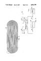
- FIG. 4 is a perspective illustration of the adjacent optical segments of FIG. 2 detailing electical coils used with an inductive displacement sensor provided according to the present invention.
- FIG. 5 is an illustration in plan of an inductive coil of FIG. 4.
- FIG. 6 is a simplified schematic illustration of an electrical control circuit used with an inductive displacement sensor provided according to the present invention.
- FIG. 1 there is shown in perspective a simplified schematic illustration of a segmented mirror 10 which is exemplary of active optical elements that employ the present invention.
- the mirror 10 is described and claimed in the commonly owned copending U.S. patent application entitled “Extendable Large Aperture Phased Array Mirror System", Ser. No. 114,540 and incorporated herein by reference.
- the mirror is comprised of a plurality of cooperative movable segments such as adjacent segments 12 and 14. As detailed hereinafter each segment, in cooperation with its adjacent segments, has a plurality of inductive displacement sensors associated with it and embodying the present invention.
- segments 12 and 14 are seen to comprise first mirror surfaces 16 and 18, respectively, and a plurality of secondary side faces or surfaces perpendicular thereto.
- these optical segments are hexagonal in shape and are configured to substantially abut along juxtaposed side surfaces such as the respective surfaces 20 and 22 of segments 12 and 14 shown in section in FIG. 3.
- Each segment is independently movable along a displacement axis 24 or 26 by the use of actuators, such as the illustrated actuators 27, 28 and 29, not part of the present invention.
- An inductive displacement sensor comprises two pairs of inductive coils disposed on the two opposed surfaces of two adjacent optical segments as evident from FIG. 4.
- first primary coils 30 and 31 are spaced along an axis 32 substantially on opposite sides thereof generally perpendicular to the axis 26 of segment displacement.
- Each coil is embedded in or etched into the side surface 33 of segment 12.
- Each coil 30 and 31 is substantially planar and located in a plane approximately parallel to the side surface 33.
- FIG. 5 is a detailed illustration clearly showing the oblong planar wound structure of coil 30. Although shown with an oblong geometry, those skilled in the art will understand that other equivalent geometries may be substituted.
- secondary coils 34 and 36 which have approximately the same parameters as primary coils 30 and 31. These secondary coils are disposed on an opposed side surface of an adjacent segment, not shown.
- the two coils of the second coil pair are also spaced from one another along a reference axis parallel to the first coil pair reference axis so that each is located generally opposite to and inductively coupled with an associated one of the coils of the first pair.
- the two coils of the second pair are also displaced respectively in opposite directions from the second coil pair reference axis but in the way opposite to that of the first pair of coils.
- the secondary coils are displaced on the opposed side surface along an axis parallel to axis 32 in an alternating manner with respect to the primary coils and are positioned to partially overlap a respective one of the magnetic fluxes extending from primary coils.
- a first set of inductively coupled coils is formed from one of the first primary coils with a corresponding one of the secondary coils.
- primary coil 30 and secondary coil 34 form a first set of inductively coupled coils while primary coils 31 and secondary coil 36 form a second inductively coupled coil set.
- the second set of inductively coupled coils moves toward greater coupling and the first set of inductively coupled coils moves toward lesser coupling.
- the first inductively coupled coiled set is moved toward increased coupling while the second coil set is moved towards a lesser coupling.
- FIG. 6 shows in simplified schematic format, the circuit 38 of the inductive displacement sensor of FIG. 4.
- Symbols 40 and 42 illustrate the inductance of coils 30 and 31, respectively.
- symbols 44 and 45 represent the inductance of coils 34 and 36, respectively.
- Symbols 46 and 47 correspond to the respective capacitance associated with coils 44 and 45, respectively which may be the capacitance of that coil or a discrete capacitive element.
- Circuit 38 includes a conventional oscillator 48 with series resistance 50 and capacitance 52.
- circuit 38 is resonant.
- One secondary coil and its associated capacitance is tuned slightly above the resonance frequency while the other secondary coil and its associated capacitance is tuned slightly below resonance.
- the primary coils 30 and 31 inductively couple to secondary coils 34 and 36 on the opposed surface of the adjacent segment as detailed hereinabove. Any relative motion along the displacement axis between the opposed segment surfaces perturbs the resonant circuit signal by changing the complex impedance of the circuit which produces a change in the phase relationship between the circuit signal's current and voltage.
- This phase change is sensed by phase detector 54 and is used to produce a feedback control signal for the segment actuators (not shown).
- the phase change is linearly related to the displacement between the segment edges.
- a key feature of an inductive displacement sensor provided, according to the present invention, is that the tuned secondary coils are completely passive, and therefore no wires or other apparatus need bridge the gap between segments.
- Existing capacitive displacement sensors, such as the Keck sensor described hereinabove, have the disadvantage of mechanical and electrical coupling between adjacent segments.
- a signal null point of an inductive displacement sensor provided according to the present invention is defined by the plane of symmetry where the primary coils equally couple with both of the secondary coils. Since the impedance of the secondary coils can be tuned, the circuit 38 can be made both extremely sensitive and linear. Moreover, the null point is insensitive to changes in segment gap or temperature.
- the necessary signal conditioning electronics is of very low complexity, and can be easily implemented with well known low power CMOS technology. It is preferred that the circuit 38 be conventionally fabricated to allow for local positioning directly with the segment.
- An inductive displacement sensor provided according to the present invention can resolve 10 nanometer misalignment of adjacent segment surface edges with accuracy at the null point of at least 50 nanometers. Moreover, the full measurement range is at least 200 microns, and has a frequency response of at least 5 kilohertz.
- adjacent side surfaces of each segment will possess primary and secondary coils configured as described herinabove. Consequently, each segment will have three primary coil pairs and three secondary coil pairs formed on alternate side surfaces of a segment.
- an inductive displacement sensor system therefore comprises three inductive sensors whose primary coils are disposed on alternate segment side surfaces and whose oscillator circuitry can be locally configured with the segment shown generally at 54, FIG. 3, or remotely located.
- the segment sensor corresponding secondary coil pairs are disposed on respective side surfaces of adjacent segments.
Abstract
Description
Claims (10)
Priority Applications (1)
| Application Number | Priority Date | Filing Date | Title |
|---|---|---|---|
| US07/114,436 US4816759A (en) | 1987-10-28 | 1987-10-28 | Inductive sensor for detecting displacement of adjacent surfaces |
Applications Claiming Priority (1)
| Application Number | Priority Date | Filing Date | Title |
|---|---|---|---|
| US07/114,436 US4816759A (en) | 1987-10-28 | 1987-10-28 | Inductive sensor for detecting displacement of adjacent surfaces |
Publications (1)
| Publication Number | Publication Date |
|---|---|
| US4816759A true US4816759A (en) | 1989-03-28 |
Family
ID=22355198
Family Applications (1)
| Application Number | Title | Priority Date | Filing Date |
|---|---|---|---|
| US07/114,436 Expired - Lifetime US4816759A (en) | 1987-10-28 | 1987-10-28 | Inductive sensor for detecting displacement of adjacent surfaces |
Country Status (1)
| Country | Link |
|---|---|
| US (1) | US4816759A (en) |
Cited By (46)
| Publication number | Priority date | Publication date | Assignee | Title |
|---|---|---|---|---|
| US4906924A (en) * | 1986-11-04 | 1990-03-06 | Renishaw Plc | Linear variable displacement transducers including phase shifting series connected coils |
| EP0369393A2 (en) * | 1988-11-18 | 1990-05-23 | Advanced Interconnection Technology, Inc. | Precision work positioning by electrical measurement |
| US4943771A (en) * | 1989-05-19 | 1990-07-24 | The United States Of America As Represented By The Secretary Of The Air Force | Differential eddy current sensor measuring apparatus for use with movable mirror segments |
| US5078010A (en) * | 1989-09-06 | 1992-01-07 | Emhart Inc. | Inductance level sensing device |
| US5109349A (en) * | 1990-01-23 | 1992-04-28 | Kaman Aerospace Corporation | Actively controlled segmented mirror |
| US5113064A (en) * | 1991-03-06 | 1992-05-12 | The United States Of America As Represented By The Administrator Of The National Aeronautics And Space Administration | Method and apparatus for phasing segmented mirror arrays |
| US5172298A (en) * | 1990-01-09 | 1992-12-15 | Honda Giken Kogyo Kabushiki Kaisha | Electromagnetic actuator |
| US5221896A (en) * | 1991-02-18 | 1993-06-22 | Kawasaki Jukogyo Kabushiki Kaisha | Position sensor arrangement for detecting a signal after a time delay from the zero crossing of the ac power source |
| US5233294A (en) * | 1990-05-03 | 1993-08-03 | Alessandro Dreoni | Inductive proximity sensor and position transducer with a passive scale |
| US5291782A (en) * | 1993-02-16 | 1994-03-08 | Taylor Howard E | Eddy current position sensor |
| US5541510A (en) * | 1995-04-06 | 1996-07-30 | Kaman Instrumentation Corporation | Multi-Parameter eddy current measuring system with parameter compensation technical field |
| US5617023A (en) * | 1995-02-02 | 1997-04-01 | Otis Elevator Company | Industrial contactless position sensor |
| US5640472A (en) * | 1995-06-07 | 1997-06-17 | United Technologies Corporation | Fiber optic sensor for magnetic bearings |
| DE19738836A1 (en) * | 1997-09-05 | 1999-03-11 | Hella Kg Hueck & Co | Inductive angle sensor |
| DE19738841A1 (en) * | 1997-09-05 | 1999-03-11 | Hella Kg Hueck & Co | Inductive angle sensor |
| US5886519A (en) * | 1997-01-29 | 1999-03-23 | Mitutoyo Corporation | Multi-scale induced current absolute position transducer |
| US5973494A (en) * | 1996-05-13 | 1999-10-26 | Mitutoyo Corporation | Electronic caliper using a self-contained, low power inductive position transducer |
| US6002250A (en) * | 1996-05-13 | 1999-12-14 | Mitutoyo Corporation | Electronic linear scale using a self-contained, low-power inductive position transducer |
| US6011389A (en) * | 1995-05-16 | 2000-01-04 | Mitutoyo Corporation | Induced current position transducer having a low power electronic circuit |
| EP1248076A1 (en) * | 2001-07-30 | 2002-10-09 | Esec Trading S.A. | Inductive Sensor for determining the position of a metallic workpiece |
| US6580262B1 (en) * | 1999-01-13 | 2003-06-17 | Elektro-Mechanik Gmbh | Method and device for measuring the position of a metal strip |
| US6656135B2 (en) * | 2000-05-01 | 2003-12-02 | Southwest Research Institute | Passive and wireless displacement measuring device |
| US20040004725A1 (en) * | 2002-03-28 | 2004-01-08 | Dimitry Gorinevsky | Measurement system for electromagnetic radiation structure |
| US7050161B1 (en) | 2003-08-06 | 2006-05-23 | The United States Of America As Represented By The Administration Of The National Aeronautics And Space Administration | Global radius of curvature estimation and control system for segmented mirrors |
| US20060125472A1 (en) * | 2002-10-16 | 2006-06-15 | Tt Electronics Technology Limited | Position sensing apparatus and method |
| FR2888319A1 (en) * | 2005-07-07 | 2007-01-12 | Nanotec Solution Soc Civ Ile | METHOD FOR NON-CONTACT MEASUREMENT OF RELATIVE DISPLACEMENT OR RELATIVE POSITIONING OF A FIRST OBJECT IN RELATION TO A SECOND OBJECT INDUCINGLY. |
| US20080116883A1 (en) * | 2006-11-22 | 2008-05-22 | Stefan Ruehl | Inductive sensor for sensing of two coupling elements |
| ES2307450A1 (en) * | 2008-04-16 | 2008-11-16 | Universidad Politecnica De Madrid | Magnetic device position sensor (Machine-translation by Google Translate, not legally binding) |
| US20090282894A1 (en) * | 2008-05-16 | 2009-11-19 | Honeywell International, Inc. | Inertial sensor misalignment and compensation |
| US20090282893A1 (en) * | 2008-05-16 | 2009-11-19 | Honeywell International, Inc. | Inertial sensor misalignment and compensation |
| US20100001718A1 (en) * | 2004-12-20 | 2010-01-07 | Mark Anthony Howard | Inductive position sensor |
| US20100077860A1 (en) * | 2008-09-30 | 2010-04-01 | Honeywell International Inc. | Systems and methods for integrated isolator and transducer components in an inertial sensor |
| WO2010099770A1 (en) | 2009-03-02 | 2010-09-10 | Micro-Epsilon Messtechnik Gmbh & Co. Kg | Position sensor |
| GB2472275A (en) * | 2009-07-31 | 2011-02-02 | Oxford Rf Sensors Ltd | Proximity sensor |
| CN102877897A (en) * | 2011-07-15 | 2013-01-16 | 阿特拉斯·科普柯能源有限公司 | Turbo machine with magnetic bearings |
| DE102012212064A1 (en) * | 2012-07-11 | 2014-01-16 | Carl Zeiss Smt Gmbh | Lithographic plant with segmented mirror |
| US20140157897A1 (en) * | 2012-12-12 | 2014-06-12 | Raytheon Company | Hung Mass Accelerometer With Differential Eddy Current Sensing |
| WO2014140298A2 (en) * | 2013-03-14 | 2014-09-18 | Carl Zeiss Smt Gmbh | Position sensor, sensor arrangement and lithography apparatus comprising position sensor |
| US9784759B2 (en) | 2015-11-16 | 2017-10-10 | Raytheon Company | Thermally insensitive open-loop hung mass accelerometer with differential Eddy current sensing |
| WO2017182040A1 (en) * | 2016-04-21 | 2017-10-26 | Micro-Epsilon Messtechnik Gmbh & Co. Kg | Measuring assembly for the contactless measurement of a relative movement or a relative position and method |
| US10024880B2 (en) | 2016-05-21 | 2018-07-17 | Raytheon Company | Athermal hung mass accelerometer with reduced sensitivity to longitudinal temperature gradients |
| CN109728706A (en) * | 2017-10-31 | 2019-05-07 | 三星电机株式会社 | Actuator |
| US10816316B2 (en) | 2018-08-07 | 2020-10-27 | Raytheon Company | Inductive sensor device with local analog-to-digital converter |
| US11054395B2 (en) | 2018-03-07 | 2021-07-06 | Raytheon Company | Inductive sensor device with reference sensor |
| US20210310829A1 (en) * | 2020-04-02 | 2021-10-07 | Lg Electronics Inc. | Displacement sensor |
| RU2782151C1 (en) * | 2022-02-07 | 2022-10-21 | Общество с ограниченной ответственностью "МДРАЙВ" | Inductive position transmitter with active moving part |
Citations (7)
| Publication number | Priority date | Publication date | Assignee | Title |
|---|---|---|---|---|
| US2438197A (en) * | 1942-12-31 | 1948-03-23 | Hazeltine Research Inc | Phase-selective variable-frequency oscillatory system |
| US3500373A (en) * | 1966-05-06 | 1970-03-10 | Nat Bank Of North America The | Method and apparatus for article theft detection |
| US3526886A (en) * | 1968-03-26 | 1970-09-01 | Westinghouse Air Brake Co | Precision location detector |
| US3721821A (en) * | 1970-12-14 | 1973-03-20 | Abex Corp | Railway wheel sensor |
| US4618822A (en) * | 1984-04-18 | 1986-10-21 | Position Orientation Systems, Ltd. | Displacement sensing device utilizing adjustable tuned circuit |
| US4638250A (en) * | 1984-01-30 | 1987-01-20 | Fiscint, Inc. | Contactless position sensor with coreless coil coupling component |
| US4663589A (en) * | 1985-02-11 | 1987-05-05 | Sensor Technologies, Inc. | Displacement sensor having multiplexed dual tank circuits |
-
1987
- 1987-10-28 US US07/114,436 patent/US4816759A/en not_active Expired - Lifetime
Patent Citations (7)
| Publication number | Priority date | Publication date | Assignee | Title |
|---|---|---|---|---|
| US2438197A (en) * | 1942-12-31 | 1948-03-23 | Hazeltine Research Inc | Phase-selective variable-frequency oscillatory system |
| US3500373A (en) * | 1966-05-06 | 1970-03-10 | Nat Bank Of North America The | Method and apparatus for article theft detection |
| US3526886A (en) * | 1968-03-26 | 1970-09-01 | Westinghouse Air Brake Co | Precision location detector |
| US3721821A (en) * | 1970-12-14 | 1973-03-20 | Abex Corp | Railway wheel sensor |
| US4638250A (en) * | 1984-01-30 | 1987-01-20 | Fiscint, Inc. | Contactless position sensor with coreless coil coupling component |
| US4618822A (en) * | 1984-04-18 | 1986-10-21 | Position Orientation Systems, Ltd. | Displacement sensing device utilizing adjustable tuned circuit |
| US4663589A (en) * | 1985-02-11 | 1987-05-05 | Sensor Technologies, Inc. | Displacement sensor having multiplexed dual tank circuits |
Cited By (76)
| Publication number | Priority date | Publication date | Assignee | Title |
|---|---|---|---|---|
| US4906924A (en) * | 1986-11-04 | 1990-03-06 | Renishaw Plc | Linear variable displacement transducers including phase shifting series connected coils |
| EP0369393A3 (en) * | 1988-11-18 | 1993-10-20 | Advanced Interconnection Technology, Inc. | Precision work positioning by electrical measurement |
| EP0369393A2 (en) * | 1988-11-18 | 1990-05-23 | Advanced Interconnection Technology, Inc. | Precision work positioning by electrical measurement |
| US4943771A (en) * | 1989-05-19 | 1990-07-24 | The United States Of America As Represented By The Secretary Of The Air Force | Differential eddy current sensor measuring apparatus for use with movable mirror segments |
| US5078010A (en) * | 1989-09-06 | 1992-01-07 | Emhart Inc. | Inductance level sensing device |
| US5172298A (en) * | 1990-01-09 | 1992-12-15 | Honda Giken Kogyo Kabushiki Kaisha | Electromagnetic actuator |
| US5109349A (en) * | 1990-01-23 | 1992-04-28 | Kaman Aerospace Corporation | Actively controlled segmented mirror |
| US5233294A (en) * | 1990-05-03 | 1993-08-03 | Alessandro Dreoni | Inductive proximity sensor and position transducer with a passive scale |
| US5221896A (en) * | 1991-02-18 | 1993-06-22 | Kawasaki Jukogyo Kabushiki Kaisha | Position sensor arrangement for detecting a signal after a time delay from the zero crossing of the ac power source |
| US5113064A (en) * | 1991-03-06 | 1992-05-12 | The United States Of America As Represented By The Administrator Of The National Aeronautics And Space Administration | Method and apparatus for phasing segmented mirror arrays |
| US5291782A (en) * | 1993-02-16 | 1994-03-08 | Taylor Howard E | Eddy current position sensor |
| US5617023A (en) * | 1995-02-02 | 1997-04-01 | Otis Elevator Company | Industrial contactless position sensor |
| US5541510A (en) * | 1995-04-06 | 1996-07-30 | Kaman Instrumentation Corporation | Multi-Parameter eddy current measuring system with parameter compensation technical field |
| US6011389A (en) * | 1995-05-16 | 2000-01-04 | Mitutoyo Corporation | Induced current position transducer having a low power electronic circuit |
| US5640472A (en) * | 1995-06-07 | 1997-06-17 | United Technologies Corporation | Fiber optic sensor for magnetic bearings |
| US6002250A (en) * | 1996-05-13 | 1999-12-14 | Mitutoyo Corporation | Electronic linear scale using a self-contained, low-power inductive position transducer |
| US5973494A (en) * | 1996-05-13 | 1999-10-26 | Mitutoyo Corporation | Electronic caliper using a self-contained, low power inductive position transducer |
| US5886519A (en) * | 1997-01-29 | 1999-03-23 | Mitutoyo Corporation | Multi-scale induced current absolute position transducer |
| US6236199B1 (en) | 1997-09-05 | 2001-05-22 | Hella Kg Hueck & Co. | Inductive angle sensor |
| DE19738836A1 (en) * | 1997-09-05 | 1999-03-11 | Hella Kg Hueck & Co | Inductive angle sensor |
| US6255810B1 (en) | 1997-09-05 | 2001-07-03 | Hella Kg Hueck & Co. | Inductive angle sensor having coupled oscillators with similar inductive response |
| DE19738841A1 (en) * | 1997-09-05 | 1999-03-11 | Hella Kg Hueck & Co | Inductive angle sensor |
| US6580262B1 (en) * | 1999-01-13 | 2003-06-17 | Elektro-Mechanik Gmbh | Method and device for measuring the position of a metal strip |
| US20040068205A1 (en) * | 2000-05-01 | 2004-04-08 | Southwest Research Institute | Passive and wireless displacement measuring device using parallel sensors |
| US6656135B2 (en) * | 2000-05-01 | 2003-12-02 | Southwest Research Institute | Passive and wireless displacement measuring device |
| EP1248076A1 (en) * | 2001-07-30 | 2002-10-09 | Esec Trading S.A. | Inductive Sensor for determining the position of a metallic workpiece |
| US7038792B2 (en) | 2002-03-28 | 2006-05-02 | Honeywell International Inc. | Measurement system for electromagnetic radiation structure |
| US7012271B2 (en) | 2002-03-28 | 2006-03-14 | Honeywell International Inc. | Electromagnetic radiation structure control system |
| US20040004725A1 (en) * | 2002-03-28 | 2004-01-08 | Dimitry Gorinevsky | Measurement system for electromagnetic radiation structure |
| US20040021098A1 (en) * | 2002-03-28 | 2004-02-05 | Dimitry Gorinevsky | Electromagnetic radiation structure control system |
| US20060125472A1 (en) * | 2002-10-16 | 2006-06-15 | Tt Electronics Technology Limited | Position sensing apparatus and method |
| US7298137B2 (en) * | 2002-10-16 | 2007-11-20 | Tt Electronics Technology Limited | Position sensing apparatus and method |
| US7050161B1 (en) | 2003-08-06 | 2006-05-23 | The United States Of America As Represented By The Administration Of The National Aeronautics And Space Administration | Global radius of curvature estimation and control system for segmented mirrors |
| US20100001718A1 (en) * | 2004-12-20 | 2010-01-07 | Mark Anthony Howard | Inductive position sensor |
| US9945653B2 (en) | 2004-12-20 | 2018-04-17 | Mark Anthony Howard | Inductive position sensor |
| WO2007006910A1 (en) | 2005-07-07 | 2007-01-18 | Nanotec Solution | Inductive non-contact measurement of a relative movement or relative positioning of a first object relative to a second object |
| US20090140729A1 (en) * | 2005-07-07 | 2009-06-04 | Didier Roziere | Inductive non-contact measurement of a relative movement or relative positioning of a first object relative to a second object |
| FR2888319A1 (en) * | 2005-07-07 | 2007-01-12 | Nanotec Solution Soc Civ Ile | METHOD FOR NON-CONTACT MEASUREMENT OF RELATIVE DISPLACEMENT OR RELATIVE POSITIONING OF A FIRST OBJECT IN RELATION TO A SECOND OBJECT INDUCINGLY. |
| US8159213B2 (en) * | 2005-07-07 | 2012-04-17 | Nanotec Solution | Inductive non-contact measurement of a relative movement or relative positioning of a first object relative to a second object |
| US20080116883A1 (en) * | 2006-11-22 | 2008-05-22 | Stefan Ruehl | Inductive sensor for sensing of two coupling elements |
| ES2307450A1 (en) * | 2008-04-16 | 2008-11-16 | Universidad Politecnica De Madrid | Magnetic device position sensor (Machine-translation by Google Translate, not legally binding) |
| US20090282894A1 (en) * | 2008-05-16 | 2009-11-19 | Honeywell International, Inc. | Inertial sensor misalignment and compensation |
| US20090282893A1 (en) * | 2008-05-16 | 2009-11-19 | Honeywell International, Inc. | Inertial sensor misalignment and compensation |
| EP2131151A1 (en) * | 2008-05-16 | 2009-12-09 | Honeywell International Inc. | Inertial sensor misalignment and compensation |
| EP2120013A3 (en) * | 2008-05-16 | 2009-12-09 | Honeywell International Inc. | Inertial sensor misalignment and compensation |
| US8061181B2 (en) | 2008-05-16 | 2011-11-22 | Honeywell International Inc. | Inertial sensor misalignment and compensation |
| US8047047B2 (en) | 2008-05-16 | 2011-11-01 | Honeywell International Inc. | Inertial sensor misalignment and compensation |
| US20100077860A1 (en) * | 2008-09-30 | 2010-04-01 | Honeywell International Inc. | Systems and methods for integrated isolator and transducer components in an inertial sensor |
| US8941389B2 (en) | 2009-03-02 | 2015-01-27 | Micro-Epsilon Messtechnik Gmbh & Co. Kg | Position sensor |
| DE102009022992A1 (en) | 2009-03-02 | 2010-10-07 | Micro-Epsilon Messtechnik Gmbh & Co. Kg | position sensor |
| WO2010099770A1 (en) | 2009-03-02 | 2010-09-10 | Micro-Epsilon Messtechnik Gmbh & Co. Kg | Position sensor |
| JP2012519287A (en) * | 2009-03-02 | 2012-08-23 | マイクロ−エプシロン・メステヒニク・ゲーエムベーハー・ウント・コンパニー・カー・ゲー | Position sensor |
| EP2284478A1 (en) * | 2009-07-31 | 2011-02-16 | Oxford RF Sensors Ltd | Proximity sensor |
| GB2472275A (en) * | 2009-07-31 | 2011-02-02 | Oxford Rf Sensors Ltd | Proximity sensor |
| WO2011012843A1 (en) * | 2009-07-31 | 2011-02-03 | Oxford Rf Sensors Limited | Proximity sensor |
| CN102877897A (en) * | 2011-07-15 | 2013-01-16 | 阿特拉斯·科普柯能源有限公司 | Turbo machine with magnetic bearings |
| CN102877897B (en) * | 2011-07-15 | 2015-10-21 | 阿特拉斯·科普柯能源有限公司 | Turbo machine |
| JP2015529839A (en) * | 2012-07-11 | 2015-10-08 | カール・ツァイス・エスエムティー・ゲーエムベーハー | Lithographic apparatus having a segmented mirror |
| US9846375B2 (en) | 2012-07-11 | 2017-12-19 | Carl Zeiss Smt Gmbh | Lithography apparatus with segmented mirror |
| DE102012212064A1 (en) * | 2012-07-11 | 2014-01-16 | Carl Zeiss Smt Gmbh | Lithographic plant with segmented mirror |
| US20140157897A1 (en) * | 2012-12-12 | 2014-06-12 | Raytheon Company | Hung Mass Accelerometer With Differential Eddy Current Sensing |
| WO2014092825A1 (en) | 2012-12-12 | 2014-06-19 | Raytheon Company | Hung mass accelerometer with differential eddy current sensing |
| US9121865B2 (en) * | 2012-12-12 | 2015-09-01 | Raytheon Company | Hung mass accelerometer with differential Eddy current sensing |
| WO2014140298A3 (en) * | 2013-03-14 | 2014-12-18 | Carl Zeiss Smt Gmbh | Position sensor, sensor arrangement and lithography apparatus comprising position sensor |
| WO2014140298A2 (en) * | 2013-03-14 | 2014-09-18 | Carl Zeiss Smt Gmbh | Position sensor, sensor arrangement and lithography apparatus comprising position sensor |
| US9784759B2 (en) | 2015-11-16 | 2017-10-10 | Raytheon Company | Thermally insensitive open-loop hung mass accelerometer with differential Eddy current sensing |
| WO2017182040A1 (en) * | 2016-04-21 | 2017-10-26 | Micro-Epsilon Messtechnik Gmbh & Co. Kg | Measuring assembly for the contactless measurement of a relative movement or a relative position and method |
| US10024880B2 (en) | 2016-05-21 | 2018-07-17 | Raytheon Company | Athermal hung mass accelerometer with reduced sensitivity to longitudinal temperature gradients |
| CN109728706A (en) * | 2017-10-31 | 2019-05-07 | 三星电机株式会社 | Actuator |
| KR20190048540A (en) * | 2017-10-31 | 2019-05-09 | 삼성전기주식회사 | Actuator of camera module |
| US11042005B2 (en) | 2017-10-31 | 2021-06-22 | Samsung Electro-Mechanics Co., Ltd. | Actuator of camera module |
| US11054395B2 (en) | 2018-03-07 | 2021-07-06 | Raytheon Company | Inductive sensor device with reference sensor |
| US10816316B2 (en) | 2018-08-07 | 2020-10-27 | Raytheon Company | Inductive sensor device with local analog-to-digital converter |
| US20210310829A1 (en) * | 2020-04-02 | 2021-10-07 | Lg Electronics Inc. | Displacement sensor |
| US11920959B2 (en) * | 2020-04-02 | 2024-03-05 | Lg Electronics Inc. | Displacement sensor having a coil structure, a shield member and a housing |
| RU2782151C1 (en) * | 2022-02-07 | 2022-10-21 | Общество с ограниченной ответственностью "МДРАЙВ" | Inductive position transmitter with active moving part |
Similar Documents
| Publication | Publication Date | Title |
|---|---|---|
| US4816759A (en) | Inductive sensor for detecting displacement of adjacent surfaces | |
| US6629461B2 (en) | Biased rotatable combdrive actuator methods | |
| Heerens | Application of capacitance techniques in sensor design | |
| EP0774681A1 (en) | Electromagnetic actuator | |
| US20010050801A1 (en) | Biased rotatable combdrive devices and methods | |
| US5612815A (en) | Optical device for optomechanical application | |
| US6310990B1 (en) | Tunable optical structure featuring feedback control | |
| US6612029B2 (en) | Multi-layer, self-aligned vertical combdrive electrostatic actuators and fabrication methods | |
| US4567771A (en) | Optical accelerometer | |
| EP0668490A2 (en) | Electrically tunable fabry-perot interferometer produced by surface micromechanical techniques for use in optical material analysis | |
| EP1446979B1 (en) | Optical displacement sensor element | |
| US9291444B2 (en) | Light reflection mechanism, optical interferometer and spectrometric analyzer | |
| JPH0694425A (en) | Optical integrated distortion interferometer | |
| EP0745858B1 (en) | Acceleration sensor | |
| JPH06230023A (en) | Displacement detecting sensor | |
| JP2006201014A (en) | Optical waveguide type sensor and its manufacturing method | |
| US5111694A (en) | Accelerometer with rebalance coil stress isolation | |
| US5377285A (en) | Technique for making ultrastable ring resonators and lasers | |
| Sydenham | Microdisplacement transducers | |
| WO2003029753A2 (en) | Modular non-contacting position sensor | |
| US20020030486A1 (en) | High sensitivity displacement measuring device using linear variable differential transformer | |
| US4918987A (en) | Laser accelerometer | |
| US4943771A (en) | Differential eddy current sensor measuring apparatus for use with movable mirror segments | |
| JPH0836122A (en) | Waveguide coupling module | |
| RU1784837C (en) | Angle displacement two-co-ordinates converter |
Legal Events
| Date | Code | Title | Description |
|---|---|---|---|
| AS | Assignment |
Owner name: KAMAN CORPORATION, OLD WINDSOR RAOD, BLOOMFIELD, C Free format text: ASSIGNMENT OF ASSIGNORS INTEREST.;ASSIGNORS:AMES, GREGORY H.;HOLMGREN, WILLIAM A.;WIDENER, A. LEE;REEL/FRAME:004832/0898 Effective date: 19871130 Owner name: KAMAN CORPORATION,CONNECTICUT Free format text: ASSIGNMENT OF ASSIGNORS INTEREST;ASSIGNORS:AMES, GREGORY H.;HOLMGREN, WILLIAM A.;WIDENER, A. LEE;REEL/FRAME:004832/0898 Effective date: 19871130 |
|
| AS | Assignment |
Owner name: KAMAN INSTRUMENTATION CORPORATION, 1500 GARDEN OF Free format text: ASSIGNMENT OF ASSIGNORS INTEREST.;ASSIGNOR:KAMAN CORPORATION;REEL/FRAME:004945/0563 Effective date: 19880617 Owner name: KAMAN INSTRUMENTATION CORPORATION, COLORADO Free format text: ASSIGNMENT OF ASSIGNORS INTEREST;ASSIGNOR:KAMAN CORPORATION;REEL/FRAME:004945/0563 Effective date: 19880617 |
|
| STCF | Information on status: patent grant |
Free format text: PATENTED CASE |
|
| CC | Certificate of correction | ||
| FEPP | Fee payment procedure |
Free format text: PAYOR NUMBER ASSIGNED (ORIGINAL EVENT CODE: ASPN); ENTITY STATUS OF PATENT OWNER: LARGE ENTITY |
|
| FPAY | Fee payment |
Year of fee payment: 4 |
|
| FPAY | Fee payment |
Year of fee payment: 8 |
|
| AS | Assignment |
Owner name: KAMAN INSTRUMENTATION CORPORATION, COLORADO Free format text: ASSIGNMENT OF ASSIGNORS INTEREST;ASSIGNOR:KAMAN CORPORATION;REEL/FRAME:009453/0226 Effective date: 19980904 |
|
| FPAY | Fee payment |
Year of fee payment: 12 |
|
| AS | Assignment |
Owner name: KAMAN AEROSPACE CORPORATION, CONNECTICUT Free format text: MERGER;ASSIGNOR:KAMAN INSTRUMENTATION CORPORATION;REEL/FRAME:011170/0930 Effective date: 19990913 |