US4809015A - Continuous ink jet printer having modular print head assembly - Google Patents
Continuous ink jet printer having modular print head assembly Download PDFInfo
- Publication number
- US4809015A US4809015A US07/168,094 US16809488A US4809015A US 4809015 A US4809015 A US 4809015A US 16809488 A US16809488 A US 16809488A US 4809015 A US4809015 A US 4809015A
- Authority
- US
- United States
- Prior art keywords
- module
- print head
- nest
- droplet
- nest assembly
- Prior art date
- Legal status (The legal status is an assumption and is not a legal conclusion. Google has not performed a legal analysis and makes no representation as to the accuracy of the status listed.)
- Expired - Lifetime
Links
Images


Classifications
-
- B—PERFORMING OPERATIONS; TRANSPORTING
- B41—PRINTING; LINING MACHINES; TYPEWRITERS; STAMPS
- B41J—TYPEWRITERS; SELECTIVE PRINTING MECHANISMS, i.e. MECHANISMS PRINTING OTHERWISE THAN FROM A FORME; CORRECTION OF TYPOGRAPHICAL ERRORS
- B41J2/00—Typewriters or selective printing mechanisms characterised by the printing or marking process for which they are designed
- B41J2/005—Typewriters or selective printing mechanisms characterised by the printing or marking process for which they are designed characterised by bringing liquid or particles selectively into contact with a printing material
- B41J2/01—Ink jet
- B41J2/015—Ink jet characterised by the jet generation process
- B41J2/02—Ink jet characterised by the jet generation process generating a continuous ink jet
-
- B—PERFORMING OPERATIONS; TRANSPORTING
- B41—PRINTING; LINING MACHINES; TYPEWRITERS; STAMPS
- B41J—TYPEWRITERS; SELECTIVE PRINTING MECHANISMS, i.e. MECHANISMS PRINTING OTHERWISE THAN FROM A FORME; CORRECTION OF TYPOGRAPHICAL ERRORS
- B41J2/00—Typewriters or selective printing mechanisms characterised by the printing or marking process for which they are designed
- B41J2/005—Typewriters or selective printing mechanisms characterised by the printing or marking process for which they are designed characterised by bringing liquid or particles selectively into contact with a printing material
- B41J2/01—Ink jet
- B41J2/17—Ink jet characterised by ink handling
- B41J2/175—Ink supply systems ; Circuit parts therefor
-
- B—PERFORMING OPERATIONS; TRANSPORTING
- B41—PRINTING; LINING MACHINES; TYPEWRITERS; STAMPS
- B41J—TYPEWRITERS; SELECTIVE PRINTING MECHANISMS, i.e. MECHANISMS PRINTING OTHERWISE THAN FROM A FORME; CORRECTION OF TYPOGRAPHICAL ERRORS
- B41J2/00—Typewriters or selective printing mechanisms characterised by the printing or marking process for which they are designed
- B41J2/005—Typewriters or selective printing mechanisms characterised by the printing or marking process for which they are designed characterised by bringing liquid or particles selectively into contact with a printing material
- B41J2/01—Ink jet
- B41J2/135—Nozzles
- B41J2/14—Structure thereof only for on-demand ink jet heads
- B41J2002/14362—Assembling elements of heads
Definitions
- the present invention relates to improvements in continuous ink jet printer systems and more particularly to modular constructions whereby the droplet stream generator subsystem, the droplet charging subsystem, the droplet catching subsystem and droplet path air guide subsystem of such printer systems are easily and cleanly removable as a unit.
- ink is supplied under pressure to the orifice cavity of a resonator body and ejects as continuous streams from an orifice plate aimed toward a print zone.
- the resonator body is vibrated to cause the ink streams to break up into uniformly sized and shaped droplets.
- a charge plate subsystem is located proximate the stream break-up point and droplets are selectively charged if intended to be non-printing ones.
- the charged, non-printing drops are deflected to a catcher subassembly which routes them back to the main ink supply. Uncharged drops pass on to the print zone.
- U.S. Pat. No. 4,623,897 discloses an embodiment of continuous ink jet printer wherein the above-noted components are constructed as a traversing print head assembly, e.g. for printing successive lines of information with 64 orifices and related charge plate elements.
- This print head assembly also incorporates an air guide member located adjacent the catcher for cooperating to prevent dust from reaching the charge plate/orifice plate region.
- One important objective of the present invention is to obviate the above-noted problems that are connected with the replacement of a continuous ink jet print head assembly.
- One advantage of the present invention is the simplicity by which a customer/user can effect replacement of such assembly, accurately and in a very brief time.
- Another important advantage is that replacement can be effected without any ink leaking from the printer or removed print head assembly.
- a modular print head assembly connection system that comprises (i) a print head assembly nest attached to the printer apparatus and including ink supply line and return line ports, a catcher return line port, resonator and charge plate power supply terminals and means for supporting and accurately positioning a print head assembly module, (ii) a print head assembly module including ink supply and return line coupling means each having a check valve means constructed for engage-opening cooperation with a respective port of the nest, catcher return line coupling means, charge plate and resonator connector means constructed to interfit with the respective terminals of the nest and index means for cooperating with the support and positioning means of the nest, and (iii) camming means mounted on the assembly nest and movable to force a module inserted into the nest into operative relation with the ink lines coupled, the check valves open and the resonator and charge plate connector means electrically coupled to their respective power supply terminals.
- FIG. 1 is a perspective view of a continuous, traversing head, ink jet printer incorporating one embodiment of the present invention
- FIG. 2 is a fluid flow diagram of one ink recirculation system of the FIG. 1 printer
- FIG. 3 is an exploded perspective view of one preferred print head assembly module in accord with the present invention.
- FIGS. 4 and 5 are respectively exploded and assembled perspective views of one preferred printer nest construction adapted for cooperation with the FIG. 3 module;
- FIG. 6 is a front view of the FIG. 5 nest construction
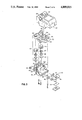
- FIG. 7 is a top view of the FIG. 5 nest construction
- FIG. 8 is a side view of the FIG. 5 nest construction.
- FIGS. 9 and 10 are respectively enlarged exploded and assembled perspective views showing details of the check valve/printer port construction of the FIGS. 3-8 system.
- FIG. 1 illustrates schematically an exemplary ink jet printing apparatus 1 employing one embodiment of the present invention.
- the apparatus 1 comprises a paper feed and return section 2 from which sheets are transported into and out of operative relation on rotatable cylinder 3.
- the detail structure of the sheet handling components does not constitute an essential part of the present invention and need not be described further.
- FIG. 1 Also illustrated generally in FIG. 1 is a print head nest 60 which is mounted for movement on carriage assembly 6 by appropriate drive means 7.
- the print head assembly 30 is mounted in nest 60 to traverse across a print path in closely spaced relation to a print sheet which is rotating on transport cylinder 3.
- Ink is supplied to and returned from the print head assembly by means of flexible conduits 11 which are coupled to an ink cartridge(s) 8.
- a storage and start-up station 9 is constructed adjacent the left side (as viewed in FIG. 1) of the operative printing path of print head assembly 5; and the drive means 7 are constructed to transport particular portions of a supported print head assembly 30 into operative relations with station 9 at appropriate sequences of the operative cycle of apparatus 1.
- FIG. 2 schematically illustrates one such closed-loop system wherein pump inlet line 81 extends from ink supply cartridge 8 to the inlet of pump 80, outlet line 82 extends between pump 80 and a main filter 89, head supply 82' extends from main filter 89 to the print head inlet and head return line 83 extends from the print head outlet to a junction, including three-way solenoid valve 87, between catcher return line 84 and the main ink return line 86.
- ink conduits i.e. lines
- An ink return line 79 also extends from start-up and storage station 9 to cartridge 8, via solenoid valve 90.
- An air bleed line 88 extends from main filter 89 back to cartridge 8.
- the FIG. 2 circulation system can include heater 91, final filter 93, temperature sensor(s) 95 and pressure sensor 96.
- the printer 1 has a modular system wherein a print head assembly module 30 can be easily inserted into operative relation in a module nest 60 which traverses the print zone of the printer.
- the detail construction of the print head assembly module 30 is shown in FIG. 3 with parts in an exploded-view relation.
- the upper print head portion is mounted on a module upper frame 32, and includes a resonator body 33 having piezoelectric transducer strips 34 mounted thereon.
- Ink inlet and outlet tubes 35, 36 extend to and from openings in the sides of the body 33 and the openings lead to an ink cavity that communicates with the orifice plate (not visible).
- the orifice plate is coupled to the body 33 and exposed through an opening in the central portion of upper frame 32 to direct ink droplet streams downwardly.
- the detail construction of the resonator body and transducer can be as described in U.S. Pat. No. 4,646,104 and the orifice plate can be constructed as described in U.S. Pat. No. 4,184,925.
- the components of the lower print head portion are mounted on a lower frame 37 and include a charge plate assembly 38 and a droplet catcher 39.
- the detail construction of the charge plate can be as described in U.S. Pat. No. 4,560,991 and droplet catcher details can be as described, e.g. in U.S. Pat. No. 3,813,675; 4,035,811 or 4,268,836.
- Preferred techniques for interconnection of the charge plate on the catcher are described in U.S. Pat. No. 4,622,562.
- an air guide assembly 40 is constructed to interfit on lower frame 37 in opposing relation to the operative charge plate and catcher surfaces. Preferred constructions and function of the air guide are described in U.S. Pat. No.
- FIG. 3 also illustrates how the upper frame 32 is secured onto lower frame 37, and that the ink supply and return tubes to and from the body 33 terminate into supply and return line coupling assemblies 45.
- Each such assembly includes an upper retainer 46, a check valve 47, a spacer 48 and a seal 49. These parts interfit between caps 50 and the lower retainer 51 formed in the lower frame 37 to provide pressure actuatable couplings for the module.
- Final filter 93 can be constructed within the inlet line cap 50. The details of this coupling structure and its aligning interfit relation with port 62, 63 of the printer nest 60 is shown in FIGS. 9 and 10.
- the rear of frame 37 also has a coupling 53 which is adapted to interfit in sealing relation with the catcher return line port 64 of nest 60 and a channel in the lower portion of lower frame 37 leads from the bottom of catcher 39 to coupling 53.
- a printed circuit plate 54 has connector pads 55 to cooperate with terminals of nest 60 when the module is clamped into operative relation in nest 60.
- a cover member 58 is constructed to snap fit over the module assembly and has a top slit 56 to provide access to the connector pads 55.
- the nest assembly 60 is constructed to receive, support and positionally index two modules 30 into operative fluid and electrical cooperation in the printer 1.
- the nest 60 comprises a base 61 formed to provide two sets of supply and return line ports 62, 63.
- a catcher return line port 64 is located between each supply/return port set.
- a positioning and mounting bracket 65 fits onto frame 61 as shown in FIG. 4 and includes bearing means 66 for supporting the nest for traverse in the printer.
- a cam-latch assembly 69 is constructed to mount upon bracket 65 as shown in FIG.
- a manifold plate 70 is constructed to attach to the bottom of base 61 and includes ports 72, 73, 74 for respectively coupling port portions 62, 63 and 64 to the supply, return and catcher return lines 11 of the printer (which eventually lead to ink reservoirs 8 as shown in FIG. 2).
- the module 30 and nest 60 are designed to cooperate mechanically so that the print head assembly of the module will mount accurately and repeatedly in the same position. This is accomplished by providing the exact number of constraints to index the unit in space without redundancy and the fluid contacts between nest and module are therefore incorporated into the positioning scheme.
- the cam-latch assembly 69 is swung to its rear position and a module 30 is placed into the nest with the lower retainer portions of assemblies 45 resting on supply and return line ports 62, 63.
- the upper surfaces 78 of the ports 62, 63 are spherical in shape and the lower portions 79 of the retainer 51 is conically shaped to precisely position the module on the ports.
- This interface provides constraint in both directions of horizontal translation and in two directions of rotation.
- the module 30 has an opening 100 in the rear wall of its frame 37 and an upper index surface 101 of that opening is constructed to be placed on hooks 77 formed on bracket 65 of nest 60.
- the lower frame 37 also has an abutment surface 103 forward of opening 100 and the surfaces 101 and 103 of a module 30 cooperate with surfaces 102 and 104 to constrain the print head module in the other (pitch) rotation direction.
- a portion of the latch arm 68a has card edge connectors 107 which engage the printed circuit boards 54 on the inserted module through slit 56 of cover 58. Also, the tube portion on the top of surface 78 penetrates the pressure seal 49 and check valve 47 of assembly 45.
- Removal of the module involves only the rearward unlatching by arm 68a and lifting the module from the nest.
- the check valves 47 prevent drainage from print head cavity and supply and return tubes.
- the catcher port does not contain residual ink because of vacuum or gravity draining during operation.
Abstract
Description
Claims (3)
Priority Applications (2)
| Application Number | Priority Date | Filing Date | Title |
|---|---|---|---|
| US07/168,094 US4809015A (en) | 1988-03-14 | 1988-03-14 | Continuous ink jet printer having modular print head assembly |
| PCT/US1989/000855 WO1989008561A1 (en) | 1988-03-14 | 1989-03-06 | Continuous ink jet printer having modular print head assembly |
Applications Claiming Priority (1)
| Application Number | Priority Date | Filing Date | Title |
|---|---|---|---|
| US07/168,094 US4809015A (en) | 1988-03-14 | 1988-03-14 | Continuous ink jet printer having modular print head assembly |
Publications (1)
| Publication Number | Publication Date |
|---|---|
| US4809015A true US4809015A (en) | 1989-02-28 |
Family
ID=22610098
Family Applications (1)
| Application Number | Title | Priority Date | Filing Date |
|---|---|---|---|
| US07/168,094 Expired - Lifetime US4809015A (en) | 1988-03-14 | 1988-03-14 | Continuous ink jet printer having modular print head assembly |
Country Status (2)
| Country | Link |
|---|---|
| US (1) | US4809015A (en) |
| WO (1) | WO1989008561A1 (en) |
Cited By (20)
| Publication number | Priority date | Publication date | Assignee | Title |
|---|---|---|---|---|
| EP0405357A1 (en) * | 1989-06-30 | 1991-01-02 | Neopost Industrie | Miniature franking machine |
| EP0646470A2 (en) * | 1993-09-08 | 1995-04-05 | Hitachi, Ltd. | An ink jet printing apparatus and a printing head for such an ink jet printing apparatus |
| US5461405A (en) * | 1989-10-30 | 1995-10-24 | Eastman Kodak Company | Ink jet printer device with exchangeable printheads |
| EP0805046A2 (en) * | 1996-04-30 | 1997-11-05 | SCITEX DIGITAL PRINTING, Inc. | Tool-less printhead mount |
| EP0813974A2 (en) * | 1996-06-18 | 1997-12-29 | SCITEX DIGITAL PRINTING, Inc. | Continuous ink jet print head |
| US5818485A (en) * | 1996-11-22 | 1998-10-06 | Xerox Corporation | Thermal ink jet printing system with continuous ink circulation through a printhead |
| WO1999047355A1 (en) * | 1998-03-16 | 1999-09-23 | Hewlett-Packard Company | Modular ink jet printer |
| FR2780336A1 (en) * | 1998-06-29 | 1999-12-31 | Imaje Sa | INK CIRCUIT, INK JET MACHINE, AND PACKAGING MACHINE, OR CONVEYOR, IMPLEMENTING SUCH A CIRCUIT |
| NL1009806C2 (en) * | 1998-08-05 | 2000-02-08 | Stork Digital Imaging Bv | Modular inkjet printhead. |
| EP0941853A3 (en) * | 1998-03-13 | 2000-04-19 | Iris Graphics, Inc. | Ink pen assembly |
| EP1013434A2 (en) | 1998-12-14 | 2000-06-28 | SCITEX DIGITAL PRINTING, Inc. | Printhead installation and retaining mechanism |
| US6099113A (en) * | 1998-03-13 | 2000-08-08 | Iris Graphics | Continuous jet printer mixing system |
| US6224180B1 (en) * | 1997-02-21 | 2001-05-01 | Gerald Pham-Van-Diep | High speed jet soldering system |
| US6493937B1 (en) | 1998-03-16 | 2002-12-17 | Hewlett-Packard Company | Method of manufacture for ink-jet hard copy apparatus using a modular approach to ink-jet technology |
| EP1303413A1 (en) * | 2000-06-30 | 2003-04-23 | Silverbrook Research Pty. Limited | Print cartridge with air filtering means |
| US6786565B2 (en) | 2001-09-24 | 2004-09-07 | Creo Americas, Inc. | Inkjet proofing with matched color and screen resolution |
| US7375857B1 (en) | 2000-09-22 | 2008-05-20 | Eastman Kodak Company | Print proofing with color and screen matching |
| WO2013039886A1 (en) * | 2011-09-13 | 2013-03-21 | Videojet Technologies Inc. | Print system for reducing pressure fluctuations |
| US8544991B2 (en) | 2010-12-29 | 2013-10-01 | Funai Electric Co., Ltd. | Consumable supply item, fluid reservoir and recirculation system for micro-fluid applications |
| US20200378406A1 (en) * | 2019-05-29 | 2020-12-03 | Seiko Epson Corporation | Valve mechanism and liquid ejecting system |
Citations (4)
| Publication number | Priority date | Publication date | Assignee | Title |
|---|---|---|---|---|
| US4369450A (en) * | 1972-12-29 | 1983-01-18 | Sharp Kabushiki Kaisha | Printer head in an ink jet system printer |
| US4520369A (en) * | 1984-05-21 | 1985-05-28 | The Mead Corporation | Air piloted valve for controlling start/stop of an ink jet drop generator |
| US4520367A (en) * | 1983-04-11 | 1985-05-28 | Ricoh Company, Ltd. | Ink jet head assembly |
| US4617574A (en) * | 1983-03-07 | 1986-10-14 | Imaje S.A. | Ink-jet print head assembly |
Family Cites Families (3)
| Publication number | Priority date | Publication date | Assignee | Title |
|---|---|---|---|---|
| BE787962A (en) * | 1971-08-24 | 1973-02-26 | Siemens Ag | RECORDING DEVICE FOR INKJET PRINTER |
| IT1145242B (en) * | 1981-12-23 | 1986-11-05 | Olivetti & Co Spa | INK JET PRINT HEAD AND RELATED SERIAL PRINTER |
| US4709246A (en) * | 1986-12-22 | 1987-11-24 | Eastman Kodak Company | Adjustable print/cartridge ink jet printer |
-
1988
- 1988-03-14 US US07/168,094 patent/US4809015A/en not_active Expired - Lifetime
-
1989
- 1989-03-06 WO PCT/US1989/000855 patent/WO1989008561A1/en unknown
Patent Citations (4)
| Publication number | Priority date | Publication date | Assignee | Title |
|---|---|---|---|---|
| US4369450A (en) * | 1972-12-29 | 1983-01-18 | Sharp Kabushiki Kaisha | Printer head in an ink jet system printer |
| US4617574A (en) * | 1983-03-07 | 1986-10-14 | Imaje S.A. | Ink-jet print head assembly |
| US4520367A (en) * | 1983-04-11 | 1985-05-28 | Ricoh Company, Ltd. | Ink jet head assembly |
| US4520369A (en) * | 1984-05-21 | 1985-05-28 | The Mead Corporation | Air piloted valve for controlling start/stop of an ink jet drop generator |
Cited By (41)
| Publication number | Priority date | Publication date | Assignee | Title |
|---|---|---|---|---|
| FR2649230A1 (en) * | 1989-06-30 | 1991-01-04 | Alcatel Satmam | MINIATURE POSTAGE MACHINE |
| EP0405357A1 (en) * | 1989-06-30 | 1991-01-02 | Neopost Industrie | Miniature franking machine |
| US5461405A (en) * | 1989-10-30 | 1995-10-24 | Eastman Kodak Company | Ink jet printer device with exchangeable printheads |
| EP0646470A2 (en) * | 1993-09-08 | 1995-04-05 | Hitachi, Ltd. | An ink jet printing apparatus and a printing head for such an ink jet printing apparatus |
| EP0646470A3 (en) * | 1993-09-08 | 1995-09-06 | Hitachi Ltd | An ink jet printing apparatus and a printing head for such an ink jet printing apparatus. |
| AU714036B2 (en) * | 1996-04-30 | 1999-12-16 | Scitex Digital Printing, Inc. | Tool-less printhead mount |
| EP0805046A2 (en) * | 1996-04-30 | 1997-11-05 | SCITEX DIGITAL PRINTING, Inc. | Tool-less printhead mount |
| EP0805046A3 (en) * | 1996-04-30 | 1998-06-03 | SCITEX DIGITAL PRINTING, Inc. | Tool-less printhead mount |
| EP0813974A2 (en) * | 1996-06-18 | 1997-12-29 | SCITEX DIGITAL PRINTING, Inc. | Continuous ink jet print head |
| EP0813974A3 (en) * | 1996-06-18 | 1999-06-16 | SCITEX DIGITAL PRINTING, Inc. | Continuous ink jet print head |
| US5818485A (en) * | 1996-11-22 | 1998-10-06 | Xerox Corporation | Thermal ink jet printing system with continuous ink circulation through a printhead |
| US6224180B1 (en) * | 1997-02-21 | 2001-05-01 | Gerald Pham-Van-Diep | High speed jet soldering system |
| EP0941853A3 (en) * | 1998-03-13 | 2000-04-19 | Iris Graphics, Inc. | Ink pen assembly |
| US6099113A (en) * | 1998-03-13 | 2000-08-08 | Iris Graphics | Continuous jet printer mixing system |
| US6270204B1 (en) * | 1998-03-13 | 2001-08-07 | Iris Graphics, Inc. | Ink pen assembly |
| WO1999047355A1 (en) * | 1998-03-16 | 1999-09-23 | Hewlett-Packard Company | Modular ink jet printer |
| US6264322B1 (en) | 1998-03-16 | 2001-07-24 | Hewlett-Packard Company | Modular ink-jet hard copy apparatus and methodology |
| US6257717B1 (en) | 1998-03-16 | 2001-07-10 | Hewlett-Packard Company | Modular ink-jet hard copy apparatus and methodology |
| US6082854A (en) * | 1998-03-16 | 2000-07-04 | Hewlett-Packard Company | Modular ink-jet hard copy apparatus and methodology |
| US6493937B1 (en) | 1998-03-16 | 2002-12-17 | Hewlett-Packard Company | Method of manufacture for ink-jet hard copy apparatus using a modular approach to ink-jet technology |
| US6234626B1 (en) | 1998-03-16 | 2001-05-22 | Hewlett-Packard Company | Modular ink-jet hard copy apparatus and methodology |
| CN1105024C (en) * | 1998-06-29 | 2003-04-09 | 伊马治公司 | Ink circuit, ink jet machine and conditioning machine or conveyor using such circuit |
| FR2780336A1 (en) * | 1998-06-29 | 1999-12-31 | Imaje Sa | INK CIRCUIT, INK JET MACHINE, AND PACKAGING MACHINE, OR CONVEYOR, IMPLEMENTING SUCH A CIRCUIT |
| EP0968831A1 (en) * | 1998-06-29 | 2000-01-05 | Imaje S.A. | Ink circuit, ink jet printer and packaging machine or conveyor employing such a circuit |
| US6352324B1 (en) | 1998-06-29 | 2002-03-05 | Imaje S.A. | Ink jet printing device and circuit |
| US6378986B2 (en) | 1998-08-05 | 2002-04-30 | Stork Digital Imaging B.V. | Modular ink jet print head |
| WO2000007820A1 (en) * | 1998-08-05 | 2000-02-17 | Stork Digital Imaging B.V. | Modular ink-jet print head |
| NL1009806C2 (en) * | 1998-08-05 | 2000-02-08 | Stork Digital Imaging Bv | Modular inkjet printhead. |
| US6322204B1 (en) * | 1998-12-14 | 2001-11-27 | Scitex Digital Printing, Inc. | Retaining and installing a printhead in a printhead docking station |
| EP1013434A3 (en) * | 1998-12-14 | 2000-08-30 | SCITEX DIGITAL PRINTING, Inc. | Printhead installation and retaining mechanism |
| EP1013434A2 (en) | 1998-12-14 | 2000-06-28 | SCITEX DIGITAL PRINTING, Inc. | Printhead installation and retaining mechanism |
| EP1303413A1 (en) * | 2000-06-30 | 2003-04-23 | Silverbrook Research Pty. Limited | Print cartridge with air filtering means |
| EP1303413A4 (en) * | 2000-06-30 | 2005-05-25 | Silverbrook Res Pty Ltd | Print cartridge with air filtering means |
| US7375857B1 (en) | 2000-09-22 | 2008-05-20 | Eastman Kodak Company | Print proofing with color and screen matching |
| US6786565B2 (en) | 2001-09-24 | 2004-09-07 | Creo Americas, Inc. | Inkjet proofing with matched color and screen resolution |
| US20050030330A1 (en) * | 2001-09-24 | 2005-02-10 | Adam I. Pinard | Inkjet proofing with matched color and screen resolution |
| US6916078B2 (en) | 2001-09-24 | 2005-07-12 | Creo Americas, Inc. | Inkjet proofing with matched color and screen resolution |
| US8544991B2 (en) | 2010-12-29 | 2013-10-01 | Funai Electric Co., Ltd. | Consumable supply item, fluid reservoir and recirculation system for micro-fluid applications |
| WO2013039886A1 (en) * | 2011-09-13 | 2013-03-21 | Videojet Technologies Inc. | Print system for reducing pressure fluctuations |
| US20200378406A1 (en) * | 2019-05-29 | 2020-12-03 | Seiko Epson Corporation | Valve mechanism and liquid ejecting system |
| US11946551B2 (en) * | 2019-05-29 | 2024-04-02 | Seiko Epson Corporation | Valve mechanism and liquid ejecting system |
Also Published As
| Publication number | Publication date |
|---|---|
| WO1989008561A1 (en) | 1989-09-21 |
Similar Documents
| Publication | Publication Date | Title |
|---|---|---|
| US4809015A (en) | Continuous ink jet printer having modular print head assembly | |
| US4811035A (en) | Modular two-color fluid system for continuous ink jet printer | |
| CA1257505A (en) | Ink cartridge and cooperative continuous ink jet printing apparatus | |
| US4853708A (en) | Ink cartridge and housing construction for multicolor ink jet printing apparatus | |
| KR100604488B1 (en) | Inkjet printing with replaceable set of ink-related components (printhead/service module/ink supply) for each color of ink | |
| EP0940260B1 (en) | Ink delivery system adapter | |
| KR100466151B1 (en) | Electrical and fluidic interface for an ink supply | |
| US6367918B1 (en) | Unitary latching device for secure positioning of print cartridge during printing, priming and replenishment | |
| KR100561997B1 (en) | Replaceable ink supply module (bag/box/tube/valve) for replenishment of on-carriage inkjet printhead | |
| KR0137634B1 (en) | Detachable ink-jet unit and ink-jet apparatus | |
| US6652081B2 (en) | Ink jet printer head | |
| US6494630B2 (en) | Datum structure for compact print cartridge | |
| KR20010013265A (en) | Electrical interconnect for an ink container | |
| EP3415325B1 (en) | Liquid ejection head, liquid ejection apparatus, and method of attaching liquid ejection head | |
| US6164771A (en) | Compact print cartridge with oppositely located fluid and electrical interconnects | |
| CN115593114A (en) | Container and printing system | |
| US6234622B1 (en) | Ink delivery system that utilizes a separate insertable filter carrier | |
| JP4277162B2 (en) | Inkjet recording device | |
| EP1122077B1 (en) | Replaceable ink container for an inkjet printing system | |
| EP0764538B1 (en) | Fluid manifold for ink jet printhead | |
| CN101468548B (en) | Image forming apparatus | |
| US8590156B2 (en) | Method for assembling an inkjet printhead | |
| US6726316B2 (en) | Ink jet recording apparatus | |
| US6024443A (en) | System for supplying ink to an ink jet head | |
| JP4025965B2 (en) | Inkjet recording device |
Legal Events
| Date | Code | Title | Description |
|---|---|---|---|
| FEPP | Fee payment procedure |
Free format text: PAYOR NUMBER ASSIGNED (ORIGINAL EVENT CODE: ASPN); ENTITY STATUS OF PATENT OWNER: LARGE ENTITY |
|
| AS | Assignment |
Owner name: EASTMAN KODAK COMPANY, ROCHESTER, NY A CORP. OF NJ Free format text: ASSIGNMENT OF ASSIGNORS INTEREST.;ASSIGNORS:BOWLING, BRUCE A.;BUMA, DOUGLAS J.;GAMBLE, BRUCE W.;AND OTHERS;REEL/FRAME:004979/0255;SIGNING DATES FROM 19880216 TO 19880302 Owner name: EASTMAN KODAK COMPANY, A CORP. OF NJ, NEW YORK Free format text: ASSIGNMENT OF ASSIGNORS INTEREST;ASSIGNORS:BOWLING, BRUCE A.;BUMA, DOUGLAS J.;GAMBLE, BRUCE W.;AND OTHERS;SIGNING DATES FROM 19880216 TO 19880302;REEL/FRAME:004979/0255 |
|
| STCF | Information on status: patent grant |
Free format text: PATENTED CASE |
|
| FPAY | Fee payment |
Year of fee payment: 4 |
|
| FEPP | Fee payment procedure |
Free format text: PAYOR NUMBER ASSIGNED (ORIGINAL EVENT CODE: ASPN); ENTITY STATUS OF PATENT OWNER: LARGE ENTITY Free format text: PAYER NUMBER DE-ASSIGNED (ORIGINAL EVENT CODE: RMPN); ENTITY STATUS OF PATENT OWNER: LARGE ENTITY |
|
| AS | Assignment |
Owner name: SCITEX DIGITAL PRINTING, INC., OHIO Free format text: ASSIGNMENT OF ASSIGNORS INTEREST;ASSIGNOR:EASTMAN KODAK COMPANY;REEL/FRAME:006783/0415 Effective date: 19930806 |
|
| FEPP | Fee payment procedure |
Free format text: PAYER NUMBER DE-ASSIGNED (ORIGINAL EVENT CODE: RMPN); ENTITY STATUS OF PATENT OWNER: LARGE ENTITY Free format text: PAYOR NUMBER ASSIGNED (ORIGINAL EVENT CODE: ASPN); ENTITY STATUS OF PATENT OWNER: LARGE ENTITY |
|
| FPAY | Fee payment |
Year of fee payment: 8 |
|
| FPAY | Fee payment |
Year of fee payment: 12 |
|
| AS | Assignment |
Owner name: EASTMAN KODAK COMPANY, NEW YORK Free format text: ASSIGNMENT OF ASSIGNORS INTEREST;ASSIGNOR:SCITEX DITIGAL PRINTING, INC.;REEL/FRAME:014934/0793 Effective date: 20040106 |