US4804949A - Hand-held optical scanner and computer mouse - Google Patents
Hand-held optical scanner and computer mouse Download PDFInfo
- Publication number
- US4804949A US4804949A US07/055,162 US5516287A US4804949A US 4804949 A US4804949 A US 4804949A US 5516287 A US5516287 A US 5516287A US 4804949 A US4804949 A US 4804949A
- Authority
- US
- United States
- Prior art keywords
- hand
- housing
- held
- movement
- electrical
- Prior art date
- Legal status (The legal status is an assumption and is not a legal conclusion. Google has not performed a legal analysis and makes no representation as to the accuracy of the status listed.)
- Expired - Lifetime
Links
Images


Classifications
-
- G—PHYSICS
- G06—COMPUTING; CALCULATING OR COUNTING
- G06F—ELECTRIC DIGITAL DATA PROCESSING
- G06F3/00—Input arrangements for transferring data to be processed into a form capable of being handled by the computer; Output arrangements for transferring data from processing unit to output unit, e.g. interface arrangements
- G06F3/01—Input arrangements or combined input and output arrangements for interaction between user and computer
- G06F3/03—Arrangements for converting the position or the displacement of a member into a coded form
- G06F3/033—Pointing devices displaced or positioned by the user, e.g. mice, trackballs, pens or joysticks; Accessories therefor
- G06F3/038—Control and interface arrangements therefor, e.g. drivers or device-embedded control circuitry
-
- G—PHYSICS
- G06—COMPUTING; CALCULATING OR COUNTING
- G06F—ELECTRIC DIGITAL DATA PROCESSING
- G06F3/00—Input arrangements for transferring data to be processed into a form capable of being handled by the computer; Output arrangements for transferring data from processing unit to output unit, e.g. interface arrangements
- G06F3/01—Input arrangements or combined input and output arrangements for interaction between user and computer
- G06F3/03—Arrangements for converting the position or the displacement of a member into a coded form
- G06F3/033—Pointing devices displaced or positioned by the user, e.g. mice, trackballs, pens or joysticks; Accessories therefor
- G06F3/0354—Pointing devices displaced or positioned by the user, e.g. mice, trackballs, pens or joysticks; Accessories therefor with detection of 2D relative movements between the device, or an operating part thereof, and a plane or surface, e.g. 2D mice, trackballs, pens or pucks
- G06F3/03543—Mice or pucks
-
- G—PHYSICS
- G06—COMPUTING; CALCULATING OR COUNTING
- G06F—ELECTRIC DIGITAL DATA PROCESSING
- G06F3/00—Input arrangements for transferring data to be processed into a form capable of being handled by the computer; Output arrangements for transferring data from processing unit to output unit, e.g. interface arrangements
- G06F3/01—Input arrangements or combined input and output arrangements for interaction between user and computer
- G06F3/03—Arrangements for converting the position or the displacement of a member into a coded form
- G06F3/041—Digitisers, e.g. for touch screens or touch pads, characterised by the transducing means
-
- H—ELECTRICITY
- H04—ELECTRIC COMMUNICATION TECHNIQUE
- H04N—PICTORIAL COMMUNICATION, e.g. TELEVISION
- H04N1/00—Scanning, transmission or reproduction of documents or the like, e.g. facsimile transmission; Details thereof
- H04N1/04—Scanning arrangements, i.e. arrangements for the displacement of active reading or reproducing elements relative to the original or reproducing medium, or vice versa
- H04N1/10—Scanning arrangements, i.e. arrangements for the displacement of active reading or reproducing elements relative to the original or reproducing medium, or vice versa using flat picture-bearing surfaces
- H04N1/107—Scanning arrangements, i.e. arrangements for the displacement of active reading or reproducing elements relative to the original or reproducing medium, or vice versa using flat picture-bearing surfaces with manual scanning
- H04N1/1077—Arrangements for facilitating movement over the scanned medium, e.g. disposition of rollers
-
- H—ELECTRICITY
- H04—ELECTRIC COMMUNICATION TECHNIQUE
- H04N—PICTORIAL COMMUNICATION, e.g. TELEVISION
- H04N1/00—Scanning, transmission or reproduction of documents or the like, e.g. facsimile transmission; Details thereof
- H04N1/00127—Connection or combination of a still picture apparatus with another apparatus, e.g. for storage, processing or transmission of still picture signals or of information associated with a still picture
- H04N1/00204—Connection or combination of a still picture apparatus with another apparatus, e.g. for storage, processing or transmission of still picture signals or of information associated with a still picture with a digital computer or a digital computer system, e.g. an internet server
-
- H—ELECTRICITY
- H04—ELECTRIC COMMUNICATION TECHNIQUE
- H04N—PICTORIAL COMMUNICATION, e.g. TELEVISION
- H04N2201/00—Indexing scheme relating to scanning, transmission or reproduction of documents or the like, and to details thereof
- H04N2201/0008—Connection or combination of a still picture apparatus with another apparatus
- H04N2201/0063—Constructional details
Definitions
- the present invention relates to optical scanner devices useful for optical character recognition functions, and more particularly to a hand-held apparatus adapted to provide the dual function of optical character recognition for selective data entry and X-Y position indication for display cursor and computer control.
- Optical scanners have become well known for optical character recognition (OCR) functions.
- OCR optical character recognition
- Such scanners may take the form of hand-held devices coupled to a data receiving terminal, with the operator scanning the apparatus over an image, such as a bar code or line of text, so as to provide an electrical signal which represents a recognized character or sequence of characters.
- Such hand-held devices include the wand disclosed, for example, in U.S. Pat. No. 4,088,981.
- Caere Corporation, Los Gatos, California is understood to market its PC Scanner System for reading bar codes with an optical scanner connected to an IBM personal computer.
- FIG. 1 Another type of hand-held control device which has come into common use in the past decade is the functional control device used with a computer-controlled display terminal, commonly referred to as a "computer mouse.”
- the mouse is used as an indirect pointing device with an interactive display computer system to control cursor movement by manipulating the mouse over a work surface, the mouse providing relative X-Y position data to the computer system to control the position of the cursor on the display. Examples of such computer mouse devices are shown in U.S. Pats. 4,464,652 and 3,835,464.
- the functions of the computer mouse are used extensively, for example, to control the operation of the MacIntosh personal computer marketed by Apple Computer, Inc., Cupertino, Calif.
- the operation of this computer is menu driven, with various pull-down menus display to the user, and a particular function selected by positioning the cursor over a desired function description or ikon.
- the above objects and features are achieved in a combined hand-held optical scanner and X-Y position transducer apparatus.
- the apparatus comprises a housing suitable for hand-held use by an operator, and an optical scanning means contained within the housing for optically scanning images appearing on the surface of a document, page or the like, and providing electrical image signals representative of said images.
- the apparatus further comprises an X-Y position transducer means for providing electrical position signals indicative of the relative X-Y movement of the housing in relation to the planar surface.
- Operator controlled function control keys for selectively actuating the optical scanning means or the position transducer are provided on the housing to allow the operator to selectively operate the apparatus in a first state wherein the apparatus is employed in an optical character recognition function or in a second state wherein the apparatus is employed in a movement transducer function.
- the X-Y movement transducer comprises a rotatable ball for frictionally engaging a work surface, means coupled to the rotating ball for providing an X axis position signal in dependence on the relative rotation of the ball along the X axis, and means coupled to the rotating ball for providing a Y position signal in dependence on the relative rotation of the ball along the Y axis.
- the X-Y transducer comprises the optical scanner and a processor for processing the electrical image signals from the optical scanning means to derive movement information from the succession of images scanned by the scanner.
- FIG. 1 is a partially broken-away perspective view of a first embodiment of an optical scanner/mouse device embodying the invention, positioned on a page surface for optical character recognition use.
- FIG. 2 is a block diagram showing electrical components of the device of FIG. 1.
- FIG. 3 is a perspective view of the device of FIG. 1, positioned on a work surface for X-Y position cursor control.
- FIG. 4 is a top view of a second embodiment of an optical scanner/mouse device embodying the invention.
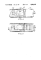
- FIG. 5 is a bottom view of the embodiment of FIG. 4.
- FIG. 6 is a longitudinal cross-sectional view of the embodiment of FIG. 4.
- FIG. 7 is a cross-sectional view of the second embodiment, taken along line 7--7 of FIG. 6.
- FIG. 8 is a partially broken-away cross-sectional view of the second embodiment, taken along line 8--8 of FIG. 6, showing the optical elements of the device.
- FIG. 9A is a block diagram of a computer work station employing the second embodiment of the OCR scanner/computer mouse device shown in FIGS. 4-8.
- FIG. 9B is a block diagram of a computer work station employing the first embodiment of the OCR scanner/computer mouse device shown in FIGS. 1-3.
- FIG. 10 is a diagrammatic view illustrative of the inter-relation of the computer system application program, its Basic Input Output System (BIOS) and the data received from the computer keyboard and the OCR scanner/computer mouse device.
- BIOS Basic Input Output System
- FIG. 11 is a simplified flow diagram of the operation of the BIOS employed in the systems of FIGS. 9A and 9B.
- FIG. 12 is a simplified operational flow diagram of the operation of the OCR scanner/computer mouse device with the system depicted in FIG. 9A.
- FIG. 13 is a simplied operational flow diagram of the operation of the OCR scanner/computer mouse device with the system depicted in FIG. 9B.
- the device 20 takes the form of a housing 25 constructed for hand-held use by the system user.
- the housing 25 contains the optical elements and transducer utilized to capture images of the character data being scanned by the device.
- the device 20 is positioned in the partially brokenaway diagrammatic perspective view of FIG. 1 for operation in an optical character recognition mode over a page 15 bearing several lines 16 of characters.
- the housing 25 contains an opto-electronic transducer 27 for optically and electronically capturing images of characters in a tangible medium, such as text which is printed, typed or handwritten on paper such as page 15.
- the transducer 27 may comprise, for example, a 64 ⁇ 256 pixel photosensitive array for capturing successive optical image frames or frame segments.
- An exemplary commercial device suitable for use as the photosensitive array is the IS32A product marketed by Micron Technology, Inc., Boise, Idaho. This device is functionally a 64K dynamic random access memory, packaged to allow an image to be focused directly on the silicon die.
- Alternative transducers are available, such as CCD sensors.
- the camera further comprises an internal light source for illuminating the surface of the medium bearing the characters.
- the light source comprises two light emitting diodes (LEDs) 29A and 29B, arranged to direct the generated light via respective lens elements 29E and 29D onto the surface of the page 15 bearing the lines 16 of characters, such that light reflected therefrom is directed by lens 29F onto the transducer array 27.
- lens elements 29D-E are plano-convex lens.
- the light source further comprises a driver circuit (not shown) capable of turning the LED devices on and off at a rapid repetition rate.
- the illumination source is in the form of a stroboscopic light source illuminating the medium surface.
- the stroboscopic light source in operation, as the device 20 is moved by hand along a line of characters, for example, a line of text printed on paper, light generated by the light source is projected onto the medium surface, and reflected therefrom onto the opto-electronic array, the intensity of the reflected light being spatially modulated in accordance with the particular character or characters being scanned.
- the opto-electronic array transforms the optical character data in the reflected light into digital data, with each pixel having a binary "1" or "0" associated therewith, with one value representing white and the other value representing black.
- the digital image data may be read out of the array as a sequence of digital video data.
- the video data represents a sequence of image frames or frame segments, each comprising a video image data packet and an associated packet of device "housekeeping" or status data.
- the system 20 further comprises a video processor 30 which receives the digital video data representing each image or frame from the opto-electronic transducer 27.
- the video processor 30 is more fully described in pending application Ser. No. 048,100, entitled “Adaptive Image Acquisition System,” filed on May 8, 1987, and assigned to the assignee of this application. The entire contents of this co-pending application is incorporated herein by this reference.
- the video processor 30 controls the camera exposure control function and performs correlation functions on the successive frames of the video data to provide a sequence of edited video data frames or frame segments, in the form of a data packet for each frame or frame segment, wherein duplicative character data have been removed from the edited frames.
- the result is video data representing a sequence of frames or frame segments, analogous to a "filmstrip," which capture the character sequence, but which do not contain duplicative character data.
- the video processor 30 is embodied in one or more integrated circuits contained within the housing of the hand-held device 20, although it may be located at an external location.
- the output of the processor 30 comprises a digital bit stream of packets of video image data and associated device status data packets.
- the device 20 (FIG. 1) further comprises a plurality of camera function keys 26A-26E which are positioned to allow tactile operation by the user.
- These keys may comprise, for example, normally open spring-biased pushbutton switches. The status of the keys is monitored, and the event of key closure or release results in issuance of a particular key token signal corresponding to the particular key.
- the edited video data from the video processor 30 and device function key status signals representing the status of the function keys 26A-26E are respectively coupled via a multi-wire electrical cable 31 to the particular utilization device, typically a computer system.
- FIG. 2 a block diagram of the main electrical elements of device 20 of FIG. 1 is shown.
- the video processor 30 is shown in the form of an integrated circuit located within the housing of the device 20.
- the device 20 comprises the opto-electronic transducer array 27 and a frame buffer memory 28, which are coupled to the video processor 30 by address bus 32.
- a control bus 33 between the video processor and the frame buffer 28 provides the control lines needed for the processor 30 to control the frame buffer 28.
- Serial video data is transferred from array 27 to processor 30 over line 37.
- the cooperation of the array 27 and frame buffer 28 permits the video processor 30 to perform a correlation process between successive image data frames to eliminate duplicative character information.
- the frame buffer is employed to store the three most current frames of image data. By comparing two successive data frames resulting from scanning of the camera along a line of character text, for example, the image data which is overlapped between the two frames, i.e., duplicated, or frame segment may be identified so that an edited image frame may be constructed which contains only new image data, i.e., data not captured in the previous data frame.
- the edited frame data is then transmitted via cable 31 for further processing as described below.
- the video processor 30 also controls the camera light source, which comprises in this embodiment two light emitting diodes (LEDs) 29A and 29B.
- the video processor controls the application of DC power to the LEDs 29A and 29B by gating transistor 29C on and off.
- the processor 30 may control the duty cycle and repetition rate at which the LEDs are operated. Each cycle comprises a programmable "soak" time period during which the LEDs are turned on to illuminate the medium, a "read” period during which the pixels of the array 27 are read, a refresh time period during which unused array pixels are refreshed, and a programmable wait time period.
- the light source illuminates the medium only during the "soak” interval; since the transducer array is not illuminated with reflected light during the array "read” time period, blurring of the resultant image is reduced.
- the "soak” time period i.e., the time period during each cycle that the array 27 is exposed to the scanned image, is adjusted as a function of the reflective characteristics of the medium.
- Power is transferred to the elements of the device 20 (FIG. 1) via cable 31, and device data signals are transferred via cable 31 to the computer system or terminal.
- the electrical umbilical cable 31 may be replaced with a wireless infrared link, wherein the digital information to be exchanged between the device 20 and the computer system is modulated on an infrared carrier, and the information is subsequently decoded.
- the device 20 receives its electrical power from a self-contained battery pack.
- the device 20 further comprises a pair of tracking wheels 24 (FIG. 1) mounted for rotation about axis 32. In the position shown in FIG. 1, these tracking wheels engage the surface of sheet 15, and serve to assist the user in tracking the device 20 along a line 16 of text.
- the device 20 is shown in position relative to page 15 to perform a computer mouse X-Y movement transducing function.
- a floating ball 21 mounted in a socket in the side of the housing 25 facing the surface 15 frictionally engages the surface 15, and is rotated as the user slides the device 20 over the work surface to position the computer terminal cursor as desired.
- Frictionally coupled to the ball 21 are a pair of transducers 21a, 21b mounted orthogonally to detect rotation of the ball about two orthogonal axes representing the coordinate X and Y axes (shown in FIG. 3 relative to the housing 25).
- the ball and transducers serve to translate the compound movement of the device 20 over the surface of the page 15 into compound X and Y cursor position signals for the computer.
- the particular orientations of the X and Y axis are a matter of choice.
- the device 20 includes a first plurality of OCR mode function control switches 26A-26C, located on surface 25A of housing 25 readily accessible to the user when the device 20 is positioned for OCR use as shown in FIG. 1, and a second plurality of position mode function control switches 26D-26E, positioned on surface 25B of housing 25, readily accessible to the user when the device 20 is positioned for computer mouse, cursor control use as shown in FIG. 3.
- These first and second pluralities of control switches enable the user to conveniently activate the desired mode of operation of the device 20, i.e., either the OCR scanner mode or the computer mouse cursor control mode.
- FIGS. 4-8 a second embodiment of an optical scanner/computer mouse device is disclosed.
- This device 120 is adapted for use in both the OCR mode and computer mouse modes while disposed in the same position relative to the medium bearing the characters or the work surface.
- the X-Y transducer comprises the opto-electronic imaging array. It is known to employ signal correlation processing of successive images or "bit maps" of a work surface to provide an output indicative of the direction and amount of movement of the cursor control device relative to an optical contrasting input to the array; U.S. Pat. No. 4,521,772 discloses such a computer mouse device. U.S. Pat. No.
- 4,546,347 discloses another computer mouse device employing an optical position transducer instead of a mechanical position transducer arrangement.
- the disclosures of U.S. Pat. Nos. 4,521,772 and 4,546,347 are incorporated herein by reference.
- the invention may alternatively be implemented using an optical X-Y movement transducer instead of a mechanical transducer.
- Separate signal processing is provided to process the image data provided from the imaging array and to generate the X-Y movement information.
- the function controls on the device select the device operating mode, and hence the signal processing to be performed on the image data, i.e., OCR processing or X-Y position processing.
- Device 120 comprises a housing 125, with a plurality of user-actuated switches 126A-C disposed along an upper surface thereof (FIG. 4).
- a section 125A of the housing 125 is fabricated of a transparent material to enable the user to view the area of the page bearing the lines of characters during OCR use.
- FIGS. 7 and 8 illustrate the primary optical elements of the device 120.
- the light source of this embodiment comprises a pair of LEDs (only LED 129A is visible in the partially broken-away cross-sectional view of FIG. 8) and converging lens elements 129D and 129E.
- the LEDs and lens elements are arranged to direct the generated light onto folding mirror 129F for reflection onto the surface 150 over which the device 120 is being scanned.
- the reflected light from surface 150 is in turn reflected by mirror 129F through lens 127a onto the imaging array 127.
- the electrical umbilical cable 131 is connected to printed wiring board 140, which serves to distribute electrical power and data signals between cable 131, function controls 126A-C, LEDs 129A, 129B, and imaging array 127.
- the function controls 126A-C preferably comprise spring-biased switches which in the closed position depress a metal spring contact into contact with a printed wire contact point on board 140.
- switch 126B is disclosed in FIG. 6, and comprises metal spring contact 126B' having one end which may be urged into contact with board 140 by function control stud 126B".
- One of the function controls 126A-C may be employed to provide a mode selection signal for selecting the OCR mode, and another of the function controls employed to provide a mode selection signal for selecting the computer mouse mode.
- FIGS. 9A and 9B Computer terminal systems respectively employing the two disclosed embodiments of the invention are shown in the general block diagrams of FIGS. 9A and 9B, the system of FIG. 9A employing the OCR scanner/computer mouse device described with respect to FIGS. 4-8, and the system of FIG. 9B employing the device described with respect to FIGS. 1-3.
- the hand-held scanner/mouse device 120 is connected via its umbilical cord 131 to a controller module 200.
- the scanner device 120 provides composite video information comprising successive frames of image data captured by the image transducer and associated scanner/mouse device "housekeeping" or status data, such as the status of the respective camera function keys to module 200.
- the controller module comprises a data separator 210, a function key processor 220, an OCR processor 230, and X-Y position processor 240.
- the data separator receives the composite video data from the scanner 120 and separates the image data and the function key status data, sending the image data to the OCR processor 230 and to the X-Y position processor 240, and the function key status data to the function key data processor 220.
- the processor 220 Based on the status of one or more of the function keys, e.g., whether the OCR or X-Y movement (mouse) function is selected, the processor 220 enables the operation of either the OCR processor 230 or the X-Y position processor 240.
- the processor 230 When in the OCR mode, the processor 230 operates on the image data to provide data indicative of recognized characters on line 201.
- the processor 240 When in the computer mouse mode of operation, the processor 240 operates on the data from separator 210 to provide data indicative of scanner movements in the X and Y directions on line 202.
- the processor 240 performs the optical position correlation functions described with respect to the system shown and described in U.S. Pat. No. 4,521,772.
- Computer work station 250 includes a CRT and CPU, with respective input ports 251, 252 for the character data on line 201 and the X, Y movement data on line 202. Another input port 253 receives status data on line 203 from the function key processor 220.
- a keyboard 255 is connected to a keyboard port 254 of the computer station 250.
- the computer 250 and keyboard 255 may comprise a personal computer system, such as an IBM PC/XT personal computer for example.
- the controller module 200 is preferably embodied in a controller circuit card received in a circuit card expansion connector of the IBM PC/XT.
- the IBM PC/XT model personal computer is an "open architecture" computer, wherein a peripheral card device may be plugged into a circuit card expansion connector, and have access to the computer data and address bus.
- a peripheral card device may be plugged into a circuit card expansion connector, and have access to the computer data and address bus.
- Each circuit card connector has all the bus signals available to it, and the peripheral card device can be configured to define a unique port address or a redundant port address. Most address space defined by the system can be used by any peripheral device.
- the keyboard input port 253 is uniquely defined by the manufacturer, and the ports 251, 252 and 254 are defined to accept data in accordance with the same protocol as the keyboard 255 data.
- the character data received from the OCR processor 230 will be processed by computer system 250 as if the characters were produced by an operator and keyboard 255. Thus, a look-up function is performed by the OCR processor 230 to provide a keyboard code corresponding to the identified character.
- the ⁇ X, ⁇ Y movement information received at port 251 will be processed in a manner similar to the keyboard data in that the ⁇ X, ⁇ Y information will be translated into a series of left/right and up/down arrow keyboard commands.
- the function key processor 220 receives data indicative of the status of the various device function keys, and is adapted to perform a look-up function when a particular key is activated by the user to provide a corresponding code at a keyboard port 253 of the computer system 250.
- the code is user-selected to emulate a predetermined keyboard character, symbol or function key.
- the system shown in FIG. 9B employs the OCR camera/mouse device 20 of FIGS. 1-3, and is similar to that of FIG. 9A, except that X-Y movement data from the mechanical transducer is directed to the X-Y position processor 240' directly, without passing through the data separator 210'.
- the scanner/mouse function keys directly enable either the OCR processor 230' or X-Y position processor 240', so that the appropriate input data is provided to the computer terminal 250.
- the device 20 is shown diagrammatically in FIG. 9B, with ball 21 and X and Y movement transducers 21A and 21B, respectively.
- BIOS Basic Input Output System
- BIOS Basic Input Output System
- the BIOS directs input data from the keyboard (manually entered data such as alphabetic, symbols, numeric data, cursor control, and function codes), and directs the data to the particular application program.
- FIG. 12 is a simplified block diagram illustrative of the operations provided by the BIOS program when employed with the system shown in FIGS. 8A and 8B.
- the BIOS program receives a call from the application program for data input.
- a decision is made as to whether any keyboard data has been entered. If so, then at step 310, the keyboard port is read and, at step 315 the data is saved, and returned to the calling application program, and the program operation is returned at point 320 to the application program.
- a second decision point 325 is entered to determine whether there is any data received from the scanner/mouse device 120. If not, BIOS program operation branches to return point 320 to return to the application program. If scanner/mouse data is present, then at step 330, the scanner ports 251 and 252 are read, and at step 315, the data is saved and then returned to the calling application program.
- step 400 scanner operation is initialized.
- decision point 405 the system determines whether the device operator has selected the OCR or "mouse" position or mode. If the mouse mode has been selected, then at step 410, the system determines whether any mouse function keys are active. If so, at step 415 a decision is made to determine whether the same key had been active in the last program cycle, and if so, operation branches to step 420. If the key had not been active in the last cycle, then a look-up function is performed at step 425 to find the code(s) associated with the active key, the codes are output at step 440, and program operation returns to step 405.
- step 420 a decision is made to determine if there is any detected optical sensor activity. If not, the program operation returns to step 405. If optical activity is detected at step 420, the optical data is converted to ⁇ X, ⁇ Y data at step 430. At step 435, a look-up function is employed to determine the cursor codes associated with the ⁇ X, ⁇ Y data. At step 440, the codes are output and scanner operation return to step 405.
- OCR mode is selected by the operator (step 405). Any active OCR function keys are examined and their respective code(s) outputted (steps 445, 47, 475 and 440). If any optical activity is detected (step 430), then the image data is acquired (step 455), an optical character recognition function is performed on the image data (step 460), the character codes associated with the recognized characters are looked up (step 465) and the codes output at step 440.
- FIG. 13 is a flow diagram of the operation of the scanner/mouse device 20 (FIGS. 1-3) employed in the system shown in FIG. 9B.
- the various steps set forth in FIG. 13 are identical to those in FIG. 13, except that in step 420', a determination is made as to whether any motion activity is detected from the mechanical transducer 21, 21A, 21B, and at step 430', the detected motion activity is converted to ⁇ X, ⁇ Y.
Abstract
Description
Claims (6)
Priority Applications (1)
| Application Number | Priority Date | Filing Date | Title |
|---|---|---|---|
| US07/055,162 US4804949A (en) | 1987-03-20 | 1987-05-27 | Hand-held optical scanner and computer mouse |
Applications Claiming Priority (2)
| Application Number | Priority Date | Filing Date | Title |
|---|---|---|---|
| US2831187A | 1987-03-20 | 1987-03-20 | |
| US07/055,162 US4804949A (en) | 1987-03-20 | 1987-05-27 | Hand-held optical scanner and computer mouse |
Related Parent Applications (1)
| Application Number | Title | Priority Date | Filing Date |
|---|---|---|---|
| US2831187A Continuation-In-Part | 1987-03-20 | 1987-03-20 |
Publications (1)
| Publication Number | Publication Date |
|---|---|
| US4804949A true US4804949A (en) | 1989-02-14 |
Family
ID=26703538
Family Applications (1)
| Application Number | Title | Priority Date | Filing Date |
|---|---|---|---|
| US07/055,162 Expired - Lifetime US4804949A (en) | 1987-03-20 | 1987-05-27 | Hand-held optical scanner and computer mouse |
Country Status (1)
| Country | Link |
|---|---|
| US (1) | US4804949A (en) |
Cited By (126)
| Publication number | Priority date | Publication date | Assignee | Title |
|---|---|---|---|---|
| US4906843A (en) * | 1987-12-31 | 1990-03-06 | Marq Technolgies | Combination mouse, optical scanner and digitizer puck |
| WO1990005963A1 (en) * | 1988-11-15 | 1990-05-31 | Msc Technologies, Inc. | Method for mapping scanned pixel data |
| US4939508A (en) * | 1988-10-31 | 1990-07-03 | Emtek Health Care Systems, Inc. | Point and select device |
| US4978305A (en) * | 1989-06-06 | 1990-12-18 | Educational Testing Service | Free response test grading method |
| US5034598A (en) * | 1989-12-29 | 1991-07-23 | Hewlett-Packard Company | Keyboard emulation system providing audible feedback without a built-in transducer |
| EP0453587A1 (en) * | 1990-04-23 | 1991-10-30 | San-Yih Cheng | Computer mouse |
| GB2244623A (en) * | 1990-03-05 | 1991-12-04 | Bmc Micro Ind Limited | Multi-directional hand scanner and mouse |
| US5115227A (en) * | 1987-06-22 | 1992-05-19 | Sharp Kabushiki Kaisha | Input device possessing plural functions |
| US5126955A (en) * | 1989-02-10 | 1992-06-30 | Kabushiki Kaisha Toshiba | Manually sweepable apparatus housed in a computer main body |
| US5132673A (en) * | 1990-03-06 | 1992-07-21 | Digi-Rule Inc. | Hand held digitizer |
| EP0551778A1 (en) * | 1992-01-17 | 1993-07-21 | Sextant Avionique | Cursor multimode control device for a display tube unit |
| US5291009A (en) * | 1992-02-27 | 1994-03-01 | Roustaei Alexander R | Optical scanning head |
| US5291028A (en) * | 1991-07-25 | 1994-03-01 | International Business Machines Corporation | Optical device for sensing marks on a surface using green light impinging at least sixty-five degrees to the normal |
| US5307424A (en) * | 1990-12-12 | 1994-04-26 | Eberhard Kuehl | Character recognition system |
| US5311208A (en) * | 1991-10-03 | 1994-05-10 | Xerox Corporation | Mouse that prints |
| US5354977A (en) * | 1992-02-27 | 1994-10-11 | Alex Roustaei | Optical scanning head |
| US5448050A (en) * | 1992-11-13 | 1995-09-05 | Psc Inc. | Integrated bar code reading and location mouse |
| WO1996021922A1 (en) * | 1995-01-11 | 1996-07-18 | Ziarno Witold A | Display cursor controlling device for reading card information |
| US5550362A (en) * | 1992-11-20 | 1996-08-27 | Intermec Corporation | Method and apparatus for calibrating a bar code scanner |
| DE19519124A1 (en) * | 1995-05-17 | 1996-11-21 | Victor Victorovic Vetckanov | Manually-operated optical input device e.g. mouse, for computer inputs |
| US5596753A (en) * | 1994-11-10 | 1997-01-21 | Fairhaven Software, Inc. | Scanner interactive application program |
| US5633489A (en) * | 1992-06-03 | 1997-05-27 | Symbol Technologies, Inc. | Combination mouse and scanner for reading optically encoded indicia |
| EP0782321A3 (en) * | 1995-12-27 | 1997-10-15 | At & T Corp | Combination mouse and area imager |
| US5756981A (en) * | 1992-02-27 | 1998-05-26 | Symbol Technologies, Inc. | Optical scanner for reading and decoding one- and-two-dimensional symbologies at variable depths of field including memory efficient high speed image processing means and high accuracy image analysis means |
| US5786582A (en) * | 1992-02-27 | 1998-07-28 | Symbol Technologies, Inc. | Optical scanner for reading and decoding one- and two-dimensional symbologies at variable depths of field |
| US5812777A (en) * | 1995-12-28 | 1998-09-22 | Compaq Computer Corporation | Remote terminal operation |
| US5887086A (en) * | 1994-04-15 | 1999-03-23 | Canon Kabushiki Kaisha | Image pick-up apparatus |
| DE19744441A1 (en) * | 1997-10-08 | 1999-04-15 | Sick Ag | Computer mouse with opto electronic sensing |
| US5898418A (en) * | 1995-03-06 | 1999-04-27 | Kao; Pin-Chi | Magnetically operated display |
| US5909521A (en) * | 1996-02-14 | 1999-06-01 | Nec Corporation | Multi-shot still image reader |
| US5912659A (en) * | 1997-09-03 | 1999-06-15 | International Business Machines Corporation | Graphics display pointer with integrated selection |
| GB2336195A (en) * | 1998-04-09 | 1999-10-13 | Thomas Norman Reid | Computer mouse |
| WO1999060468A1 (en) * | 1998-04-30 | 1999-11-25 | C Technologies Ab | Input unit, method for using the same and input system |
| WO2000008593A2 (en) * | 1998-08-07 | 2000-02-17 | Thomas Teufel | Combined mouse |
| WO2000038103A2 (en) * | 1998-12-21 | 2000-06-29 | Microsoft Corporation | Image sensing operator input device |
| WO2000042595A1 (en) * | 1999-01-19 | 2000-07-20 | Sequel Imaging, Inc. | Light and color sensing pointing device |
| US6119939A (en) * | 1998-07-08 | 2000-09-19 | Welch Allyn, Inc. | Optical assembly for barcode scanner |
| US6164544A (en) * | 1998-07-08 | 2000-12-26 | Welch Allyn Data Collection, Inc. | Adjustable illumination system for a barcode scanner |
| US6172354B1 (en) | 1998-01-28 | 2001-01-09 | Microsoft Corporation | Operator input device |
| EP1081606A2 (en) * | 1999-08-31 | 2001-03-07 | comMouse AG | Method and mouse with display for navigation in a computer network |
| WO2001061455A1 (en) * | 2000-02-18 | 2001-08-23 | Anoto Ab | Input unit arrangement |
| DE10009018A1 (en) * | 2000-02-25 | 2001-08-30 | Birgit Ruppert | Scanner mouse for taking a reading of a surface travelled over by the mouse acts as an electronic ADP input device connected to a scanner with a reading head for the scanner integrated in it. |
| US6305608B1 (en) * | 1998-06-04 | 2001-10-23 | Olympus Optical Co., Ltd. | Pen type code reader |
| US20010035861A1 (en) * | 2000-02-18 | 2001-11-01 | Petter Ericson | Controlling and electronic device |
| US6347163B2 (en) | 1994-10-26 | 2002-02-12 | Symbol Technologies, Inc. | System for reading two-dimensional images using ambient and/or projected light |
| US20020044134A1 (en) * | 2000-02-18 | 2002-04-18 | Petter Ericson | Input unit arrangement |
| US6385352B1 (en) | 1994-10-26 | 2002-05-07 | Symbol Technologies, Inc. | System and method for reading and comparing two-dimensional images |
| EP1107171A3 (en) * | 1999-12-06 | 2002-11-27 | Xerox Corporation | Method and apparatus for implementing a camera mouse |
| US6501460B1 (en) * | 2001-09-05 | 2002-12-31 | Samsung Electro-Mechanics Co., Ltd. | Light-receiving unit for optical mouse and optical mouse having the same |
| US6513717B2 (en) * | 2000-12-07 | 2003-02-04 | Digimarc Corporation | Integrated cursor control and scanner device |
| US6531692B1 (en) | 1999-03-22 | 2003-03-11 | Microsoft Corporation | Optical coupling assembly for image sensing operator input device |
| WO2003091868A1 (en) * | 2002-04-25 | 2003-11-06 | Young-Chan Moon | Apparatus and method for implementing mouse function and scanner function alternatively |
| US20040001046A1 (en) * | 2002-07-01 | 2004-01-01 | Chen Shu-Fen | Optical mouse |
| US6727887B1 (en) * | 1995-01-05 | 2004-04-27 | International Business Machines Corporation | Wireless pointing device for remote cursor control |
| US20040165793A1 (en) * | 1989-09-29 | 2004-08-26 | Intermec Ip Corp. | Apparatus and method for collection of handwritten data |
| US6783069B1 (en) | 1999-12-06 | 2004-08-31 | Xerox Corporation | Method and apparatus for implementing a camera mouse |
| US6788293B1 (en) * | 1999-12-01 | 2004-09-07 | Silverbrook Research Pty Ltd | Viewer with code sensor |
| US20040208369A1 (en) * | 2003-04-18 | 2004-10-21 | Mitsuo Nakayama | Image processing terminal apparatus, system and method |
| US20040208346A1 (en) * | 2003-04-18 | 2004-10-21 | Izhak Baharav | System and method for multiplexing illumination in combined finger recognition and finger navigation module |
| US20040208347A1 (en) * | 2003-04-18 | 2004-10-21 | Izhak Baharav | System and method for time-space multiplexing in finger-imaging applications |
| US20040208348A1 (en) * | 2003-04-18 | 2004-10-21 | Izhak Baharav | Imaging system and apparatus for combining finger recognition and finger navigation |
| US6844871B1 (en) | 1999-11-05 | 2005-01-18 | Microsoft Corporation | Method and apparatus for computer input using six degrees of freedom |
| US20050011954A1 (en) * | 1998-07-08 | 2005-01-20 | Hennick Robert J. | Image sensor assembly for optical reader |
| US20050057510A1 (en) * | 2003-09-16 | 2005-03-17 | Baines Donald A. | Scanning optical mouse |
| US20050078088A1 (en) * | 1999-05-19 | 2005-04-14 | Davis Bruce L. | Enhanced input peripheral |
| US6906699B1 (en) * | 1998-04-30 | 2005-06-14 | C Technologies Ab | Input unit, method for using the same and input system |
| US20050146501A1 (en) * | 2003-11-28 | 2005-07-07 | Cliff Chen | Wireless mouse with a PC camera |
| US20050160294A1 (en) * | 2001-12-18 | 2005-07-21 | Labrec Brian C. | Multiple image security features for identification documents and methods of making same |
| US6950094B2 (en) | 1998-03-30 | 2005-09-27 | Agilent Technologies, Inc | Seeing eye mouse for a computer system |
| US6965873B1 (en) | 1998-04-16 | 2005-11-15 | Digimarc Corporation | Electronic commerce using optical input device |
| US20060026078A1 (en) * | 2004-02-15 | 2006-02-02 | King Martin T | Capturing text from rendered documents using supplemental information |
| US20060041605A1 (en) * | 2004-04-01 | 2006-02-23 | King Martin T | Determining actions involving captured information and electronic content associated with rendered documents |
| US20060041484A1 (en) * | 2004-04-01 | 2006-02-23 | King Martin T | Methods and systems for initiating application processes by data capture from rendered documents |
| US20060053097A1 (en) * | 2004-04-01 | 2006-03-09 | King Martin T | Searching and accessing documents on private networks for use with captures from rendered documents |
| US20060081714A1 (en) * | 2004-08-23 | 2006-04-20 | King Martin T | Portable scanning device |
| US20060098899A1 (en) * | 2004-04-01 | 2006-05-11 | King Martin T | Handheld device for capturing text from both a document printed on paper and a document displayed on a dynamic display device |
| US20060098900A1 (en) * | 2004-09-27 | 2006-05-11 | King Martin T | Secure data gathering from rendered documents |
| US20060122983A1 (en) * | 2004-12-03 | 2006-06-08 | King Martin T | Locating electronic instances of documents based on rendered instances, document fragment digest generation, and digest based document fragment determination |
| US20060136629A1 (en) * | 2004-08-18 | 2006-06-22 | King Martin T | Scanner having connected and unconnected operational behaviors |
| US20060256371A1 (en) * | 2004-12-03 | 2006-11-16 | King Martin T | Association of a portable scanner with input/output and storage devices |
| US20070140770A1 (en) * | 2005-12-20 | 2007-06-21 | Writt John T | User interface for a hand-operated printer |
| US20070139507A1 (en) * | 2005-12-20 | 2007-06-21 | Ahne Adam J | Hand-operated printer having a user interface |
| US20080137971A1 (en) * | 2004-04-01 | 2008-06-12 | Exbiblio B.V. | Method and System For Character Recognition |
| US20080180412A1 (en) * | 2007-01-31 | 2008-07-31 | Microsoft Corporation | Dual mode digitizer |
| US20090225207A1 (en) * | 2002-12-23 | 2009-09-10 | Atlab Inc. | Optical pointing device and method of adjusting exposure time and comparison voltage range of the optical pointing device |
| US20100219239A1 (en) * | 1999-05-25 | 2010-09-02 | Silverbrook Research Pty Ltd | Method of interacting with printed substrate |
| US7824029B2 (en) | 2002-05-10 | 2010-11-02 | L-1 Secure Credentialing, Inc. | Identification card printer-assembler for over the counter card issuing |
| US20100278453A1 (en) * | 2006-09-15 | 2010-11-04 | King Martin T | Capture and display of annotations in paper and electronic documents |
| US20100296131A1 (en) * | 2009-05-20 | 2010-11-25 | Dacuda Ag | Real-time display of images acquired by a handheld scanner |
| US20100296140A1 (en) * | 2009-05-20 | 2010-11-25 | Dacuda Ag | Handheld scanner with high image quality |
| US20100296129A1 (en) * | 2009-05-20 | 2010-11-25 | Dacuda Ag | Automatic sizing of images acquired by a handheld scanner |
| US20110022940A1 (en) * | 2004-12-03 | 2011-01-27 | King Martin T | Processing techniques for visual capture data from a rendered document |
| US20110025842A1 (en) * | 2009-02-18 | 2011-02-03 | King Martin T | Automatically capturing information, such as capturing information using a document-aware device |
| US20110033080A1 (en) * | 2004-05-17 | 2011-02-10 | Exbiblio B.V. | Processing techniques for text capture from a rendered document |
| US20110043652A1 (en) * | 2009-03-12 | 2011-02-24 | King Martin T | Automatically providing content associated with captured information, such as information captured in real-time |
| US20110078585A1 (en) * | 2004-07-19 | 2011-03-31 | King Martin T | Automatic modification of web pages |
| US20110145068A1 (en) * | 2007-09-17 | 2011-06-16 | King Martin T | Associating rendered advertisements with digital content |
| US20110142371A1 (en) * | 2006-09-08 | 2011-06-16 | King Martin T | Optical scanners, such as hand-held optical scanners |
| US20110153653A1 (en) * | 2009-12-09 | 2011-06-23 | Exbiblio B.V. | Image search using text-based elements within the contents of images |
| US20110167075A1 (en) * | 2009-12-04 | 2011-07-07 | King Martin T | Using gestalt information to identify locations in printed information |
| US20110234815A1 (en) * | 2010-03-25 | 2011-09-29 | Dacuda Ag | Synchronization of navigation and image information for handheld scanner |
| US20110234497A1 (en) * | 2010-03-25 | 2011-09-29 | Dacuda Ag | Computer peripheral for scanning |
| US20120327484A1 (en) * | 2011-06-22 | 2012-12-27 | Lg Electronics Inc. | Scanning technology |
| US20130048836A1 (en) * | 2010-04-05 | 2013-02-28 | Alphamicron Incorporated | Electronically switchable optical device with a multi-functional optical control apparatus and methods for operating the same |
| US8441696B2 (en) | 2009-05-20 | 2013-05-14 | Dacuda Ag | Continuous scanning with a handheld scanner |
| US8442331B2 (en) | 2004-02-15 | 2013-05-14 | Google Inc. | Capturing text from rendered documents using supplemental information |
| US8447066B2 (en) | 2009-03-12 | 2013-05-21 | Google Inc. | Performing actions based on capturing information from rendered documents, such as documents under copyright |
| US8505090B2 (en) | 2004-04-01 | 2013-08-06 | Google Inc. | Archive of text captures from rendered documents |
| US8620083B2 (en) | 2004-12-03 | 2013-12-31 | Google Inc. | Method and system for character recognition |
| US8633894B1 (en) | 2008-10-15 | 2014-01-21 | Marvell International Ltd. | Folded focal length optics for an optical movement sensor |
| US8781228B2 (en) | 2004-04-01 | 2014-07-15 | Google Inc. | Triggering actions in response to optically or acoustically capturing keywords from a rendered document |
| US8892495B2 (en) | 1991-12-23 | 2014-11-18 | Blanding Hovenweep, Llc | Adaptive pattern recognition based controller apparatus and method and human-interface therefore |
| US9116890B2 (en) | 2004-04-01 | 2015-08-25 | Google Inc. | Triggering actions in response to optically or acoustically capturing keywords from a rendered document |
| US9143638B2 (en) | 2004-04-01 | 2015-09-22 | Google Inc. | Data capture from rendered documents using handheld device |
| US9268852B2 (en) | 2004-02-15 | 2016-02-23 | Google Inc. | Search engines and systems with handheld document data capture devices |
| US9535563B2 (en) | 1999-02-01 | 2017-01-03 | Blanding Hovenweep, Llc | Internet appliance system and method |
| US20170307707A1 (en) * | 2014-10-13 | 2017-10-26 | Koninklijke Philips N.V. | Mutli-shot magnetic resonance imaging system and method |
| US10095052B2 (en) | 2010-04-05 | 2018-10-09 | Alphamicron Incorporated | Electronically switchable optical device with a multi-functional optical control apparatus and methods for operating the same |
| US10142522B2 (en) | 2013-12-03 | 2018-11-27 | Ml Netherlands C.V. | User feedback for real-time checking and improving quality of scanned image |
| US10298898B2 (en) | 2013-08-31 | 2019-05-21 | Ml Netherlands C.V. | User feedback for real-time checking and improving quality of scanned image |
| US10410321B2 (en) | 2014-01-07 | 2019-09-10 | MN Netherlands C.V. | Dynamic updating of a composite image |
| US10484561B2 (en) | 2014-05-12 | 2019-11-19 | Ml Netherlands C.V. | Method and apparatus for scanning and printing a 3D object |
| US10708491B2 (en) | 2014-01-07 | 2020-07-07 | Ml Netherlands C.V. | Adaptive camera control for reducing motion blur during real-time image capture |
| US10706626B1 (en) * | 2015-12-09 | 2020-07-07 | Roger Brent | Augmented reality procedural system |
| US11132590B2 (en) | 2019-12-12 | 2021-09-28 | Lablightar Inc. | Augmented camera for improved spatial localization and spatial orientation determination |
| US11386303B2 (en) | 2018-01-04 | 2022-07-12 | LabLightAR, Inc. | Procedural language and content generation environment for use in augmented reality/mixed reality systems to support laboratory and related operations |
Citations (10)
| Publication number | Priority date | Publication date | Assignee | Title |
|---|---|---|---|---|
| US4180799A (en) * | 1978-04-21 | 1979-12-25 | Caere Corporation | Apparatus and method for recognizing characters |
| EP0016400A2 (en) * | 1979-03-20 | 1980-10-01 | Agfa-Gevaert AG | Information processing device for entering and further processing of optical information recorded on an information carrier |
| US4364035A (en) * | 1981-05-18 | 1982-12-14 | Kirsch Steven T | Electro-optical mouse |
| WO1983001853A1 (en) * | 1981-11-17 | 1983-05-26 | Ncr Co | Image capturing apparatus |
| US4464652A (en) * | 1982-07-19 | 1984-08-07 | Apple Computer, Inc. | Cursor control device for use with display systems |
| JPS6019284A (en) * | 1983-07-13 | 1985-01-31 | Nippon Denki Kaigai Shijiyou Kaihatsu Kk | Manual figure and character reading device |
| US4521772A (en) * | 1981-08-28 | 1985-06-04 | Xerox Corporation | Cursor control device |
| US4581761A (en) * | 1984-05-22 | 1986-04-08 | Nec Corporation | Manual image scanning system |
| US4631400A (en) * | 1984-01-20 | 1986-12-23 | California Institute Of Technology | Correlating optical motion detector |
| US4686329A (en) * | 1985-06-21 | 1987-08-11 | Advanced Robotic Technology, Inc. | Absolute position mouse |
-
1987
- 1987-05-27 US US07/055,162 patent/US4804949A/en not_active Expired - Lifetime
Patent Citations (10)
| Publication number | Priority date | Publication date | Assignee | Title |
|---|---|---|---|---|
| US4180799A (en) * | 1978-04-21 | 1979-12-25 | Caere Corporation | Apparatus and method for recognizing characters |
| EP0016400A2 (en) * | 1979-03-20 | 1980-10-01 | Agfa-Gevaert AG | Information processing device for entering and further processing of optical information recorded on an information carrier |
| US4364035A (en) * | 1981-05-18 | 1982-12-14 | Kirsch Steven T | Electro-optical mouse |
| US4521772A (en) * | 1981-08-28 | 1985-06-04 | Xerox Corporation | Cursor control device |
| WO1983001853A1 (en) * | 1981-11-17 | 1983-05-26 | Ncr Co | Image capturing apparatus |
| US4464652A (en) * | 1982-07-19 | 1984-08-07 | Apple Computer, Inc. | Cursor control device for use with display systems |
| JPS6019284A (en) * | 1983-07-13 | 1985-01-31 | Nippon Denki Kaigai Shijiyou Kaihatsu Kk | Manual figure and character reading device |
| US4631400A (en) * | 1984-01-20 | 1986-12-23 | California Institute Of Technology | Correlating optical motion detector |
| US4581761A (en) * | 1984-05-22 | 1986-04-08 | Nec Corporation | Manual image scanning system |
| US4686329A (en) * | 1985-06-21 | 1987-08-11 | Advanced Robotic Technology, Inc. | Absolute position mouse |
Non-Patent Citations (2)
| Title |
|---|
| Namba et al; "Toshiba OCR Hand Scanner, RH-520"; Toshiba Review, No. 113; Jan-Feb. 1978; pp. 23-25. |
| Namba et al; Toshiba OCR Hand Scanner, RH 520 ; Toshiba Review, No. 113; Jan Feb. 1978; pp. 23 25. * |
Cited By (272)
| Publication number | Priority date | Publication date | Assignee | Title |
|---|---|---|---|---|
| US7646941B2 (en) * | 1986-08-15 | 2010-01-12 | Broadcom Corporation | Data capture apparatus with handwritten data receiving component |
| US20070065046A1 (en) * | 1986-08-15 | 2007-03-22 | Hacker David C | Data capture apparatus with handwritten data receiving component |
| US5115227A (en) * | 1987-06-22 | 1992-05-19 | Sharp Kabushiki Kaisha | Input device possessing plural functions |
| US4906843A (en) * | 1987-12-31 | 1990-03-06 | Marq Technolgies | Combination mouse, optical scanner and digitizer puck |
| US4939508A (en) * | 1988-10-31 | 1990-07-03 | Emtek Health Care Systems, Inc. | Point and select device |
| US4942621A (en) * | 1988-11-15 | 1990-07-17 | Msc Technologies, Inc. | Method for mapping scanned pixel data |
| AU625289B2 (en) * | 1988-11-15 | 1992-07-09 | Msc Technologies, Inc. | Method for mapping scanned pixel data |
| WO1990005963A1 (en) * | 1988-11-15 | 1990-05-31 | Msc Technologies, Inc. | Method for mapping scanned pixel data |
| US5126955A (en) * | 1989-02-10 | 1992-06-30 | Kabushiki Kaisha Toshiba | Manually sweepable apparatus housed in a computer main body |
| US4978305A (en) * | 1989-06-06 | 1990-12-18 | Educational Testing Service | Free response test grading method |
| US20040165793A1 (en) * | 1989-09-29 | 2004-08-26 | Intermec Ip Corp. | Apparatus and method for collection of handwritten data |
| US7336853B2 (en) * | 1989-09-29 | 2008-02-26 | Intermec Ip Corp. | Apparatus and method for collection of handwritten data |
| EP0441032A2 (en) * | 1989-12-29 | 1991-08-14 | Hewlett-Packard Company | Keyboard emulation system |
| US5034598A (en) * | 1989-12-29 | 1991-07-23 | Hewlett-Packard Company | Keyboard emulation system providing audible feedback without a built-in transducer |
| EP0441032A3 (en) * | 1989-12-29 | 1993-03-31 | Hewlett-Packard Company | Keyboard emulation system |
| GB2244623A (en) * | 1990-03-05 | 1991-12-04 | Bmc Micro Ind Limited | Multi-directional hand scanner and mouse |
| US5355146A (en) * | 1990-03-05 | 1994-10-11 | Bmc Micro-Industries Ltd. | Multi-directional hand scanner and mouse |
| US5132673A (en) * | 1990-03-06 | 1992-07-21 | Digi-Rule Inc. | Hand held digitizer |
| US5157381A (en) * | 1990-04-23 | 1992-10-20 | Cheng San Yih | Computer mouse |
| EP0453587A1 (en) * | 1990-04-23 | 1991-10-30 | San-Yih Cheng | Computer mouse |
| US5307424A (en) * | 1990-12-12 | 1994-04-26 | Eberhard Kuehl | Character recognition system |
| US5291028A (en) * | 1991-07-25 | 1994-03-01 | International Business Machines Corporation | Optical device for sensing marks on a surface using green light impinging at least sixty-five degrees to the normal |
| US5311208A (en) * | 1991-10-03 | 1994-05-10 | Xerox Corporation | Mouse that prints |
| US8892495B2 (en) | 1991-12-23 | 2014-11-18 | Blanding Hovenweep, Llc | Adaptive pattern recognition based controller apparatus and method and human-interface therefore |
| EP0551778A1 (en) * | 1992-01-17 | 1993-07-21 | Sextant Avionique | Cursor multimode control device for a display tube unit |
| FR2686440A1 (en) * | 1992-01-17 | 1993-07-23 | Sextant Avionique | DEVICE FOR MULTIMODE MANAGEMENT OF A CURSOR ON THE SCREEN OF A DISPLAY DEVICE. |
| US6034672A (en) * | 1992-01-17 | 2000-03-07 | Sextant Avionique | Device for multimode management of a cursor on the screen of a display device |
| US5354977A (en) * | 1992-02-27 | 1994-10-11 | Alex Roustaei | Optical scanning head |
| USRE36528E (en) * | 1992-02-27 | 2000-01-25 | Symbol Technologies, Inc. | Optical scanning head |
| US5786582A (en) * | 1992-02-27 | 1998-07-28 | Symbol Technologies, Inc. | Optical scanner for reading and decoding one- and two-dimensional symbologies at variable depths of field |
| US5291009A (en) * | 1992-02-27 | 1994-03-01 | Roustaei Alexander R | Optical scanning head |
| US5756981A (en) * | 1992-02-27 | 1998-05-26 | Symbol Technologies, Inc. | Optical scanner for reading and decoding one- and-two-dimensional symbologies at variable depths of field including memory efficient high speed image processing means and high accuracy image analysis means |
| US5633489A (en) * | 1992-06-03 | 1997-05-27 | Symbol Technologies, Inc. | Combination mouse and scanner for reading optically encoded indicia |
| US5814804A (en) * | 1992-11-13 | 1998-09-29 | Psc Inc. | Optical scanner activated with position locator |
| US5448050A (en) * | 1992-11-13 | 1995-09-05 | Psc Inc. | Integrated bar code reading and location mouse |
| US5550362A (en) * | 1992-11-20 | 1996-08-27 | Intermec Corporation | Method and apparatus for calibrating a bar code scanner |
| US5887086A (en) * | 1994-04-15 | 1999-03-23 | Canon Kabushiki Kaisha | Image pick-up apparatus |
| US6347163B2 (en) | 1994-10-26 | 2002-02-12 | Symbol Technologies, Inc. | System for reading two-dimensional images using ambient and/or projected light |
| US6385352B1 (en) | 1994-10-26 | 2002-05-07 | Symbol Technologies, Inc. | System and method for reading and comparing two-dimensional images |
| US5596753A (en) * | 1994-11-10 | 1997-01-21 | Fairhaven Software, Inc. | Scanner interactive application program |
| US6727887B1 (en) * | 1995-01-05 | 2004-04-27 | International Business Machines Corporation | Wireless pointing device for remote cursor control |
| WO1996021922A1 (en) * | 1995-01-11 | 1996-07-18 | Ziarno Witold A | Display cursor controlling device for reading card information |
| US5550561A (en) * | 1995-01-11 | 1996-08-27 | Ziarno; Witold A. | Display cursor controlling device for reading card information from an information bearing credit or debit card |
| US6025825A (en) * | 1995-03-06 | 2000-02-15 | Lite Vision Corporation Of Taiwan | Magnetically operated display |
| US5898418A (en) * | 1995-03-06 | 1999-04-27 | Kao; Pin-Chi | Magnetically operated display |
| DE19519124A1 (en) * | 1995-05-17 | 1996-11-21 | Victor Victorovic Vetckanov | Manually-operated optical input device e.g. mouse, for computer inputs |
| US7800585B2 (en) | 1995-10-06 | 2010-09-21 | Avago Technologies Ecbu Ip (Singapore) Pte. Ltd. | Method of operating an optical mouse |
| US7791590B1 (en) | 1995-10-06 | 2010-09-07 | Avago Technologies Ecbu Ip (Singapore) Pte. Ltd. | Optical mouse with uniform level detection |
| US20080055243A1 (en) * | 1995-10-06 | 2008-03-06 | Gordon Gary B | Method of operating an optical mouse |
| US20080048983A1 (en) * | 1995-10-06 | 2008-02-28 | Gordon Gary B | Method of operating an optical mouse |
| US7808485B2 (en) | 1995-10-06 | 2010-10-05 | Avago Technologies Ecbu Ip (Singapore) Pte. Ltd. | Method of operating an optical mouse |
| US7907120B2 (en) | 1995-10-06 | 2011-03-15 | Avago Technologies Ecbu Ip (Singapore) Pte. Ltd. | Optical mouse with uniform level detection method |
| US8350812B2 (en) | 1995-10-06 | 2013-01-08 | Pixart Imaging Inc. | Method and arrangement for tracking movement relative to a surface |
| US20110141022A1 (en) * | 1995-10-06 | 2011-06-16 | Avago Technologies Ecbu Ip (Singapore) Pte. Ltd. | Method and arrangement for tracking movement relative to a surface |
| US20050231484A1 (en) * | 1995-10-06 | 2005-10-20 | Agilent Technologies, Inc. | Optical mouse with uniform level detection method |
| US20070103439A1 (en) * | 1995-10-06 | 2007-05-10 | Avago Technologies, Ltd. | Method of operating an optical mouse |
| US8212778B2 (en) | 1995-10-06 | 2012-07-03 | Avago Technologies Ecbu Ip (Singapore) Pte. Ltd. | Imaging and navigation arrangement for controlling a cursor |
| US5909209A (en) * | 1995-12-27 | 1999-06-01 | Lucent Technologies, Inc. | Combination mouse and area imager |
| EP0782321A3 (en) * | 1995-12-27 | 1997-10-15 | At & T Corp | Combination mouse and area imager |
| US5838905A (en) * | 1995-12-28 | 1998-11-17 | Compaq Computer Corp. | Remote terminal operation |
| US5812777A (en) * | 1995-12-28 | 1998-09-22 | Compaq Computer Corporation | Remote terminal operation |
| US5909521A (en) * | 1996-02-14 | 1999-06-01 | Nec Corporation | Multi-shot still image reader |
| US5912659A (en) * | 1997-09-03 | 1999-06-15 | International Business Machines Corporation | Graphics display pointer with integrated selection |
| DE19744441A1 (en) * | 1997-10-08 | 1999-04-15 | Sick Ag | Computer mouse with opto electronic sensing |
| US6172354B1 (en) | 1998-01-28 | 2001-01-09 | Microsoft Corporation | Operator input device |
| US6950094B2 (en) | 1998-03-30 | 2005-09-27 | Agilent Technologies, Inc | Seeing eye mouse for a computer system |
| GB2336195B (en) * | 1998-04-09 | 2001-06-06 | Thomas Norman Reid | Computer mouse |
| GB2336195A (en) * | 1998-04-09 | 1999-10-13 | Thomas Norman Reid | Computer mouse |
| US6965873B1 (en) | 1998-04-16 | 2005-11-15 | Digimarc Corporation | Electronic commerce using optical input device |
| WO1999060468A1 (en) * | 1998-04-30 | 1999-11-25 | C Technologies Ab | Input unit, method for using the same and input system |
| US6906699B1 (en) * | 1998-04-30 | 2005-06-14 | C Technologies Ab | Input unit, method for using the same and input system |
| AU758036B2 (en) * | 1998-04-30 | 2003-03-13 | C Technologies Ab | Input unit, method for using the same and input system |
| US6305608B1 (en) * | 1998-06-04 | 2001-10-23 | Olympus Optical Co., Ltd. | Pen type code reader |
| US6119939A (en) * | 1998-07-08 | 2000-09-19 | Welch Allyn, Inc. | Optical assembly for barcode scanner |
| US6164544A (en) * | 1998-07-08 | 2000-12-26 | Welch Allyn Data Collection, Inc. | Adjustable illumination system for a barcode scanner |
| US8096472B2 (en) | 1998-07-08 | 2012-01-17 | Hand Held Products, Inc. | Image sensor assembly for optical reader |
| US20050011954A1 (en) * | 1998-07-08 | 2005-01-20 | Hennick Robert J. | Image sensor assembly for optical reader |
| US7306155B2 (en) | 1998-07-08 | 2007-12-11 | Hand Held Products, Inc. | Image sensor assembly for optical reader |
| US20080128511A1 (en) * | 1998-07-08 | 2008-06-05 | Schwartz Eric D | Image sensor assembly for optical reader |
| WO2000008593A3 (en) * | 1998-08-07 | 2000-05-25 | Thomas Teufel | Combined mouse |
| WO2000008593A2 (en) * | 1998-08-07 | 2000-02-17 | Thomas Teufel | Combined mouse |
| WO2000038103A3 (en) * | 1998-12-21 | 2000-10-26 | Microsoft Corp | Image sensing operator input device |
| US6373047B1 (en) | 1998-12-21 | 2002-04-16 | Microsoft Corp | Image sensing operator input device |
| EP1291810A2 (en) * | 1998-12-21 | 2003-03-12 | Microsoft Corporation | Image sensing operator input device |
| US6303924B1 (en) | 1998-12-21 | 2001-10-16 | Microsoft Corporation | Image sensing operator input device |
| WO2000038103A2 (en) * | 1998-12-21 | 2000-06-29 | Microsoft Corporation | Image sensing operator input device |
| KR100771064B1 (en) | 1998-12-21 | 2007-10-30 | 마이크로소프트 코포레이션 | Image sensing operator input device |
| KR100767655B1 (en) * | 1998-12-21 | 2007-10-17 | 마이크로소프트 코포레이션 | Image sensing operator input device |
| EP1291810A3 (en) * | 1998-12-21 | 2006-02-01 | Microsoft Corporation | Image sensing operator input device |
| WO2000042595A1 (en) * | 1999-01-19 | 2000-07-20 | Sequel Imaging, Inc. | Light and color sensing pointing device |
| US9535563B2 (en) | 1999-02-01 | 2017-01-03 | Blanding Hovenweep, Llc | Internet appliance system and method |
| US6531692B1 (en) | 1999-03-22 | 2003-03-11 | Microsoft Corporation | Optical coupling assembly for image sensing operator input device |
| US7164413B2 (en) | 1999-05-19 | 2007-01-16 | Digimarc Corporation | Enhanced input peripheral |
| US20050078088A1 (en) * | 1999-05-19 | 2005-04-14 | Davis Bruce L. | Enhanced input peripheral |
| US20070109266A1 (en) * | 1999-05-19 | 2007-05-17 | Davis Bruce L | Enhanced Input Peripheral |
| US20100219239A1 (en) * | 1999-05-25 | 2010-09-02 | Silverbrook Research Pty Ltd | Method of interacting with printed substrate |
| EP1081606A3 (en) * | 1999-08-31 | 2001-05-02 | comMouse AG | Method and mouse with display for navigation in a computer network |
| EP1081606A2 (en) * | 1999-08-31 | 2001-03-07 | comMouse AG | Method and mouse with display for navigation in a computer network |
| US7245287B2 (en) | 1999-11-05 | 2007-07-17 | Microsoft Corporation | Method and apparatus for computer input using six degrees of freedom |
| US7554528B2 (en) | 1999-11-05 | 2009-06-30 | Microsoft Corporation | Method and apparatus for computer input using six degrees of freedom |
| US6844871B1 (en) | 1999-11-05 | 2005-01-18 | Microsoft Corporation | Method and apparatus for computer input using six degrees of freedom |
| US7355587B2 (en) | 1999-11-05 | 2008-04-08 | Microsoft Corporation | Method and apparatus for computer input using six degrees of freedom |
| US20050057530A1 (en) * | 1999-11-05 | 2005-03-17 | Microsoft Corporation | Method and apparatus for computer input using six degrees of freedom |
| US20050062719A1 (en) * | 1999-11-05 | 2005-03-24 | Microsoft Corporation | Method and apparatus for computer input using six degrees of freedom |
| US20050062718A1 (en) * | 1999-11-05 | 2005-03-24 | Microsoft Corporation | Method and apparatus for computer input using six degrees of freedom |
| US8063882B2 (en) | 1999-11-05 | 2011-11-22 | Microsoft Corporation | Generating audio signals based on input device position |
| US20050093824A1 (en) * | 1999-11-05 | 2005-05-05 | Microsoft Corporation | Method and apparatus for computer input using six degrees of freedom |
| US20050093823A1 (en) * | 1999-11-05 | 2005-05-05 | Microsoft Corporation | Method and apparatus for computer input using six degrees of freedom |
| US7460106B2 (en) | 1999-11-05 | 2008-12-02 | Microsoft Corporation | Method and apparatus for computer input using six degrees of freedom |
| US7518596B2 (en) | 1999-11-05 | 2009-04-14 | Microsoft Corporation | Method and apparatus for computer input using six degrees of freedom |
| US20090160771A1 (en) * | 1999-11-05 | 2009-06-25 | Microsoft Corporation | Generating audio signals based on input device position |
| US6788293B1 (en) * | 1999-12-01 | 2004-09-07 | Silverbrook Research Pty Ltd | Viewer with code sensor |
| US20080237348A1 (en) * | 1999-12-01 | 2008-10-02 | Silverbrook Research Pty Ltd | Viewing Device For Use With Coded Data On A Surface |
| US20050035315A1 (en) * | 1999-12-01 | 2005-02-17 | Paul Lapstun | Viewer configured to display, and method of displaying, information on a display to at least partially take into account a position of the viewer relative to a surface |
| US7388221B2 (en) | 1999-12-01 | 2008-06-17 | Silverbrook Research Pty Ltd | Viewer and method for displaying information based on viewer position |
| US20050145807A1 (en) * | 1999-12-01 | 2005-07-07 | Paul Lapstun | Device for interacting with an interface surface |
| US7148499B2 (en) | 1999-12-01 | 2006-12-12 | Silverbrook Research Pty Ltd | Device for interacting with an interface surface |
| US7671334B2 (en) | 1999-12-01 | 2010-03-02 | Silverbrook Research Pty Ltd | Viewing device for use with coded data on a surface |
| US7019319B2 (en) | 1999-12-01 | 2006-03-28 | Silverbrook Research Pty Ltd | Viewer configured to display, and method of displaying, information on a display to at least partially take into account a position of the viewer relative to a surface |
| US6783069B1 (en) | 1999-12-06 | 2004-08-31 | Xerox Corporation | Method and apparatus for implementing a camera mouse |
| EP1107171A3 (en) * | 1999-12-06 | 2002-11-27 | Xerox Corporation | Method and apparatus for implementing a camera mouse |
| WO2001061454A1 (en) * | 2000-02-18 | 2001-08-23 | Anoto Ab | Controlling an electronic device |
| US7345673B2 (en) * | 2000-02-18 | 2008-03-18 | Anoto Ab | Input unit arrangement |
| US20060007183A1 (en) * | 2000-02-18 | 2006-01-12 | Petter Ericson | Input unit arrangement |
| WO2001061455A1 (en) * | 2000-02-18 | 2001-08-23 | Anoto Ab | Input unit arrangement |
| US6992655B2 (en) | 2000-02-18 | 2006-01-31 | Anoto Ab | Input unit arrangement |
| US20010035861A1 (en) * | 2000-02-18 | 2001-11-01 | Petter Ericson | Controlling and electronic device |
| US20020044134A1 (en) * | 2000-02-18 | 2002-04-18 | Petter Ericson | Input unit arrangement |
| US7054487B2 (en) * | 2000-02-18 | 2006-05-30 | Anoto Ip Lic Handelsbolag | Controlling and electronic device |
| DE10009018A1 (en) * | 2000-02-25 | 2001-08-30 | Birgit Ruppert | Scanner mouse for taking a reading of a surface travelled over by the mouse acts as an electronic ADP input device connected to a scanner with a reading head for the scanner integrated in it. |
| US6513717B2 (en) * | 2000-12-07 | 2003-02-04 | Digimarc Corporation | Integrated cursor control and scanner device |
| US6501460B1 (en) * | 2001-09-05 | 2002-12-31 | Samsung Electro-Mechanics Co., Ltd. | Light-receiving unit for optical mouse and optical mouse having the same |
| US8025239B2 (en) | 2001-12-18 | 2011-09-27 | L-1 Secure Credentialing, Inc. | Multiple image security features for identification documents and methods of making same |
| US7744001B2 (en) | 2001-12-18 | 2010-06-29 | L-1 Secure Credentialing, Inc. | Multiple image security features for identification documents and methods of making same |
| US20050160294A1 (en) * | 2001-12-18 | 2005-07-21 | Labrec Brian C. | Multiple image security features for identification documents and methods of making same |
| KR100555587B1 (en) * | 2002-04-25 | 2006-03-03 | 문영찬 | Apparatus and method for implementing mouse function and scanner function alternatively |
| WO2003091868A1 (en) * | 2002-04-25 | 2003-11-06 | Young-Chan Moon | Apparatus and method for implementing mouse function and scanner function alternatively |
| US7824029B2 (en) | 2002-05-10 | 2010-11-02 | L-1 Secure Credentialing, Inc. | Identification card printer-assembler for over the counter card issuing |
| US20040001046A1 (en) * | 2002-07-01 | 2004-01-01 | Chen Shu-Fen | Optical mouse |
| US20090225207A1 (en) * | 2002-12-23 | 2009-09-10 | Atlab Inc. | Optical pointing device and method of adjusting exposure time and comparison voltage range of the optical pointing device |
| US20040208369A1 (en) * | 2003-04-18 | 2004-10-21 | Mitsuo Nakayama | Image processing terminal apparatus, system and method |
| US7164782B2 (en) | 2003-04-18 | 2007-01-16 | Avago Technologies Ecbu Ip (Singapore) Pte. Ltd. | System and method for time-space multiplexing in finger-imaging applications |
| US20040208346A1 (en) * | 2003-04-18 | 2004-10-21 | Izhak Baharav | System and method for multiplexing illumination in combined finger recognition and finger navigation module |
| US20040208348A1 (en) * | 2003-04-18 | 2004-10-21 | Izhak Baharav | Imaging system and apparatus for combining finger recognition and finger navigation |
| US20040208347A1 (en) * | 2003-04-18 | 2004-10-21 | Izhak Baharav | System and method for time-space multiplexing in finger-imaging applications |
| US7274808B2 (en) | 2003-04-18 | 2007-09-25 | Avago Technologies Ecbu Ip (Singapore)Pte Ltd | Imaging system and apparatus for combining finger recognition and finger navigation |
| US7158659B2 (en) | 2003-04-18 | 2007-01-02 | Avago Technologies Ecbu Ip (Singapore) Pte. Ltd. | System and method for multiplexing illumination in combined finger recognition and finger navigation module |
| US7477783B2 (en) * | 2003-04-18 | 2009-01-13 | Mitsuo Nakayama | Image processing terminal apparatus, system and method |
| US20050057510A1 (en) * | 2003-09-16 | 2005-03-17 | Baines Donald A. | Scanning optical mouse |
| US20050146501A1 (en) * | 2003-11-28 | 2005-07-07 | Cliff Chen | Wireless mouse with a PC camera |
| US7702624B2 (en) | 2004-02-15 | 2010-04-20 | Exbiblio, B.V. | Processing techniques for visual capture data from a rendered document |
| US8515816B2 (en) | 2004-02-15 | 2013-08-20 | Google Inc. | Aggregate analysis of text captures performed by multiple users from rendered documents |
| US7437023B2 (en) | 2004-02-15 | 2008-10-14 | Exbiblio B.V. | Methods, systems and computer program products for data gathering in a digital and hard copy document environment |
| US7421155B2 (en) | 2004-02-15 | 2008-09-02 | Exbiblio B.V. | Archive of text captures from rendered documents |
| US8831365B2 (en) | 2004-02-15 | 2014-09-09 | Google Inc. | Capturing text from rendered documents using supplement information |
| US8019648B2 (en) | 2004-02-15 | 2011-09-13 | Google Inc. | Search engines and systems with handheld document data capture devices |
| US8005720B2 (en) | 2004-02-15 | 2011-08-23 | Google Inc. | Applying scanned information to identify content |
| US9268852B2 (en) | 2004-02-15 | 2016-02-23 | Google Inc. | Search engines and systems with handheld document data capture devices |
| US20060026078A1 (en) * | 2004-02-15 | 2006-02-02 | King Martin T | Capturing text from rendered documents using supplemental information |
| US20060026140A1 (en) * | 2004-02-15 | 2006-02-02 | King Martin T | Content access with handheld document data capture devices |
| US7593605B2 (en) | 2004-02-15 | 2009-09-22 | Exbiblio B.V. | Data capture from rendered documents using handheld device |
| US7596269B2 (en) | 2004-02-15 | 2009-09-29 | Exbiblio B.V. | Triggering actions in response to optically or acoustically capturing keywords from a rendered document |
| US7599580B2 (en) | 2004-02-15 | 2009-10-06 | Exbiblio B.V. | Capturing text from rendered documents using supplemental information |
| US7599844B2 (en) | 2004-02-15 | 2009-10-06 | Exbiblio B.V. | Content access with handheld document data capture devices |
| US7606741B2 (en) | 2004-02-15 | 2009-10-20 | Exbibuo B.V. | Information gathering system and method |
| US20060023945A1 (en) * | 2004-02-15 | 2006-02-02 | King Martin T | Search engines and systems with handheld document data capture devices |
| US20060050996A1 (en) * | 2004-02-15 | 2006-03-09 | King Martin T | Archive of text captures from rendered documents |
| US20060029296A1 (en) * | 2004-02-15 | 2006-02-09 | King Martin T | Data capture from rendered documents using handheld device |
| US7707039B2 (en) | 2004-02-15 | 2010-04-27 | Exbiblio B.V. | Automatic modification of web pages |
| US7706611B2 (en) | 2004-02-15 | 2010-04-27 | Exbiblio B.V. | Method and system for character recognition |
| US7742953B2 (en) | 2004-02-15 | 2010-06-22 | Exbiblio B.V. | Adding information or functionality to a rendered document via association with an electronic counterpart |
| US20060036462A1 (en) * | 2004-02-15 | 2006-02-16 | King Martin T | Aggregate analysis of text captures performed by multiple users from rendered documents |
| US20060047639A1 (en) * | 2004-02-15 | 2006-03-02 | King Martin T | Adding information or functionality to a rendered document via association with an electronic counterpart |
| US20060041538A1 (en) * | 2004-02-15 | 2006-02-23 | King Martin T | Establishing an interactive environment for rendered documents |
| US8214387B2 (en) | 2004-02-15 | 2012-07-03 | Google Inc. | Document enhancement system and method |
| US20060041590A1 (en) * | 2004-02-15 | 2006-02-23 | King Martin T | Document enhancement system and method |
| US8442331B2 (en) | 2004-02-15 | 2013-05-14 | Google Inc. | Capturing text from rendered documents using supplemental information |
| US7818215B2 (en) | 2004-02-15 | 2010-10-19 | Exbiblio, B.V. | Processing techniques for text capture from a rendered document |
| US20060041828A1 (en) * | 2004-02-15 | 2006-02-23 | King Martin T | Triggering actions in response to optically or acoustically capturing keywords from a rendered document |
| US7831912B2 (en) | 2004-02-15 | 2010-11-09 | Exbiblio B. V. | Publishing techniques for adding value to a rendered document |
| US20060041484A1 (en) * | 2004-04-01 | 2006-02-23 | King Martin T | Methods and systems for initiating application processes by data capture from rendered documents |
| US8781228B2 (en) | 2004-04-01 | 2014-07-15 | Google Inc. | Triggering actions in response to optically or acoustically capturing keywords from a rendered document |
| US8505090B2 (en) | 2004-04-01 | 2013-08-06 | Google Inc. | Archive of text captures from rendered documents |
| US7812860B2 (en) | 2004-04-01 | 2010-10-12 | Exbiblio B.V. | Handheld device for capturing text from both a document printed on paper and a document displayed on a dynamic display device |
| US20060041605A1 (en) * | 2004-04-01 | 2006-02-23 | King Martin T | Determining actions involving captured information and electronic content associated with rendered documents |
| US9143638B2 (en) | 2004-04-01 | 2015-09-22 | Google Inc. | Data capture from rendered documents using handheld device |
| US9116890B2 (en) | 2004-04-01 | 2015-08-25 | Google Inc. | Triggering actions in response to optically or acoustically capturing keywords from a rendered document |
| US20060053097A1 (en) * | 2004-04-01 | 2006-03-09 | King Martin T | Searching and accessing documents on private networks for use with captures from rendered documents |
| US20060098899A1 (en) * | 2004-04-01 | 2006-05-11 | King Martin T | Handheld device for capturing text from both a document printed on paper and a document displayed on a dynamic display device |
| US9633013B2 (en) | 2004-04-01 | 2017-04-25 | Google Inc. | Triggering actions in response to optically or acoustically capturing keywords from a rendered document |
| US20080137971A1 (en) * | 2004-04-01 | 2008-06-12 | Exbiblio B.V. | Method and System For Character Recognition |
| US9514134B2 (en) | 2004-04-01 | 2016-12-06 | Google Inc. | Triggering actions in response to optically or acoustically capturing keywords from a rendered document |
| US8261094B2 (en) | 2004-04-19 | 2012-09-04 | Google Inc. | Secure data gathering from rendered documents |
| US9030699B2 (en) | 2004-04-19 | 2015-05-12 | Google Inc. | Association of a portable scanner with input/output and storage devices |
| US8799099B2 (en) | 2004-05-17 | 2014-08-05 | Google Inc. | Processing techniques for text capture from a rendered document |
| US8489624B2 (en) | 2004-05-17 | 2013-07-16 | Google, Inc. | Processing techniques for text capture from a rendered document |
| US20110033080A1 (en) * | 2004-05-17 | 2011-02-10 | Exbiblio B.V. | Processing techniques for text capture from a rendered document |
| US20110078585A1 (en) * | 2004-07-19 | 2011-03-31 | King Martin T | Automatic modification of web pages |
| US8346620B2 (en) | 2004-07-19 | 2013-01-01 | Google Inc. | Automatic modification of web pages |
| US9275051B2 (en) | 2004-07-19 | 2016-03-01 | Google Inc. | Automatic modification of web pages |
| US20060136629A1 (en) * | 2004-08-18 | 2006-06-22 | King Martin T | Scanner having connected and unconnected operational behaviors |
| US8179563B2 (en) | 2004-08-23 | 2012-05-15 | Google Inc. | Portable scanning device |
| US20060081714A1 (en) * | 2004-08-23 | 2006-04-20 | King Martin T | Portable scanning device |
| US20060098900A1 (en) * | 2004-09-27 | 2006-05-11 | King Martin T | Secure data gathering from rendered documents |
| US20060256371A1 (en) * | 2004-12-03 | 2006-11-16 | King Martin T | Association of a portable scanner with input/output and storage devices |
| US8953886B2 (en) | 2004-12-03 | 2015-02-10 | Google Inc. | Method and system for character recognition |
| US7990556B2 (en) | 2004-12-03 | 2011-08-02 | Google Inc. | Association of a portable scanner with input/output and storage devices |
| US8620083B2 (en) | 2004-12-03 | 2013-12-31 | Google Inc. | Method and system for character recognition |
| US20110022940A1 (en) * | 2004-12-03 | 2011-01-27 | King Martin T | Processing techniques for visual capture data from a rendered document |
| US8874504B2 (en) | 2004-12-03 | 2014-10-28 | Google Inc. | Processing techniques for visual capture data from a rendered document |
| US20060122983A1 (en) * | 2004-12-03 | 2006-06-08 | King Martin T | Locating electronic instances of documents based on rendered instances, document fragment digest generation, and digest based document fragment determination |
| US20070139507A1 (en) * | 2005-12-20 | 2007-06-21 | Ahne Adam J | Hand-operated printer having a user interface |
| US20070140770A1 (en) * | 2005-12-20 | 2007-06-21 | Writt John T | User interface for a hand-operated printer |
| US7524051B2 (en) | 2005-12-20 | 2009-04-28 | Lexmark International, Inc. | Hand-operated printer having a user interface |
| US7399129B2 (en) | 2005-12-20 | 2008-07-15 | Lexmark International, Inc. | User interface for a hand-operated printer |
| US20110142371A1 (en) * | 2006-09-08 | 2011-06-16 | King Martin T | Optical scanners, such as hand-held optical scanners |
| US8600196B2 (en) | 2006-09-08 | 2013-12-03 | Google Inc. | Optical scanners, such as hand-held optical scanners |
| US20100278453A1 (en) * | 2006-09-15 | 2010-11-04 | King Martin T | Capture and display of annotations in paper and electronic documents |
| US20080180412A1 (en) * | 2007-01-31 | 2008-07-31 | Microsoft Corporation | Dual mode digitizer |
| US20110145068A1 (en) * | 2007-09-17 | 2011-06-16 | King Martin T | Associating rendered advertisements with digital content |
| US9146626B1 (en) | 2008-10-15 | 2015-09-29 | Marvell International Ltd. | Optical movement sensor with light folding device |
| US8633894B1 (en) | 2008-10-15 | 2014-01-21 | Marvell International Ltd. | Folded focal length optics for an optical movement sensor |
| US8418055B2 (en) | 2009-02-18 | 2013-04-09 | Google Inc. | Identifying a document by performing spectral analysis on the contents of the document |
| US8638363B2 (en) | 2009-02-18 | 2014-01-28 | Google Inc. | Automatically capturing information, such as capturing information using a document-aware device |
| US20110025842A1 (en) * | 2009-02-18 | 2011-02-03 | King Martin T | Automatically capturing information, such as capturing information using a document-aware device |
| US20110043652A1 (en) * | 2009-03-12 | 2011-02-24 | King Martin T | Automatically providing content associated with captured information, such as information captured in real-time |
| US8990235B2 (en) | 2009-03-12 | 2015-03-24 | Google Inc. | Automatically providing content associated with captured information, such as information captured in real-time |
| US8447066B2 (en) | 2009-03-12 | 2013-05-21 | Google Inc. | Performing actions based on capturing information from rendered documents, such as documents under copyright |
| US9075779B2 (en) | 2009-03-12 | 2015-07-07 | Google Inc. | Performing actions based on capturing information from rendered documents, such as documents under copyright |
| US8441695B2 (en) | 2009-05-20 | 2013-05-14 | Dacuda Ag | Handheld scanner with high image quality |
| US20100296140A1 (en) * | 2009-05-20 | 2010-11-25 | Dacuda Ag | Handheld scanner with high image quality |
| US8582182B2 (en) | 2009-05-20 | 2013-11-12 | Dacuda Ag | Automatic sizing of images acquired by a handheld scanner |
| US20100296131A1 (en) * | 2009-05-20 | 2010-11-25 | Dacuda Ag | Real-time display of images acquired by a handheld scanner |
| US20100295868A1 (en) * | 2009-05-20 | 2010-11-25 | Dacuda Ag | Image processing for handheld scanner |
| US10225428B2 (en) | 2009-05-20 | 2019-03-05 | Ml Netherlands C.V. | Image processing for handheld scanner |
| US8723885B2 (en) | 2009-05-20 | 2014-05-13 | Dacuda Ag | Real-time display of images acquired by a handheld scanner |
| US9300834B2 (en) | 2009-05-20 | 2016-03-29 | Dacuda Ag | Image processing for handheld scanner |
| US8441696B2 (en) | 2009-05-20 | 2013-05-14 | Dacuda Ag | Continuous scanning with a handheld scanner |
| US20100296129A1 (en) * | 2009-05-20 | 2010-11-25 | Dacuda Ag | Automatic sizing of images acquired by a handheld scanner |
| US20110167075A1 (en) * | 2009-12-04 | 2011-07-07 | King Martin T | Using gestalt information to identify locations in printed information |
| US9081799B2 (en) | 2009-12-04 | 2015-07-14 | Google Inc. | Using gestalt information to identify locations in printed information |
| US20110153653A1 (en) * | 2009-12-09 | 2011-06-23 | Exbiblio B.V. | Image search using text-based elements within the contents of images |
| US9323784B2 (en) | 2009-12-09 | 2016-04-26 | Google Inc. | Image search using text-based elements within the contents of images |
| US20110234815A1 (en) * | 2010-03-25 | 2011-09-29 | Dacuda Ag | Synchronization of navigation and image information for handheld scanner |
| US20110234497A1 (en) * | 2010-03-25 | 2011-09-29 | Dacuda Ag | Computer peripheral for scanning |
| US8339467B2 (en) | 2010-03-25 | 2012-12-25 | Dacuda Ag | Synchronization of navigation and image information for handheld scanner |
| US8497840B2 (en) | 2010-03-25 | 2013-07-30 | Dacuda Ag | Computer peripheral for scanning |
| US9411174B2 (en) * | 2010-04-05 | 2016-08-09 | Alphamicron Incorporated | Electronically switchable optical device with a multi-functional optical control apparatus and methods for operating the same |
| US20130048836A1 (en) * | 2010-04-05 | 2013-02-28 | Alphamicron Incorporated | Electronically switchable optical device with a multi-functional optical control apparatus and methods for operating the same |
| US10095052B2 (en) | 2010-04-05 | 2018-10-09 | Alphamicron Incorporated | Electronically switchable optical device with a multi-functional optical control apparatus and methods for operating the same |
| US8988749B2 (en) * | 2011-06-22 | 2015-03-24 | Lg Electronics Inc. | Scanning technology |
| US20120327484A1 (en) * | 2011-06-22 | 2012-12-27 | Lg Electronics Inc. | Scanning technology |
| US10298898B2 (en) | 2013-08-31 | 2019-05-21 | Ml Netherlands C.V. | User feedback for real-time checking and improving quality of scanned image |
| US11563926B2 (en) | 2013-08-31 | 2023-01-24 | Magic Leap, Inc. | User feedback for real-time checking and improving quality of scanned image |
| US10841551B2 (en) | 2013-08-31 | 2020-11-17 | Ml Netherlands C.V. | User feedback for real-time checking and improving quality of scanned image |
| US11798130B2 (en) | 2013-12-03 | 2023-10-24 | Magic Leap, Inc. | User feedback for real-time checking and improving quality of scanned image |
| US10375279B2 (en) | 2013-12-03 | 2019-08-06 | Ml Netherlands C.V. | User feedback for real-time checking and improving quality of scanned image |
| US10142522B2 (en) | 2013-12-03 | 2018-11-27 | Ml Netherlands C.V. | User feedback for real-time checking and improving quality of scanned image |
| US10455128B2 (en) | 2013-12-03 | 2019-10-22 | Ml Netherlands C.V. | User feedback for real-time checking and improving quality of scanned image |
| US11115565B2 (en) | 2013-12-03 | 2021-09-07 | Ml Netherlands C.V. | User feedback for real-time checking and improving quality of scanned image |
| US10410321B2 (en) | 2014-01-07 | 2019-09-10 | MN Netherlands C.V. | Dynamic updating of a composite image |
| US10708491B2 (en) | 2014-01-07 | 2020-07-07 | Ml Netherlands C.V. | Adaptive camera control for reducing motion blur during real-time image capture |
| US11315217B2 (en) | 2014-01-07 | 2022-04-26 | Ml Netherlands C.V. | Dynamic updating of a composite image |
| US11516383B2 (en) | 2014-01-07 | 2022-11-29 | Magic Leap, Inc. | Adaptive camera control for reducing motion blur during real-time image capture |
| US10484561B2 (en) | 2014-05-12 | 2019-11-19 | Ml Netherlands C.V. | Method and apparatus for scanning and printing a 3D object |
| US11245806B2 (en) | 2014-05-12 | 2022-02-08 | Ml Netherlands C.V. | Method and apparatus for scanning and printing a 3D object |
| US20170307707A1 (en) * | 2014-10-13 | 2017-10-26 | Koninklijke Philips N.V. | Mutli-shot magnetic resonance imaging system and method |
| US11255938B2 (en) * | 2014-10-13 | 2022-02-22 | Koninklijke Philips N.V. | Mutli-shot magnetic resonance imaging system and method |
| US10706626B1 (en) * | 2015-12-09 | 2020-07-07 | Roger Brent | Augmented reality procedural system |
| US11386303B2 (en) | 2018-01-04 | 2022-07-12 | LabLightAR, Inc. | Procedural language and content generation environment for use in augmented reality/mixed reality systems to support laboratory and related operations |
| US11132590B2 (en) | 2019-12-12 | 2021-09-28 | Lablightar Inc. | Augmented camera for improved spatial localization and spatial orientation determination |
| US11727238B2 (en) | 2019-12-12 | 2023-08-15 | LabLightAR, Inc. | Augmented camera for improved spatial localization and spatial orientation determination |
Similar Documents
| Publication | Publication Date | Title |
|---|---|---|
| US4804949A (en) | Hand-held optical scanner and computer mouse | |
| US5814804A (en) | Optical scanner activated with position locator | |
| US6906699B1 (en) | Input unit, method for using the same and input system | |
| US5909209A (en) | Combination mouse and area imager | |
| AU758036B2 (en) | Input unit, method for using the same and input system | |
| US6335727B1 (en) | Information input device, position information holding device, and position recognizing system including them | |
| US20020117549A1 (en) | Barcode-readable computer mouse | |
| JPH11345079A (en) | Hand-held pointing device | |
| US5164585A (en) | Stylus/digitizer combination with elongate reflectors and linear CCD | |
| JPH11345074A (en) | Hand-held pointing and scanning device | |
| KR930013984A (en) | Pen computer | |
| GB2400715A (en) | Combined optical fingerprint recogniser and navigation control | |
| EP0957448A2 (en) | Optical code reader mouse | |
| US6538645B1 (en) | Computer input system utilizing a camera to sense point source | |
| WO1980002337A1 (en) | Input device for hand-written characters and patterns | |
| WO1981002083A1 (en) | Selective copying apparatus | |
| JP3387708B2 (en) | Input device such as computer and computer equipment using the same | |
| JP3523370B2 (en) | Data symbol reading device | |
| KR200215091Y1 (en) | Mouse device having a function of input characters | |
| CN1058823C (en) | Image processing system capable of eliminating automatically ripple figure in image | |
| CN101221475B (en) | Interactive control method of pen type data processing device | |
| JPH1078844A (en) | Information inputting device by camera and medium for recording program for the same | |
| MXPA00010541A (en) | Input unit, method for using the same and input system | |
| JPH0554152A (en) | Portable input/output device | |
| KR20060036779A (en) | A mouse which has code reader function |
Legal Events
| Date | Code | Title | Description |
|---|---|---|---|
| AS | Assignment |
Owner name: TRANSIMAGE CORPORATION, 910 BENICIA AVENUE, SUNNYV Free format text: ASSIGNMENT OF ASSIGNORS INTEREST.;ASSIGNOR:FAULKERSON, JAMES L.;REEL/FRAME:004792/0094 Effective date: 19870727 Owner name: TRANSIMAGE CORPORATION, 910 BENICIA AVENUE, SUNNYV Free format text: ASSIGNMENT OF ASSIGNORS INTEREST;ASSIGNOR:FAULKERSON, JAMES L.;REEL/FRAME:004792/0094 Effective date: 19870727 |
|
| AS | Assignment |
Owner name: EVEREX TI CORPORATION, A CA CORP. Free format text: ASSIGNMENT OF ASSIGNORS INTEREST.;ASSIGNOR:TRANSIMAGE CORPORATION;REEL/FRAME:004985/0330 Effective date: 19881007 |
|
| STCF | Information on status: patent grant |
Free format text: PATENTED CASE |
|
| AS | Assignment |
Owner name: CIT GROUP/CREDIT FINANCE, INC., THE, CALIFORNIA Free format text: SECURITY INTEREST;ASSIGNOR:EVEREX SYSTEMS, INC.;REEL/FRAME:005725/0015 Effective date: 19910604 |
|
| REFU | Refund |
Free format text: REFUND PROCESSED. MAINTENANCE FEE HAS ALREADY BEEN PAID (ORIGINAL EVENT CODE: R160); ENTITY STATUS OF PATENT OWNER: LARGE ENTITY |
|
| FEPP | Fee payment procedure |
Free format text: PAYOR NUMBER ASSIGNED (ORIGINAL EVENT CODE: ASPN); ENTITY STATUS OF PATENT OWNER: LARGE ENTITY |
|
| FPAY | Fee payment |
Year of fee payment: 4 |
|
| FEPP | Fee payment procedure |
Free format text: PAYER NUMBER DE-ASSIGNED (ORIGINAL EVENT CODE: RMPN); ENTITY STATUS OF PATENT OWNER: LARGE ENTITY |
|
| FPAY | Fee payment |
Year of fee payment: 8 |
|
| FPAY | Fee payment |
Year of fee payment: 12 |