US4796187A - Method for processing image data to select a target aimpoint - Google Patents
Method for processing image data to select a target aimpoint Download PDFInfo
- Publication number
- US4796187A US4796187A US06/946,233 US94623386A US4796187A US 4796187 A US4796187 A US 4796187A US 94623386 A US94623386 A US 94623386A US 4796187 A US4796187 A US 4796187A
- Authority
- US
- United States
- Prior art keywords
- target
- image
- scene
- center
- contiguous
- Prior art date
- Legal status (The legal status is an assumption and is not a legal conclusion. Google has not performed a legal analysis and makes no representation as to the accuracy of the status listed.)
- Expired - Lifetime
Links
Images


Classifications
-
- F—MECHANICAL ENGINEERING; LIGHTING; HEATING; WEAPONS; BLASTING
- F41—WEAPONS
- F41G—WEAPON SIGHTS; AIMING
- F41G7/00—Direction control systems for self-propelled missiles
- F41G7/20—Direction control systems for self-propelled missiles based on continuous observation of target position
- F41G7/22—Homing guidance systems
- F41G7/2273—Homing guidance systems characterised by the type of waves
- F41G7/2293—Homing guidance systems characterised by the type of waves using electromagnetic waves other than radio waves
-
- F—MECHANICAL ENGINEERING; LIGHTING; HEATING; WEAPONS; BLASTING
- F41—WEAPONS
- F41G—WEAPON SIGHTS; AIMING
- F41G7/00—Direction control systems for self-propelled missiles
- F41G7/20—Direction control systems for self-propelled missiles based on continuous observation of target position
- F41G7/22—Homing guidance systems
- F41G7/2226—Homing guidance systems comparing the observed data with stored target data, e.g. target configuration data
-
- F—MECHANICAL ENGINEERING; LIGHTING; HEATING; WEAPONS; BLASTING
- F41—WEAPONS
- F41G—WEAPON SIGHTS; AIMING
- F41G7/00—Direction control systems for self-propelled missiles
- F41G7/20—Direction control systems for self-propelled missiles based on continuous observation of target position
- F41G7/22—Homing guidance systems
- F41G7/2246—Active homing systems, i.e. comprising both a transmitter and a receiver
-
- F—MECHANICAL ENGINEERING; LIGHTING; HEATING; WEAPONS; BLASTING
- F41—WEAPONS
- F41G—WEAPON SIGHTS; AIMING
- F41G7/00—Direction control systems for self-propelled missiles
- F41G7/20—Direction control systems for self-propelled missiles based on continuous observation of target position
- F41G7/22—Homing guidance systems
- F41G7/2253—Passive homing systems, i.e. comprising a receiver and do not requiring an active illumination of the target
-
- F—MECHANICAL ENGINEERING; LIGHTING; HEATING; WEAPONS; BLASTING
- F41—WEAPONS
- F41G—WEAPON SIGHTS; AIMING
- F41G7/00—Direction control systems for self-propelled missiles
- F41G7/20—Direction control systems for self-propelled missiles based on continuous observation of target position
- F41G7/22—Homing guidance systems
- F41G7/2273—Homing guidance systems characterised by the type of waves
- F41G7/2286—Homing guidance systems characterised by the type of waves using radio waves
-
- G—PHYSICS
- G01—MEASURING; TESTING
- G01S—RADIO DIRECTION-FINDING; RADIO NAVIGATION; DETERMINING DISTANCE OR VELOCITY BY USE OF RADIO WAVES; LOCATING OR PRESENCE-DETECTING BY USE OF THE REFLECTION OR RERADIATION OF RADIO WAVES; ANALOGOUS ARRANGEMENTS USING OTHER WAVES
- G01S3/00—Direction-finders for determining the direction from which infrasonic, sonic, ultrasonic, or electromagnetic waves, or particle emission, not having a directional significance, are being received
- G01S3/78—Direction-finders for determining the direction from which infrasonic, sonic, ultrasonic, or electromagnetic waves, or particle emission, not having a directional significance, are being received using electromagnetic waves other than radio waves
- G01S3/782—Systems for determining direction or deviation from predetermined direction
- G01S3/785—Systems for determining direction or deviation from predetermined direction using adjustment of orientation of directivity characteristics of a detector or detector system to give a desired condition of signal derived from that detector or detector system
- G01S3/786—Systems for determining direction or deviation from predetermined direction using adjustment of orientation of directivity characteristics of a detector or detector system to give a desired condition of signal derived from that detector or detector system the desired condition being maintained automatically
- G01S3/7864—T.V. type tracking systems
-
- G—PHYSICS
- G06—COMPUTING; CALCULATING OR COUNTING
- G06T—IMAGE DATA PROCESSING OR GENERATION, IN GENERAL
- G06T7/00—Image analysis
- G06T7/60—Analysis of geometric attributes
- G06T7/62—Analysis of geometric attributes of area, perimeter, diameter or volume
-
- G—PHYSICS
- G06—COMPUTING; CALCULATING OR COUNTING
- G06T—IMAGE DATA PROCESSING OR GENERATION, IN GENERAL
- G06T7/00—Image analysis
- G06T7/60—Analysis of geometric attributes
- G06T7/66—Analysis of geometric attributes of image moments or centre of gravity
Definitions
- This invention relates to methods for processing data orginating from an imaging seeker device such as an imaging infrared device or a visual video device and possibly can be applied to other devices such as radar.
- the processed data is representative of the image content of a scene viewed by the seeker. More particularly, the invention relates to a method for distinguishing a selected target image from other images (clutter) in the scene and for selecting an aimpoint on the target of particular utility.
- Various imaging seeker/tracker systems are well known and used to guide missiles or other vehicles to their targets.
- One such system is referred to as a Gated Centroid Tracker. It is the function of such systems to process electrical signals representative of the image content of a scene viewed by the seeker and to select the target from among all other images in the scene and to select a specific aimpoint on the target.
- the primary method of distinguishing the target from non-target (i.e. "clutter") images is the mathematical formation of what is commonly referred to as a "gate" around the target. Any images located outside the gate are assumed to be clutter and are ignored when performing new aimpoint calculations. Such a technique is effective only if there is adequate separation between the target and the clutter. However, the performance of such a tracker may be degraded by the clutter if the clutter is close enough to the target to enter the gate. If clutter enters the gate, the gate may be "stolen” by the clutter resulting in an unacceptable aimpoint. Also, because the gated centroid tracker uses the mathematical centroid of the target as its aimpoint, the calculation of the aimpoint can be severely compromised by long target image slivers protruding from the main body of the target.
- the present invention comprises a seeker/tracker system for generating signals representative of the image content of a scene viewed by the system, together with means for processing such signals and controlling the aimpoint of the seeker so as to overcome the disadvantages discussed above.
- the method of the invention examines the various images in a viewed scene and selects those image segments which are contiguous and nearest to the center of the scene for further processing as the selected target.
- a unique probability function is thereby assigned which provides for a step increase in the probability of a segment being a target segment for those image segments which are contiguous and closest to the center of the scene (the presumed target aimpoint).
- a weighting function is used to determine how much influence a segment has on the calculation of a new aimpoint.
- the weighting function assigns the same weight to all such contiguous and central image segments and assigns zero weight to image segments which are not contiguous and centrally located.
- the image segments are processed to calculate a new aimpoint located at the mathematical median of the target image.
- Such a seeker tracker system can be referred to as a "contiguous median tracker", and is not susceptible to "gate stealing".
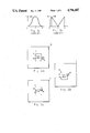
- FIGS. 1a and 1b depicts the probability distribution (1a) and the weighting function (1b) as used in processing pixel data in a Gated Centroid Tracker.
- FIGS. 2a, 2b, and 2c illustrate the phenomenon of "gate stealing".
- FIG. 3 illustrates a hypothetical scene viewed by a seeker/tracker to be subjected to analysis by the method of the invention.
- FIG. 4 illustrates the method of calculation of the contiguity tester.
- FIG. 5 illustrates the method of calculating the X-axis (horizontal) median position.
- FIG. 6 illustrates the method of calculating the Y-axis (vertical) median position.
- FIGS. 7a and 7b depict the resulting probability distribution and weighting function as used in processing pixel data to generate a new aimpoint.
- FIGS. 8, 9, and 10 show the location of the aimpoint if calculated using a middle, centroid and median calculation for targets of selected shapes.
- the centroid gated tracker is, under some conditions, susceptible to "gate stealing". This occurs when a large non-target image is close enough to the target image that an edge of the object just enters the gate. Even a small piece of the non-target object, at the edge of the gate, has a sizeable influence on the calculation of the location of the centroid (or aimpoint).
- the calculation of the aimpoint takes into account the presence of the non-target near the edge and calculates a new aimpoint which moves the gate toward the nontarget. Thus, during the next scene frame, more of the non-target is included in the gate and the situation compounds itself.
- FIG. 1a is a probability function that would be expected of typical tracker, illustrating the probability that an image located in the scene at position x is in fact part of the target.
- An image near the edge of the scene is expected to have a lower probability.
- FIG. 1b represents a weighting function as used in a typical centroid gated tracker.
- the weight that an image segment is assigned in calculating the new aimpoint varies depending on its position in the scene.
- weighting function is roughly the reciprocal of the probability function. In other words, if non-target segments enter the gate they have a stronger influence on the calculation of the new aimpoint than do the target segments. This contributes to the phenomenon known a "stealing the gate" as illustrated in FIGS. 2a, 2b and 2c.
- the "gate stealing" begins as shown in FIG. 2a.
- the seeker/tracker views a scene 10 which may include many potential targets and some clutter.
- the effect of these additional targets and clutter on the calculation of the aimpoint on the selected target 14 is theoretically held to a low level by mathematically generating a gate 12 around the target. All targets and objects outside the gate are rejected as clutter and are not further processed.
- a typical object of clutter such as clutter 18 may be located just outside the gate and may be of substantial size and sufficiently large to generate an image which will result in gate stealing should that clutter image enter the gate.
- FIG. 2b shows that due to target 14 movement or movement of clutter 18, an edge portion of clutter 18 has entered the gate 12. Because that edge portion of clutter 18 has entered the gate, it is further processed to calculate a new target aimpoint 16. The weight given to the edge portion is very high as shown by the weighting function of FIG. 1b. Thus, a new aimpoint is calculated as lying closer to clutter 18. The gate and aimpoint are thus shifted toward clutter 18 as shown in FIG. 2c. Thus target 14 appears to be to the left of center of gate 12. The aimpoint 16 has shifted toward clutter 18 and almost off of target 14. Gate 12 has shifted torward clutter 18 and hence a larger portion of clutter 18 now appears within the gate 12. This larger portion of clutter 18 now has a larger influence on the calculation of the succeeding aimpoint, and hence the "gate stealing" compounds itself.
- the method of the present invention processes the image data in a scene in a manner which eliminates "gate stealing" and also calculates a target aimpoint which is more efficient than is the calulation of the target centroid.
- the method of the invention is preferably implemented through software and specifically through a first algorithm referred to as the Continguity algorithm, and a second algorithm referred to as the Median algorithm.
- the function of the contiguity algorith is to find the single set of image segments that are contiguous and closest to the point where the target is believed to exist (i.e. the aimpoint of the previous image frame). Once such single set of image segments is located, all other image segments are rejected as clutter. Since the contiguity algorithm serves to reject all clutter, it should be evident that the algorithm can be used with or without a "gate". The algorithm will operate faster to locate the target if a "gate” is used since the gate would perform a "first cut” and eliminate the need for the algorithm to process many clearly clutter objects. However, the gate is not necessary. The algorithm can use the entire scene of the seeker for its processing and function to properly reject clutter.
- FIG. 3 shows objects 20-26 and target object 14. Also shown are a previous aimpoint 16 and a new aimpoint 16' calculated based on the information content of the scene.
- the algorithm which selects object 14 as the most probable target is best described with reference to the flow chart of the algorithm as shown in FIG. 4. Before getting into the details of FIG. 4, some preliminary operational information must be understood.
- the algorithm picks the contiguous image set which is closest to the aimpoint by keeping track of, and processing data representative of the gaps between image sets.
- each image segment on that line is compared to the previous image segment on that line. If the gap between the two segments is to the left of the gate center, then the old segment is rejected and the new segment is saved. If the gap is to the right of center, then processing is complete for that line since the segment closest to the center has already been found and saved. No subsequent segments can possibly be closer. As a result of this processing, only one segment per line is retained. While this may disregard target appendages, it will not throw-out the main body of the target.
- This method of processing the scene data is graphically illustrated by the flow chart of FIG. 4.
- the processing of data representative of images detected during the scan of a particular line in the image begins with the description contained in box 40.
- the number of image segments located on the line is determined and stored, as is the number of the line. For each image segment, a beginning and ending pixel location is stored.
- the data so stored is processed to determine which segment on the line is located closest to the centerline (aimpoint) of the image by the procedure indicated in boxes 50 through 60.
- Boxes 50a and 50b define a loop procedure. So long as there remain segments on a line which have not yet been analyzed (box 50a) the procedure in boxes 52 through 60 is followed.
- An option is to skip the rmaining segments when a segment to the right of the centerline is found. This may save some processing time. This option is shown is parentheses in FIG. 4. After each segment is analyzed the procedure increments to analyze the next segment (see box 50b).
- the locations of the center of the gaps between segments are determined and used to select the segment closest to the centerline.
- the first pixel in each line is always designated as the first STOP for that line.
- Pixel 1 is identified as the first STOP.
- Pixel 4 is identified as the START of segment one and pixel 6 is the STOP of segment one.
- the second segment has START at pixel 11 and STOP at pixel 13.
- the third segment is defined by START at 23 and STOP at 25.
- the first gap between segments is defined by the first STOP (which is pixel 1) and the new START of the next segment (which is pixel 4).
- Proceding to box 50b we increment to the next segment by analyzing the next gap.
- the next gap is defined by the STOP of the last stored segment (i.e. pixel 6) and the new START of the next segment on the line, which for line 4 is pixel 11.
- Box 52 finds the center of the new gap to be (11 plus 4) divided by 2 or 7.5. Since 7.5 is located to the left of center (pixel 13) the next segment, defined by pixels 11 through 13 must be located closer to the center than the previous segment (pixels 4-6).
- Box 52 calculates the center of the gap to be (23 plus 14) divided by 2, or 18.5. But 18.5 is greater than 13. Thus the center of this gap lies to the right of the center of the scene and the decision in Box 52 is thus false.
- Proceding through boxes 56 and 60 we either jump directly to the next line of pixels (if the line just completed was the first line of a new target image) or we now determine whether the segment just stored is contiguous to the segment previously stored. This can be done by comparing the pixel numbers of the stored segment on the current line with the pixel numbers of the stored segment on the previous line. If there are any common numbers the segments are determined to be contiguous. This criteria may vary. Overlap may be required or small gaps may be allowed. Small numbers of lines with no segments may also be allowed.
- the test for contiguity is made in box 70.
- the segment forms a part of a potentially new target.
- box 76 we branch through box 76 to box 78.
- box 78 we test to see whether the new non-contiguous segment is vertically closer to the vertical center point of the scene than the previous candidate target was. This can be done in a manner very similar to the method described above for determining which segment on a line is closest to the horizontal center.
- the row number of the non-contiguous segment plus the last row number of the previous candidate target divided by two results in a row number less than (above) the row number of the vertical center of the scene, then the new non-contiguous segment is closer to the vertical center of the scene. In this case we branch through box 80 to box 82.
- This data has been systematically stored as indicated by the procedures in boxes 74 and 82, and comprises the START and STOP pixel locations for the set of contiguous target pixels last judged as being closest to the center of the scene.
- Knowledge of the START and STOP pixel locations completely defines the extent of the candidate target and is used to determine the aimpoint in the median calculation routines.
- the algorithm for calculation of the median point on the target in the horizontal direction is illustrated by the flow diagram of FIG. 5. Once the target has been identified and its boundary defined by the various START and STOP points of its segments it is a trivial matter to calculate the number of pixels contained within the area of the target.
- the algorithm presented in FIG. 5 results in an approximation of the x-median on the first pass through. Several passes may be required if greater accuracy is required, particularly if the target is of a shape such that some of the lines of the target do not cross the center of the field (i.e. the center in the x direction). When consecutive passes through the algorithm result in the calculation of the same x-median, then computation (iteration) can stop and the calculated x-median is used.
- a sample calculation of x-median will serve to illustrate the algorithm depicted in FIG. 5.
- the parameter ⁇ AREA is initialized to zero in box 100.
- the parameter ⁇ AREA is increased by the line area to the right of X center (x c ) and decreased by the line area to the left of X center.
- x c the line area to the right of X center
- ⁇ AREA the line area to the left of X center.
- target 14 had been irregularly shaped or positioned, such that one or more of its rows did not contact the center column, then iteration would be required.
- We would then use our new X c 121/2 as if it was a previously calculated median and perform the operations in FIG. 5 again to calculate another X median. When two successive calculations agree within an acceptable error range, the new median point has been determined.
- the calculated X median whether obtained by one pass through the algorithm of FIG. 5 or by more than one pass (if necessary) is then the X coordinate of the desired target aimpoint.
- HALF AREA is the target area divided by two, plus one. This addition of one is prefered for round off considerations, but is not a requirement.
- ⁇ AREA is again initialized to zero.
- the coordinates of the median of the target are then X-median and Y-median, and constitute the calculated aimpoint on the target.
- implementation of the above described method for processing the pixel data inherently implements the desired probability distribution and weighting function shown in FIGS. 7a and 7b respectively.
- the above method ignores all pixels except those which are part of the centermost contiguous image, once that image has been located. The method thus implements a step function at the boundary of that image and gives no weight to pixels outside the image when calculating the new aimpoint.
- the above processing method calculates a target aimpoint at the geometric median of the target.
- the location of the median can be compared to the location of the middle and centroid for various target shapes by inspection of FIGS. 8, 9 and 10. In all cases it is clear that the median is closer to the center of the bulk of the target than is the middle or centroid except in FIG. 10 where all three are equal. Thus use of such a method will always result in an aimpoint at least as good as the centroid and in most cases will produce a better aimpoint.
Abstract
Description
set Σ0 AREA=0
Claims (9)
Priority Applications (1)
| Application Number | Priority Date | Filing Date | Title |
|---|---|---|---|
| US06/946,233 US4796187A (en) | 1986-12-24 | 1986-12-24 | Method for processing image data to select a target aimpoint |
Applications Claiming Priority (1)
| Application Number | Priority Date | Filing Date | Title |
|---|---|---|---|
| US06/946,233 US4796187A (en) | 1986-12-24 | 1986-12-24 | Method for processing image data to select a target aimpoint |
Publications (1)
| Publication Number | Publication Date |
|---|---|
| US4796187A true US4796187A (en) | 1989-01-03 |
Family
ID=25484173
Family Applications (1)
| Application Number | Title | Priority Date | Filing Date |
|---|---|---|---|
| US06/946,233 Expired - Lifetime US4796187A (en) | 1986-12-24 | 1986-12-24 | Method for processing image data to select a target aimpoint |
Country Status (1)
| Country | Link |
|---|---|
| US (1) | US4796187A (en) |
Cited By (24)
| Publication number | Priority date | Publication date | Assignee | Title |
|---|---|---|---|---|
| EP0388210A2 (en) * | 1989-03-15 | 1990-09-19 | British Aerospace Public Limited Company | Target aimpoint location |
| US4959714A (en) * | 1988-08-08 | 1990-09-25 | Hughes Aircraft Company | Segmentation method for terminal aimpoint determination on moving objects and apparatus therefor |
| EP0405678A1 (en) * | 1989-06-30 | 1991-01-02 | Societe Anonyme D'etudes Et Realisations Nucleaires - Sodern | Horizon sensor with improved precision |
| US5018215A (en) * | 1990-03-23 | 1991-05-21 | Honeywell Inc. | Knowledge and model based adaptive signal processor |
| US5062056A (en) * | 1989-10-18 | 1991-10-29 | Hughes Aircraft Company | Apparatus and method for tracking a target |
| US5128768A (en) * | 1987-09-11 | 1992-07-07 | Canon Kabushiki Kaisha | Automatic focusing device having a settable focus detection area |
| EP0499319A1 (en) * | 1991-02-15 | 1992-08-19 | Societe Anonyme D'etudes Et Realisations Nucleaires S.O.D.E.R.N. | Method for measuring the precise position of the energy centre of an image spot of a luminous object on a photosensor |
| EP0530049A1 (en) * | 1991-08-30 | 1993-03-03 | Texas Instruments Incorporated | Method and apparatus for tracking an aimpoint with arbitrary subimages |
| EP0530048A1 (en) * | 1991-08-30 | 1993-03-03 | Texas Instruments Incorporated | Method and apparatus for rejecting trackable subimages |
| EP0530050A1 (en) * | 1991-08-30 | 1993-03-03 | Texas Instruments Incorporated | Method and apparatus for tracking an aimpoint on an elongate structure |
| US5227985A (en) * | 1991-08-19 | 1993-07-13 | University Of Maryland | Computer vision system for position monitoring in three dimensions using non-coplanar light sources attached to a monitored object |
| US5406328A (en) * | 1993-09-28 | 1995-04-11 | Hughes Aircraft Company | Adaptive track loop bandwidth reduction in cluttered scenes |
| US5631697A (en) * | 1991-11-27 | 1997-05-20 | Hitachi, Ltd. | Video camera capable of automatic target tracking |
| US5751831A (en) * | 1991-09-12 | 1998-05-12 | Fuji Photo Film Co., Ltd. | Method for extracting object images and method for detecting movements thereof |
| EP0851237A2 (en) * | 1996-12-18 | 1998-07-01 | Cal Corporation | Apparatus and method for detecting a target light source |
| US5832139A (en) * | 1996-07-31 | 1998-11-03 | Omniplanar, Inc. | Method and apparatus for determining degrees of freedom of a camera |
| US5856844A (en) * | 1995-09-21 | 1999-01-05 | Omniplanar, Inc. | Method and apparatus for determining position and orientation |
| EP0973044A1 (en) * | 1998-07-13 | 2000-01-19 | Oerlikon Contraves Ag | Method for tracking moving objects using specific characteristics |
| US6122405A (en) * | 1993-08-27 | 2000-09-19 | Martin Marietta Corporation | Adaptive filter selection for optimal feature extraction |
| US6199471B1 (en) * | 1999-05-21 | 2001-03-13 | The United States Of America As Represented By The Secretary Of The Navy | Method and system for determining the probable location of a contact |
| US20060107205A1 (en) * | 2004-11-12 | 2006-05-18 | Nokia Corporation | Determining a main content area of a page |
| US7586075B1 (en) | 2004-03-01 | 2009-09-08 | Raytheon Company | Method for analyzing output data of array subelements of an imaging segmented array |
| US7807951B1 (en) | 2004-03-01 | 2010-10-05 | Raytheon Company | Imaging sensor system with staggered arrangement of imaging detector subelements, and method for locating a position of a feature in a scene |
| CN108111911A (en) * | 2017-12-25 | 2018-06-01 | 北京奇虎科技有限公司 | Video data real-time processing method and device based on the segmentation of adaptive tracing frame |
Citations (5)
| Publication number | Priority date | Publication date | Assignee | Title |
|---|---|---|---|---|
| US3950611A (en) * | 1966-11-22 | 1976-04-13 | Hughes Aircraft Company | Gated video centroid tracker |
| US4123017A (en) * | 1970-11-09 | 1978-10-31 | Martin Marietta Corporation | Dual, non-crossing horizontal gate tracking circuit and method |
| US4219847A (en) * | 1978-03-01 | 1980-08-26 | Canadian Patents & Development Limited | Method and apparatus of determining the center of area or centroid of a geometrical area of unspecified shape lying in a larger x-y scan field |
| US4424588A (en) * | 1980-08-29 | 1984-01-03 | Fujitsu Limited | Method for detecting the position of a symmetrical article |
| US4549211A (en) * | 1983-03-31 | 1985-10-22 | Hughes Aircraft Company | Four-quadrant gate-sizing technique |
-
1986
- 1986-12-24 US US06/946,233 patent/US4796187A/en not_active Expired - Lifetime
Patent Citations (5)
| Publication number | Priority date | Publication date | Assignee | Title |
|---|---|---|---|---|
| US3950611A (en) * | 1966-11-22 | 1976-04-13 | Hughes Aircraft Company | Gated video centroid tracker |
| US4123017A (en) * | 1970-11-09 | 1978-10-31 | Martin Marietta Corporation | Dual, non-crossing horizontal gate tracking circuit and method |
| US4219847A (en) * | 1978-03-01 | 1980-08-26 | Canadian Patents & Development Limited | Method and apparatus of determining the center of area or centroid of a geometrical area of unspecified shape lying in a larger x-y scan field |
| US4424588A (en) * | 1980-08-29 | 1984-01-03 | Fujitsu Limited | Method for detecting the position of a symmetrical article |
| US4549211A (en) * | 1983-03-31 | 1985-10-22 | Hughes Aircraft Company | Four-quadrant gate-sizing technique |
Non-Patent Citations (2)
| Title |
|---|
| Automatic Target Recognition: State of the Art Survey; Bir Bhanu; IEEE Transactions on Aerospace and Electronic System; vol. AES 22, No. 4; Jul. 1986; pp. 364 379. * |
| Automatic Target Recognition: State of the Art Survey; Bir Bhanu; IEEE Transactions on Aerospace and Electronic System; vol. AES-22, No. 4; Jul. 1986; pp. 364-379. |
Cited By (33)
| Publication number | Priority date | Publication date | Assignee | Title |
|---|---|---|---|---|
| US6088060A (en) * | 1987-09-11 | 2000-07-11 | Canon Kabushiki Kaisha | Automatic focusing device |
| US5128768A (en) * | 1987-09-11 | 1992-07-07 | Canon Kabushiki Kaisha | Automatic focusing device having a settable focus detection area |
| US4959714A (en) * | 1988-08-08 | 1990-09-25 | Hughes Aircraft Company | Segmentation method for terminal aimpoint determination on moving objects and apparatus therefor |
| EP0388210A2 (en) * | 1989-03-15 | 1990-09-19 | British Aerospace Public Limited Company | Target aimpoint location |
| EP0388210A3 (en) * | 1989-03-15 | 1992-01-22 | British Aerospace Public Limited Company | Target aimpoint location |
| US5103484A (en) * | 1989-03-15 | 1992-04-07 | British Aerospace Public Limited Company | Target aimpoint location |
| FR2649196A1 (en) * | 1989-06-30 | 1991-01-04 | Sodern | TERRESTRIAL HORIZON SENSOR WITH IMPROVED PRECISION |
| EP0405678A1 (en) * | 1989-06-30 | 1991-01-02 | Societe Anonyme D'etudes Et Realisations Nucleaires - Sodern | Horizon sensor with improved precision |
| US5062056A (en) * | 1989-10-18 | 1991-10-29 | Hughes Aircraft Company | Apparatus and method for tracking a target |
| US5018215A (en) * | 1990-03-23 | 1991-05-21 | Honeywell Inc. | Knowledge and model based adaptive signal processor |
| EP0499319A1 (en) * | 1991-02-15 | 1992-08-19 | Societe Anonyme D'etudes Et Realisations Nucleaires S.O.D.E.R.N. | Method for measuring the precise position of the energy centre of an image spot of a luminous object on a photosensor |
| FR2672988A1 (en) * | 1991-02-15 | 1992-08-21 | Sodern | METHOD FOR MEASURING THE PRECISE POSITION OF THE ENERGY CENTER OF A TASK IMAGE OF A LIGHT OBJECT ON A PHOTOSENSITIVE DETECTOR |
| US5227985A (en) * | 1991-08-19 | 1993-07-13 | University Of Maryland | Computer vision system for position monitoring in three dimensions using non-coplanar light sources attached to a monitored object |
| EP0530049A1 (en) * | 1991-08-30 | 1993-03-03 | Texas Instruments Incorporated | Method and apparatus for tracking an aimpoint with arbitrary subimages |
| EP0530048A1 (en) * | 1991-08-30 | 1993-03-03 | Texas Instruments Incorporated | Method and apparatus for rejecting trackable subimages |
| EP0530050A1 (en) * | 1991-08-30 | 1993-03-03 | Texas Instruments Incorporated | Method and apparatus for tracking an aimpoint on an elongate structure |
| US5751831A (en) * | 1991-09-12 | 1998-05-12 | Fuji Photo Film Co., Ltd. | Method for extracting object images and method for detecting movements thereof |
| US5878165A (en) * | 1991-09-12 | 1999-03-02 | Fuji Photo Film Co., Ltd. | Method for extracting object images and method for detecting movements thereof |
| US5631697A (en) * | 1991-11-27 | 1997-05-20 | Hitachi, Ltd. | Video camera capable of automatic target tracking |
| US6122405A (en) * | 1993-08-27 | 2000-09-19 | Martin Marietta Corporation | Adaptive filter selection for optimal feature extraction |
| US5406328A (en) * | 1993-09-28 | 1995-04-11 | Hughes Aircraft Company | Adaptive track loop bandwidth reduction in cluttered scenes |
| US5856844A (en) * | 1995-09-21 | 1999-01-05 | Omniplanar, Inc. | Method and apparatus for determining position and orientation |
| US5832139A (en) * | 1996-07-31 | 1998-11-03 | Omniplanar, Inc. | Method and apparatus for determining degrees of freedom of a camera |
| EP0851237A3 (en) * | 1996-12-18 | 1998-11-04 | Cal Corporation | Apparatus and method for detecting a target light source |
| EP0851237A2 (en) * | 1996-12-18 | 1998-07-01 | Cal Corporation | Apparatus and method for detecting a target light source |
| EP0973044A1 (en) * | 1998-07-13 | 2000-01-19 | Oerlikon Contraves Ag | Method for tracking moving objects using specific characteristics |
| US6496592B1 (en) | 1998-07-13 | 2002-12-17 | Oerlikon Contraves Ag | Method for tracking moving object by means of specific characteristics |
| US6199471B1 (en) * | 1999-05-21 | 2001-03-13 | The United States Of America As Represented By The Secretary Of The Navy | Method and system for determining the probable location of a contact |
| US7586075B1 (en) | 2004-03-01 | 2009-09-08 | Raytheon Company | Method for analyzing output data of array subelements of an imaging segmented array |
| US7807951B1 (en) | 2004-03-01 | 2010-10-05 | Raytheon Company | Imaging sensor system with staggered arrangement of imaging detector subelements, and method for locating a position of a feature in a scene |
| US20060107205A1 (en) * | 2004-11-12 | 2006-05-18 | Nokia Corporation | Determining a main content area of a page |
| CN108111911A (en) * | 2017-12-25 | 2018-06-01 | 北京奇虎科技有限公司 | Video data real-time processing method and device based on the segmentation of adaptive tracing frame |
| CN108111911B (en) * | 2017-12-25 | 2020-07-28 | 北京奇虎科技有限公司 | Video data real-time processing method and device based on self-adaptive tracking frame segmentation |
Similar Documents
| Publication | Publication Date | Title |
|---|---|---|
| US4796187A (en) | Method for processing image data to select a target aimpoint | |
| US7650015B2 (en) | Image processing method | |
| US4739401A (en) | Target acquisition system and method | |
| KR100224752B1 (en) | Target tracking method and apparatus | |
| US7181047B2 (en) | Methods and apparatus for identifying and localizing an area of relative movement in a scene | |
| EP1036340B1 (en) | Method and system for imaging target detection | |
| Inigo | Application of machine vision to traffic monitoring and control | |
| CN109001757B (en) | Parking space intelligent detection method based on 2D laser radar | |
| EP2360642A2 (en) | Video object tracking | |
| US5842156A (en) | Multirate multiresolution target tracking | |
| Burton et al. | Comparison of imaging infrared detection algorithms | |
| US7149326B2 (en) | Method and software-implemented apparatus for detecting objects in multi-dimensional data | |
| EP1105842B1 (en) | Image processing apparatus | |
| US6122405A (en) | Adaptive filter selection for optimal feature extraction | |
| US5293433A (en) | Method and device for detecting patterns adapted automatically for the level of noise | |
| CN115880674A (en) | Obstacle avoidance and steering correction method based on unmanned mine car | |
| GB2272285A (en) | Determining the position of edges and corners in images. | |
| Sun et al. | A Real-time Multi-target tracking method based on Deep Learning | |
| CN108830885B (en) | Detection false alarm suppression method based on multi-directional differential residual energy correlation | |
| Goehrig II et al. | Analysis of image segmentation approaches with emphasis on performance evaluation criteria | |
| Hahn Jr et al. | Optical correlation algorithm development for the Transfer of Optical Processing to Systems program | |
| CN115393281A (en) | Infrared weak and small target detection tracking method based on mask and adaptive filtering | |
| Lancaster et al. | Joint IMM/MHT tracking and identification with confusers and track stitching | |
| CN117011341A (en) | Vehicle track detection method and system based on target tracking | |
| Florin et al. | Shadow classification performances evaluation of Mine Hunting Sonar |
Legal Events
| Date | Code | Title | Description |
|---|---|---|---|
| AS | Assignment |
Owner name: HUGHES AIRCRAFT COMPANY, LOS ANGELES, CALIFORNIA, Free format text: ASSIGNMENT OF ASSIGNORS INTEREST.;ASSIGNOR:NORTH, DAVID M.;REEL/FRAME:004696/0149 Effective date: 19861205 |
|
| STCF | Information on status: patent grant |
Free format text: PATENTED CASE |
|
| FPAY | Fee payment |
Year of fee payment: 4 |
|
| FEPP | Fee payment procedure |
Free format text: PAYOR NUMBER ASSIGNED (ORIGINAL EVENT CODE: ASPN); ENTITY STATUS OF PATENT OWNER: LARGE ENTITY |
|
| REMI | Maintenance fee reminder mailed | ||
| FPAY | Fee payment |
Year of fee payment: 8 |
|
| SULP | Surcharge for late payment | ||
| FEPP | Fee payment procedure |
Free format text: PAYOR NUMBER ASSIGNED (ORIGINAL EVENT CODE: ASPN); ENTITY STATUS OF PATENT OWNER: LARGE ENTITY Free format text: PAYER NUMBER DE-ASSIGNED (ORIGINAL EVENT CODE: RMPN); ENTITY STATUS OF PATENT OWNER: LARGE ENTITY |
|
| FPAY | Fee payment |
Year of fee payment: 12 |
|
| AS | Assignment |
Owner name: RAYTHEON COMPANY, MASSACHUSETTS Free format text: ASSIGNMENT OF ASSIGNORS INTEREST;ASSIGNOR:HE HOLDINGS, INC.;REEL/FRAME:015596/0647 Effective date: 19971217 Owner name: HE HOLDINGS, INC., A DELAWARE CORP., CALIFORNIA Free format text: CHANGE OF NAME;ASSIGNOR:HUGHES AIRCRAFT COMPANY A CORPORATION OF THE STATE OF DELAWARE;REEL/FRAME:015596/0658 Effective date: 19951208 |